

Page 1

INSTRUCTION MANUAL
LI200S Pyranometer
Revision: 2/96
Copyright (c) 1981-1996
Campbell Scientific, Inc.
Page 2

Warranty and Assistance
The LI200S SENSOR is warranted by CAMPBELL SCIENTIFIC, INC. to be
free from defects in materials and workmanship under normal use and service
for twelve (12) months from date of shipment unless specified otherwise.
Batteries have no warranty. CAMPBELL SCIENTIFIC, INC.'s obligation
under this warranty is limited to repairing or replacing (at CAMPBELL
SCIENTIFIC, INC.'s option) defective products. The customer shall assume
all costs of removing, reinstalling, and shipping defective products to
CAMPBELL SCIENTIFIC, INC. CAMPBELL SCIENTIFIC, INC. will
return such products by surface carrier prepaid. This warranty shall not apply
to any CAMPBELL SCIENTIFIC, INC. products which have been subjected
to modification, misuse, neglect, accidents of nature, or shipping damage. This
warranty is in lieu of all other warranties, expressed or implied, including
warranties of merchantability or fitness for a particular purpose. CAMPBELL
SCIENTIFIC, INC. is not liable for special, indirect, incidental, or
consequential damages.
Products may not be returned without prior authorization. The following
act information is for US and International customers residing in countries
cont
served by Campbell Scientific, Inc. directly. Affiliate companies handle
repairs for customers within their territories. Please visit
www.campbellsci.com to determine which Campbell Scientific company
serves your country. To obtain a Returned Materials Authorization (RMA),
contact CAMPBELL SCIENTIFIC, INC., phone (435) 753-2342. After an
applications engineer determines the nature of the problem, an RMA number
will be issued. Please write this number clearly on the outside of the shipping
container. CAMPBELL SCIENTIFIC's shipping address is:
CAMPBELL SCIENTIFIC, INC.
RMA#_____
815 W
Logan, Ut
CAMPBELL SCIENTIFIC, INC. does not accept collect calls.
est 1800 North
ah 84321-1784
Page 3
LI200S PYRANOMETER
1. GENERAL
This manual provides information for interfacing
a CR10, 21X, and CR7 datalogger to a LI200S
Pyranometer. An instruction manual provided
by LI-COR contains the sensor calibration
constant and serial number. Cross check this
serial number against the serial number on your
LI200S to ensure that the given calibration
constant corresponds to your sensor.
2. SPECIFICATIONS
Stability: <±2% change over a 1 year
period
Response Time: 10 µs
Temperature
Dependence: 0.15% per °C maximum
Cosine Correction: Cosine corrected up to 80°
angle of incidence
Operating
Temperature: -40 to 65°C
Relative Humidity: 0 to 100%
Detector: High stability silicon
photovoltaic detector (blue
enhanced)
Sensor Housing: Weatherproof anodized
aluminum case with acrylic
diffuser and stainless steel
hardware
Size: 0.94” dia x 1.00” H (2.38 x
2.54 cm);
Weight: 1 oz. (28 g)
Accuracy: Absolute error in natural
daylight is ±5% maximum;
±3% typical
Typical Sensitivity: 0.2 kWm
Linearity: Maximum deviation of 1%
up to 3000 Wm
Shunt Resistor: Adjustable, 40.2 to 100 Ω,
factory set to give the
above sensitivity
Light Spectrum
Waveband: 400 to 1100 nm
-2mV-1
-2
NOTE: The black outer jacket of the cable
is Santoprene® rubber. This compound was
chosen for its resistance to temperature
extremes, moisture, and UV degradation.
However, this jacket will support
combustion in air. It is rated as slow
burning when tested according to U.L. 94
H.B. and will pass FMVSS302. Local fire
codes may preclude its use inside buildings.
3. MEASUREMENT INSTRUCTION
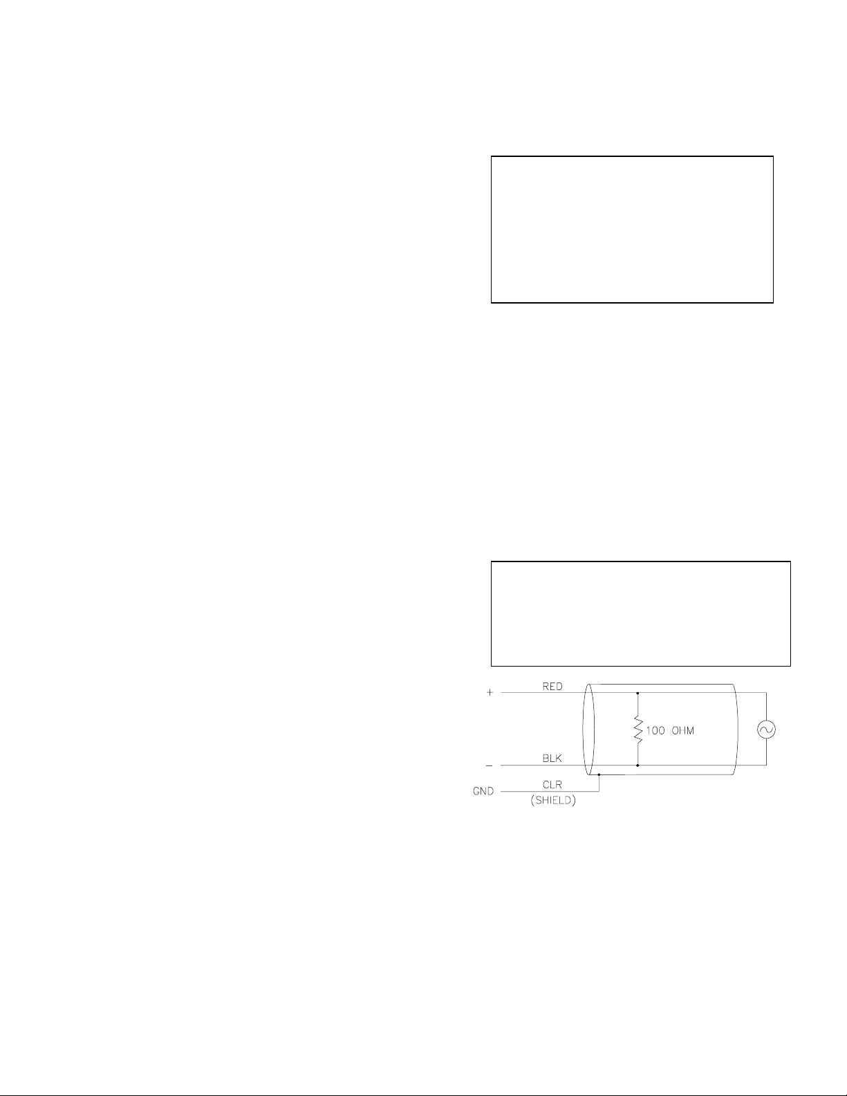
The LI200S (refer to Figure 1) outputs a low
level voltage ranging from 0 to a maximum of
about 12mV depending on sensor calibration
and radiation level. A differential voltage
measurement (Instruction 2) is recommended
because it has better noise rejection than a
single-ended measurement.
If a differential channel is not available, a singleended measurement (Instruction 1) is a
possibility. As a test, wire the LI200S as shown in
Figure 2 and make single-ended and differential
measurements. Compare results to determine
the acceptability of a single ended measurement.
NOTE FOR 21X USERS:
potential differences are created along the 21X
analog terminal strip when the datalogger
power supply is powering external peripherals.
If the peripherals draw about 30mA or greater,
the LI200S must be measured differentially.
Figure 1. LI200S Schematic
INPUT RANGE
An example showing how to determine the
optimum input range for a given sensor
calibration and maximum irradiance follows.
This is an example only. Your values will be
different.
Slight ground
1
Page 4

LI200S PYRANOMETER
EXAMPLE
-Sensor Calibration: Assume the sensor
calibration is 87 microamps kW-1 m-2. The
LI200S outputs amperage which is converted to
voltage by 100 ohm shunt resistor in the cable,
as shown in Figure 1. To convert the calibration
from microamps to millivolts, multiply the
calibration by 0.100. The example calibration
-1 m-2
changes to 8.7 mV kW
.
-Maximum Irradiance: A reasonable estimate
of maximum irradiance at the earth’s surface is
-2
1 kW m
.
-Input Range Selection: An estimate of the
maximum input voltage is obtained by
multiplying the calibration by the maximum
expected irradiance. That product is 8.61mV
for this example. Select the smallest input
range which is greater than the maximum
expected input voltage. In this case the 15mV
range for the 21X and CR7, and the 25mV
range for the CR10 are selected.
Measurement integration time is specified in the
input range parameter code. A more noise free
reading is obtained with the slow or 60 Hz
rejection integration. A fast integration takes
less power and allows for faster throughput.
EXAMPLE
Assume that daily total flux is desired, and the
datalogger scan rate is 1 second. With a
multiplier that converts the readings to units of
-2
and an average irradiance of .5 kW m-2,
kJ m
the maximum low resolution output limit will be
exceeded in less than four hours.
Solution #1 - Record average flux density and
later multiply the result by the number of
seconds in the output interval to arrive at total
flux.
Solution #2 - Record total flux using the high
resolution format. The drawback to high
resolution is that it requires 4 bytes of memory
per data point, consuming twice as much
memory as low resolution.
5. CONNECTIONS
Differential and single-ended connections to the
datalogger are shown in Figures 2 and 3,
respectively.
MULTIPLIER
The multiplier converts the millivolt reading to
engineering units. Commonly used units and
how to calculate the multiplier are shown in
Table 1.
Table 1. Multipliers Required for Flux
Density and Total Fluxes
UNITS
MULTIPLIERS
kJ m-2 (1/C)*t (Total)
kW m-2 (1/C) (Average)
*t*
cal cm-2 (1/C)
cal cm-2 min-1 (1/C)
(0.0239) (Total)
*
(1.434) (Average)
C = (LI-COR calibration)*0.100
t = datalogger program execution
interval in seconds
4. OUTPUT FORMAT CONSIDERATIONS
The largest number that the datalogger can
output is 6999 in low resolution and 99999 in
high resolution (Instruction 78, set resolution). If
the measurement value is totalized, there is
some danger of overranging the output limits,
as shown in the following example.
Figure 2. Differential Measurement
Connection
*AG in Figure 2 refers to Analog Ground in the CR10
which is the same as ground for the 21X and CR7.
On a differential measurement, jumper the low
side of the signal to AG to keep the signal in
common mode range, as shown in Figure 2.
Figure 3. Single-ended Measurement Connection
*AG in Figure 3 refers to Analog Ground in the
CR10, which is the same as ground for the 21X
and CR7.
2
Page 5

LI200S PYRANOMETER
3
Page 6

Page 7

This is a bla nk page.
Page 8

Campbell Scientific Companies
Campbell Scientific, Inc. (CSI)
815 West 1800 North
Logan, Utah 84321
UNITED STATES
www.campbellsci.com
info@campbellsci.com
Campbell Scientific Africa Pty. Ltd. (CSAf)
PO Box 2450
Somerset West 7129
SOUTH AFRICA
www.csafrica.co.za
sales@csafrica.co.za
Campbell Scientific Australia Pty. Ltd. (CSA)
PO Box 444
Thuringo wa Cent ra l
QLD 4812 AUSTRALIA
www.campbellsci.com.au
info@campbellsci.com.au
Campbell Scientific do Brazil Ltda . (CSB)
Rua Luisa Crapsi Orsi, 15 Butantã
CEP: 005543-000 São Paulo SP BRAZIL
www.campbellsci.com.br
suporte@campbellsci.com.br
Campbell Scientific Canada Corp. (CSC)
11564 - 149th Street NW
Edmonton, Alberta T5M 1W7
CANADA
www.campbellsci.ca
dataloggers@campbellsci.ca
Campbell Scientific Ltd. (CSL)
Campbell Park
80 Hathern Road
Shepshed, Loughborough LE12 9GX
UNITED KINGDOM
www.campbellsci.co.uk
sales@campbellsci.co.uk
Campbell Scientific Ltd. (France)
Miniparc du Verger - Bat. H
1, rue de Terre Neuve - Les Ulis
91967 COURTABOEUF CEDEX
FRANCE
www.campbellsci.fr
campbell.scientific@wanadoo.fr
Campbell Scientific Spain, S. L.
Psg. Font 14, local 8
08013 Barcelona
SPAIN
www.campbellsci.es
info@campbellsci.es
Please visit www.campbellsci.com to obtain contact information for your local US or International representative.
 Loading...