

Page 1

L
I
-
C
O
R
Q
U
A
N
T
U
M
Q
1
7
9
9
2
LI190SB Quantum Sensor
Revision: 3/08
Copyright © 1982-2008
Campbell Scientific, Inc.
Page 2

Warranty and Assistance
The LI190SB QUANTUM SENSOR is warranted by CAMPBELL
SCIENTIFIC, INC. to be free from defects in materials and workmanship
under normal use and service for twelve (12) months from date of shipment
unless specified otherwise. Batteries have no warranty. CAMPBELL
SCIENTIFIC, INC.'s obligation under this warranty is limited to repairing or
replacing (at CAMPBELL SCIENTIFIC, INC.'s option) defective products.
The customer shall assume all costs of removing, reinstalling, and shipping
defective products to CAMPBELL SCIENTIFIC, INC. CAMPBELL
SCIENTIFIC, INC. will return such products by surface carrier prepaid. This
warranty shall not apply to any CAMPBELL SCIENTIFIC, INC. products
which have been subjected to modification, misuse, neglect, accidents of
nature, or shipping damage. This warranty is in lieu of all other warranties,
expressed or implied, including warranties of merchantability or fitness for a
particular purpose. CAMPBELL SCIENTIFIC, INC. is not liable for special,
indirect, incidental, or consequential damages.
Products may not be returned without prior authorization. The following
contact information is for US and International customers residing in countries
served by Campbell Scientific, Inc. directly. Affiliate companies handle
repairs for customers within their territories. Please visit
www.campbellsci.com to determine which Campbell Scientific company
serves your country. To obtain a Returned Materials Authorization (RMA),
contact CAMPBELL SCIENTIFIC, INC., phone (435) 753-2342. After an
applications engineer determines the nature of the problem, an RMA number
will be issued. Please write this number clearly on the outside of the shipping
container. CAMPBELL SCIENTIFIC's shipping address is:
CAMPBELL SCIENTIFIC, INC.
RMA#_____
815 West 1800 North
Logan, Utah 84321-1784
CAMPBELL SCIENTIFIC, INC. does not accept collect calls.
Page 3

LI190SB Table of Contents
PDF viewers note: These page numbers refer to the printed version of this document. Use
the Adobe Acrobat® bookmarks tab for links to specific sections.
1. General Description.....................................................1
2. Specifications ..............................................................2
3. Installation....................................................................3
4. Wiring............................................................................4
5. Programming ...............................................................5
5.1 Input Range...............................................................................................7
5.2 Example Programs....................................................................................8
5.2.1 CR1000 Example Program.............................................................8
5.2.2 CR10X Example Program ..............................................................9
5.3 Output Format Considerations................................................................10
6. Maintenance and Calibration....................................11
7. Troubleshooting ........................................................11
8. Acknowledgements...................................................11
Figures
1-1. LI190SB Spectral Response....................................................................1
2-1. LI190SB Quantum Sensor.......................................................................2
3-1. CM225 Pyranometer Mounting Stand and CM202 Crossarm................ 3
3-2. 015 Pyranometer Mounting Arm.............................................................4
3-3. 025 Crossarm Stand and 019ALU Crossarm..........................................4
4-1. LI190SB Schematic.................................................................................5
5-1. Differential Measurement Connection.................................................... 6
5-2. Single-ended Measurement Connection..................................................6
Tables
4-1. Connections to Campbell Scientific Dataloggers....................................5
5-1. Multiplier Required for Flux Density and Total Fluxes..........................7
5-2. Wiring for Example Programs ................................................................8
i
Page 4

Page 5
LI190SB Quantum Sensor
1. General Description
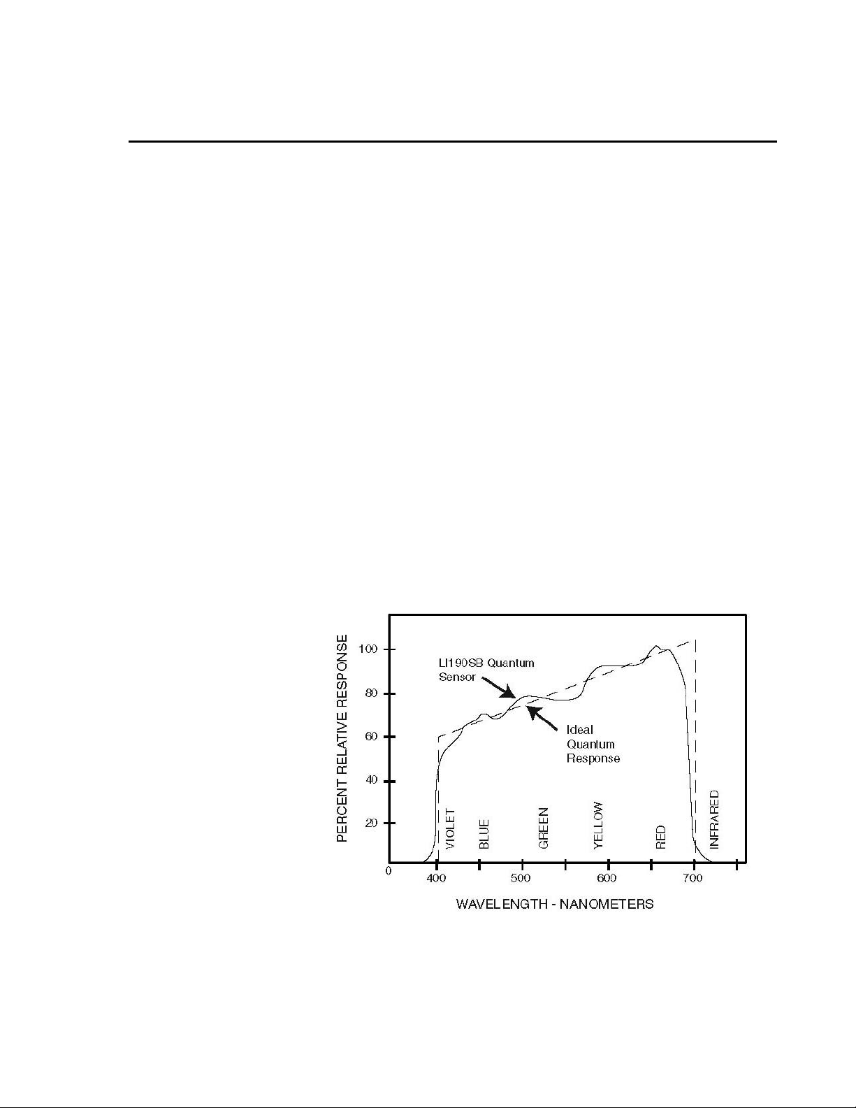
The LI190SB quantum sensor measures photosynthetically active radiation
(PAR) in the 400 to 700 nm waveband. The unit of measurement is µmoles
per second per square meter (µmol s
The quantum sensor is designed to measure PAR received on a plane surface.
The indicated sensor response (Figure 1-1) is selected because it approximates
the photosynthetic response of plants for which data are available. A silicon
photodiode with an enhanced response in the visible wavelengths is used as the
sensor. A visible bandpass interference filter in combination with colored
glass filters is mounted in a cosine corrected head.
Measuring PAR within plant canopies, greenhouses, controlled environment
chambers, confined laboratory conditions, or at remote environmental
monitoring sites are all typical applications for this sensor.
During the night the LI190SB may output a slightly negative value, caused by
RF noise. Negative values may be set to zero in the datalogger program.
A Calibration Certificate is shipped with each sensor that includes a serial
number and calibration constant. The calibration constant is unique for each
sensor, and is used to compute the multiplier for the measurement instruction
in the datalogger program.
-1m-2
).
FIGURE 1-1. LI190SB Spectral Response
1
Page 6
LI190SB Quantum Sensor
L
I
-
C
O
R
Q
U
A
N
T
U
M
Q
1
7
9
9
2
2. Specifications
Stability: <±2% change over a 1 year period
Response Time: 10 μs
Temperature
Dependence: 0.15% per °C maximum
Cosine Correction: Cosine corrected up to 80° angle of incidence
Operating
Temperature: -40 to 65°C
Relative Humidity: 0 to 100%
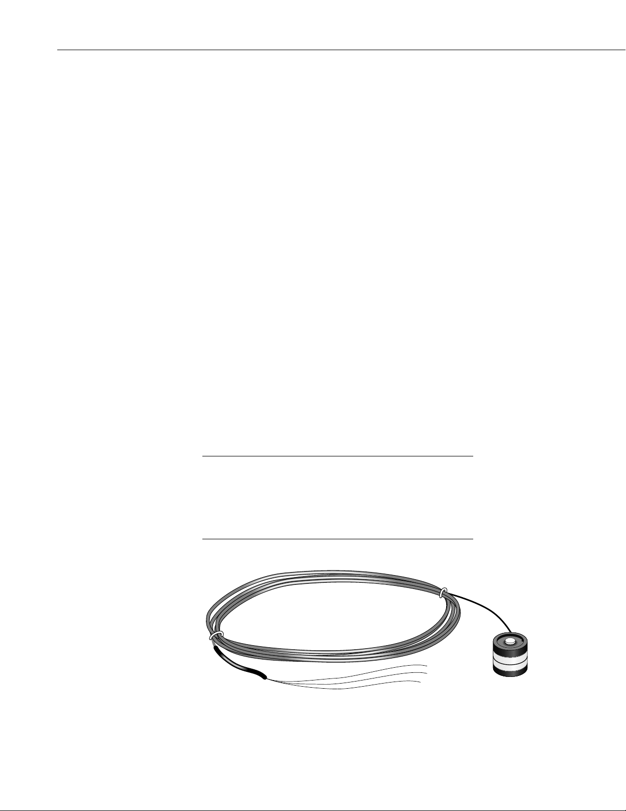
Detector: High stability silicon photovoltaic detector (blue
Sensor Housing: Weatherproof anodized aluminum case with acrylic
Size: 0.94” dia x 1.00” H (2.38 x 2.54 cm);
Weight: 1 oz. (28 g)
enhanced)
diffuser and stainless steel hardware
NOTE
Calibration: ±5% traceable to the U.S. National Institute of
Standards Technology (NIST)
Sensitivity: Typically 5 μA per 1000 μmoles s
-1m-2
Linearity: Maximum deviation of 1% up to 10,000 μmoles s
Shunt Resistor: 604 ohms
Light Spectrum
Waveband: 400 to 700 nm
®
The black outer jacket of the cable is Santoprene
rubber. This
compound was chosen for its resistance to temperature extremes,
moisture, and UV degradation. However, this jacket will
support combustion in air. It is rated as slow burning when
tested according to U.L. 94 H.B. and will pass FMVSS302.
Local fire codes may preclude its use inside buildings.
-1m-2
FIGURE 2-1. LI190SB Quantum Sensor
2
Page 7

3. Installation
LI190SB Quantum Sensor
The LI190SB should be mounted such that it is never shaded by the
tripod/tower or other instrumentation. The sensor should be mounted with the
cable pointed towards the nearest magnetic pole, e.g. in the Northern
Hemisphere point the cable towards the North Pole.
Mounting height is not critical for the accuracy of the measurement. However,
pyranometers mounted at heights of 3 m or less are easier to level and clean.
To ensure accurate measurements, the LI190SB should be mounted using
LI2003S base/leveling fixture. This base incorporates a bubble level and three
adjustment screws. The LI190SB and base/leveling fixture are attached to a
tripod or tower using one of three mounting configurations (see Figure 3-1
through 3-3).
Tools required for installation on a tripod or tower:
Small and medium Phillips screwdrivers
5/32” Allen wrench for NU-RAIL (Figure 3-3)
1/2” open end wrench for 015ARM or CM225 (Figures 3-1, 3-2)
Tape measure
UV-resistant wire ties
Side-cut pliers
Compass
Step ladder
LI190SB Pyranometer
CM200 Series Crossarm
FIGURE 3-1. CM225 Pyranometer Mounting Stand
LI2003S
CM225 Stand
and CM202 Crossarm
3
Page 8

LI190SB Quantum Sensor
NOTE
Remove the red cap after installing the sensor. Save this cap for
shipping or storing the sensor.
FIGURE 3-2. 015 Pyranometer Mounting Arm
4. Wiring
4
FIGURE 3-3. 025 Crossarm Stand and 019ALU Crossarm
A schematic diagram of the LI190SB is shown in Figure 4-1.
Connections to Campbell Scientific dataloggers are given in Table 4-1. When
Short Cut software is used to create the datalogger program, the sensor should
be wired to the channels shown in the wiring diagram created by Short Cut.
Page 9

LI190SB Quantum Sensor
TABLE 4-1. Connections to Campbell Scientific Dataloggers
Color
Description
CR9000(X)
CR5000
CR3000
CR1000
CR800
CR850
Red Signal Differential
High
Black Signal
Reference
Clear Shield
Differential
Low
CR510
CR500
CR10(X)
Differential
High
Differential
Low
G
21X
CR7
CR23X
Differential
High
Differential
Low
NOTE
5. Programming
*Jumper to AG or
with user supplied wire.
FIGURE 4-1. LI190SB Schematic
If a 21X is used to measure the LI190SB and powers a 12 VDC
sensor, the current drawn by the 12 VDC sensor may cause a
difference in ground potential between the 21X ground terminals
and the reference ground point in the datalogger. This ground
potential results in an offset on single ended measurements. This
offset can be as large as ± 60 mV. Thus, single ended
measurements should be avoided. The offset does not, however,
affect differential measurements.
This section is for users who write their own datalogger programs. A
datalogger program to measure the LI190SB can be created using the Short
Cut software. You do not need to read the following section to use Short Cut.
5
Page 10

LI190SB Quantum Sensor
Output from the LI190SB is a voltage raning from 0 to a maximum of 10 mV
depending on sensor calibration and radiation level, which is measured by the
datalogger using a Differential analog input channel. To measure the output,
Edlog dataloggers (e.g. CR10X, CR23X) are programmed with Instruction 2
Volt(DIFF), CRBasic dataloggers (e.g. CR1000, CR3000) are programmed
with the VoltDiff Instruction.
Nearby AC power lines, electric pumps, or motors can be a source of electrical
noise. If the sensor or datalogger is located in an electrically noisy
environment, the measurement should be made with the 60 or 50 Hz rejection
integration option as shown in the example programs.
-1m-2
Solar radiation can be reported as an average flux density (µmole s
daily total flux density (mmoles m
-2
). The appropriate multipliers are listed in
) or
Table 5-1. Programming examples are given for both average and daily total
photosynthetically active radiation (PAR). Negative values are set to zero
before being processed.
If a differential channel is not available, a single-ended measurement
(Instruction 1) is a possibility. As a test, wire the LI190SB as shown in Figure
5-1 and make single-ended and differential measurements. Compare the
results to determine the acceptability of a single ended measurement.
6
FIGURE 5-1. Differential Measurement Connection
FIGURE 5-2. Single-ended Measurement Connection
Page 11

5.1 Input Range
LI190SB Quantum Sensor
An example showing how to determine the optimum input range for a given
sensor calibration and maximum photosynthetically active radiation (PAR) is
given below. This is an example only. Your values will be different.
-Sensor Calibration: Assume the sensor calibration is 8 µA/1000 µmoles
-1m-2
(1000 µmoles = 1 mmole). The LI190SB outputs amperage which is
s
converted to voltage by a 604 ohm shunt resistor in the cable. To convert the
calibration from µA to millivolts, multiply the calibration by 0.604. The
example calibration changes to 4.83 mV/mmole s
-Maximum PAR: A reasonable estimate of maximum PAR is 2 mmoles
-1m-2
.
s
-1m-2
.
-Input Range Selection: An estimate of the maximum input voltage is
obtained by multiplying the calibration by the maximum expected PAR. That
product is 9.66 mV for this example. Select the smallest input range which is
greater than the maximum expected input voltage. In this case, the 15 mV
range for the 21X and CR7, and the 25 mV range for the CR10(X) and CR500
are selected.
Measurement integration time is specified in the input range parameter code.
A more noise free reading is obtained with the slow or 60 Hz rejection
integration. A fast integration takes less power and allows for faster
throughput.
MULTIPLIER
The multiplier converts the millivolt reading to engineering units. Commonly
used units and how to calculate the multiplier are shown in Tab le 5-1.
TABLE 5-1. Multiplier Required for
Flux Density and Total Fluxes
UNITS MULTIPLIER
µmole s-1 m-2 1000/C (flux density)
mmoles m-2 (1/C)*t (total fluxes)
C = (LI-COR calibration)*0.604
t = datalogger program execution interval in
seconds
Unit Conversions
microEinstien/µmole
17
(6.02 x 10
photons s-1 m-2)/(µmoles s-1 m-2)
7
Page 12

LI190SB Quantum Sensor
5.2 Example Programs
The following programs measure the LI190SB every 10 seconds, and convert
the mV output to µmoles s
hourly average flux (µmoles s
-2
). Wiring for the examples is given in Table 5-2. Multipliers in the
m
example programs are based upon a sensor with a calibration constant of 6.45
µA/1000 µmoles s
-1m-2
-1m-2
and mmoles m-2. Both programs output an
-1m-2
) and a daily total flux density (mmoles
.
TABLE 5-2. Wiring for Example Programs
Color Description CR1000 CR10X
Red Signal 1H 1H
*Black Signal Reference 1L 1L
Clear Shield
G
*Jumper to AG or with user supplied wire.
5.2.1 CR1000 Example Program
'CR1000
'Declare Variables and Units
Public PAR_Den
Public PAR_Tot
Units PAR_Den=µmol/s/m²
Units PAR_Tot=mmol/m²
'Define Data Tables
DataTable(Table1,True,-1)
DataInterval(0,60,Min,10)
Average(1,PAR_Den,FP2,False)
EndTable
DataTable(Table2,True,-1)
DataInterval(0,1440,Min,10)
Totalize(1,PAR_Tot,IEEE4,False)
EndTable
'Main Program
BeginProg
Scan(10,Sec,1,0)
'LI190SB Quantum Sensor measurements PAR_Tot and PAR_Den:
VoltDiff(PAR_Den,1,mV25,1,True,0,_60Hz,1,0) 'Use 20 mV range for CR3000, CR5000
'Set negative values to zero
If PAR_Den<0 Then PAR_Den=0
PAR_Tot=PAR_Den*2.56686 'Multipliers will differ for each sensor and scan rate
PAR_Den=PAR_Den*256.686
'Call Data Tables and Store Data
CallTable(Table1)
CallTable(Table2)
NextScan
EndProg
8
Page 13

LI190SB Quantum Sensor
5.2.2 CR10X Example Program
;{CR10X}
*Table 1 Program
01: 10.0000 Execution Interval (seconds)
;Measure LI190SB
1: Volt (Diff) (P2)
1: 1 Reps
2: 23 25 mV 60 Hz Rejection Range ;15 mV for 21X, CR7; 10 mV for CR23X
3: 1 DIFF Channel
4: 3 Loc [ PAR_Den ]
5: 1 Multiplier
6: 0 Offset
;Set negative values to zero
2: If (X<=>F) (P89)
1: 3 X Loc [ PAR_Den ]
2: 4 <
3: 0 F
4: 30 Then Do
3: Z=F x 10^n (P30)
1: 0 F
2: 0 n, Exponent of 10
3: 3 Z Loc [ PAR_Den ]
4: End (P95)
;Convert mV to mmoles m-2 for 10 second scan
5: Z=X*F (P37)
1: 3 X Loc [ PAR_Den ]
2: 2.56686 F ;Will differ for each sensor and scan rate
3: 4 Z Loc [ PAR_Tot ]
;Convert mV to µmoles s-1m-2
6: Z=X*F (P37)
1: 3 X Loc [ PAR_Den ]
2: 256.686 F ;Will differ for each sensor
3: 3 Z Loc [ PAR_Den ]
7: If time is (P92)
1: 0 Minutes (Seconds --) into a
2: 60 Interval (same units as above)
3: 10 Set Output Flag High (Flag 0)
8: Set Active Storage Area (P80)
1: 1 Final Storage Area 1
2: 101 Array ID
9: Real Time (P77)
1: 1220 Year,Day,Hour/Minute (midnight = 2400)
9
Page 14

LI190SB Quantum Sensor
10: Average (P71)
1: 1 Reps
2: 3 Loc [ PAR_Den ]
11: If time is (P92)
1: 0 Minutes (Seconds --) into a
2: 1440 Interval (same units as above)
3: 10 Set Output Flag High (Flag 0)
12: Set Active Storage Area (P80)
1: 1 Final Storage Area 1
2: 102 Array ID
13: Real Time (P77)
1: 1220 Year,Day,Hour/Minute (midnight = 2400)
14: Resolution (P78)
1: 1 High Resolution
15: Totalize (P72)
1: 1 Reps
2: 4 Loc [ PAR_Tot ]
16: Resolution (P78)
1: 0 Low Resolution
5.3 Output Format Considerations
If solar radiation is totalized in units of mmoles m-2, there is a possibility of
overranging the output limits. With the Edlog dataloggers (e.g. CR10X,
CR23X, CR510) the largest number that the datalogger can output to final
storage is 6999 in low resolution (default), and 99999 in high resolution.
The largest number that the datalogger can output is 6999 in low resolution
and 99999 in high resolution (Instruction 78, set resolution). If the
measurement value is totalized, there is some danger of overranging the output
limits, as shown in the following example.
EXAMPLE
Assume that daily total flux is desired, and the datalogger scan rate is 1 second.
With a multiplier that converts the readings to units of mmoles m
average PAR of 1 µmole s
be exceeded in less than 2 hours (6999 seconds).
Solution #1 - Record average flux density and later multiply the result by the
number of seconds in the output interval to arrive at total flux.
Solution #2 - Record total flux using the high resolution format. Another
alternative is to record total flux using the high resolution format. Instruction
78 is used to switch to the high resolution in the Edlog dataloggers. Use the
IEEE4 or Long data formats in the CR1000, CR5000, and CR9000
dataloggers. The disadvantage of the high resolution formats is that it takes
more memory per data point.
-1 m-2
-2
and an
, the maximum low resolution output limit will
10
Page 15

6. Maintenance and Calibration
DO NOT use alcohol, organic solvents, abrasives, or strong detergents to clean
the diffuser element.
The acrylic materials used in LI-COR light sensors can be crazed by exposure
to alcohol or organic solvents, which will adversely affect the cosine response
of the sensor.
Clean the sensor only with water and/or a mild detergent such as dishwashing
soap. Vinegar can also be used to remove hard water deposits from the
diffuser element, if necessary.
Keep the sensors clean and treat them as a scientific instrument in order to
maintain the accuracy of the calibration. The vertical edge of the diffuser must
be kept clean in order to maintain appropriate cosine correction.
The LI190SB should re recalibrated every two years. Obtain an RMA number
before returning the sensor to Campbell Scientific, Inc. for recalibration.
7. Troubleshooting
LI190SB Quantum Sensor
Symptom: -9999 or radiation values around 0
1. Check that the sensor is wired to the Differential channel specified by the
measurement instruction.
2. Verify that the Range code is correct for the datalogger type.
3. Disconnect the sensor leads from the datalogger and use a DVM to check
the voltage between the red (+) and the black (-) wires. The voltage
should be 0 – 10 mV for 0 to 1000 Wm
problem with the photodiode, cable, or the variable shunt resistor.
Symptom: Incorrect solar radiation
1. Make sure the top surface of the sensor head is clean, and that the sensor
is properly leveled.
2. Verify that the Range code, multiplier and offset parameters are correct
for the desired engineering units and datalogger type.
8. Acknowledgements
Campbell Scientific, Inc. gratefully acknowledges the contribution of LI-COR
to concepts, text, and images used in this manual.
-2
radiation. No voltage indicates a
11
Page 16

LI190SB Quantum Sensor
12
Page 17

This is a blank page.
Page 18

Campbell Scientific Companies
Campbell Scientific, Inc. (CSI)
815 West 1800 North
Logan, Utah 84321
UNITED STATES
www.campbellsci.com
info@campbellsci.com
Campbell Scientific Africa Pty. Ltd. (CSAf)
PO Box 2450
Somerset West 7129
SOUTH AFRICA
www.csafrica.co.za
cleroux@csafrica.co.za
Campbell Scientific Australi
PO Box 444
Thuringowa Central
QLD 4812 AUSTRALIA
www.campbellsci.com.au
info@campbellsci.com.au
Campbell Scientific do Brazil Ltda. (CSB)
Rua Luisa Crapsi Orsi, 15 Butantã
CEP: 005543-000 São Paulo SP BRAZIL
www.campbellsci.com.br
suporte@campbellsci.com.br
Campbell Scientific Canada Corp. (CSC)
11564 - 149th Street NW
Edmonton, Alberta T5M 1W7
CANADA
www.campbellsci.ca
dataloggers@campbellsci.ca
Campbell Scientific Ltd. (CSL)
Campbell Park
80 Hathern Road
Shepshed, Loughborough LE12 9GX
UNITED KINGDOM
www.campbellsci.co.uk
sales@campbellsci.co.uk
Campbell Scientific Ltd. (France)
Miniparc du Verger - Bat. H
1, rue de Terre Neuve - Les Ulis
91967 COURTABOEUF CEDEX
FRANCE
www.campbellsci.fr
info@campbellsci.fr
Campbell Scientific Spain, S. L.
Psg. Font 14, local 8
08013 Barcelona
SPAIN
www.campbellsci.es
info@campbellsci.es
Please visit www.campbellsci.com to obtain contact information for your local US or International representative.
a Pty. Ltd. (CSA)
 Loading...