

Page 1
Revision: 03/2021
Copyright © 2020 – 2021
Campbell Scientific, Inc.
Page 2

Table of contents
1. Introduction 1
2. Precautionary statements 1
3. Initial inspection 1
4. Overview 2
5. Specifications 4
5.1 Pressure transducer 4
5.2 Air flow 4
5.3 Power 5
5.4 Communications 5
5.5 Enclosure 6
5.6 Environmental 6
6. Installation 6
6.1 Verify operation 6
6.2 Wiring 7
6.3 Power considerations 8
6.4 Default settings 9
6.5 Setup using keypad/display 11
6.6 Campbell Scientific data logger programming 13
6.6.1 SDI-12 programming 13
6.6.2 RS-485 programming 13
6.7 Field installation 14
6.7.1 Site selection 14
6.7.2 Enclosure mounting 14
6.7.3 Desiccator installation 15
6.7.4 Orifice line and conduit installation 17
7. Operation 19
7.1 Principles of operation 19
7.2 Keypad/display menu 20
7.2.1 Stage setup 21
7.2.2 Bubbler setup 21
Table of Contents - i
Page 3

7.2.3 System setup 22
7.2.4 Communication setup 23
7.2.5 Diagnostic/Test 23
7.2.6 System information 27
7.3 SDI-12 measurement and extended commands 27
7.4 Modbus register map 30
7.5 Secured orifice line 35
7.6 Long orifice lines 37
7.7 Orifice-line outlet orientation 37
7.8 Orifice-line outlet types 38
8. Maintenance and troubleshooting 39
8.1 Replacing desiccant 39
8.2 Lithium battery replacement 40
8.3 Plugged orifice outlet 41
8.4 Cold weather 42
8.5 Preventing or fixing orifice-line leaks 42
8.6 Updating operating system 42
8.7 Troubleshooting 43
Appendix A. Example program 46
Appendix B. SDI-12 sensor support 48
B.1 SDI-12 command basics 48
B.1.1 Acknowledge active command (a!) 49
B.1.2 Send identification command (al!) 49
B.1.3 Start verification command (aV!) 50
B.1.4 Address query command (?!) 50
B.1.5 Change address command (aAb!) 50
B.1.6 Start measurement commands (aM!) 51
B.1.7 Start concurrent measurement commands (aC!) 51
B.1.8 Start measurement commands with cyclic redundancy check (aMC! and aCC!) 53
B.1.9 Stopping a measurement command 53
B.1.10 Send data command (aD0! … aD9!) 53
B.1.11 Extended commands 54
B.1.12 SDI-12 version 1.4 identify measurement commands and responses 54
B.2 SDI-12 transparent mode 55
B.2.1 Changing an SDI-12 address 56
Table of Contents - ii
Page 4

B.3 References 58
Appendix C. Field calibration check 59
Table of Contents - iii
Page 5

1. Introduction
The LevelVUE B10 is a continuous-air-flow bubbler that measures ground water, surface water, or
any liquid level. It consists of an integrated circuit board, pressure sensors to measure and control
tank and line pressures, a 12VDC industrial compressor, a 0.8 liter air tank, and an integrated
keypad/display. Three pressure ranges are available: 15psi (34.6ft, 10.5m), 30psi (69.2ft,
21.0m), or 50psi (115ft, 35.0m). The bubbler communicates with a data logger or RTU using
either SDI-12 or Modbus protocols. Although this document only includes example programs for
Campbell Scientific CRBasic data loggers, any data logging device capable of SDI-12 or Modbus
communications can be used to retrieve the LevelVUE B10 measurements.
2. Precautionary statements
l READ AND UNDERSTAND the Safety section at the back of this manual.
l Not using a desiccator will void your warranty. Campbell Scientific offers a desiccator kit,
which is recommended for use with the LevelVUE B10.
l The sensor can survive temporary operation for 1.5 times the maximum rated pressure
(Table 5-1 (p. 4). However, measurements made beyond the rated pressure range will be
inaccurate.
l Do not use quick connect fittings as these tend to leak.
l Mount the LevelVUE B10 in a location where it will not get jarred or shift during operation.
3. Initial inspection
l Upon receipt of the LevelVUE B10, inspect the packaging for shipping damage, and, if
found, report the damage to the carrier in accordance with policy.
l Carefully open the package to avoid damaging or cutting the orifice-line tubing (if
ordered). A thorough inspection of the tubing is prudent.
LevelVUE™B10 Water-Level Bubbler 1
Page 6

l Compare the pressure range printed on the bottom of the enclosure with the pressure
range listed in the shipping document to ensure that the correct pressure range was
received.
l Verify that the orifice line Swagelok® fitting and air intake line barbed fitting were shipped
with the LevelVUE B10. They are shipped in a small bag inside the enclosure. Do the
following to locate these items:
o
Open the enclosure lid
o
Press on the black magnet
o
Lift the keypad panel
l
NOTE:
The orifice line Swagelok® fitting may already be installed on the LevelVUE B10.
l Verify that all bubbler accessories were sent. The following accessories (ordered separately)
are often shipped with the LevelVUE B10:
o
Orifice line
o
Desiccator kit
o
Desiccant
4. Overview
The LevelVUE B10 bubbler incorporates all the components of a self-contained pressurized air
supply system. It has an air compressor, air tank, and other components of older conoflow
systems. However, instead of pressurized air tanks and manual valves used in conoflow systems,
the LevelVUE B10 meters the airflow to create a constant flow in the line regardless of the water
depth above the orifice. Precision sensors monitor the tank and line pressures to consistently
maintain the same airflow. The precision sensor monitoring the pressure on the orifice line
precisely detects the pressure required to push air through the line. This pressure value is directly
related to water depth. A simple conversion is applied to the pressure value to generate water
depth in feet, meters, or other units. Proprietary electronics control the pump and calculate the
measurements. The LevelVUE B10 has a digital SDI-12 or RS-485 output that allows any data
logger that supports SDI-12 or Modbus protocols to retrieve the LevelVUE B10 measurements.
FIGURE 4-1 (p. 3) shows a LevelVUE B10-based system that uses a Campbell Scientific data logger
and SDI-12 protocol.
LevelVUE™B10 Water-Level Bubbler 2
Page 7
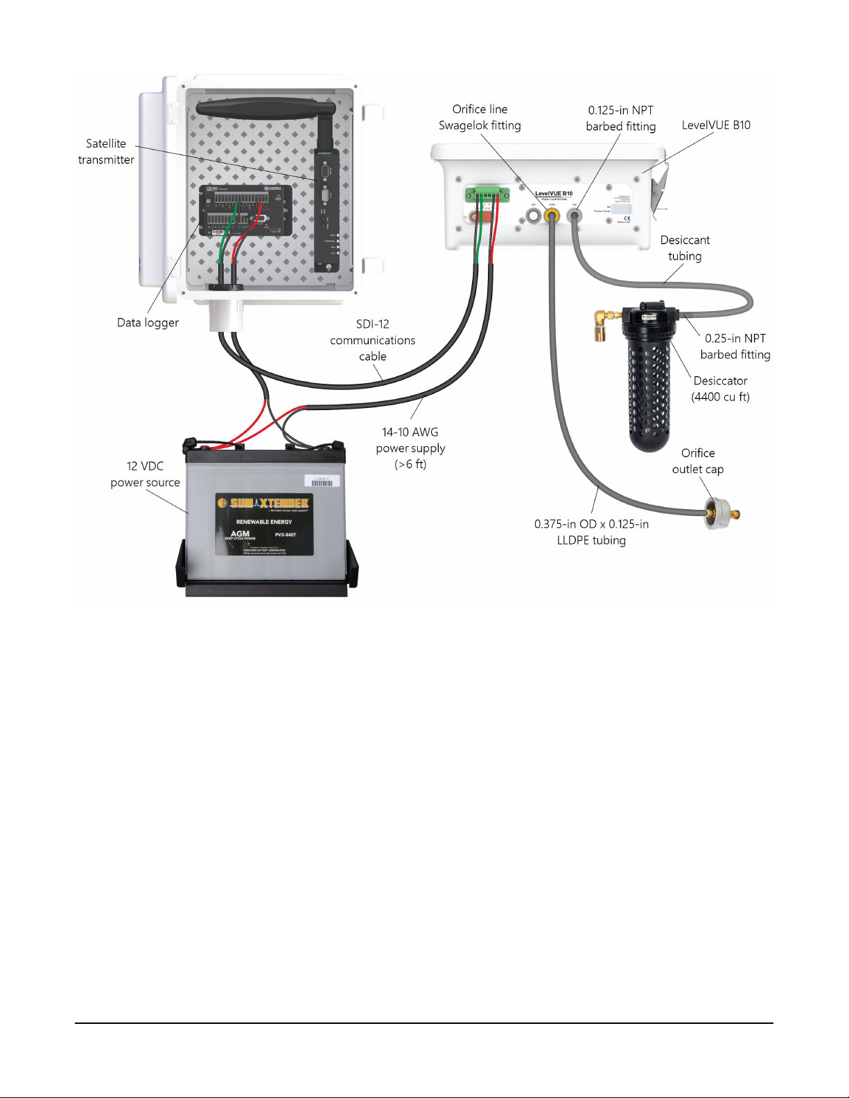
FIGURE 4-1. Components in a LevelVUE B10-based system
The LevelVUE B10 environmental enclosure can be mounted next to rivers, in stilling wells, or on
or near bridges. Only the orifice line contacts the water, which allows the bubbler to work in
areas that would damage submersed sensors due to corrosion, contamination, flood-related
debris, lightning, or vandalism. It also can be used in stream beds that periodically dry up or in
sub-zero temperatures if the water is still flowing. Unlike radar gages, bubbler measurements are
not affected by wind.
Features:
l Proprietary high-pressure/high-volume purge operation to prevent sediment buildup
l High-volume industrial air compressor
l Low power consumption
l –40 to 60 °C operation
LevelVUE™B10 Water-Level Bubbler 3
Page 8
l Three pressure ranges: 15 psi, 30 psi, and 50 psi
l Built-in keypad/display for full setup, measurement, and maintenance operations
l Proprietary air flow/bubble generation for years of trouble-free operation
l Large volume desiccator to minimize maintenance frequency
l Incorporated SDI-12 version 1.4 metadata commands for identification of data
l Compatible with SDI-12 and Modbus controllers including Campbell Scientific CR300
series, CR6 series, CR800 series, CR1000X series, CR3000, and GRANITE-series data loggers
l High water mark detection (crest stage) between normal SDI-12 measurement requests
5. Specifications
Compliance documents:
View at www.campbellsci.com/levelvueb10
5.1 Pressure transducer
Table 5-1: Pressure range, depth, and resolution
Pressure range
0 to 15 psi 0 to 10.54 m (34.6 ft) ±2.1 mm (0.007 ft)
0 to 30 psi 0 to 21 m (69.20 ft) ±4.26 mm (0.014 ft)
0 to 50 psi 0 to 35.16 m (115.35 ft) ±7.11 mm (0.023 ft)
1
Level calculations assume 1 psi = 0.7031 m (2.3067 ft) of water.
Accuracy:
Sensor overpressure rating:
≤ 0.02% of full scale output (FSO)
over temperature range
1.5 times the pressure range
Water depth range
1
Resolution
5.2 Air flow
Description:
Bubble rate: Programmable 30 to 120 bubbles per minutes;
Microprocessor controlled constant air flow
over full pressure range and temperature.
based on 6.35 mm (0.25 inch) inner-diameter outlet.
60 bubbles per minute default
LevelVUE™B10 Water-Level Bubbler 4
Page 9

Purge operation
Manual:
SDI-12:
Modbus:
Automatic-timed purge:
Purge pressure:
Purge sustain time:
Pressure inlet port:
Orifice-line outlet port:
Requested from keypad/display
Command for purge under program control
Command for purge under program control
Once a day to once a month with 1 day resolution
30 to 90 psi, programmable
0 to 30 s, programmable
1/8-inch female NPT
1/8-inch female NPT
5.3 Power
Input voltage range: 11.5 to 16.5 VDC
Current
Standby: 5 mA
Compressor active: 7 A typical, 10 A maximum
Start-up surge current: 18 A maximum
5.4 Communications
SDI-12
Response time:
Default address:
RS-485
Protocol:
Default address:
Default configuration:
Data type:
Built-in keypad/display: Graphical 8-line-by-20-character display.
SDI-12 V 1.4 compliant
10 s forM!SDI-12 command with default averaging time of
5seconds
0
Modbus
1
8-bit, even parity, 1 stop bit, 19200 bps baud rate
32-bit float, no reversal of the byte order (ABCD)
Menu fully supports system setup.
LevelVUE™B10 Water-Level Bubbler 5
Page 10

5.5 Enclosure
Material:
Width:
Height:
Depth:
Weight:
Fiberglass
28.9 cm (11.4 in)
34 cm (13.4 in)
13 cm (5.2 inch)
7.5 kg (16.5 lb)
5.6 Environmental
Operating temperature:
Storage temperature:
Relative humidity:
–40 to 60 °C
–40 to 80 °C
0 to 95%, non-condensing
6. Installation
6.1 Verify operation 6
6.2 Wiring 7
6.3 Power considerations 8
6.4 Default settings 9
6.5 Setup using keypad/display 11
6.6 Campbell Scientific data logger programming 13
6.7 Field installation 14
6.1 Verify operation
Before installing the LevelVUE B10, verify its operation using the following procedure:
1. Remove the plug from the orifice line Outlet fitting on the LevelVUE B10. Save the plug for
use later.
2. Connect the LevelVUE B10 to the power supply (Wiring (p. 7)). After connecting the
bubbler to the power supply, the bubbler will take an initial atmospheric measurement and
LevelVUE™B10 Water-Level Bubbler 6
Page 11
calibrate itself. The compressor also will turn on to initially charge the tank and start the
flow of air out of the system. If the compressor does not turn on, check the power supply.
The LevelVUE B10 must be connected directly to the battery.
3. Connect a short piece of orifice line tubing to the Outlet fitting and place the end of the
tubing in a bucket or tube of water, and bubbles should appear in 15 to 20 seconds.
4. Press the soft key button directly under Measure on the display to initiate a measurement
sequence. Once the measurement is complete ensure that the reading is reasonable based
on the depth of the orifice line and an offset of 0.00.
5. Press the soft key button directly under Purge on the display to initiate a line purge. The
compressor will charge the tank to 60 psi and release the air out the orifice line. This may
take a few seconds.
6.2 Wiring
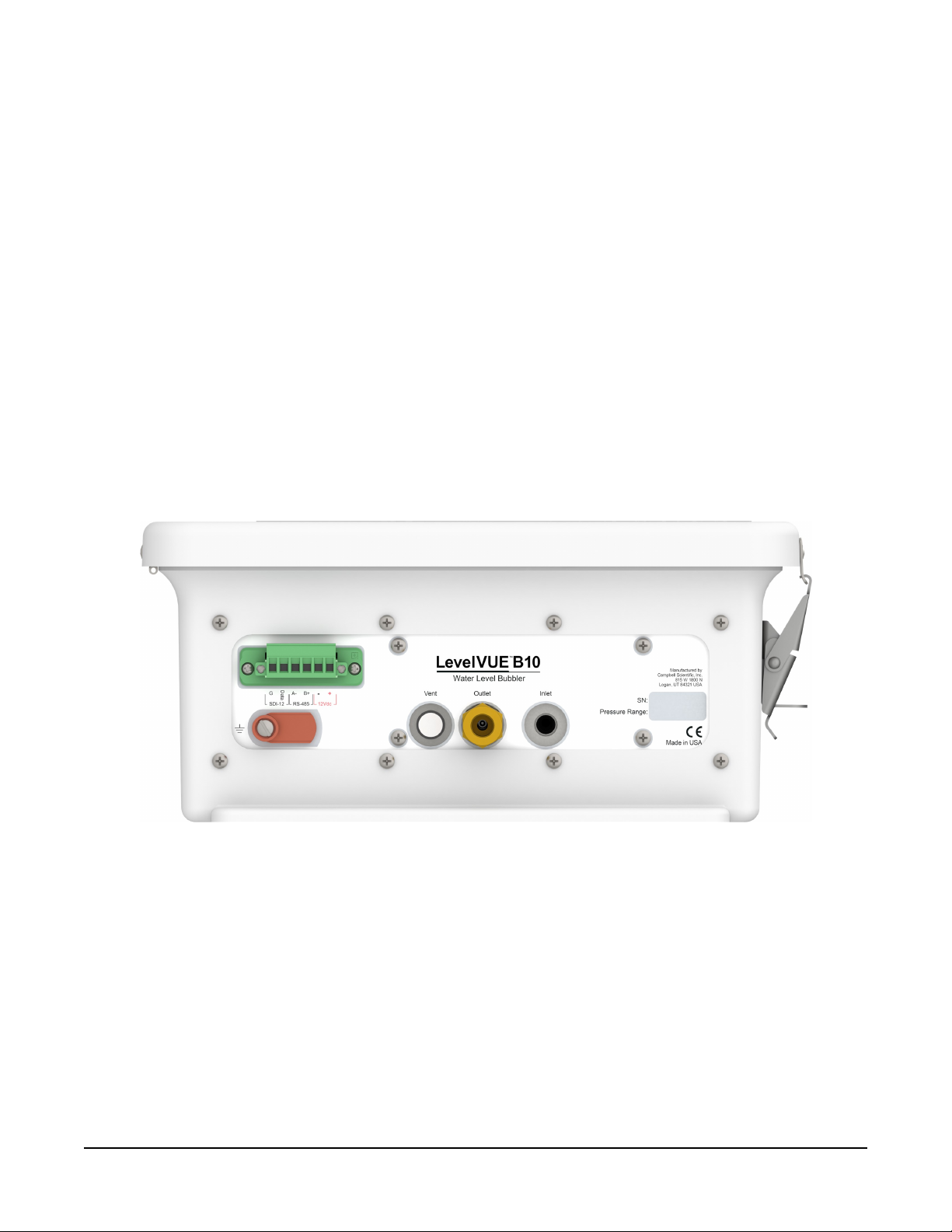
Terminals and connectors are on the bottom of the LevelVUE B10 enclosure (FIGURE 6-1 (p. 7)).
FIGURE 6-1. LevelVUE B10 connector panel
Table 6-1 (p. 8) provides wiring to a data logger when using SDI-12 and Table 6-2 (p. 8) provides
wiring to a data logger when using Modbus. The air compressor and electronics connect directly
to the battery using a 16 to 20AWG wire. Keep wire lengths less than 3m (6ft).
The SDI-12 output can be directly read by many devices including all Campbell Scientific data
loggers. RS-485 output can be directly read by a CR6-series, CR1000X-series, or Modbus RTU
RS-485 network. Other Campbell Scientific data loggers can use an MD485 multidrop interface
to read the RS-485 output. Refer to the MD485 manual for information about using the MD485.
LevelVUE™B10 Water-Level Bubbler 7
Page 12
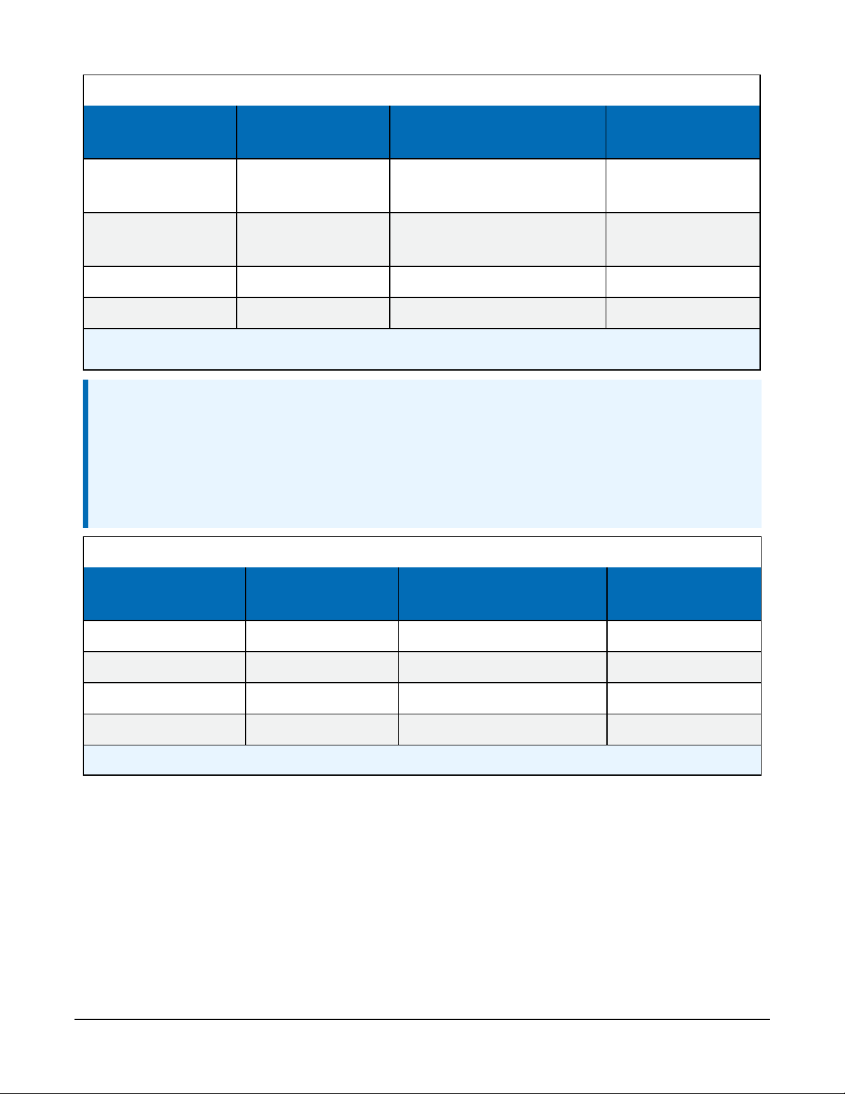
Table 6-1: LevelVUE B10 terminal, function, and connections for SDI-12 measurements
LevelVUE B10
Function Data logger or RTU terminal Power supply
terminal
SDI-12 Data, C, SDI-12,
SDI-12 Data SDI-12 signal
or U configured for SDI-12
1
⏚ or G (digital ground
SDI-12 G Ground
connection)
12Vdc + Power 12V
12Vdc – Power ground G, GND
1
U and C terminals are automatically configured by the measurement instruction for Campbell Scientific CR6 data
logger.
NOTE:
For Campbell Scientific CR6 and CR1000X data loggers making SDI-12 measurements,
conflicts may occur when a companion terminal is used for a triggering instruction such as
TimerInput(), PulseCount(), or WaitDigTrig(). For example, if the LevelVUE
B10 is connected to C3 on a CR1000X, C4 cannot be used in the TimerInput(),
PulseCount(), or WaitDigTrig() instructions.
Table 6-2: LevelVUE B10 terminal, function, and connections for Modbus measurements
LevelVUE B10
Function
terminal
Data logger or RTU
terminal
1
Power supply
RS-485 A– RS-485A A–, C odd
RS-485 B+ RS-485B B+, C even
12Vdc + Power 12V
12Vdc – Power ground G, GND
1
Assumes the sensor directly connects to the data logger.
6.3 Power considerations
The current load of the internal compressor requires the LevelVUE B10 to be connected directly to
the 12VDC battery. The battery should be recharged using AC power or a solar panel. Do not
power the LevelVUE B10 using the 12 V excitation terminal from the data logger and do not use
the PS150 or PS200 because the current limit switch on these devices will trip when the
LevelVUE™B10 Water-Level Bubbler 8
Page 13
compressor tries to turn on. Specific power requirements depend on communications methods,
frequency of site visits, and site location. Contact Campbell Scientific for more information.
6.4 Default settings
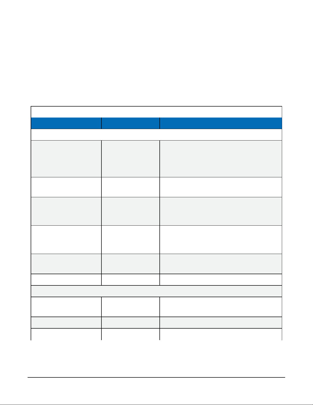
For most applications, the default settings (Table 6-3 (p. 9)) allow the LevelVUE B10 to work out
of the box with only minor changes such as setting an offset. Settings can be changed by using
the keypad/display, the SDI-12 extended commands, or Modbus commands (Modbus register
map (p. 30)).
Table 6-3: LevelVUE B10 user options
Option Default value Comments/quick reference
Stage setup menu options
Displays the last measured stage value.
Stage N/A
Enter a floating point value of the
desired stage reading to automatically
calculate the stage offset
Units Feet
Slope 2.3067 (feet)
Offset 0.0
Num Stage Digits 2
Measure Average 5 s Range is 1 to 255 s
Bubbler setup menu options
60 bubbles per
Bubble Rate
minute
Purge Pressure 60 psi Purge-pressure range is 30 to 90 psi
Options are feet, meters, inches, centimeters,
millimeters, psi, and user-defined
Automatically set based on stage units.
If stage units are user defined, this
option accepts a floating point value.
Either automatically calculated based on the
stage entry or entered as a floating point
value
Digit range is 2 to 4. Sets the number of digits
to the right of the decimal for the stage value
Bubble-rate range is
30 to 120 bubbles per minute
Purge Sustain 10 s Purge-sustain range is 0 to 60 s
LevelVUE™B10 Water-Level Bubbler 9
Page 14
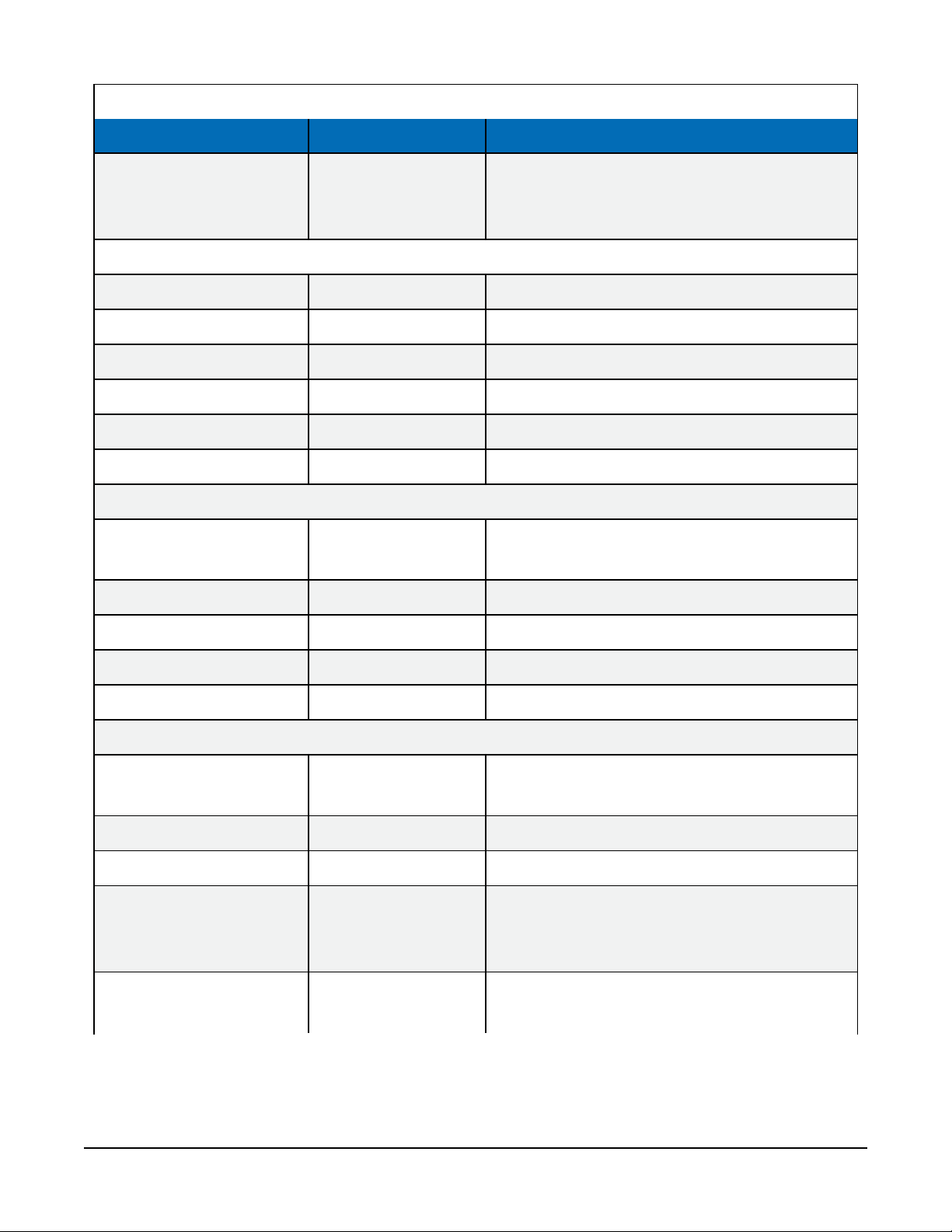
Table 6-3: LevelVUE B10 user options
Option Default value Comments/quick reference
Range is 0 to 30 days
Auto Purge 0
System setup menu options
Date Does not reset System date in format of yyyy/mm/dd
Time Does not reset System time in format of hh:mm:ss
Display Sleep 5 minutes Range is 1 to 15 minutes
Display Brightness 80% Range is 10 to 100%
Temperature Units ° C Options are ° C or ° F
Reset to Defaults N/A Resets options to default values
Communications setup menu options
0 disables auto purge
1 to 30 = once a day to once every 30 days
SDI-12 Address 0
ModbusAddress 1 Possible addresses: 1 to 247.
RS-485Baud Rate 19200 bps Standard baud rates from 9600 to 115200 bps
RS-485 Parity even Options are even, odd, none
RS-485 Stop Bits 2 Options are 1 or 2
Diagnostics/test menu options
Status Errors N/A
Test Line Noise N/A Press Enter to perform a line noise test
Test Line Leak N/A Press Enter to perform a line leak test
Reset Min / Max N/A
Possible addresses: 0 to 9 (Standard),
A to Z, a to z
Displays error (Table 7-1 (p. 24) or
none if no errors are detected
Press Enter to reset the min and max
battery values to the current battery value
level
Min Battery Voltage N/A
Displays the minimum voltage detected
on the battery
LevelVUE™B10 Water-Level Bubbler 10
Page 15
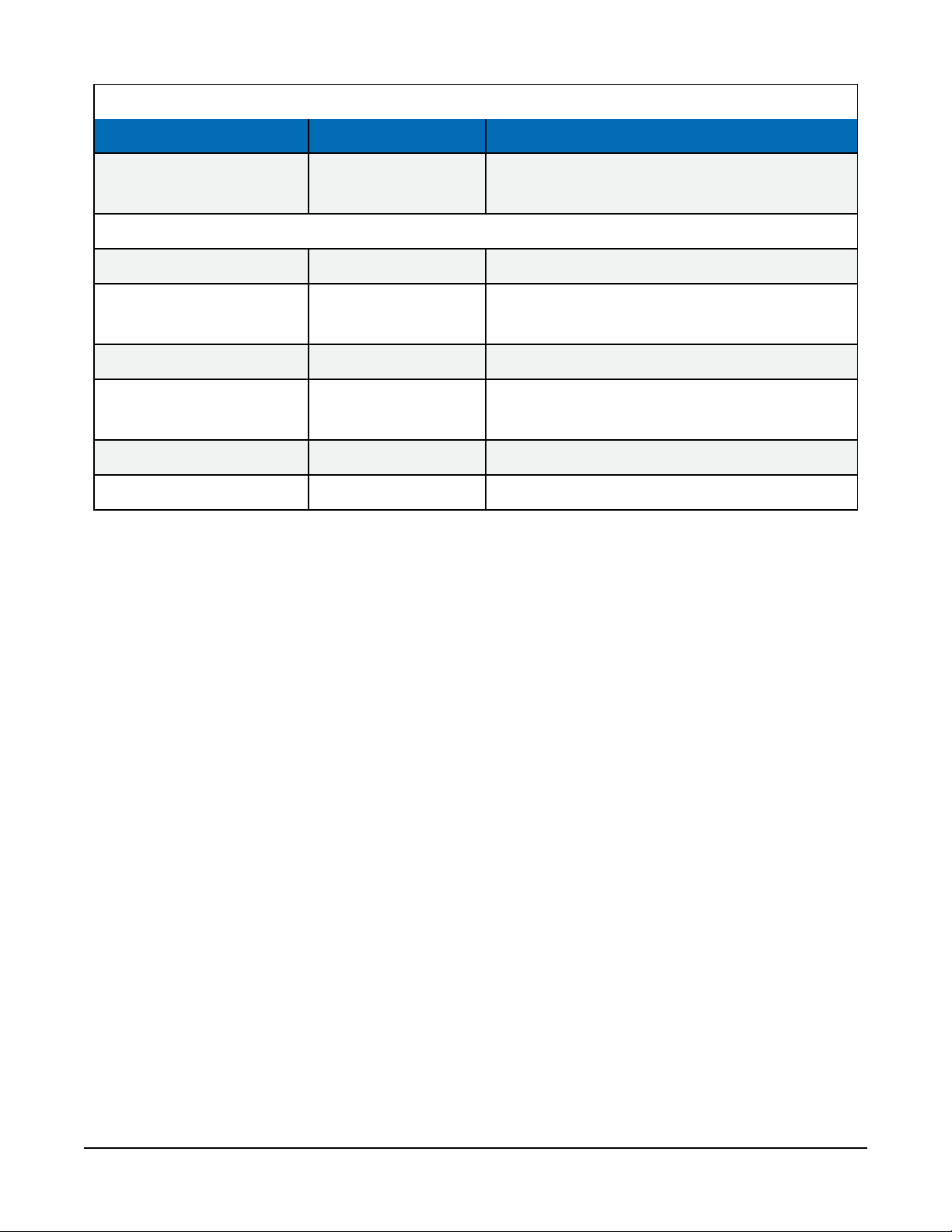
Table 6-3: LevelVUE B10 user options
Option Default value Comments/quick reference
Max Battery Voltage N/A
System information menu options
Clear Purge Counter N/A Press Enter to reset purge counter to zero
Clear System Reset
N/A
Counter
Purge Counter N/A Displays the number of purges since last reset
System Reset Counter N/A
Sensor SN N/A Displays the sensor serial number
OS version N/A Displays the current operating system version
Displays the maximum voltage detected
on the battery
Press Enter to reset the system reset counter to
zero
Displays the number of system resets since last
reset
6.5 Setup using keypad/display
The LevelVUE B10 includes a keypad/display to set up, make measurements, and troubleshoot
the unit. Although the LevelVUE B10 can be completely setup using the SDI-12 or Modbus
protocols, using the keypad/display is more convenient for setting up and testing. Open the
enclosure lid to access the keypad/display.
LevelVUE™B10 Water-Level Bubbler 11
Page 16
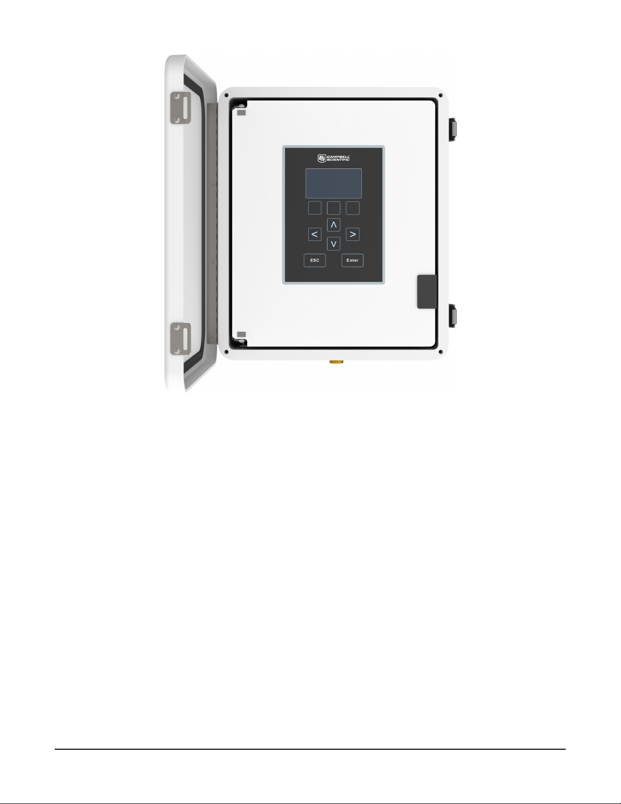
FIGURE 6-2. LevelVUE B10 keypad/display
Press the right arrow key to open a menu and show the available options. Fixed values are shown
next to an equal sign (=), while editable options are displayed inside square brackets ([ ]). To edit
a menu, press the right arrow key at the chosen menu and use the up and down arrow keys to
make the changes to the parameter.
The following example shows the process for changing the stage setting.
1. Press the down arrow key to move to the setup screen.
2. Press the right arrow key to access the stage setup screen.
3. Press the right arrow key and press the Enter key.
4. Use the right and left arrow keys to move the cursor to the digit you want changed, then
use the up and down arrow keys to change the number.
5. Press Enter when the number is changed to the correct value.
LevelVUE™B10 Water-Level Bubbler 12
Page 17

6.6 Campbell Scientific data logger programming
A data logger or RTU can remotely control and retrieve LevelVUE B10 data. Programming basics
for Campbell Scientific CRBasic data loggers are provided in the following sections. If using
another manufacturer's data logger or RTU, refer to their documentation for programming
information. An SDI-12 program example for a Campbell Scientific data logger is provided in
Example program (p. 46).
6.6.1 SDI-12 programming
The SDI12Recorder() instruction is used to measure a LevelVUE B10 configured for SDI-12
measurements. This instruction sends a request to the sensor to make a measurement and then
retrieves the measurement from the sensor. See SDI-12 measurement and extended commands
(p. 27) for more information.
For most data loggers, the SDI12Recorder() instruction has the following syntax:
SDI12Recorder(Destination, SDIPort, SDIAddress, “SDICommand”, Multiplier,
Offset, FillNAN, WaitonTimeout)
For the SDIAddress, alphabetical characters need to be enclosed in quotes (for example,
“A”). Also enclose the SDICommand in quotes as shown. The Destination parameter must
be an array. The required number of values in the array depends on the command (see Table 7-2
(p. 28)).
FillNAN and WaitonTimeout are optional parameters (refer to CRBasic Help for more
information).
6.6.2 RS-485 programming
The RS-485 output can be directly read by a CR6-series, CR1000X-series, or Modbus RTU RS-485
network. Other Campbell Scientific data loggers can use an MD485 multidrop interface to read
the RS-485 output. Refer to the MD485 manual for information about using the MD485.
A CR6 or CR1000X data logger programmed as a Modbus Master can retrieve the values stored in
the Input Registers (). To do this, the CRBasic program requires SerialOpen() followed by
ModbusMaster(). The SerialOpen instruction has the following syntax:
SerialOpen (ComPort, Baud, Format, TXDelay, BufferSize, Mode)
LevelVUE™B10 Water-Level Bubbler 13
Page 18

The Format parameter is typically set to logic 1 low; even parity, one stop bit, 8 data bits. The
Mode parameter should configure the ComPort as RS-485 half-duplex, transparent.
The ModbusMaster() instruction has the following syntax:
ModbusMaster (Result, ComPort, Baud, Addr, Function, Variable, Start, Length,
Tries, TimeOut, [ModbusOption])
The Addr parameter must match the sensor Modbus address. To collect all of the values, the
Start parameter needs to be 1 and the Length parameter needs to correspond with the
register count (see Modbus register map (p. 30). For ModbusOption parameter use 2, which
means the Modbus variable array is defined as a 32-bit float or a Long, with no reversal of the
byte order (ABCD).
6.7 Field installation
6.7.1 Site selection 14
6.7.2 Enclosure mounting 14
6.7.3 Desiccator installation 15
6.7.4 Orifice line and conduit installation 17
6.7.1 Site selection
The site selection is often based on the type of water being measured. Water in rivers and
streams will act differently than in lakes and reservoirs. In rivers and streams, choose a location
where the water velocity remains constant regardless of water levels. Care must also be taken to
prevent errors caused by drawdown and buildup such as around a bridge pier. In lakes and
reservoirs, wind can cause wave action and buildup on the face of the dam or other structure.
Select a location that will be less affected by these conditions.
6.7.2 Enclosure mounting
1. Choose a location that is accessible for servicing electrical connections and plumbing
fittings, but will not get jarred or shifted during operation.
2. Place the enclosure at the desired height with connectors pointing down so that moisture
or condensation that could collect on the connectors do not access the inner components
of the equipment.
LevelVUE™B10 Water-Level Bubbler 14
Page 19
3. Secure the enclosure to a wall or flat surface using user-supplied bolts. The enclosure
includes holes at the top and bottom of the enclosure for mounting the LevelVUE B10.
4. Route a 14 AWG copper wire from the enclosure grounding lug to an earth ground.
6.7.3 Desiccator installation
WARNING:
Not using a desiccator will void your warranty.
An external desiccator is required to dry the compressor intake air and prevent accumulation of
moisture in the tank, manifold, and other areas in the system. Campbell Scientific offers a
desiccator kit (FIGURE 6-3 (p. 16)), which is recommended for use with the LevelVUE B10.
LevelVUE™B10 Water-Level Bubbler 15
Page 20
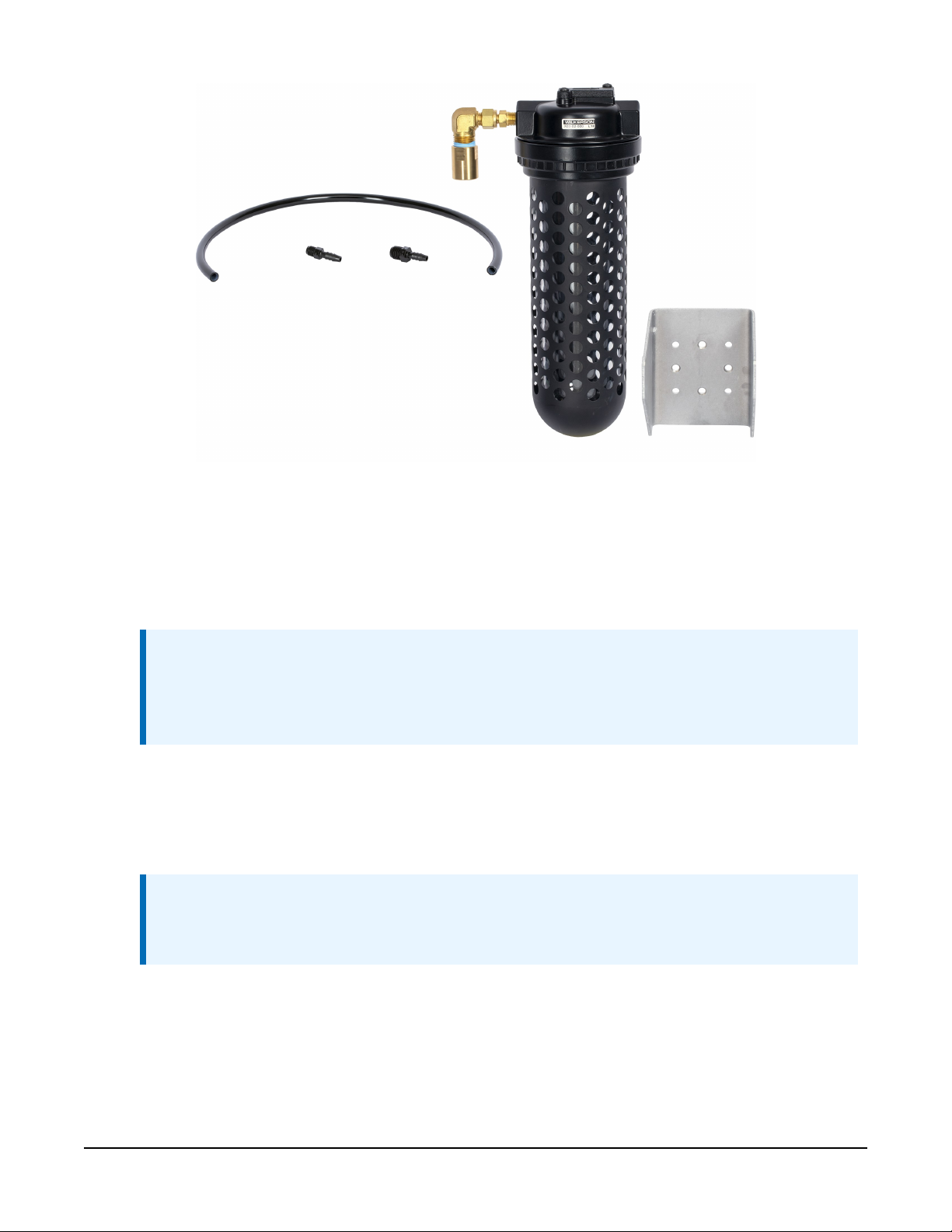
FIGURE 6-3. Desiccator kit (indicating desiccant not shown)
Desiccator installation procedure:
1. Use the desiccator kit bracket to mount the desiccator as close to the LevelVUE B10
enclosure as possible.
NOTE:
Campbell Scientific offers a long desiccant tube if the desiccator needs to be located
farther away from the bubbler than normal, such as when air must be drawn from
outside the main enclosure.
2. Insert the threaded end of the 1/4-inch NPT barbed fitting included in the desiccator kit
into the desiccator connector.
3. Insert the threaded end of the air-intake 1/8-inch NPT barbed fitting into the Inlet port of
the LevelVUE B10, then connect the desiccator output tubing to both barbed fittings.
NOTE:
The LevelVUE B10 is shipped with a plug inserted in the intake port that needs to be
removed before inserting the 1/8-inch NPT barbed fitting.
LevelVUE™B10 Water-Level Bubbler 16
Page 21
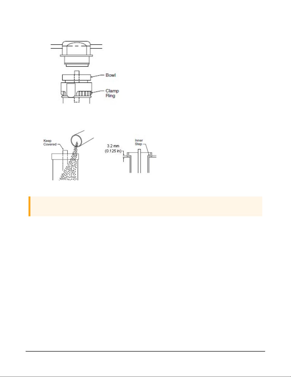
4. Loosen the clamp ring on the desiccator and remove the bowl from the top housing.
5. Pour desiccant into the bowl; shake and tap bowl while filling to settle desiccant. Fill to
3mm (0.1in) below inner step of bowl.
6. Replace the bowl and bowl guard.
CAUTION:
Ensure that the clamp ring is securely locked in place before operating the unit.
6.7.4 Orifice line and conduit installation
To ensure accurate data, consider the following while siting and installing the orifice line:
l Install the orifice line in an area that will remain relatively calm. A stilling well is a good
option.
l Install the orifice line at a continuous downward slope from the LevelVUE B10 to the outlet,
avoiding swells, dips, and depressions.
l If possible, use one continuous orifice line to eliminate junctions or splices, which are
potential sources for leaks. Campbell Scientific offers orifice line that comes in 152m
(500ft) rolls, which suits most applications. If a continuous line is not possible, install the
junction or splice in a serviceable enclosure.
l Do not use quick connect fittings as these tend to leak.
LevelVUE™B10 Water-Level Bubbler 17
Page 22

l Protect the orifice line inside a 53mm (2-inch) steel conduit that is fastened to a
permanent and secure structure such as bridge pier, cement slab, or pilings.
l Avoid sharp bends in the conduit during installation. Sharp bends can result in kinks and
make installation more difficult.
l If the orifice line crosses a road, ensure that it is buried deep enough to prevent the line
from being crushed from vehicles using the road.
l Use an orifice-line cap to secure the orifice line output to the conduit. The orifice-line cap
offered by Campbell Scientific works for most installations. Refer to Orifice-line outlet types
(p. 38) for more information.
l Mount the orifice-line outlet vertically or slightly turned to the horizontal position and
perpendicular to the primary direction of flow. Refer to Orifice-line outlet orientation (p.
37) for more information.
The installation procedure follows:
1. Secure the conduit to a permanent and secure structure such as bridge pier, cement slab,
or pilings.
2. Route the orifice line inside the conduit.
3. Insert the orifice line into the Swagelok® compression fitting of the orifice outlet cap and
tighten the fitting (FIGURE 6-4 (p. 18)).
FIGURE 6-4. Orifice outlet cap
4. Loosen the big nut on the outside of the cap to allow the brass fitting to freely turn inside
the end cap.
5. Screw the end cap onto the 2-inch conduit. While screwing on the end cap, ensure that the
brass fitting does not move, which means the orifice line is not being twisted.
6. Once the end cap is secure, tighten the big nut on the end of the cap to secure the brass
fitting.
7. At the bubbler end, cut off excessive amount of orifice line.
LevelVUE™B10 Water-Level Bubbler 18
Page 23

8. Remove the plug from the Swagelok® fitting on the Outlet port.
9. Insert this orifice line into the Swagelok® compression fitting on the bubbler outlet and
tighten.
10. Secure any extra orifice line and orient it horizontally to avoid low points in the line.
7. Operation
7.1 Principles of operation 19
7.2 Keypad/display menu 20
7.3 SDI-12 measurement and extended commands 27
7.4 Modbus register map 30
7.5 Secured orifice line 35
7.6 Long orifice lines 37
7.7 Orifice-line outlet orientation 37
7.8 Orifice-line outlet types 38
7.1 Principles of operation
A bubbler operates by establishing a constant flow of air that is independent of the water level
(pressure) above the orifice line outlet. As the water level rises, the bubbler increases the pressure
in the tank to maintain a constant flow of bubbles. The water level is proportional to the pressure
required to move the air to the end of the orifice line. The bubbles indicate air at the end of the
line:
Pressure = ρ x g x h
Where:
Pressure (Pa)
ρ = density of the water (1000 kg/m3)
g = gravitational constant (9.8 m/s2)
h = height of the column of water (m)
100 kPa = 14.5 psi
LevelVUE™B10 Water-Level Bubbler 19
Page 24

7.2 Keypad/display menu
LevelVUE™B10 Water-Level Bubbler 20
Page 25

7.2.1 Stage setup
Stage: Displays the last measured stage. The user can enter a new stage and the system will
calculate a new offset based on the new stage.
Units: Units used to report the water level. Default is feet. When changed, the slope value is
automatically adjusted to provide water level measurements in the selected units. The userdefined option allows the user to manually enter a slope that does not match a predefined value.
Slope: Slope or conversion factor used to convert the raw psi reading into units of feet, meters, or
user-defined. If the Units option is set to user-defined, the slope can be changed to any value.
Offset: Difference between the water-level reference point and the level of the orifice-line outlet.
The user can enter the offset here. Alternatively, the user can enter a value for the Stage [xx.xx]
option and the LevelVUE B10 will calculate the correct offset.
Num Stage Digits: Number of digits used to display the stage value on the display. Default is 2.
Measure Average: Averaging time (in seconds) that the LevelVUE B10 uses to make a water level
measurement. Default is 5 seconds. Entering a longer averaging time can reduce noise caused by
water conditions such as waves or turbulence. Please note that the actual measurement time will
be 3 to 4 seconds longer than this value due to internal processing.
7.2.2 Bubbler setup
Bubble Rate: Rate of the airflow in the orifice line. Range is 30 to 120 bubbles per minute. The
rate is affected by the orifice-outlet size, orientation of the outlet, and the pressure difference in
the tank and line, etc. With a lower bubble rate, the air compressor may run less frequently.
Higher rates allow the system to respond more quickly to water level increases. Default setting is
60 bubbles per minute, which is sufficient for most applications. With a standard 1/8 ID orifice
LevelVUE™B10 Water-Level Bubbler 21
Page 26

line and a 1/4inch outlet, 60 bubbles per minute tracks a rise of 1 foot per 10 seconds. A rise
faster than 1 foot per 10 seconds requires a faster bubble rate.
Purge Pressure: Default is 60 psi. Regularly use a high-pressure purge to keep the orifice line
clear of debris. Silty streams or installations with long orifice lines may require a higher purge
pressure. More frequent purges are also recommended for silty streams.
Purge Sustain: Length of time (in seconds) that the compressor runs after reaching the purge
pressure and opening the purge valve. Default is 10. Increasing the purge sustain time may make
the purge more efficient and may increase the air flow.
Auto Purge: Automatic purge rate (in days). The automatic purge rate can be once a day to once
every 30 days. A setting of 0 disables automatic purging.
NOTE:
See the note following the Date and Time options (System setup (p. 22)) for more
information on the Auto Purge function.
7.2.3 System setup
Date: A correct date is needed for the Auto Purge option. Set this up when you initially set up
the system.
Time [HH:MM:SS]: The correct time is needed for the Auto Purge option. Set this up when you
initially set up the system or if it changes.
NOTE:
The Date and Time are only used for the Auto Purge option and should be set to the local
time. The Auto Purge occurs immediately after the measurement at or just after 12:00 noon,
local time. This schedule allows the line to stabilize before the next measurement and ensures
that the purge occurs during the day light hours when the battery is at a higher charge level
when using solar power. If the Date and Time are not set, the Auto Purge occurs at an
unpredictable schedule.
Display Sleep: Amount of time (in minutes) that the keypad can be idle before the display turns
off. Default is 5 minutes.
Dsp Brightness: Brightness or contrast of the display. Default is 80.
LevelVUE™B10 Water-Level Bubbler 22
Page 27

Temperature Units: Options are degree C and F.
Reset to Defaults ?: Resets to default values (Table 6-3 (p. 9)).
NOTE:
This option does not reset the date, time, minimum and maximum battery voltage, and error
and status flags.
CAUTION:
Resetting the LevelVUE B10 to the defaults changes the SDI-12 and Modbus addresses to the
defaults. Therefore, SDI-12 or Modbus communications will be unresponsive until the data
logger program is changed to match the default addresses or the SDI-12 or Modbus address
in the LevelVUE B10 is changed to match the data logger.
7.2.4 Communication setup
SDI-12 Address: Valid addresses are 0 through 9, a through z, and A through Z. Each SDI-12
device connected to the same SDI-12 signal terminal needs a unique SDI-12 address. Default is 0.
Modbus Address: Each Modbus device connected to the same RS-485 terminals needs a unique
Modbus address. Default is 001.
RS485 Baud: Baud rate for the RS-485 port used for Modbus operations. Default is 19200.
RS485 Parity: Setting must match the data logger or Modbus RTU setting. Default is Even.
RS485 Stop Bits: Number of stop bits used for the RS-485 (Modbus) interface. Default is 2.
7.2.5 Diagnostic/Test
LevelVUE™B10 Water-Level Bubbler 23
Page 28

Status Errors
Displays True if errors are detected or None if errors are not detected. If errors are detected, press
the Enter key and the first error will be displayed (Table 7-1 (p. 24)).
The error code returned with an SDI-12 command is the sum of the weighted value for each error.
Weighted values were chosen to ensure the sum is unique for each error combination. For
example, if error 1 and error 6 were detected, the SDI-12 error code will be 33 (1+32).
Some errors or status messages are automatically cleared once the error is resolved. The more
serious errors remain active until they are manually reset by the user.
Table 7-1: Error flag descriptions
Error
number
1 1 Error
2 2 Error
3 4 Error Temperature value exceeded range.
4 8 Error
5 16 Error
6 32 Error Tank offset calculation timeout.
7 64 Error
SDI-12
Weighted
Value
Type
Error description and
recommended action
Line sensor exceeded pressure range.
Check for plugged line.
Tank sensor exceeded pressure range.
Check for plugged line.
Pressure not increasing (stalled
compressor or leak).
Pressure not decreasing. Check for
obstruction or plugged orifice line.
Tank offset calculation out of range
error.
Message
displayed on
screen
Line Sen
Rnge Err
Tank Sen
Rnge Err
Temperature
Rnge Err
Pressure Up
Err
Pressure Dwn
Err
Tank Offset
TO
Tank Offset
Error
Reset
Manual
Manual
Manual
Manual
Manual
Manual
Manual
8 128 Error
9 256 Error
Compressor over current. Check
battery/charge system.
RTC battery low voltage warning.
Change the RTC battery.
LevelVUE™B10 Water-Level Bubbler 24
Compressor
Manual
Over Amps
RTC Battery
Manual
Low
Page 29

Table 7-1: Error flag descriptions
Error
SDI-12
Weighted
number
Value
13 4096 Status
14 8192 Status
15 16384 Status
16 32768 Status
Test Line Noise
Type
Error description and
recommended action
Input supply or battery voltage is below
10.6V, which is the voltage needed to
power the compressor. The LevelVUE
B10 will not do an auto or manual purge
while condition persists.
Compressor stall or leak detected.
Check battery/charge system.
Compressor on time exceeded time out.
Observe tank pressure and power for
proper operation during purge.
Compressor flow on time exceeded time
out.
Message
displayed on
screen
Low Battery Auto
Stalled Pump
or Leak
Purge Pump
On TO
Flow Pump
On TO
Reset
Auto
Auto
Auto
Checks the integrity of the orifice line regarding noise and stability. Initially, the LevelVUE B10
measures stage, atmospheric pressure, and temperature. This takes about 7 seconds. The
LevelVUE B10 stores the initial stage measurement as both the max and min values. The screen
displays the difference between the max and min values, which is 0.000 for the initial
measurement.
After the initial measurements, the LevelVUE B10 measures stage using the original atmospheric
and temperature readings at a 1 second measurement rate. The max and min values are updated
as new max or min values are detected and the difference is displayed on the screen. If the line is
secure, the difference between the max and min values is small and will not significantly increase.
A large difference that continues to increase indicates a problem with the orifice line.
Test Line Noise can be used while installing a new orifice line to find the best orifice line outlet
position. Temporarily position the outlet and run this test to see if the position is relatively quiet.
Reposition the line if it is too noisy. After the line is repositioned, restart the test.
Test Line Noise can be used to test the bubbler. Disconnect the orifice line and run the test. The
difference between the max and min values should be less than the resolution of the system
(Table 5-1 (p. 4)). While doing this test, ensure there isn't any breeze or air movement around the
outlet port, which can cause noise in the system.
LevelVUE™B10 Water-Level Bubbler 25
Page 30

Test Line Leak
Leaks are one of the biggest problems with bubbler systems. Normally, the leak is at the fitting
that connects the orifice line to the bubbler or somewhere between that fitting and the end of
the orifice line. Tightening the orifice line fitting an 1/8 turn often resolves the problem. When a
leak exist, the stage value will remain equal to the offset value.
However, a small percentage (1%) of the leaks are in the bubbler itself. This test verifies the
bubbler is not leaking. To use this test, disconnect the orifice line and replace it with the plug
shipped on the LevelVUE B10 outlet fitting. This test turns on the compressor and fills the tank to
a pressure slightly below the pressure range of the bubbler. The system lets the pressures in the
system equalize for about 15 seconds before displaying the max pressure, min pressure, and the
difference of the max and min pressures. The test displays a count-down timer and runs for about
5 minutes (300 seconds). The difference value may rise while the system is equalizing, but after 15
seconds, the difference should be less than 0.15. After 1 or 2 minutes, the difference should be
stable. Contact Campbell Scientific if the difference value continues to rise significantly.
Field Cal Check
Use this option in conjunction with an off-the-shelf field calibration tool to regularly verify the
field calibration. Some agencies require this. Refer to Field calibration check (p. 59) for more
information.
Reset Max/Min
Use this option at the end of a site visit to reset the minimum and maximum battery voltage
detected. At the beginning of the next site visit look at the value of the minimum and maximum
battery voltages detected since the last site visit to help determine the status of the battery and
the charging system.
Min Batt V. XX.XX
Displays the minimum battery voltage detected since the last time this was reset. A low reading
indicates a weak battery or an inadequate charging system.
Max Batt V. XX.XX
Displays the maximum battery voltage detected since the last time this was reset. A high reading
may indicate a faulty regulator or other charging system problem.
LevelVUE™B10 Water-Level Bubbler 26
Page 31

7.2.6 System information
Clear Purge CNTR: Clears the purge counter. To see if the system is purging as often as expected,
use this option at the end of a site visit to set the purge counter to zero. At the beginning of the
next site visit, check that the purge counter has a value that corresponds with the expected
number of purges.
Clear SysRST CNTR: Sets the system reset counter to 0. See Sys RST CNTR that follows.
Purge CNTR = X: Number of orifice-line purges since the last reset.
Sys RST CNTR = X: Number of system resets. If the Clear SysRST CNTR is used at the end of each
site visit, this will show the number of resets since the last visit. System resets indicate that the
battery may be weakening, inadequate power wiring, or the charge system needs servicing.
Sensor SN = XXXX: Serial number of the LevelVUE B10. A support person may ask for this number
if the LevelVUE B10 needs servicing.
OS Ver = X.XX: Operating system (OS) version number currently loaded into the system.
Campbell Scientific recommends using the latest OS. Use Campbell Scientific Device
Configuration Utility to update the OS. Also, if service is needed, a support person may ask for
the OS version number.
7.3 SDI-12 measurement and extended commands
The LevelVUE B10 responds to the SDI-12 commands shown in Table 7-2 (p. 28). Because of
delays, the M! commands require, the measurement scans should be 10 seconds or more. The C!
commands follow the same pattern as the M! commands with the exception that they do not
require the data logger to pause its operation until the values are ready.
NOTE:
SDI-12 sensor support (p. 48) describes the SDI-12 commands. Additional SDI-12 information
is available at www.sdi-12.org .
LevelVUE™B10 Water-Level Bubbler 27
Page 32

Table 7-2: LevelVUE B10 SDI-12 measurement and extended commands
SDI-12 command
(a is the sensor address)
aM!, aC!, aMc!, or aCc!
aXWSR=rrr.rr!
Where, rrr.rr= stage
reference
Values returned or function Description
1. Stage (m or ft)
2. Line pressure (psi)
3. Tank pressure (psi)
4. Temperature (°C)
5. Battery voltage (VDC)
6. Error code
1
The stage crest time is a time
offset. It is the number of
seconds in the past from the
current measurement that
the crest stage value was
detected.
7. Stage crest (m or ft)
8. Stage crest time
Write stage value
Use to change stage
reference to rrr.rr in
configured units.
Write stage units
Use to change the stage
units, where:
0=in
aXWSU=x!
Where, x = units value
aXRSU!
aXWSS=s.sssssss!
Where, s.sssssss=2.3066587
or 0.7032496
1=ft
2=mm
3=cm
4=m
5=psi
6=user-specified (used with
the aXWSS=s.sssssss!
command)
Read stage units
Write stage slope Use to change the units for
stage. This command is only
used when the stage units
are set to user-specified
(aXWSU=6!).
Feet = 2.3066587 (default)
Meters = 0.7032496
LevelVUE™B10 Water-Level Bubbler 28
Page 33

Table 7-2: LevelVUE B10 SDI-12 measurement and extended commands
SDI-12 command
(a is the sensor address)
aXRSS! Read stage slope.
aXWCO=o.oo!
Where, o.oo= stage offset
aXRCO!
aXWBR=bb!
Where, bb= bubble rate
aXRBR!
aXWPP=pp!
Where, pp= purge pressure
Values returned or function Description
Write calculated stage offset
Read calculated stage offset.
Write bubble rate (bubbles per
minute)
Read bubble rate Bubbles per minute
Write purge pressure (psi). Use to change the purge
Use to update stage offset.
Use to change the bubble
rate.
Default = 60 bubbles per
minute
pressure.
Default = 60 psi
Range: 30 to 90 psi
aXRPP!
aXP!
aXWPA=tt!
Where, tt= purge time
aXRPA!
aXWSD=dd!
Where, dd= digits
aXRSD!
Read purge pressure (psi)
Initiate bubbler purge sequence
Write purge assist time
(seconds)
Read purge assist time (seconds)
Write stage digits Use to set the number of
Read stage digits
Use to set the time the
compressor runs during the
purge sequence after the
purge valve opens.
Default = 20 s
digits to the right of the
decimal for the stage value.
Default = 2
LevelVUE™B10 Water-Level Bubbler 29
Page 34

Table 7-2: LevelVUE B10 SDI-12 measurement and extended commands
SDI-12 command
(a is the sensor address)
aXWMT=tt!
Where, tt= stage mean time
aXRMT!
aXWAP=tt!
Where, tt= auto purge
setting
aXRAP! Read auto-purge setting (days)
aXATZ!
aXTEST!
Values returned or function Description
Write stage mean time (seconds) Use to increase or decrease
Read stage mean time (s)
Write auto-purge setting (days) 0 = off (no auto-purge)
Reset sensor to defaults (Default
settings (p. 9))
1. Stage (m or ft)
2. Line pressure (psi)
3. Tank pressure (psi)
4. Temperature (°C)
5. Battery voltage (VDC)
6. Error code
1
the averaging time of stage
measurements
Default = 5 s
Range = 1 to 30 days
Use to put the sensor into a
continuous output mode
with data being transmitted
to the terminal every second.
Any command will interrupt
the continuous output mode
and resume normal
operation.
aXHELP!
1
The error code is the sum of the weighted value for each error. The errors and weighted values are listed in
the Error flag descriptions table.
Returns the supported SDI-12
commands by the
LevelVUE B10
7.4 Modbus register map
The Modbus data type is 32-bit float with no reversal. Table 7-3 (p. 31) provides the input register
map (function code 4). Table 7-4 (p. 32) provides the holding register map (function code 3).
LevelVUE™B10 Water-Level Bubbler 30
Page 35

Table 7-3: ModBus input register map
Label Input Register Value stored
Stage 30001 Current stage measurement value
Temperature 30003 Current temperature measurement
Tank pressure 30005 Current tank pressure
Line pressure 30007
Battery voltage 30009
Min battery volt 30011
Max battery volt 30013 Maximum battery voltage
Purge count 30015 Number of purge events since counter was reset
System resets 30017 Number of system resets since counter was reset
Purge date 30019 Last purge date in the form of YYMMDD.00
Purge time 30021 Last purge time in the form of hhmmss.00
Status bits 30023
Current line pressure used to calculate stage with
current slope and offset values
Current battery measurement. Updated every 30
seconds or during the stage measurement
Minimum battery voltage (normally detected while
compressor was running)
256 = RTC battery low voltage warning. Change the
RTC battery.
4096 = Input supply or battery voltage is below
10.6V, which is the voltage needed to power the
compressor. The LevelVUE B10 will not do an auto or
manual purge while condition persists.
8192 = Compressor stall or leak detected. Check
battery/charge system.
16384 = Compressor on time exceeded time out.
Observe tank pressure and power for proper
operation during purge.
32768 = Compressor flow on time exceeded time out.
LevelVUE™B10 Water-Level Bubbler 31
Page 36

Table 7-3: ModBus input register map
Label Input Register Value stored
Crest max 30025
Crest offset 30027
Table 7-4: Modbus holding register map
Label
Stage Ref 40001 Last stage value
Stage Units 40003
Holding
register
(function code 3)
Returns a number
from 0 to 6
indicating the units,
where:
0 inches
1 feet (default)
2 millimeters
3 centimeters
4 meters
5 psi
6 User-defined
Maximum crest stage observed between two
successive stage measurements
This is a time offset. It is the number of seconds in the
past from the current measurement that the crest
stage value was detected.
Read
Write (function code 16)
Measures and recalculates the offset
required to make the current stage
value equal to the value written to this
register
Enter a value in a range of 0 to 6,
where:
0 inches
1 feet (default)
2 millimeters
3 centimeters
4 meters
5 psi
6 User-defined (must enter a stage
slope value described in the following
row)
LevelVUE™B10 Water-Level Bubbler 32
Page 37

Table 7-4: Modbus holding register map
Label
Holding
register
Stage Slope 40005
Stage Offset 40007
Date 40009
Read
(function code 3)
Returns the
following values
depending on the
stage units:
27.68 inches
2.3067 feet (default)
703.08 millimeters
70.308 centimeters
0.70308 meters
1 psi
User-defined
Returns the stage
offset value.
Returns the system
date in the format of
YYMMDD.00
Write (function code 16)
To write a user-defined value the stageunits register must first be set to 6.
Enter the stage offset value.
Enter the system date, as a float, in the
format of YYMMDD.00
Time 40011
Measurement
40013
Average Duration
Temperature Units 40015
Bubble Rate 40017
Returns the system
time in the format of
hhmmss.00
Returns the
measurement
averaging time in
seconds.
Returns:
0 Celsius
1 Fahrenheit
Returns the bubble
rate. Range is 30 to
120
Enter the system time, as a float, in the
format of hhmmss.00
Enter the measurement averaging time
in seconds. The range is from 1 to 255.
Enter 0 for Celsius or 1 for Fahrenheit
Enter the bubble rate. Range is 30 to
120
LevelVUE™B10 Water-Level Bubbler 33
Page 38

Table 7-4: Modbus holding register map
Label
Holding
register
Purge Pressure 40019
Purge Sustain
40021
Duration
Auto Purge Interval 40023
Display Sleep 40025
Display Brightness 40027
Read
(function code 3)
Returns purge
pressure in psi.
Range is 30 to 90.
Returns purge
sustain time in
seconds. Range is 0
to 30.
Returns auto purge
interval in days.
Returns display sleep
timeout period in
minutes.
Returns the display
brightness option.
Range is 10 to 100
Write (function code 16)
Enter the purge pressure in psi. Range is
30 to 90.
Enter purge sustain time in seconds.
Range is 0 to 30.
Enter auto purge interval in days. Range
is 0 to 30 days
Enter display sleep timeout period in
minutes. Range is 1 to 15.
Enter the display brightness between 10
and 100. Value will be rounded to
nearest ten.
Reset Status Values 40029 Returns 0.00
Returns the Modbus
Modbus Address 40031
device address
Entering a non-zero value such as 1.00
will reset status values to the following:
Purge count: 0
Minimum battery value: current battery
voltage
Maximum battery value: current battery
voltage
System Resets: 0
Enter a new Modbus address. Range is 1
to 247.
LevelVUE™B10 Water-Level Bubbler 34
Page 39

Table 7-4: Modbus holding register map
Label
Holding
register
Measure Now 40033
Purge Now 40035
Read
(function code 3)
Returns a 0.00 or
time till current
measurement is
ready in seconds.
Returns a 0 when not
purging. Returns a 1
if in the process of
running a purge.
Write (function code 16)
Entering a non-zero value causes the
unit to make a stage measurement. The
register will then hold the number of
seconds till the measurement is
complete. Once the register becomes
zero, new measurement values will be
available in the following Input
Registers:
Stage, Line Pressure , Tank pressure,
Battery Voltage , and Temperature.
Writing a non-zero value (1.00) will
cause system to purge.
7.5 Secured orifice line
Campbell Scientific recommends protecting the orifice line inside a 53mm (2-inch) steel conduit.
Fasten the conduit to a permanent and secure structure such as bridge pier, cement slab, or
pilings to prevent movement. If the conduit moves, the orifice line can stretch, kink, or break. A
stretched orifice line restricts the air flow, which increases pressure, causing erroneously high
stage measurements. A broken orifice line leaks. If a leak is present, the measured stage value
will be the same or close to the offset value. Kinks create erratic data. These same problems can
also occur if the orifice line crosses a road and the line is not properly protected from the traffic
on the road.
If the outlet of the orifice line shifts but is still stable, the vertical shift will be seen in the data.
This problem occurs when the orifice line mount near the outlet has been hit by large debris such
as a log. Scour can also cause mounts to shift. FIGURE 7-1 (p. 36) shows the sharp rise in water
level, possibly indicating that the orifice line shifted down by about 0.20 feet.
LevelVUE™B10 Water-Level Bubbler 35
Page 40

FIGURE 7-1. Sharp rise in water level indicating orifice line shift.
The orifice outlet cap must be secure the keep the outlet of orifice line from moving. If the outlet
of the orifice line shifts vertically, the water level measurement will show a sharp rise or fall.
Horizontal movement can create an unwanted pressure or vacuum on the line causing noise in
the data. This type of noise is often called painting. The frequent fluctuations in gageheight in
FIGURE 7-2 (p. 37) could be due to a loose orifice end cap. Regardless of the source of noise, the
measurement averaging time can be increased to minimize the noise in the data.
LevelVUE™B10 Water-Level Bubbler 36
Page 41

FIGURE 7-2. Data painting
The conduit should be installed to withstand or protected against large debris such as logs or
other items that may be in the water from jarring or loosening the conduit from its mounts.
7.6 Long orifice lines
When purging long orifice lines, the friction in the line is significant and the purge is less
effective. When the orifice line is longer than a few hundred feet, always set the Purge Pressure
setting to the highest value and set the Purge Duration option to its maximum value. This helps
keep the line free from silting or other growth at the outlet.
7.7 Orifice-line outlet orientation
Undesired pressures on the orifice line can affect the water level measurement. The main source
of the unwanted pressures is from the flow of the water and the orientation of the outlet. This
can be a positive or negative pressure and will change based on water levels and velocities. For
example, if the orifice line outlet is slightly horizontal and pointing upstream, as the water flow
pushes against the outlet, it will create an artificially high pressure. If the outlet is facing
downstream, a vacuum will be imposed on the line. Build up and draw down around a bridge
pier will also affect the pressure on the orifice line. Eddie currents are much less predictable and
affect the pressure on the orifice line. Wave action is another source of unwanted pressures on
the orifice line.
LevelVUE™B10 Water-Level Bubbler 37
Page 42

In most cases, the unwanted pressured due to water flow will have less impact on the orifice line
when mounted vertically or slightly turned to the horizontal position and perpendicular to the
primary direction of flow. However, a bubble can form on a vertically oriented orifice line outlet
that adds to the water depth. In still water, this increase can be as much as 0.003m (0.01ft). In
moving water, the bubble is ripped off the end of the outlet before it has time to grow. In a
system that has an error specification of 0.02% or 0.002m (0.007ft) of water for a 15psi unit, this
unwanted pressure can double that error percentage if the outlet is not properly oriented.
Bubbler systems are designed to reduce or eliminate the noise caused by the unwanted pressures
and the bubble growth. In most cases, the default measurement averaging time of 1 second is
sufficient, but if noise is still noticed in the data and the line is stable, increasing this averaging
time to 5 to 10 seconds will reduce noise in the system.
7.8 Orifice-line outlet types
Campbell Scientific offers an orifice-line outlet that consists of a 1/4-inch ID fitting mounted in
the end cap for the 53mm (2-inch) conduit. This type of outlet can be mounted vertically or
slightly horizontal, and responds quickly to small rises in the water level. The LevelVUE B10
average bubble rate is based on using this type of orifice outlet cap.
An end cap with a large air chamber may be better for sites with quick rises in water levels (faster
than 0.3m/10s (1ft/10s)), heavy wave action, or silting issues. With the standard outlet, water
pushes up the orifice line at a rate equal to the rise of the water. Depending on the level change,
it may take a few to several seconds for the system to start bubbling again. Measurements made
during this time will be lower than the actual level. An end cap with a large air chamber greatly
reduces the errors caused by the rapid and large rises in water levels because it acts as an
integrator.
In shallow streams, silt may cover the outlet when the river bottom shifts. Silt can restrict the air
flow, causing data errors. Silt is less likely to restrict the air flow when the air chamber is large.
The timed purge option should also be activated when in silty environments.
Drawbacks to an end cap with a large air chamber include that it must be mounted horizontal, it
may be harder to protect from large debris, and it takes more time for the system to fill the air
chamber. Measurements made while the air chamber is filling will be inaccurate. Noisier data
also occurs during small rises in the water level.
LevelVUE™B10 Water-Level Bubbler 38
Page 43

8. Maintenance and troubleshooting
NOTE:
All factory repairs and recalibrations require a returned material authorization (RMA) and
completion of the “Statement of Product Cleanliness and Decontamination” form. Refer to
the Assistance page at the end of this manual for more information.
8.1 Replacing desiccant 39
8.2 Lithium battery replacement 40
8.3 Plugged orifice outlet 41
8.4 Cold weather 42
8.5 Preventing or fixing orifice-line leaks 42
8.6 Updating operating system 42
8.7 Troubleshooting 43
8.1 Replacing desiccant
Regularly replace the desiccant. Desiccant replacement frequency depends on the humidity of
the site and the size of the desiccator. For new installations, Campbell Scientific recommends
checking the desiccant at least once a month. After a few months, users can adjust how often
they check the desiccant. Replacement silica gel desiccant is available at: www.campbellsci.com .
Desiccant replacement procedure:
1. Remove power from the LevelVUE B10.
2. Depressurize the input line.
LevelVUE™B10 Water-Level Bubbler 39
Page 44

3. Loosen the clamp ring on the desiccator and remove the bowl from the top housing.
4. Pour out used desiccant and dispose of it according to the safety data sheet originally
shipped with the desiccator kit.
5. Open new desiccant container.
6. Pour desiccant into the bowl; shake and tap bowl while filling to settle desiccant. Fill to
3mm (0.1in) below inner step of bowl.
7. Replace the bowl and bowl guard.
CAUTION:
Ensure that the clamp ring is securely locked in place before operating the unit.
8.2 Lithium battery replacement
A 3V coin-cell lithium battery maintains the system clock when there is no power to the
LevelVUE B10. Campbell Scientific recommends replacing the lithium every 2 to 3 years, or more
frequently when operating continuously in high temperatures. The battery should be replaced if
its voltage falls below 2.4VDC.
NOTE:
When the LevelVUE B10 is connected to 12 VDC, there is no power draw from the lithium
battery.
LevelVUE™B10 Water-Level Bubbler 40
Page 45

Lithium battery replacement procedure:
1. Open the swing panel located at the bottom-left edge of the plate that protects the circuit
board below the USB port (FIGURE 8-1 (p. 41)).
FIGURE 8-1. Lithium battery location
2. Remove the old battery.
3. Insert the new battery with the positive side up (plus sign facing the metal plate).
NOTE:
Although inserting the battery incorrectly will not damage the system, the lithium battery will
be drained quickly.
DANGER:
Misuse of the internal lithium battery can cause severe injury. Do not recharge, disassemble,
heat above 100°C (212°F), solder directly to the cell, incinerate, or expose contents to water.
Dispose of spent lithium batteries properly.
8.3 Plugged orifice outlet
The orifice line outlet can become plugged from silt build up, moss growth, or debris. Often
these conditions occur over a long period of time. Silt or moss build up restricts air flow that can
increase the water level readings. This restriction in air flow is not consistent causing the data to
fluctuate.
LevelVUE™B10 Water-Level Bubbler 41
Page 46

Manually purge the system during each site visit to keep the orifice line free from blockage.
When the water is lower and the outlet is accessible, inspect the outlet for growth. Clean the
outlet with a wire brush, as needed. Use a pipe cleaner or heavy stiff wire such as a coat hanger
to remove buildup from inside the outlet. Purge the system while cleaning the orifice outlet to
help keep the line cleared.
Relocate the outlet if it is constantly being covered in silt.
8.4 Cold weather
In cold and humid weather areas, disable the purge feature during the cold season. If in a cold
and humid area, the desiccant is less effective in preventing frozen particles from accessing areas
of the system that could cause problems when the frozen particles melt.
Ice formed at the surface of the water can compress the orifice line and restrict the air flow. Water
in the conduit that freezes has no place to expand, causing erroneously high water-level
measurements.
8.5 Preventing or fixing orifice-line leaks
Because bubblers contain several tubes, fittings, and valves, leaks are one of the biggest
problems with bubbler systems. Campbell Scientific designed and manufactured the LevelVUE
B10 to ensure these internal components are installed properly and to be leak free. However, care
must also be taken when connecting and installing the orifice line to avoid leaks. Do not use
quick connect fittings as these tend to leak, and avoid extra fittings when possible. Try to use one
continuous orifice line to eliminate junctions or splices, which are potential sources for leaks.
Campbell Scientific offers orifice line that comes in 500-foot rolls, which suits most applications.
The rare application that requires orifice lines longer than 500 feet should include the junction or
splice in a serviceable enclosure.
Find leaks in orifice lines or connectors by using a mixture of water and dish soap. Apply a small
amount of the dish-soap mixture to fittings that are suspected of leaking. The dish-soap mixture
will bubble where the fitting is leaking. Always wipe the fitting off with a dry rag.
8.6 Updating operating system
Campbell Scientific Device Configuration Utility is used to update the operating system (OS). The
Device Configuration Utility is available as a download on www.campbellsci.com . It is
included in installations of LoggerNet, PC400, or RTDAQ.
LevelVUE™B10 Water-Level Bubbler 42
Page 47

1. Open the Device Configuration Utility.
2. In the Device Type box, type LevelVUE B10 and click on LevelVUE B10
3. Before connecting this product to your computer for the first time, click the Install USB
Driver button to install the driver.
4. Apply power (+12VDC) to the Power connector.
5. Connect a USB cable between one of your computer USB ports and the USB port on the
device .
6. In the left panel, select the appropriate serial port. If you browse for the serial port, it
should be identified with the LevelVUE B10 designation in the browse dialogue.
7. Click the Start button below.
8. A file open dialogue box will appear that will allow you to select the file to be sent. When
you have selected the file, click the OK button.
9. After the operating system has been successfully sent, the device will reboot and should be
ready to use in approximately 30 seconds.
CAUTION:
Do not remove power for at least 30 seconds.
8.7 Troubleshooting
Table 8-1 (p. 44) provide symptoms, causes, and solutions for problems. Most problems are
caused by orifice line or programming issues. A line noise test can be used to determine whether
noisy data is caused by an orifice line issue or a problem with the LevelVUE B10. Refer to
Diagnostic/Test (p. 23) for more information.
LevelVUE™B10 Water-Level Bubbler 43
Page 48

Table 8-1: Symptoms, possible causes, and solutions
Symptom Possible cause Solution
A leak is in the orifice line between
Stage is always
the same value as
the offset
Data is painting
the water surface and the LevelVUE
B10. A leak in this area can result in a
line pressure value of zero. This causes
the stage value to equal the offset
value because of the equation used to
calculate stage:
Stage = Pressure • Slope + offset
1. Orifice line outlet is not stable.
Any movement in the orifice line
outlet will have a direct effect on
the data.
2. Moisture in the orifice line can
create friction for the air flow
and cause abnormal pressures in
the line that affect the pressure
caused by water depth.
3. Waves, choppy water,
fluctuations in water flow
creates different pressures and
vacuums on the orifice line
outlet, which creates noise in
the line.
4. Loose orifice end cap
Use water/dish soap mixture to look
for leaks in the orifice line. Normally
the leak will be at one of the fittings
connecting the orifice line to the
LevelVUE B10. See Preventing or
fixing orifice-line leaks (p. 42).
1. Ensure that the orifice line is
inside a conduit that is
fastened to a permanent and
secure structure such as bridge
pier, cement slab or pilings.
The conduit should be
protected from large debris
such as logs to prevent the
debris from jarring or
loosening the conduit from its
mounts. See Secured orifice
line (p. 35).
2. Regularly purge the line to
help keep moisture out. Also
make sure there are no low
points in the orifice line that
allow moisture to collect.
3. Increase the averaging time by
5 to 10 seconds.
4. Tighten end cap.
An unexpected
sharp rise or fall
in water level
data
The orifice-line outlet mount may
Clear debris and secure the mount.
Ensure that the conduit is installed to
have shifted because of large debris
withstand or is protected from large
such as a log hitting the orifice line
debris that may jar or loosen the
mount near the outlet or because of
conduit from its mounts. . See
scour.
Secured orifice line (p. 35).
LevelVUE™B10 Water-Level Bubbler 44
Page 49

Table 8-1: Symptoms, possible causes, and solutions
Symptom Possible cause Solution
Make sure the battery is sufficiently
Compressor
Battery may not have sufficient
seems to run
voltage to run the compressor.
slow.
charged to handle the needed power
requirements to run the compressor.
Check the charging system. Clean
the solar panel
Water level
values drift low at
night
All LevelVUE B10
output values
read 0
First value reads
NAN and all
other values read
0 or never
change from one
measurement to
another.
The battery may be weak and only
able to turn on the compressor when
the solar charging system is also
supplying power.
1. No SDI12Recorder()
instruction in data logger
program.
2. Conditional statement that
triggers reading is not
evaluating as true
1. LevelVUE B10 SDI-12 address
does not match address
specified in data logger program
2. LevelVUE B10 is not connected
to the SDI-12 terminal specified
in data logger program
3. LevelVUE B10 not being
powered
Check the battery voltage and
replace the battery if needed. Check
the charging system. Clean the solar
panel
1. Add SDI12Recorder()
instruction to data logger
program
2. Check logic of conditional
statement that triggers
readings
1. Change LevelVUE B10 SDI-12
address or modify program so
that they match
2. Connect wire to correct
terminal or modify program to
match wiring
3. Make sure the LevelVUE B10 is
wired correctly and matches
the data logger program
Readings erratic,
including NANs
and 9999999s
Connect each SDI-12 device to
a different U or C terminal
Multiple devices with same
or give them unique SDI-12
SDI-12 address sharing same
addresses. Ensure that you revise
U or C terminal
the data logger program to
account for these changes.
LevelVUE™B10 Water-Level Bubbler 45
Page 50

Appendix A. Example program
Table A-1 (p. 46) provides wiring for the SDI-12 example program (CRBasic Example 1 (p. 46)).
Table A-1: Wiring for SDI-12 example program
LevelVUE B10 terminal Function CR1000X terminal Power supply
SDI-12 Data SDI-12 signal C1
SDI-12 G Ground ⏚
12Vdc + Power 12V
12Vdc - Power ground G
CRBasic Example 1: CR1000X program measuring the LevelVUE B10 using SDI-12
'CR1000X Series Data Logger
'Declare variables and Units
Public BattV
Public PTemp_C
Public LVData(8)
'Rename the variable names
Alias LVData(1)=Stage
Alias LVData(2)=Line_psi
Alias LVData(3)=Tank_psi
Alias LVData(4)=LVB10_Temp
Alias LVData(5)=LVB10_Batt
Alias LVData(6)=LVB10_ErrorCode
Alias LVData(7)=Crest_Stage
Alias LVData(8)=Crest_Tm_Offs
Units BattV=Volts
Units PTemp_C=Deg C
Units Stage=feet
Units Line_psi=psi
Units Tank_psi=psi
Units LVB10_Temp=Deg C
Units LVB10_Batt=volts
Units LVB10_ErrorCode=code
LevelVUE™B10 Water-Level Bubbler 46
Page 51

CRBasic Example 1: CR1000X program measuring the LevelVUE B10 using SDI-12
Units Crest_Stage=feet
Units Crest_Tm_Offs=seconds
'Define a data table
DataTable(MainData,True,-1)
DataInterval(0,5,Min,10)
Sample (1,Stage,FP2)
Sample (1,Line_psi,FP2)
Sample (1,Tank_psi,FP2)
Sample (1,LVB10_Temp,FP2)
Sample (1,LVB10_Batt,FP2)
Sample (1,LVB10_ErrorCode,FP2)
Sample(1,Crest_Stage,FP2)
Sample(1,Crest_Tm_Offs,FP2)
Sample(1,BattV,FP2)
Sample(1,PTemp_C,FP2)
EndTable
'Main program
BeginProg
'Main scan
Scan(5,Sec,1,0)
'Default CR1000X data logger Voltage measurement 'BattV'
Battery(BattV)
'Default CR1000X data logger Wiring Panel Temperature measurement 'PTemp_C'
PanelTemp(PTemp_C,60)
'LevelVUEB10 Water-Level Continuous Flow Bubbler measurements
If TimeIntoInterval(0,5,Min) Then
SDI12Recorder (LVData(),C1,0,"M!",1.0,0)
EndIf
'Call the data tables and store data
CallTable MainData
NextScan
EndProg
LevelVUE™B10 Water-Level Bubbler 47
Page 52

Appendix B. SDI-12 sensor support
SDI-12, Serial Data Interface at 1200 baud, is a protocol developed to simplify sensor and data
logger compatibility. Only three wires are necessary — serial data, ground, and 12 V. With unique
addresses, multiple SDI-12 sensors can connect to a single SDI-12 terminal on a Campbell
Scientific data logger.
This appendix discusses the structure of SDI-12 commands and the process of querying SDI-12
sensors. For more detailed information, refer to version 1.4 of the SDI-12 protocol, available at
www.sdi-12.org .
For additional information, refer to the SDI-12 Sensors | Transparent Mode and SDI-12 Sensors |
Watch or Sniffer Mode videos.
B.1 SDI-12 command basics
SDI-12 commands have three components:
l Sensor address (a) – a single character and the first character of the command. Use the
default address of zero (0) unless multiple sensors are connected to the same port.
l Command body – an upper case letter (the “command”), optionally followed by one or
more alphanumeric qualifiers.
l Command termination (!) – an exclamation mark.
An active sensor responds to each command. Responses have several standard forms and always
terminate with <CR><LF> (carriage return and line feed). Standard SDI-12 commands are listed
in Table B-1 (p. 48).
Table B-1: Campbell Scientific sensor SDI-12 command and response set
Name Command
Acknowledge Active
Send Identification
Start Verification
a!
aI!
aV!
Response
a<CR><LF>
allccccccccmmmmmmvvvxxx...xx
<CR><LF>
atttn <CR><LF>
1
LevelVUE™B10 Water-Level Bubbler 48
Page 53

Table B-1: Campbell Scientific sensor SDI-12 command and response set
Name Command
Address Query
Change Address
Start Measurement
Start Measurement
and Request CRC
Start Concurrent Measurement
StartConcurrentMeasurement
and Request CRC
Send Data
Continuous Measurement
?!
aAb!
aM!
aM1!...aM9!
aMC!
aMC1!...aMC9!
aC!
aC1!...aC9!
aCC!
aCC1!...aCC9!
aD0!...aD9!
aR0!...aR9!
Response
a<CR><LF>
b<CR><LF>
atttn<CR><LF>
atttn <CR><LF>
atttnn<CR><LF>
atttnn<CR><LF>
a<values><CR><LF> or
a<values><CRC><CR><LF>
a<values><CR><LF>
1
Continuous Measurement
and Request CRC
Extended Commands
1
Information on each of these commands is given in the following sections.
aRC0!...aRC9!
aXNNN!
a<values><CRC><CR><LF>
a<values><CR><LF>
B.1.1 Acknowledge active command (a!)
The Acknowledge Active command (a!) is used to test a sensor on the SDI-12 bus. An active
sensor responds with its address.
B.1.2 Send identification command (al!)
Sensor identifiers are requested by issuing command aI!. The reply is defined by the sensor
manufacturer but usually includes the sensor address, SDI-12 version, manufacturer’s name, and
sensor model information. Serial number or other sensor specific information may also be
included.
aI!
a Sensor SDI-12 address
allccccccccmmmmmmvvvxxx...xx<CR><LF>
ll SDI-12 version number (indicates compatibility)
LevelVUE™B10 Water-Level Bubbler 49
Page 54

cccccccc 8-character vendor identification
mmmmmm 6 characters specifying the sensor model
vvv 3 characters specifying the sensor version (operating system)
xxx…xx
<CR><LF>
Source: SDI-12: A Serial-Digital Interface Standard for Microprocessor-Based Sensors (see References).
Up to 13 optional characters used for a serial number or other specific
sensor information that is not relevant for operation of the data logger
Terminates the response
B.1.3 Start verification command (aV!)
The response to a Start Verification command can include hardware diagnostics, but like the aI!
command, the response is not standardized.
Command: aV!
Response: atttn<CR><LF>
a = sensor address
ttt = time, in seconds, until verification information is available
n = the number of values to be returned when one or more subsequent D! commands are issued
B.1.4 Address query command (?!)
Command ?! requests the address of the connected sensor. The sensor replies to the query with
the address, a. This command should only be used with one sensor on the SDI-12 bus at a time.
B.1.5 Change address command (aAb!)
Multiple SDI-12 sensors can connect to a single SDI-12 terminal on a data logger. Each device on
a single terminal must have a unique address.
A sensor address is changed with command aAb!, where a is the current address and b is the
new address. For example, to change an address from 0 to 2, the command is 0A2!. The sensor
responds with the new address b, which in this case is 2.
NOTE:
Only one sensor should be connected to a particular terminal at a time when changing
addresses.
LevelVUE™B10 Water-Level Bubbler 50
Page 55

B.1.6 Start measurement commands (aM!)
A measurement is initiated with the M! command. The response to each command has the form
atttn<CR><LF>, where
a = sensor address
ttt = time, in seconds, until measurement data is available. When the data is ready, the sensor
notifies the data logger, and the data logger begins issuing D commands.
n = the number of values returned when one or more subsequent D commands are issued. For
the aM! command, n is an integer from 0 to 9.
When the aM! is issued, the data logger pauses its operation and waits until either it receives the
data from the sensor or the time, ttt, expires. Depending on the scan interval of the data logger
program and the response time of the sensor, this may cause skipped scans to occur. In this case
make sure your scan interval is longer than the longest measurement time (ttt).
Table B-2: Example aM! sequence
0M!
00352<CR><LF>
0<CR><LF>
0D0!
0+.859+3.54<CR><LF>
The data logger makes a request to sensor 0 to start a measurement.
Sensor 0 immediately indicates that it will return two values within
the next 35 seconds.
Within 35 seconds, sensor 0 indicates that it has completed the
measurement by sending a service request to the data logger.
The data logger immediately issues the first D command to collect
data from the sensor.
The sensor immediately responds with the sensor address and the two
values.
B.1.7 Start concurrent measurement commands (aC!)
A concurrent measurement (aC!) command follows the same pattern as the aM! command with
the exception that it does not require the data logger to pause its operation, and other SDI-12
sensors may take measurements at the same time. The sensor will not issue a service request to
notify the data logger that the measurement is complete. The data logger will issue the aD0!
command during the next scan after the measurement time reported by the sensor has expired.
To use this command, the scan interval should be 10 seconds or less. The response to each
command has the form atttn<CR><LF>, where
a = the sensor address
ttt = time, in seconds, until the measurement data is available
LevelVUE™B10 Water-Level Bubbler 51
Page 56

nn = the number of values to be returned when one or more subsequent D commands are
issued.
See the following example. A data logger has three sensors wired into terminal C1. The sensors
are addresses X, Y, and Z. The data logger will issue the following commands and receive the
following responses:
Table B-3: Example aC! sequence
XC!
X03005<CR><LF>
YC!
Y04006<CR><LF>
ZC!
Z02010<CR><LF>
ZD0!
The data logger makes a request to sensor X to start
a concurrent measurement.
Sensor X immediately indicates that it will have 5
(05) values ready for collection within the next 30
(030) seconds.
The data logger makes a request to sensor Y to start
a concurrent measurement.
Sensor Y immediately indicates that it will have 6
(06) values ready for collection within the next 40
(040) seconds.
The data logger makes a request to sensor Z to start
a concurrent measurement.
Sensor Z immediately indicates that it will have 10
values ready for collection within the next 20 (020)
seconds.
After 20 seconds have passed, the data logger starts
the process of collecting the data by issuing the first
D command to sensor Z.
Z+1+2+3+4+5+6+7+8+9+10<CR><LF>
XD0!
X+1+2+3+4+5<CR><LF>
Sensor Z immediately responds with the sensor
address and the 10 values.
10 seconds later, after a total of 30 seconds have
passed, the data logger starts the process of
collecting data from sensor X by issuing the first D
command.
The sensor immediately responds with the sensor
address and the 5 values.
LevelVUE™B10 Water-Level Bubbler 52
Page 57

Table B-3: Example aC! sequence
YD0!
Ten seconds later, after a total of 40 seconds have
passed, the data logger starts the process of
collecting data from sensor Y by issuing the first D
command.
Y+1+2+3+4+5+6<CR><LF>
The sensor immediately responds with the sensor
address and the 6 values.
B.1.8 Start measurement commands with cyclic redundancy check (aMC! and aCC!)
Error checking is done by using measurement commands with cyclic redundancy checks (aMC!
or aCC!). This is most commonly implemented when long cable lengths or electronic noise may
impact measurement transmission to the data logger. When these commands are used, the data
returned in response to D or R commands must have a cyclic redundancy check (CRC) code
appended to it. The CRC code is a 16-bit value encoded within 3 characters appended before the
<CR><LF>. This code is not returned in the data table but checked by the data logger as it
comes. The code returned is based on the SDI-12 protocol. See the SDI-12 communication
specification for version 1.4 available at www.sdi-12.org to learn more about how the CRC
code is developed.
B.1.9 Stopping a measurement command
A measurement command (M!) is stopped if it detects a break signal before the measurement is
complete. A break signal is sent by the data logger before most commands.
A concurrent measurement command (C!) is aborted when another valid command is sent to the
sensor before the measurement time has elapsed.
B.1.10 Send data command (aD0! … aD9!)
The Send Data command requests data from the sensor. It is issued automatically with every type
of measurement command (aM!, aMC!, aC!, aCC!). When the measurement command is aM!
or aMC!, the data logger issues the aD0! command once a service request has been received
from the sensor or the reported time has expired. When the data logger is issuing concurrent
commands (aC! or aCC!), the Send Data command is issued after the required time has elapsed
(no service request will be sent by the sensor). In transparent mode (see SDI-12 transparent mode
(p. 55) ), the user asserts this command to obtain data.
Depending on the type of data returned and the number of values a sensor returns, the data
logger may need to issue aD0! up to aD9! to retrieve all data. A sensor may return up to 35
LevelVUE™B10 Water-Level Bubbler 53
Page 58

characters of data in response to a D command that follows an M! or MC! command. A sensor
may return up to 75 characters of data in response to a D command that follows a C! or CC!
command. Data values are separated by plus or minus signs.
Command: aD0! (aD1! … aD9!)
Response: a<values><CR><LF> or a<values><CRC><CR><LF>
where:
a = the sensor address
<values> = values returned with a polarity sign (+ or –)
<CR><LF> = terminates the response
<CRC> = 16-bit CRC code appended if data was requested with aMC! or aCC!.
B.1.11 Extended commands
Many sensors support extended SDI-12 commands. An extended command is specific to a make
of sensor and tells the sensor to perform a specific task. They have the following structure.
Responses vary from unit to unit. See the sensor manual for specifics.
Command: aXNNNN!
The command will start with the sensor address (a), followed by an X, then a set of optional
letters, and terminate with an exclamation point.
Response: a<optional values><CR><LF>
The response will start with the sensor address and end with a carriage return/line feed.
B.1.12 SDI-12 version 1.4 identify measurement commands and responses
Version 1.4 compliant sensors must respond to identify commands for each type of measurement
command and each parameter with a command. The broad identify commands return how many
variables will be returned with a given measurement command and the time it will take the
sensor to respond. The specific identify parameter commands will return a SHEF code, the
measurement units, and the type of measurement (sample, count, or average). For more
information see the SDI-12 version 1.4 specification.
(http://sdi-12.org/current_specification/SDI-12_version-1_4-May-1-2017.pdf)
LevelVUE™B10 Water-Level Bubbler 54
Page 59

Table B-4: Supported V1.4 Commands (Command Information)
Type of Command
Identify measurement for M
commands
Identify measurement for C
commands
Identify measurement for V
commands
1
Where a is theSDI-12 address; ttt is the response time; and n is the number of values returned
Table B-5: Supported V1.4 Commands (Parameter Identification) in the LevelVUE B10
Parameter
Stage aIM_001!, aIC_001! a,HG,xx,sample;<CR><LF>
Line pressure aIM_002!, aIC_002! a,LP,PSI,sample;<CR><LF>
aIM!, aIMC! atttn<CR><LF>
aIC!, aICC! atttnn<CR><LF>
aIV! atttn<CR><LF>
Command
Command
1
1
Sensor Response
Sensor Response
1
1
Tank pressure aIM_003!, aIC_003! a,TP,PSI,sample;<CR><LF>
Temperature aIM_004!, aIC_004! a,TMP,y,sample;<CR><LF>
Battery voltage aIM_005!, aIC_005! a,VB,V,sample;<CR><LF>
Error code aIM_006!, aIC_006! a,ERROR,CODE,sample;<CR><LF>
Peak stage aIM_007!, aIC_007! a,HG2,xx,sample;<CR><LF>
Peak stage offset time aIM_008!, aIC_008!
1
Where a is the SDI-12 address; xx is either ft or m; and y is either C or F.
a,HG2_TIME,SEC,sample;
<CR><LF>
B.2 SDI-12 transparent mode
System operators can manually interrogate and enter settings in probes using transparent mode.
Transparent mode is useful in troubleshooting SDI-12 systems because it allows direct
communication with probes. Data logger security may need to be unlocked before activating the
transparent mode.
Transparent mode is entered while the computer is communicating with the data logger through
a terminal emulator program. It is accessed through Campbell Scientific data logger support
LevelVUE™B10 Water-Level Bubbler 55
Page 60

software or other terminal emulator programs. Data logger keyboards and displays cannot be
used.
The terminal emulator is accessed by navigating to the Tools list in PC400 or the Datalogger list
in the Connect screen of LoggerNet.
Watch videos/sdi12-sensors-transparent-mode from our website.
Data loggers from other manufacturers will also have a transparent mode. Refer to those manuals
on how to use their transparent mode.
The following examples show how to enter transparent mode and change the SDI-12 address of
an SDI-12 sensor. The steps shown in Changing an SDI-12 address (p. 56) are used with most
Campbell Scientific data loggers.
B.2.1 Changing an SDI-12 address
This example was done with a CR1000X, but the steps are only slightly different for CR6, CR3000,
CR800-series, CR300-series, CR1000 data loggers.
1. Connect an SDI-12 sensor to the CR1000X.
2. In LoggerNet Connect, under Datalogger, click Terminal Emulator. The terminal emulator
window opens.
3. Under Select Device, located in the lower left side of the window, select the CR1000X
4. Click Open Terminal.
5. Select All Caps Mode.
6. Press Enter until the data logger responds with the CR1000X> prompt.
LevelVUE™B10 Water-Level Bubbler 56
Page 61

7. Type SDI12 and press Enter.
8. At the Select SDI12 Port prompt, type the number corresponding to the control port where
the sensor is connected and press Enter. The response Entering SDI12 Terminal indicates
that the sensor is ready to accept SDI-12 commands.
9. To query the sensor for its current SDI-12 address, type ?! and press Enter. The sensor
responds with its SDI-12 address. If no characters are typed within 60 seconds, the mode is
exited. In that case, simply type SDI12 again, press Enter, and type the correct control port
number when prompted.
10. To change the SDI-12 address, type aAb!, where a is the current address from the previous
step and b is the new address. Press Enter. The sensor changes its address and responds
with the new address. In the following example, the sensor address is changed from 0 to B.
11. To exit SDI-12 transparent mode, click Close Terminal.
LevelVUE™B10 Water-Level Bubbler 57
Page 62

NOTE:
The transparent mode for the CR6, CR3000, CR800-series, CR300-series, and CR1000 data
loggers is similar to that shown for the CR1000X.
B.3 References
SDI-12 Support Group. SDI-12: A Serial-Digital Interface Standard for Microprocessor-Based
Sensors – Version 1.4. River Heights, UT: SDI-12 Support Group, 2017. http://www.sdi-
12.org/current_specification/SDI-12_version-1_4-Dec-1-2017.pdf .
LevelVUE™B10 Water-Level Bubbler 58
Page 63

Appendix C. Field calibration check
Some agencies require the calibration to be verified on a specified schedule. The procedure for
verifying the calibration uses an off-the-shelf field calibration tool, such as Druck DPI611 (FIGURE
C-1 (p. 59)) or DPI612 series.
FIGURE C-1. DPI611 calibration tool
1. Go to the site.
2. Press the arrows on the LevelVUE B10 keypad to go to the Diagnostic/Test menu and select
the Field Cal Check option.
LevelVUE™B10 Water-Level Bubbler 59
Page 64

3. When the following screen appears, disconnect the orifice line and connect the LevelVUE
B10 outlet to the calibration tool.
Run Field Cal Check?
Attach Field
Cal. Tool.
YESNO
4. Select YES to start the test. The following message will be briefly displayed:
Run Field Cal Check?
Setting Up…
Please Wait
Timeout Counter 899
5. At this point, the purge valve is activated to allow pressures in the system to equalize
quickly. Also, the built-in compressor is disabled allowing the pressure to be controlled
solely by the calibration tool. The test will time out after about 15 minutes. Once the system
pressures equalize the following screen is displayed:
Run Field Cal
Line PSI: x.xxx
Timeout Counter 321
STOP TCRST
6. While the test is running, the pressure measured by the LevelVUE B10 is displayed on the
screen. This value should be very close to the value displayed on the calibration tool. Keep
in mind, it may take a few seconds for the system to equalize after the pressure is changed.
The test can be stopped at any time by pressing the soft key STOP or reset to run longer by
pressing the soft key TCRST (Timeout Counter Reset). While the test is running, adjust the
pressure as needed to verify proper operation.
CAUTION:
Do not pressurize the system higher than the rated pressure range.
It is good practice to test the pressure at each end of the range and at a mid-point. For
example, on a 0 to 30 psi bubbler, test at about 0.100 psi, 15.000 psi, and at 29.900 psi. To
pass the test, the bubbler and the calibrator readings need to be within the system
accuracy. For example, a 30 psi unit with a maximum error of ±0.02% passes the calibration
LevelVUE™B10 Water-Level Bubbler 60
Page 65

test if the bubbler value is within ±0.006 psi (30 psi x 0.02% = 0.006 psi) of the calibrator
value.
NOTE:
The worst-case error is additive. The bubbler accuracy is 0.02% and the calibrator
accuracy is typically 0.01%. Therefore, the worst case error is 0.03% (0.02% + 0.01%). For
a 30 psi unit, this is ±0.009 psi (0.0003 x 30).
7. Once the test is stopped or the timeout expires, the unit will ask if the field calibrator tool
has been removed. After removing the calibrator, reconnect the LevelVUE B10 orifice line.
The timeout counter defaults to 30 seconds to provide enough time to switch the line.
Run Field Cal
Field Cal Tool
Removed?
Timeout Counter 28
EXIT TCRST
8. After the test, reconnect the orifice line and purge the line to ensure water is out of the
orifice line.
LevelVUE™B10 Water-Level Bubbler 61
Page 66

Limited warranty
Products manufactured by Campbell Scientific are warranted by Campbell Scientific to be free
from defects in materials and workmanship under normal use and service for twelve months from
the date of shipment unless otherwise specified on the corresponding product webpage. See
Product Details on the Ordering Information pages at www.campbellsci.com . Other
manufacturer's products, that are resold by Campbell Scientific, are warranted only to the limits
extended by the original manufacturer.
Refer to www.campbellsci.com/terms#warranty for more information.
CAMPBELL SCIENTIFIC EXPRESSLY DISCLAIMS AND EXCLUDES ANY IMPLIED WARRANTIES OF
MERCHANTABILITY OR FITNESS FOR A PARTICULAR PURPOSE. Campbell Scientific hereby
disclaims, to the fullest extent allowed by applicable law, any and all warranties and conditions
with respect to the Products, whether express, implied or statutory, other than those expressly
provided herein.
Page 67

Assistance
Products may not be returned without prior authorization.
Products shipped to Campbell Scientific require a Returned Materials Authorization (RMA) or
Repair Reference number and must be clean and uncontaminated by harmful substances, such as
hazardous materials, chemicals, insects, and pests. Please complete the required forms prior to
shipping equipment.
Campbell Scientific regional offices handle repairs for customers within their territories. Please
see the back page for the Global Sales and Support Network or visit
www.campbellsci.com/contact to determine which Campbell Scientific office serves your
country.
To obtain a Returned Materials Authorization or Repair Reference number, contact your
CAMPBELL SCIENTIFIC regional office. Please write the issued number clearly on the outside of
the shipping container and ship as directed.
For all returns, the customer must provide a “Statement of Product Cleanliness and
Decontamination” or “Declaration of Hazardous Material and Decontamination” form and
comply with the requirements specified in it. The form is available from your CAMPBELL
SCIENTIFIC regional office. Campbell Scientific is unable to process any returns until we receive
this statement. If the statement is not received within three days of product receipt or is
incomplete, the product will be returned to the customer at the customer’s expense. Campbell
Scientific reserves the right to refuse service on products that were exposed to contaminants that
may cause health or safety concerns for our employees.
Page 68

Safety
DANGER — MANY HAZARDS ARE ASSOCIATED WITH INSTALLING, USING, MAINTAINING, AND WORKING ON OR AROUND TRIPODS, TOWERS,
AND ANY ATTACHMENTS TO TRIPODS AND TOWERS SUCH AS SENSORS, CROSSARMS, ENCLOSURES, ANTENNAS, ETC. FAILURE TO PROPERLY
AND COMPLETELY ASSEMBLE, INSTALL, OPERATE, USE, AND MAINTAIN TRIPODS, TOWERS, AND ATTACHMENTS, AND FAILURE TO HEED
WARNINGS, INCREASES THE RISK OF DEATH, ACCIDENT, SERIOUS INJURY, PROPERTY DAMAGE, AND PRODUCT FAILURE. TAKE ALL
REASONABLE PRECAUTIONS TO AVOID THESE HAZARDS. CHECK WITH YOUR ORGANIZATION'S SAFETY COORDINATOR (OR POLICY) FOR
PROCEDURES AND REQUIRED PROTECTIVE EQUIPMENT PRIOR TO PERFORMING ANY WORK.
Use tripods, towers, and attachments to tripods and towers only for purposes for which they are designed. Do not exceed design limits. Be
familiar and comply with all instructions provided in product manuals. Manuals are available at www.campbellsci.com. You are responsible for
conformance with governing codes and regulations, including safety regulations, and the integrity and location of structures or land to which
towers, tripods, and any attachments are attached. Installation sites should be evaluated and approved by a qualified engineer. If questions or
concerns arise regarding installation, use, or maintenance of tripods, towers, attachments, or electrical connections, consult with a licensed and
qualified engineer or electrician.
General
l Protect from over-voltage.
l Protect electrical equipment from water.
l Protect from electrostatic discharge (ESD).
l Protect from lightning.
l Prior to performing site or installation work, obtain required approvals and permits. Comply with all governing structure-height
regulations.
l Use only qualified personnel for installation, use, and maintenance of tripods and towers, and any attachments to tripods and towers.
The use of licensed and qualified contractors is highly recommended.
l Read all applicable instructions carefully and understand procedures thoroughly before beginning work.
l Wear a hardhat and eye protection, and take other appropriate safety precautions while working on or around tripods and towers.
l Do not climb tripods or towers at any time, and prohibit climbing by other persons. Take reasonable precautions to secure tripod and
tower sites from trespassers.
l Use only manufacturer recommended parts, materials, and tools.
Utility and Electrical
l You can be killed or sustain serious bodily injury if the tripod, tower, or attachments you are installing, constructing, using, or
maintaining, or a tool, stake, or anchor, come in contact with overhead or underground utility lines.
l Maintain a distance of at least one-and-one-half times structure height, 6 meters (20 feet), or the distance required by applicable law,
whichever is greater, between overhead utility lines and the structure (tripod, tower, attachments, or tools).
l Prior to performing site or installation work, inform all utility companies and have all underground utilities marked.
l Comply with all electrical codes. Electrical equipment and related grounding devices should be installed by a licensed and qualified
electrician.
l Only use power sources approved for use in the country of installation to power Campbell Scientific devices.
Elevated Work and Weather
l Exercise extreme caution when performing elevated work.
l Use appropriate equipment and safety practices.
l During installation and maintenance, keep tower and tripod sites clear of un-trained or non-essential personnel. Take precautions to
prevent elevated tools and objects from dropping.
l Do not perform any work in inclement weather, including wind, rain, snow, lightning, etc.
Maintenance
l Periodically (at least yearly) check for wear and damage, including corrosion, stress cracks, frayed cables, loose cable clamps, cable
tightness, etc. and take necessary corrective actions.
l Periodically (at least yearly) check electrical ground connections.
Internal Battery
l Be aware of fire, explosion, and severe-burn hazards.
l Misuse or improper installation of the internal lithium battery can cause severe injury.
l Do not recharge, disassemble, heat above 100 °C (212 °F), solder directly to the cell, incinerate, or expose contents to water. Dispose of
spent batteries properly.
WHILE EVERY ATTEMPT IS MADE TO EMBODY THE HIGHEST DEGREE OF SAFETY IN ALL CAMPBELL SCIENTIFIC PRODUCTS, THE CUSTOMER
ASSUMES ALL RISK FROM ANY INJURY RESULTING FROM IMPROPER INSTALLATION, USE, OR MAINTENANCE OF TRIPODS, TOWERS, OR
ATTACHMENTS TO TRIPODS AND TOWERS SUCH AS SENSORS, CROSSARMS, ENCLOSURES, ANTENNAS, ETC.
Page 69

Campbell Scientific regional offices
Australia
Location:
Phone:
Email:
Website:
Brazil
Location:
Phone:
Email:
Website:
Canada
Location:
Phone:
Email:
Website:
China
Location:
Phone:
Email:
Website:
Garbutt, QLD Australia
61.7.4401.7700
info@campbellsci.com.au
www.campbellsci.com.au
São Paulo, SP Brazil
11.3732.3399
vendas@campbellsci.com.br
www.campbellsci.com.br
Edmonton, AB Canada
780.454.2505
dataloggers@campbellsci.ca
www.campbellsci.ca
Beijing, P. R. China
86.10.6561.0080
info@campbellsci.com.cn
www.campbellsci.com.cn
France
Location:
Phone:
Email:
Website:
Germany
Location:
Phone:
Email:
Website:
India
Location:
Phone:
Email:
Website:
South Africa
Location:
Phone:
Email:
Website:
Vincennes, France
0033.0.1.56.45.15.20
info@campbellsci.fr
www.campbellsci.fr
Bremen, Germany
49.0.421.460974.0
info@campbellsci.de
www.campbellsci.de
New Delhi, DL India
91.11.46500481.482
info@campbellsci.in
www.campbellsci.in
Stellenbosch, South Africa
27.21.8809960
sales@campbellsci.co.za
www.campbellsci.co.za
Thailand
Location:
Phone:
Email:
Website:
UK
Location:
Phone:
Email:
Website:
USA
Location:
Phone:
Email:
Website:
Bangkok, Thailand
66.2.719.3399
info@campbellsci.asia
www.campbellsci.asia
Shepshed, Loughborough,
UK
44.0.1509.601141
sales@campbellsci.co.uk
www.campbellsci.co.uk
Logan, UT USA
435.227.9120
info@campbellsci.com
www.campbellsci.com
Costa Rica
Location:
Phone:
Email:
Website:
San Pedro, Costa Rica
506.2280.1564
info@campbellsci.cc
www.campbellsci.cc
Spain
Location:
Phone:
Email:
Website:
Barcelona, Spain
34.93.2323938
info@campbellsci.es
www.campbellsci.es
 Loading...