

Page 1

r
IRTS-P Precision Infrared
Temperature Senso
Revision: 9/06
Copyright © 2002-2006
Campbell Scientific, Inc.
Apogee Instruments, Inc.
Page 2

Warranty and Assistance
The IRTS-P PRECISION INFRARED TEMPERATURE SENSOR is
warranted by CAMPBELL SCIENTIFIC, INC. to be free from defects in
materials and workmanship under normal use and service for twelve (12)
months from date of shipment unless specified otherwise. Batteries have no
warranty. CAMPBELL SCIENTIFIC, INC.'s obligation under this warranty is
limited to repairing or replacing (at CAMPBELL SCIENTIFIC, INC.'s option)
defective products. The customer shall assume all costs of removing,
reinstalling, and shipping defective products to CAMPBELL SCIENTIFIC,
INC. CAMPBELL SCIENTIFIC, INC. will return such products by surface
carrier prepaid. This warranty shall not apply to any CAMPBELL
SCIENTIFIC, INC. products which have been subjected to modification,
misuse, neglect, accidents of nature, or shipping damage. This warranty is in
lieu of all other warranties, expressed or implied, including warranties of
merchantability or fitness for a particular purpose. CAMPBELL SCIENTIFIC,
INC. is not liable for special, indirect, incidental, or consequential damages.
Products may not be returned without prior authorization. The following
contact information is for US and International customers residing in countries
served by Campbell Scientific, Inc. directly. Affiliate companies handle
repairs for customers within their territories. Please visit
www.campbellsci.com to determine which Campbell Scientific company
serves your country. To obtain a Returned Materials Authorization (RMA),
contact CAMPBELL SCIENTIFIC, INC., phone (435) 753-2342. After an
applications engineer determines the nature of the problem, an RMA number
will be issued. Please write this number clearly on the outside of the shipping
container. CAMPBELL SCIENTIFIC's shipping address is:
CAMPBELL SCIENTIFIC, INC.
RMA#_____
815 West 1800 North
Logan, Utah 84321-1784
CAMPBELL SCIENTIFIC, INC. does not accept collect calls.
Page 3

IRTS-P Table of Contents
PDF viewers note: These page numbers refer to the printed version of this document. Use
the Adobe Acrobat® bookmarks tab for links to specific sections.
1. General Description.....................................................1
2. Specifications ..............................................................1
3. Installation....................................................................2
4. Wiring............................................................................3
5. Example Programs......................................................3
6. Maintenance...............................................................11
Figures
Tables
3-1. IRTS-P on UT018 Crossarm...................................................................2
3-2. Mounting IRTS-P to UT018 Crossarm...................................................2
5-1. Wiring for Example Programs ................................................................4
i
Page 4

This is a blank page.
Page 5

IRTS-P Precision Infrared Temperature Sensor
1. General Description
An infrared temperature sensor (IRTS) is a non-contact means of measuring
the surface temperature of an object by sensing the infrared radiation given off.
IRTS are widely used for measurements of leaf, canopy, and average surface
temperature. With contact sensors it is difficult to avoid influencing the
temperature, maintain thermal contact, and provide a spatial average.
By mounting the infrared sensor at an appropriate distance from the target, it
can be used to measure an individual leaf, a canopy, or any surface of interest.
The IRTS-P is an infrared temperature sensor calibrated to output the signal for
the target temperature with the same output voltage as if a Type K
thermocouple were sensing the target temperature. A separate type K
thermocouple is used to measure the temperature of the sensor body. The
sensor body temperature is used to correct the target temperature for greater
accuracy.
2. Specifications
Power Requirements
Accuracy
Repeatability
Mass
Dimensions
Response Time
Output Signal
Optics
Wavelength Range
Field of View
Operating
Environment
None: self-powered
±0.3°C from -10° to 55°C (±0.1°C when
sensor body and target are at the same
temperature)
0.05°C from -10° to 55°C
Less than 100 grams
6.3 cm long by 2.3 cm diameter
Less than 1 second to changes in target
temperature
2, type K, twisted, shielded pair thermocouple
outputs (15 ft each), one for target
temperature, one for sensor body temperature.
The sensor body temperature is used to make a
correction for target temperature.
Silicon lens
6 to 14 micrometers
3:1 field of view (at 3 meters from sensor the
FOV is a 1 meter diameter circle)
Highly water resistant, designed for
continuous outdoor use; temperature range:
-10° to 55°C
1
Page 6
IRTS-P Precision Infrared Temperature Sensor
3. Installation
The field of view for infrared sensors is calculated based on the geometry of
the sensor and lens. However, optical and atmospheric scatter and unwanted
reflections from outside the field of view may influence the measurement.
Under typical conditions, 80 to 90 percent of the IR signal is from the field of
view and 10 to 20 percent is from the area surrounding the field of view. If the
target surface is small, for example a single leaf, try to mount the sensor close
enough that the surface extends beyond the field of view.
To obtain the desired view of the canopy or surface of interest, the IRTS-P is
often mounted separately from a met station tower. A hole threaded for a
standard tripod camera mount screw (1/4 inch diameter; 20 threads per inch)
can be used to mount the sensor to a user-supplied support.
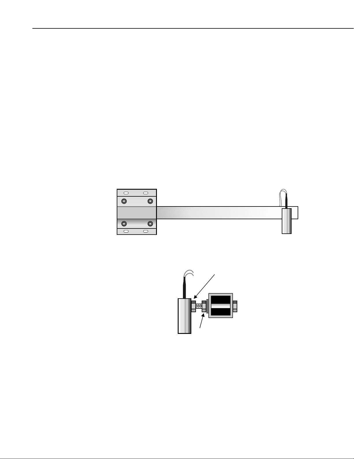
The IRTS-P can be mounted to a Campbell Scientific tripod or tower with the
UT018 Crossarm (Figure 3-1.) A mounting kit (Stainless steel bolt, 2 washers,
and 2 nuts PN 14475) is included with the IRTS-P that can be used to attach
the sensor to the crossarm (Figure 3-2.)
FIGURE 3-1. IRTS-P on UT018 Crossarm
Tighten against sensor to fix
angle of sensor.
Nut with two lock washers
attaching bolt to the arm.
FIGURE 3-2. Mounting IRTS-P to UT018 Crossarm
2
Page 7

4. Wiring
−
=
ATT
IRTS-P Precision Infrared Temperature Sensor
The IRTS-P has two thermocouple outputs. Each output is a pair of red and
yellow wires. The pair labeled “Target” on the jacket near the wires is the
output from the detector. The pair labeled “Body” is a thermocouple
measuring the temperature of the sensor body. Previous versions of the sensor
had a black band on the target cable to mark it. We recommend measuring the
temperatures with differential voltage thermocouple measurements.
Target – Detector Temperature:
Target
Body
Yellow TC + Differential High
Red TC – Differential Low
Bare - Ground
Sensor Body Temperature:
Yellow TC + Differential High
Red TC – Differential Low
Bare - Ground
5. Example Programs
The datalogger program to measure the IRTS-P measures the thermocouple
outputs to obtain the IRTS-P sensor body tem perature a nd t he appa rent
(uncorrected) temperature of the target.
The thermocouple temperature requires the temperature of the terminals to
which the thermocouples are connected. The panel temperature is used as the
reference for the CR23X, CR1000, and CR5000. The module temperature is
not an accurate measurement of the CR10X panel temperature; a CR10XTCR
is required to measure the reference temperature.
After measuring the thermocouple outputs, the sensor body temperature is used
to calculate correction coefficients that are then used to correct the target
temperature.
All three example programs measure the sensor once a second and output
average values once an hour. The actual channels and outputs intervals need to
be adjusted for the actual installation and application.
The equations implemented in the program are (Bugbee
Corrected Target Temperature,
were
and Sensor Error Correction,
= Apparent Target Temperature,
2
KHATTPSEC −−= ;
et.al. 1996)
SECATTCTT
)))((/25.0(
SBSBSB
3
Page 8

IRTS-P Precision Infrared Temperature Sensor
SB
and
00558.059237.09092.49 SBSBP
SB
SB
=SB
Sensor Body Temperature
00077.04248.02828.4 SBSBH
387.03816.50705.52 SBSBK
⋅+⋅−=
⋅+⋅+=
⋅−⋅+=
2
2
2
The three example programs measure the sensor once a second and output
average sensor and target temperatures once an hour. In an actual installation
the measurement and output intervals, and channels used may be changed to
accommodate the other measurements and outputs.
TABLE 5-1. Wiring for Example Programs
Sensor/Lead Description CR10X CR23X CR1000
CR10XTCR
Reference Temp:
Not
Used
Not
Used
Black Excitation E3
Red Signal SE1
Clear Ground AG
IRTS-P – Target/Black Band
Detector Temp
Yellow TC + 2H 1H 1H
Red TC - 2L 1L 1L
IRTS-P – Body/No Band
Sensor Temp
Yellow TC + 3H 2H 2H
Red TC - 3L 2L 2L
Bare wire Shield G
4
CR10X Example Program
;{CR10X}
;
*Table 1 Program
01: 1 Execution Interval (seconds)
;Measure CR10XTCR Reference Temperature
1: Temp (107) (P11)
1: 1 Reps
2: 1 SE Channel
3: 3 Excite all reps w/E3
4: 1 Loc [ RefTemp ]
5: 1.0 Mult
6: 0.0 Offset
;Measure IRt/c apparent target temperature
Page 9

IRTS-P Precision Infrared Temperature Sensor
2: Thermocouple Temp (DIFF) (P14)
1: 1 Reps
2: 21 2.5 mV 60 Hz Rejection Range
3: 2 DIFF Channel
4: 3 Type K (Chromel-Alumel)
5: 1 Ref Temp (Deg. C) Loc [ RefTemp ]
6: 2 Loc [ AppTargT ]
7: 1.0 Mult
8: 0.0 Offset
;Measure Sensor Body Temp
3: Thermocouple Temp (DIFF) (P14)
1: 1 Reps
2: 21 2.5 mV 60 Hz Rejection Range
3: 3 DIFF Channel
4: 3 Type K (Chromel-Alumel)
5: 1 Ref Temp (Deg. C) Loc [ RefTemp ]
6: 3 Loc [ SenBodyT ]
7: 1.0 Mult
8: 0.0 Offset
;Calculate P, H, & K Coefficients
4: Polynomial (P55)
1: 1 Reps
2: 3 X Loc [ SenBodyT ]
3: 4 F(X) Loc [ Psb ]
4: 49.9092 C0
5: 0.59237 C1
6: 0.00558 C2
7: 0.0 C3
8: 0.0 C4
9: 0.0 C5
5: Polynomial (P55)
1: 1 Reps
2: 3 X Loc [ SenBodyT ]
3: 5 F(X) Loc [ Hsb ]
4: 4.2828 C0
5: 0.4248 C1
6: -0.00077 C2
7: 0.0 C3
8: 0.0 C4
9: 0.0 C5
6: Polynomial (P55)
1: 1 Reps
2: 3 X Loc [ SenBodyT ]
3: 6 F(X) Loc [ Ksb ]
4: 52.0705 C0
5: -5.3816 C1
6: 0.387 C2
7: 0.0 C3
8: 0.0 C4
9: 0.0 C5
5
Page 10

IRTS-P Precision Infrared Temperature Sensor
;Calculate correction factor (SEC)
7: Z=1/X (P42) ; {1/Psb}
1: 4 X Loc [ Psb ]
2: 4 Z Loc [ Psb ]
8: Z=X*F (P37) ; {.25/Psb}
1: 4 X Loc [ Psb ]
2: 0.25 F
3: 4 Z Loc [ Psb ]
9: Z=X-Y (P35) ; {ATT - Hsb}
1: 2 X Loc [ AppTargT ]
2: 5 Y Loc [ Hsb ]
3: 5 Z Loc [ Hsb ]
10: Z=X*Y (P36) ; {ATT - Hsb}^2
1: 5 X Loc [ Hsb ]
2: 5 Y Loc [ Hsb ]
3: 5 Z Loc [ Hsb ]
11: Z=X-Y (P35) ; {subtract Ksb}
1: 5 X Loc [ Hsb ]
2: 6 Y Loc [ Ksb ]
3: 6 Z Loc [ Ksb ]
12: Z=X*Y (P36) ; {calculate SEC}
1: 4 X Loc [ Psb ]
2: 6 Y Loc [ Ksb ]
3: 7 Z Loc [ SEC ]
;Calculate corrected target temperature (CTT)
13: Z=X-Y (P35) ;
1: 2 X Loc [ AppTargT ]
2: 7 Y Loc [ SEC ]
3: 8 Z Loc [ CTT ]
14: If time is (P92)
1: 0 Minutes (Seconds --) into a
2: 60 Interval (same units as above)
3: 10 Set Output Flag High (Flag 0)
15: Real Time (P77)
1: 1220 Year,Day,Hour/Minute (midnight = 2400)
16: Average (P71)
1: 3 Reps
2: 1 Loc [ RefTemp ]
17: Average (P71)
1: 1 Reps
2: 8 Loc [ CTT ]
6
Page 11

IRTS-P Precision Infrared Temperature Sensor
*Table 2 Program
02: 0.0000 Execution Interval (seconds)
*Table 3 Subroutines
End Program
-Input Locations1 RefTemp 1 2 1
2 AppTargT 1 2 1
3 SenBodyT 1 3 1
4 Psb 1 3 3
5 Hsb 1 4 3
6 Ksb 1 2 2
7 SEC 1 1 1
8 CTT 1 0 1
CR23X Example Program
;{CR23X}
;
*Table 1 Program
01: 1 Execution Interval (seconds)
;Measure Panel Reference Temperature
1: Panel Temperature (P17)
1: 1 Loc [ RefTemp ]
;Measure IRt/c apparent target temperature
2: Thermocouple Temp (DIFF) (P14)
1: 1 Reps
2: 21 10 mV, 60 Hz Reject, Slow Range
3: 1 DIFF Channel
4: 3 Type K (Chromel-Alumel)
5: 1 Ref Temp (Deg. C) Loc [ RefTemp ]
6: 2 Loc [ AppTargT ]
7: 1.0 Mult
8: 0.0 Offset
;Measure Sensor Body Temp
3: Thermocouple Temp (DIFF) (P14)
1: 1 Reps
2: 21 10 mV, 60 Hz Reject, Slow Range
3: 2 DIFF Channel
4: 3 Type K (Chromel-Alumel)
5: 1 Ref Temp (Deg. C) Loc [ RefTemp ]
6: 3 Loc [ SenBodyT ]
7: 1.0 Mult
8: 0.0 Offset
7
Page 12

IRTS-P Precision Infrared Temperature Sensor
;Calculate P, H, & K Coefficients
4: Polynomial (P55)
1: 1 Reps
2: 3 X Loc [ SenBodyT ]
3: 4 F(X) Loc [ Psb ]
4: 49.9092 C0
5: 0.59237 C1
6: 0.00558 C2
7: 0.0 C3
8: 0.0 C4
9: 0.0 C5
5: Polynomial (P55)
1: 1 Reps
2: 3 X Loc [ SenBodyT ]
3: 5 F(X) Loc [ Hsb ]
4: 4.2828 C0
5: 0.4248 C1
6: -0.00077 C2
7: 0.0 C3
8: 0.0 C4
9: 0.0 C5
6: Polynomial (P55)
1: 1 Reps
2: 3 X Loc [ SenBodyT ]
3: 6 F(X) Loc [ Ksb ]
4: 52.0705 C0
5: -5.3816 C1
6: 0.387 C2
7: 0.0 C3
8: 0.0 C4
9: 0.0 C5
;Calculate correction factor (SEC)
7: Z=1/X (P42) ; {1/Psb}
1: 4 X Loc [ Psb ]
2: 4 Z Loc [ Psb ]
8: Z=X*F (P37) ; {.25/Psb}
1: 4 X Loc [ Psb ]
2: 0.25 F
3: 4 Z Loc [ Psb ]
9: Z=X-Y (P35) ; {ATT - Hsb}
1: 2 X Loc [ AppTargT ]
2: 5 Y Loc [ Hsb ]
3: 5 Z Loc [ Hsb ]
10: Z=X*Y (P36) ; {ATT - Hsb}^2
1: 5 X Loc [ Hsb ]
2: 5 Y Loc [ Hsb ]
3: 5 Z Loc [ Hsb ]
8
Page 13

IRTS-P Precision Infrared Temperature Sensor
11: Z=X-Y (P35) ; {subtract Ksb}
1: 5 X Loc [ Hsb ]
2: 6 Y Loc [ Ksb ]
3: 6 Z Loc [ Ksb ]
12: Z=X*Y (P36) ; {calculate SEC}
1: 4 X Loc [ Psb ]
2: 6 Y Loc [ Ksb ]
3: 7 Z Loc [ SEC ]
;Calculate corrected target temperature (CTT)
13: Z=X-Y (P35) ;
1: 2 X Loc [ AppTargT ]
2: 7 Y Loc [ SEC ]
3: 8 Z Loc [ CTT ]
14: If time is (P92)
1: 0 Minutes (Seconds --) into a
2: 60 Interval (same units as above)
3: 10 Set Output Flag High (Flag 0)
15: Real Time (P77)
1: 1220 Year,Day,Hour/Minute (midnight = 2400)
16: Average (P71)
1: 3 Reps
2: 1 Loc [ RefTemp ]
17: Average (P71)
1: 1 Reps
2: 8 Loc [ CTT ]
*Table 2 Program
02: 0.0000 Execution Interval (seconds)
*Table 3 Subroutines
End Program
-Input Locations1 RefTemp 1 3 1
2 AppTargT 1 2 1
3 SenBodyT 1 3 1
4 Psb 1 3 3
5 Hsb 1 4 3
6 Ksb 1 2 2
7 SEC 1 1 1
8 CTT 1 1 1
9
Page 14

IRTS-P Precision Infrared Temperature Sensor
CR1000 Example Program
'CR1000
Dim SB, Psb, Hsb, Ksb, SenEC
Public PTemp_C, ATT_C, CTT_C
DataTable(IRTS-P,True,-1)
DataInterval(0,60,Min,0)
Average(1,ATT_C,IEEE4,0)
Average(1,CTT_C,IEEE4,0)
EndTable
BeginProg
Scan(1,Sec,1,0)
'Wiring Panel Temperature measurement PTemp_C:
PanelTemp(PTemp_C,_60Hz)
'IRTS-P Precision Infrared Temperature Sensor measurements ATT_C and CTT_C:
'Measure apparent target temperature with IRTS-P.
TCDiff(ATT_C,1,mV2_5C,1,TypeK,PTemp_C,True,0,_60Hz,1,0)
'Measure IRTS-P sensor body temperature.
TCDiff(SB,1,mV2_5C,2,TypeK,PTemp_C,True,0,_60Hz,1,0)
'Calculate Psb, Hsb, & Ksb coefficients.
Psb=49.9092+(0.59237*SB)-(0.00558*SB^2)
Hsb=4.2828+(0.4248*SB)-(0.00077*SB^2)
Ksb=52.0705-(5.3816*SB)+(0.387*SB^2)
'Calculate correction factor.
SenEC=(0.25/Psb)*((ATT_C-Hsb)^2-Ksb)
'Calculate corrected target temperature.
CTT_C=ATT_C-SenEC
CallTable(IRTS-P)
NextScan
EndProg
10
Page 15

IRTS-P Precision Infrared Temperature Sensor
CR5000 Example Program
Public RefT, TargetCorrT, TC(2), SensorCorr, Psb, Hsb, Ksb
Alias TC(1) = TargetApparentT
Alias TC(2) = SensorBodyT
DataTable (AllDat,1,-1)
DataInterval (0,60,Min,10)
Average (1,RefT,FP2,0)
Average (2,TC(),IEEE4,0)
Average (1,TargetCorrT,IEEE4,0)
EndTable
BeginProg
Scan (1,Sec,3,0)
PanelTemp (RefT,250)
TCDiff (TC(),2,mV20C ,1,TypeK,RefT,True ,0,_60Hz,1.0,0)
Psb = 49.9092 + 0.59237 * SensorBodyT - 0.00558 * SensorBodyT^2
Hsb = 4.2828 + 0.4248 * SensorBodyT - 0.00077 * Sensor B ody T^2
Ksb = 52.0705 - 5.3816 * SensorBodyT + 0.387 * SensorB odyT^2
SensorCorr = (0.25/Psb) * ((TargetAppare ntT - Hsb)^2 - Ksb)
TargetCorrT = TargetApparentT - SensorCorr
CallTable Alldat
NextScan
EndProg
6. Maintenance
As with any optical sensor, it is important to keep the lens and view clean.
Otherwise the sensor will be measuring the temperature of the obstruction
instead of the surface of interest.
Clean the lens gently with a moistened cotton swab. Distilled water or alcohol
works well for most dust/dirt. Salt deposits dissolve better in a weak acid
solution (~0.1 molar).
11
Page 16

IRTS-P Precision Infrared Temperature Sensor
This is a blank page.
12
Page 17

This is a blank page.
Page 18

Campbell Scientific Companies
Campbell Scientific, Inc. (CSI)
815 West 1800 North
Logan, Utah 84321
UNITED STATES
www.campbellsci.com
info@campbellsci.com
Campbell Scientific Africa Pty. Ltd. (CSAf)
PO Box 2450
Somerset West 7129
SOUTH AFRICA
www.csafrica.co.za
cleroux@csafrica.co.za
Campbell Scientific Australia Pty. Ltd. (CSA)
PO Box 444
Thuringowa Central
QLD 4812 AUSTRALIA
www.campbellsci.com.au
info@campbellsci.com.au
Campbell Scientific do Brazil Ltda. (CSB)
Rua Luisa Crapsi Orsi, 15 Butantã
CEP: 005543-000 São Paulo SP BRAZIL
www.campbellsci.com.br
suporte@campbellsci.com.br
Campbell Scientific Canada Corp. (CSC)
11564 - 149th Street NW
Edmonton, Alberta T5M 1W7
CANADA
www.campbellsci.ca
dataloggers@campbellsci.ca
Campbell Scientific Ltd. (CSL)
Campbell Park
80 Hathern Road
Shepshed, Loughborough LE12 9GX
UNITED KINGDOM
www.campbellsci.co.uk
sales@campbellsci.co.uk
Campbell Scientific Ltd. (France)
Miniparc du Verger - Bat. H
1, rue de Terre Neuve - Les Ulis
91967 COURTABOEUF CEDEX
FRANCE
www.campbellsci.fr
campbell.scientific@wanadoo.fr
Campbell Scientific Spain, S. L.
Psg. Font 14, local 8
08013 Barcelona
SPAIN
www.campbellsci.es
info@campbellsci.es
Please visit www.campbellsci.com to obtain contact information for your local US or International representative.
 Loading...