

Page 1

IRS21 Lufft Intelligent
Road Surface Sensor
Revision: 2/09
Copyright © 2005-2009
Campbell Scientific, Inc.
Page 2

Warranty and Assistance
The IRS21 LUFFT INTELLIGENT ROAD SURFACE SENSOR is
warranted by CAMPBELL SCIENTIFIC, INC. to be free from defects in
materials and workmanship under normal use and service for twelve (12)
months from date of shipment unless specified otherwise. Batteries have no
warranty. CAMPBELL SCIENTIFIC, INC.'s obligation under this warranty is
limited to repairing or replacing (at CAMPBELL SCIENTIFIC, INC.'s option)
defective products. The customer shall assume all costs of removing,
reinstalling, and shipping defective products to CAMPBELL SCIENTIFIC,
INC. CAMPBELL SCIENTIFIC, INC. will return such products by surface
carrier prepaid. This warranty shall not apply to any CAMPBELL
SCIENTIFIC, INC. products which have been subjected to modification,
misuse, neglect, accidents of nature, or shipping damage. This warranty is in
lieu of all other warranties, expressed or implied, including warranties of
merchantability or fitness for a particular purpose. CAMPBELL SCIENTIFIC,
INC. is not liable for special, indirect, incidental, or consequential damages.
Products may not be returned without prior authorization. The following
contact information is for US and International customers residing in countries
served by Campbell Scientific, Inc. directly. Affiliate companies handle
repairs for customers within their territories. Please visit
www.campbellsci.com to determine which Campbell Scientific company
serves your country. To obtain a Returned Materials Authorization (RMA),
contact CAMPBELL SCIENTIFIC, INC., phone (435) 753-2342. After an
applications engineer determines the nature of the problem, an RMA number
will be issued. Please write this number clearly on the outside of the shipping
container. CAMPBELL SCIENTIFIC's shipping address is:
CAMPBELL SCIENTIFIC, INC.
RMA#_____
815 West 1800 North
Logan, Utah 84321-1784
CAMPBELL SCIENTIFIC, INC. does not accept collect calls.
Page 3

IRS21 Table of Contents
PDF viewers note: These page numbers refer to the printed version of this document. Use
the Adobe Acrobat® bookmarks tab for links to specific sections.
1. Function........................................................................1
2. Specifications ..............................................................2
3. Installation.................................................................... 4
4. Connections...............................................................16
5. Operation....................................................................17
6. Programming .............................................................18
6.1 CR1000 Program....................................................................................18
6.2 CR10X Program.....................................................................................20
Figures
1-1. IRS21.......................................................................................................1
3-1. Core cut for the road sensor ....................................................................4
3-2. Core drill and saw cutting equipment......................................................5
3-3. Saw cut is masked to control the epoxies................................................6
3-4. View of fast steel.....................................................................................7
3-5. Weights are placed onto the leveling fixtures for the road sensor...........8
3-6. First pour of Fabick epoxy......................................................................9
3-7. Finished pour, with weights removed ...................................................10
3-8. Second pour to bring the epoxy to grade...............................................11
3-9. Backer rod is used as a dam to control the epoxy .................................12
3-10. Compressed air is used to dry and clean the saw cut...........................13
3-11. Application of the sensor cable epoxy ................................................14
3-12. Finished epoxy application..................................................................15
3-13. A junction box is used when cable splices are needed to extend
the cable length .........................................................................................16
i
Page 4

This is a blank page.
Page 5
IRS21 Lufft Intelligent Road Surface Sensor
1. Function
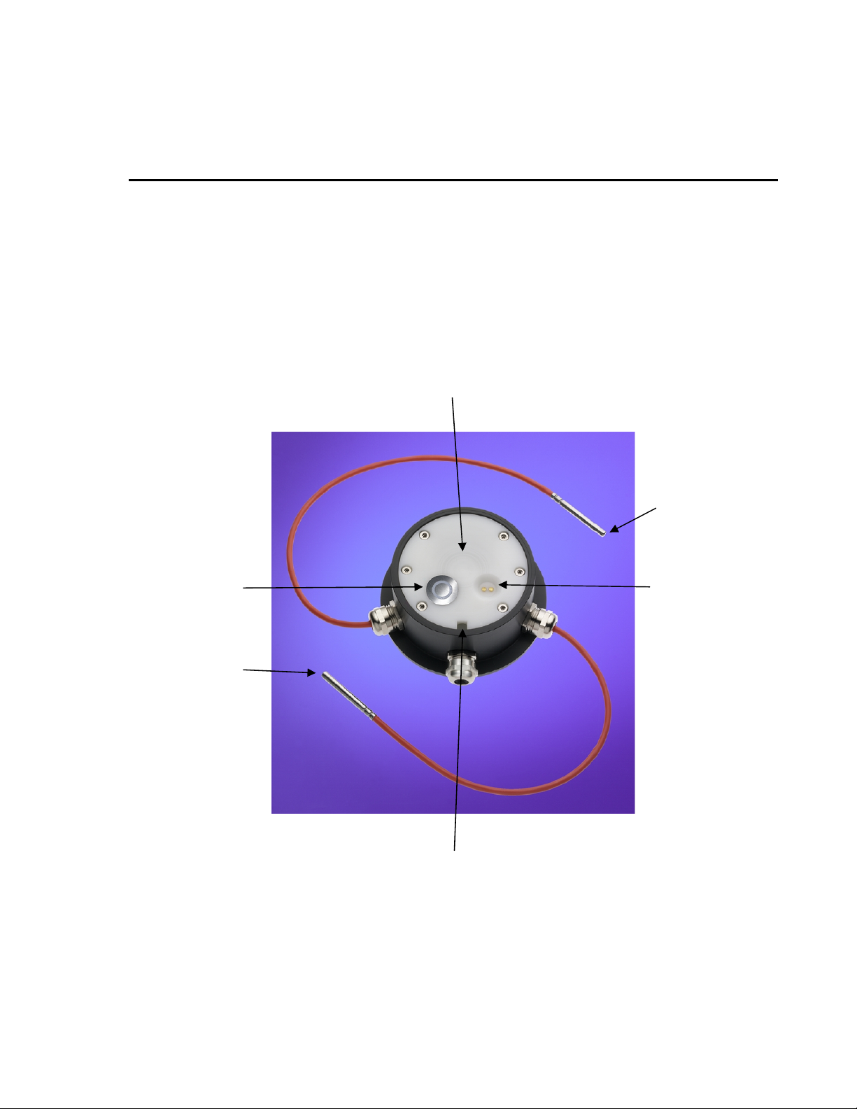
The IRS21 is a sensor that makes measurements of road surface. From
measurements taken, the outputs are up to three temperatures, conductivity,
percent salt, freezing temperature, road condition, and water film height. There
is also an error status output from the sensor. The sensor is used for road
weather stations.
Multiple frequency measurement,
measuring water film height,
snow, and ice
Sub-surface temp. 1
(not installed)
Measuring wet/dry
(conductivity)
Sub-surface temp. 2
(not installed)
Measuring the road surface temperature
FIGURE 1-1. IRS21
Measuring salt
concentration to
calculate the freezing
temperature
1
Page 6

IRS21 Lufft Intelligent Road Surface Sensor
2. Specifications
Dimensions: 5” in diameter, and 2” high
Weight: 2 pounds
Survival temperature: -57° to 158°F (-50° to 70°C)
Rated current: less than 200 ma
Interface: RS485
Standard cable length: 75 feet (25m)
Optional cable length: up to 300’ (100M)
Power supply: 9 to 14 Vdc
Operating temperature: -40° to 158°F (-40° to 70°C)
Operating relative humidity: 100%
Outputs
Road condition: dry, damp, wet, snow, freezing wetness, ice
Road temperature: -40° to 158°F (-40° to 70°C)
Accuracy ±0.2°C (-10° to 10°C);
±0.5°C (-40° to 70°C)
Resolution -.1°C
Freezing point: -4° to 32°F (-20° to 0°C)
Accuracy ±.1°C
Resolution -.1°C
Needed Accessories
RS485 to RS-232 adapter Lufft pn 8410.KON – Campbell part number 18080
SDM-SIO4
Warranty Exclusions
Due to important installation considerations, the following sensors will not be
warranted.
1. Sensors that aren’t installed flush with the road surface.
If the road sensor is installed above the road surface, damage to the sensor
could result from equipment contacting the sensor.
If the sensor is mounted below the road surface, incorrect measurements
are possible due to the pooling effect of material on top of the sensor that
is not representative of the road surface.
2
2. Sensors with exposed sensor cable in the road surface.
Page 7

IRS21 Lufft Intelligent Road Surface Sensor
Equipment Needed for Installation
1. Drill and 5” core bit for the sensor hole.
2. Cement/concrete saw for the sensor lead saw cut with 1/2” saw blade.
3. Trencher for the sensor lead in the road shoulder.
4. Air nozzle to clean the cuts.
5. Hammer drill and 1/2” by 24” drill bit for the temperature sensors.
6. 115 VAC generator, 5 kW.
7. Portable compressor, 9 CFW.
Supplies Needed for Installation
1. Backer rod.
2. Epoxy.
3. PVC pipe for the sensor lead in the road shoulder. This isn’t required but
adds protection for the cable.
4. Chalk line.
5. Duct tape.
6. Hammer and chisel.
3
Page 8
IRS21 Lufft Intelligent Road Surface Sensor
3. Installation
4
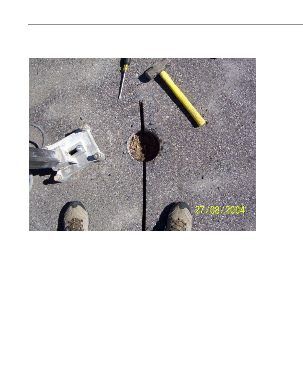
FIGURE 3-1. Core cut for the road sensor.
Hole diameter = 6”
Hole depth = 3”
Saw cut depth = 2”
Saw cut width = 1/2”
Locate the place in the pavement for the sensor. Drill the sensor hole 3” deep,
and clear the drilled hole of all excess material.
Saw cut the road surface for the sensor lead. The cut needs to be extended
beyond the sensor hole to completely clear the sensor hole of excess material.
Page 9
IRS21 Lufft Intelligent Road Surface Sensor
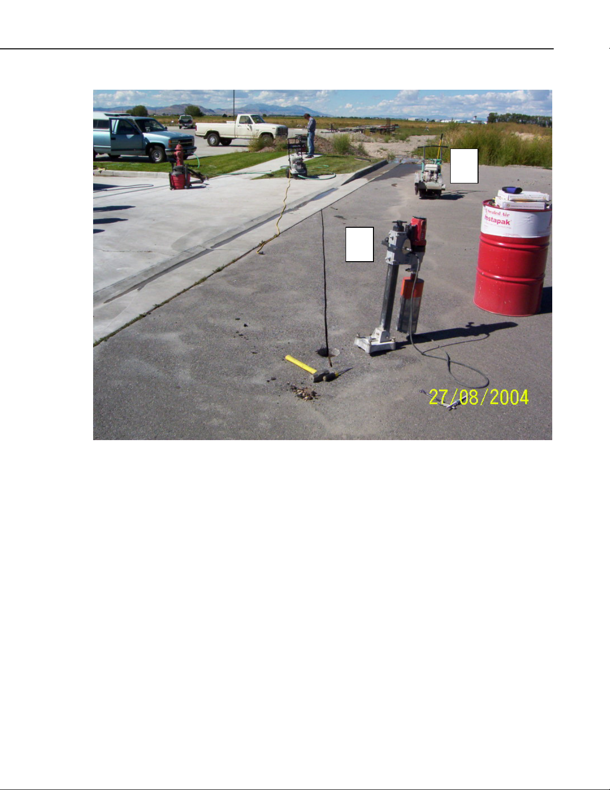
B
A
FIGURE 3-2. Core drill (A) and saw cutting (B) equipment.
5
Page 10
IRS21 Lufft Intelligent Road Surface Sensor
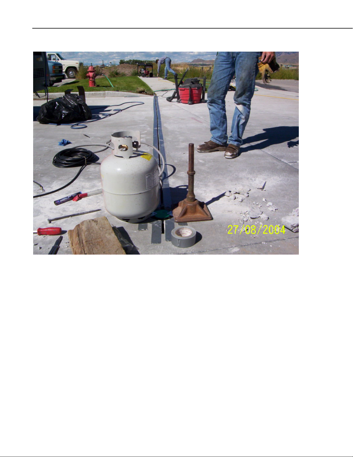
FIGURE 3-3. Saw cut is masked with duct tape to control the epoxies.
6
Page 11

IRS21 Lufft Intelligent Road Surface Sensor
FIGURE 3-4. View of fast steel which is placed under the sensor
prior to epoxy application to provide a base for the sensor.
1 ” b all
Fast Steel
The fast steel is used to control the depth that the sensor fits into the sensor
hole, and the limiting fixtures on the sensor make the sensor even with the road
surface.
7
Page 12

IRS21 Lufft Intelligent Road Surface Sensor
FIGURE 3-5. Weights are placed onto the leveling fixtures for the road sensor.
One weight is placed on each leveling fixture.
8
Page 13

IRS21 Lufft Intelligent Road Surface Sensor
FIGURE 3-6. First pour of Fabick epoxy, pn FJS (fast set), useable between 20
An Excel worksheet is available on our web site to calculate the amount of
epoxy needed. The file is located at www.campbellsci.com/downloads
first pour of the epoxy fills and assures that there is complete coverage around
the sensor and sensor cable. The second pour fills to the road surface.
°
to 180°F.
. The
9
Page 14

IRS21 Lufft Intelligent Road Surface Sensor
FIGURE 3-7. Finished pour, with weights removed.
Above is the finished epoxy around the sensor. There is a dam of backer rod
that prevents epoxy from draining from around the sensor while filling the
sensor hole.
A dam of backer rod also can be used for the sensor cable fill. If there is any
banking on the road, this is an effective way to fill the saw cut and the sensor
hole to the required height.
10
Page 15

IRS21 Lufft Intelligent Road Surface Sensor
FIGURE 3-8. Second pour to bring the epoxy to grade.
After the first pour has hardened, the fixtures on sensor for making the sensor
even with the road surface can be removed before adding more epoxy.
11
Page 16

IRS21 Lufft Intelligent Road Surface Sensor
FIGURE 3-9. Backer rod is used as a dam to control the epoxy.
Different epoxies can be used for directly around the sensor and along the cable.
Since the epoxy used is liquid, the backer rod is used to dam the epoxy until cured.
12
Page 17

IRS21 Lufft Intelligent Road Surface Sensor
FIGURE 3-10. Compressed air is used to dry and clean the saw cut.
13
Page 18

IRS21 Lufft Intelligent Road Surface Sensor
FIGURE 3-11. Application of the sensor cable epoxy.
The saw cut is two inches deep. The backer rod is placed in the length of the saw cut below and above
the sensor cable before epoxy application.
Backer Rod
5/8” diameter
2”
Sensor Cables
3/8” diameter
(IRS21 and
107s if used)
The backer rod in the saw cut should have a friction fit. When the epoxy fills
the saw cut, if there is no friction fit, the backer rod tends to float to the road
surface.
½”
14
Page 19

IRS21 Lufft Intelligent Road Surface Sensor
FIGURE 3-12. Finished epoxy application.
15
Page 20

IRS21 Lufft Intelligent Road Surface Sensor
FIGURE 3-13. A junction box is used when cable splices are needed to extend the cable length.
4. Connections
Sensor Interface
White — GND
Brown — 12 VDC
Green — RS485B
Yellow — RS485A
Junction
Box
@GD
@UB
@B GND
@A UB
RS-232
GND
12 VDC
Enclosure
SDM-SIO4
16
Page 21

IRS21 Lufft Intelligent Road Surface Sensor
U
Input
connector
B
RS232
connector
Output
connector
GND
Sensor Co nnector
DIP Switch
X
X
The interface has a two position dip switch that can change the interface from
master to slave operation. For operation with the RWIS station the interface is
set to master and each interface takes a port on the SDM-SIO4.
The switches in the two left hand positions as indicated by the X’s above make
the interface a master.
The sensors can be daisy chained. This is done by writing the address of the
sensor with software available only to the manufacturer at this time. The
sensor connections are made to the sensor connector.
5. Operation
The input connector and output connectors are used for daisy chain operation,
but are also used to supply the 12 volts to the interface and sensor.
In the figure above, power is applied to the input and output connectors.
12 volts is connected to the UB connection of the input connector from the
power buss. Ground is connected from the power buss to the GND connection
to the output connector.
The sensor is operated at two-minute intervals. This is done to prevent
measurement errors from sensor heating that could happen if the sensor were
powered too long. The sensor is polled with a command that asks for:
Temperature 1
Temperature 2
Temperature 3
Salt concentration
Freezing temperature
Water film height
Road condition
Error status
Sensors purchased for the Campbell Scientific RWIS station are not optioned
with the first two temperature sensors. For these applications, 107 probes are
used for sub surface temperature measurements. When these are used, one is
placed at the bottom of the saw cut near the sensor. The other 107 is placed
into the bottom of an 18” deep by 1/2” hole under the 107 probe placed into the
saw cut near the IRS21.
17
Page 22

IRS21 Lufft Intelligent Road Surface Sensor
The data returned consists of the polling command and ASCII data. Spaces
separate the data points.
In typical operation the sensor is run in table two in mixed array loggers, and
slow sequence in PakBus loggers. The interval for the sensor is two minutes.
6. Programming
The sensor is first powered with the DTR line set high. Then the RTS is set
low to send data to the sensor. In this case the polling command will be sent to
the sensor. As soon as the polling command is sent, RTS is set high to get data
back from the sensor. In as short a time as is possible by the programming.
RTS is set high to receive the data. Then the receive filter is sent to the SDMSIO4, and data is retrieved by the logger.
In both programs below the SDM-SIO4 is set up with code at the start of the
program. This ensures that if there is a reset or power is lost, the startup will
configure the SDM-SIO4 without having to connect to the SDM-SIO4 to
configure the device.
The calculations after reading the SDM-SIO4 are used to convert raw data
measurements from the sensor to measurements such as degrees, and film
thickness.
6.1 CR1000 Program
Although this example program is for the CR1000, other CRBasic dataloggers
are programmed similarly.
'CR1000 Series Datalogger
'To create a different opening program template, type in new
'instructions and select Template | Save as Default Template
'date:
'program author:
'Declare Public Variables
'Example:
Public sio4result,counter,a
Public sensordata(8)
dim reqdata(17)
dim datafilter(18)
dim portset(22)
alias sensordata(1)=temperature1
alias sensordata(2)=temperature2
alias sensordata(3)=SurTmp0
alias sensordata(4)=SurSal0
alias sensordata(5)=SurFrePn0
alias sensordata(6)=SurWatDp0
alias sensordata(7)=SurSta0
alias sensordata(8)=PavSenEr0
18
Page 23

IRS21 Lufft Intelligent Road Surface Sensor
'Declare Other Variables
'Example:
'Dim Counter
'Declare Constants
'Example:
'CONST PI = 3.141592654
DataTable (road,True,10)
Sample (1,temperature1,FP2)
Sample (1,temperature2,FP2)
Sample (1,SurTmp0,FP2)
Sample (1,SurSal0,FP2)
Sample (1,SurFrePn0,FP2)
Sample (1,SurWatDp0,FP2)
Sample (1,SurSta0,FP2)
Sample (1,PavSenEr0,FP2)
EndTable
'Define Subroutines
'Sub
Sub sio4setup
'request data string &&A^M^J #1
data 115,116,114,115,116,32,49,32,34,38,38,65,94,77,94,74,34
for a=1 to 17 : read reqdata(a) : next a
SDMSIO4 (reqdata(),1,0,4,321,0000,0000,17,1.0,0)
Delay (1,2,Sec)
'data fillter string ffffffff #2
data 102,108,116,115,116,32,50,32,34,102,102,102,102,102,102,102,102,34
for a=1 to 18 : read datafilter(a) : next a
SDMSIO4 (datafilter(),1,0,4,321,0000,0000,18,1.0,0)
Delay (1,2,Sec)
'port setup for port 4 4 13 3 0 0 9 0
data 112,111,114,116,115,101,116,32,52,32,49,51,32,51,32,48,32,48,32,57,32,48
for a=1 to 22 : read portset(a) : next a
SDMSIO4 (portset(),1,0,4,321,0000,0000,22,1.0,0)
Delay (1,2,Sec)
EndSub
'Main Program
BeginProg
'Enter other measurement instructions
'Call Output Tables
'Example:
SlowSequence
Scan (120,Sec,3,0) 'irs21
19
Page 24

IRS21 Lufft Intelligent Road Surface Sensor
'rts hi to send polling string, dtr hi to power the road sensor
SDMSIO4 (sio4result,1,0,4,1027,0022,0000,0,1.0,0)
Delay (1,1,Sec)
SDMSIO4 (sio4result,1,0,4,1027,0010,0,0,1.0,0)
'rts lo to send data to the sensor
SDMSIO4 (sio4result,1,0,4,1024,0001,0000,0,1.0,0)
Delay (1,1,mSec)
'rts hi to receive data from the sensor
SDMSIO4 (sio4result,1,0,4,1027,0020,0000,0,1.0,0)
Delay (1,1,Sec)
'dtr lo to turn the sensor off
SDMSIO4 (sio4result,1,0,4,1027,0001,0000,0,1.0,0)
Delay (1,1,Sec)
'send the filter
SDMSIO4 (datafilter(),1,0,4,2054,9002,0000,18,1.0,0)
'read the sio4
SDMSIO4 (sensordata(),1,0,4,4,0000,0000,8,1.0,0)
Delay (1,1,Sec)
SurTmp0=(SurTmp0*.1)-50
SurSal0=(SurSal0*.1)
SurFrePn0=(SurFrePn0*.1)*-1
SurWatDp0=((1560)-(16.55*SurWatDp0)+(.041*SurWatDp0^2))/1000
CallTable road
NextScan
EndProg
6.2 CR10X Program
;{CR10X-TD}
;
*Table 1 Program
01: 60 Execution Interval (seconds)
;nosensor initialization
1: If (X<=>F) (P89)
1: 93 X Loc [ inp_init ]
2: 1 =
3: 0 F
4: 1 Call Subroutine 1
2: Z=F x 10^n (P30)
1: 1 F
2: 0 n, Exponent of 10
3: 93 Z Loc [ inp_init ]
*Table 2 Program
02: 120 Execution Interval (seconds)
20
Page 25

IRS21 Lufft Intelligent Road Surface Sensor
;start irs21 sensor 1
;the polling string to send to the sensor for measurement is strst 1 "&26&41&0D&0A"
;the filter string for the sio4 is fltst 12 "n9Fn1Fn1fn3Fn1Fn3fff"
;the port setup is portset 3 13 3 0 0 9 0
;this sensor is set up for 19.2 kbaud, no parity, 8 data bits, 1 stop bit
;dtr hi to power the interface and puck and rts high for data to logger
1: SDM-SIO4 (P113)
1: 1 Reps
2: 0 Address
3: 3 Send/Receive Port 3
4: 1027 Command
5: 0022 1st Parameters
6: 0000 2nd Parameters
7: 0 Values per Rep
8: 1 Loc [ dummy ]
9: 1.0 Mult
10: 0.0 Offset
2: Delay w/Opt Excitation (P22)
1: 1 Ex Channel
2: 0 Delay W/Ex (0.01 sec units)
3: 250 Delay After Ex (0.01 sec units)
4: 0 mV Excitation
;rts lo to send data to sensor
3: SDM-SIO4 (P113)
1: 1 Reps
2: 0 Address
3: 3 Send/Receive Port 3
4: 1027 Command
5: 0010 1st Parameters
6: 0000 2nd Parameters
7: 0000 Values per Rep
8: 1 Loc [ dummy ]
9: 1.0 Mult
10: 0.0 Offset
;&A<cr> to sensor
4: SDM-SIO4 (P113)
1: 1 Reps
2: 0 Address
3: 3 Send/Receive Port 3
4: 1024 Command
5: 0001 1st Parameters
6: 0000 2nd Parameters
7: 0 Values per Rep
8: 1 Loc [ dummy ]
9: 1.0 Mult
10: 0.0 Offset
21
Page 26

IRS21 Lufft Intelligent Road Surface Sensor
5: Delay w/Opt Excitation (P22)
1: 1 Ex Channel
2: 0 Delay W/Ex (0.01 sec units)
3: 1 Delay After Ex (0.01 sec units)
4: 0 mV Excitation
;rts hi to receive data from the sensor
6: SDM-SIO4 (P113)
1: 1 Reps
2: 0 Address
3: 3 Send/Receive Port 3
4: 1027 Command
5: 0020 1st Parameters
6: 0000 2nd Parameters
7: 0000 Values per Rep
8: 1 Loc [ dummy ]
9: 1.0 Mult
10: 0.0 Offset
7: Delay w/Opt Excitation (P22)
1: 1 Ex Channel
2: 0 Delay W/Ex (0.01 sec units)
3: 50 Delay After Ex (0.01 sec units)
4: 0 mV Excitation
;dtr low to turn the interface and sensor off
8: SDM-SIO4 (P113)
1: 1 Reps
2: 0 Address
3: 3 Send/Receive Port 3
4: 1027 Command
5: 0001 1st Parameters
6: 0 2nd Parameters
7: 0 Values per Rep
8: 1 Loc [ dummy ]
9: 1.0 Mult
10: 0.0 Offset
;send filter to sio4
9: SDM-SIO4 (P113)
1: 1 Reps
2: 0 Address
3: 3 Send/Receive Port 3
4: 2054 Command
5: 9012 1st Parameters
6: 0000 2nd Parameters
7: 0000 Values per Rep
8: 1 Loc [ dummy ]
9: 1.0 Mult
10: 0.0 Offset
22
Page 27

IRS21 Lufft Intelligent Road Surface Sensor
10: Delay w/Opt Excitation (P22)
1: 1 Ex Channel
2: 0 Delay W/Ex (0.01 sec units)
3: 1 Delay After Ex (0.01 sec units)
4: 0 mV Excitation
;read the sio4
11: SDM-SIO4 (P113)
1: 1 Reps
2: 0 Address
3: 3 Send/Receive Port 3
4: 4 Command
5: 0000 1st Parameters
6: 0000 2nd Parameters
7: 8 Values per Rep
8: 2 Loc [ pavt1_1 ]
9: 1.0 Mult
10: 0.0 Offset
intemp=(pavt1_3*.1)-50
salt=pavt1_4*.1
freztemp=pavt1_5*.1
waterflm=(1560-(16.55*pavt1_6)+(.041*pavt1_6*pavt1_6))/1000
*Table 3 Subroutines
;start of sdm-sio4 setup
1: Beginning of Subroutine (P85)
1 1 Subroutine 1
;data filter
2: Bulk Load (P65)
1: 102 F ;f
2: 108 F ;l
3: 116 F ;t
4: 115 F ;s
5: 116 F ;t
6: 32 F ;space
7: 49 F ;1
8: 50 F ;2
9: 10 Loc [ flt1_1 ]
3: Bulk Load (P65)
1: 32 F ;space
2: 34 F ;"
3: 110 F ;n
4: 57 F ;9
5: 70 F ;F
6: 110 F ;n
7: 49 F ;1
8: 70 F ;F
9: 18 Loc [ flt9_1 ]
23
Page 28

IRS21 Lufft Intelligent Road Surface Sensor
4: Bulk Load (P65)
1: 110 F ;n
2: 49 F ;1
3: 102 F ;f
4: 110 F ;n
5: 51 F ;3
6: 70 F ;F
7: 110 F ;n
8: 49 F ;1
9: 26 Loc [ flt17_1 ]
5: Bulk Load (P65)
1: 70 F ;F
2: 110 F ;n
3: 51 F ;3
4: 102 F ;f
5: 102 F ;f
6: 102 F ;f
7: 34 F ;"
8: 0 F ;
9: 34 Loc [ flt25_1 ]
;request data string
6: Bulk Load (P65)
1: 115 F ;s
2: 116 F ;t
3: 114 F ;r
4: 115 F ;s
5: 116 F ;t
6: 32 F ;space
7: 49 F ;1
8: 32 F ;space
9: 42 Loc [ st1_1 ]
7: Bulk Load (P65)
1: 34 F ;"
2: 38 F ;&
3: 50 F ;2
4: 54 F ;6
5: 38 F ;&
6: 52 F ;4
7: 49 F ;1
8: 38 F ;&
9: 50 Loc [ st9_1 ]
8: Bulk Load (P65)
1: 48 F ;0
2: 68 F ;D
3: 38 F ;&
4: 48 F ;0
5: 65 F ;A
6: 34 F ;"
7: 0 F
8: 0 F
9: 58 Loc [ st17_1 ]
24
Page 29

;sdm-s014 portset
9: Bulk Load (P65)
1: 112 F ;p
2: 111 F ;o
3: 114 F ;r
4: 116 F ;t
5: 115 F ;s
6: 101 F ;e
7: 116 F ;t
8: 32 F ;space
9: 66 Loc [ port1_1 ]
10: Bulk Load (P65)
1: 51 F ;3
2: 32 F ;space
3: 49 F ;1
4: 51 F ;3
5: 32 F ;space
6: 51 F ;3
7: 32 F ;space
8: 48 F ;0
9: 74 Loc [ port9_1 ]
11: Bulk Load (P65)
1: 32 F ;space
2: 48 F ;0
3: 32 F ;space
4: 57 F ;9
5: 32 F ;space
6: 48 F ;0
7: 0 F
8: 0 F
9: 82 Loc [ port17_1 ]
;portset
12: SDM-SIO4 (P113)
1: 1 Reps
2: 0 Address
3: 5 Send to all four ports
4: 321 Command
5: 0 1st Parameters
6: 0 2nd Parameters
7: 22 Values per Rep
8: 66 Loc [ port1_1 ]
9: 1.0 Multiplier
10: 0.0 Offset
;data filter
IRS21 Lufft Intelligent Road Surface Sensor
25
Page 30

IRS21 Lufft Intelligent Road Surface Sensor
13: SDM-SIO4 (P113)
1: 1 Reps
2: 0 Address
3: 1 Send/Receive Port 1
4: 321 Command
5: 0 1st Parameters
6: 0 2nd Parameters
7: 31 Values per Rep
8: 10 Loc [ flt1_1 ]
9: 1.0 Multiplier
10: 0.0 Offset
;request data
14: SDM-SIO4 (P113)
1: 1 Reps
2: 0 Address
3: 1 Send/Receive Port 1
4: 321 Command
5: 0 1st Parameters
6: 0 2nd Parameters
7: 22 Values per Rep
8: 42 Loc [ st1_1 ]
9: 1.0 Multiplier
10: 0.0 Offset
15: End (P95)
End Program
26
Page 31

This is a blank page.
Page 32

Campbell Scientific Companies
Campbell Scientific, Inc. (CSI)
815 West 1800 North
Logan, Utah 84321
UNITED STATES
www.campbellsci.com
info@campbellsci.com
Campbell Scientific Africa Pty. Ltd. (CSAf)
PO Box 2450
Somerset West 7129
SOUTH AFRICA
www.csafrica.co.za
cleroux@csafrica.co.za
Campbell Scientific Australi
PO Box 444
Thuringowa Central
QLD 4812 AUSTRALIA
www.campbellsci.com.au
info@campbellsci.com.au
Campbell Scientific do Brazil Ltda. (CSB)
Rua Luisa Crapsi Orsi, 15 Butantã
CEP: 005543-000 São Paulo SP BRAZIL
www.campbellsci.com.br
suporte@campbellsci.com.br
Campbell Scientific Canada Corp. (CSC)
11564 - 149th Street NW
Edmonton, Alberta T5M 1W7
CANADA
www.campbellsci.ca
dataloggers@campbellsci.ca
Campbell Scientific Ltd. (CSL)
Campbell Park
80 Hathern Road
Shepshed, Loughborough LE12 9GX
UNITED KINGDOM
www.campbellsci.co.uk
sales@campbellsci.co.uk
Campbell Scientific Ltd. (France)
Miniparc du Verger - Bat. H
1, rue de Terre Neuve - Les Ulis
91967 COURTABOEUF CEDEX
FRANCE
www.campbellsci.fr
info@campbellsci.fr
Campbell Scientific Spain, S. L.
Psg. Font 14, local 8
08013 Barcelona
SPAIN
www.campbellsci.es
info@campbellsci.es
Please visit www.campbellsci.com to obtain contact information for your local US or International representative.
a Pty. Ltd. (CSA)
 Loading...