

Page 1
Hydro-Wiper
Operation Manual
Hydro-Wiper # C for OBS3+ sensor
External trigger controlled version
Page 2

Hydro-Wiper operation manual
Overview
The Hydro-Wiper is a mechanical wiper system designed to be easily
fitted to the D&A OBS 3+.
By wiping at regular intervals, the Hydro-Wiper keeps the optical
window of the OBS3+ clear of bio-fouling and other deposits such as
mud. This reduces the necessity for costly site visits to manually
clean the sensor, and maintains data quality throughout the
deployment.
The Hydro-Wiper consists of a wiper body that the OBS3+ is
clamped onto. The wiper body is connected to a wiper control
module by a cable. The wiper control module has a trigger input,
which is connected to the control line of a data-logger. When the
control line is driven high (+5 volt) by the data logger, the HydroWiper performs a wipe.
The wiper drive shaft features a slip mechanism which prevents
damage to the wiper motor gearbox if the wiper arm is knocked or
jolted during the deployment.
The wiper control module incorporates a micro-processor, which
intelligently manages the wipe operation. The wiper control module
also monitors the position of the wiper arm between wipes. If the
wiper arm is knocked or jolted so that it is in the region in front of the
OBS3+, then the Hydro-Wiper will detect this and move the wiper
arm to one side.
The Hydro-Wiper has been carefully designed for minimal power
consumption, making it suitable for remote field sites, where power
availability maybe limited.
Zebra-Tech Ltd
1
Page 3
Hydro-Wiper operation manual
Installation
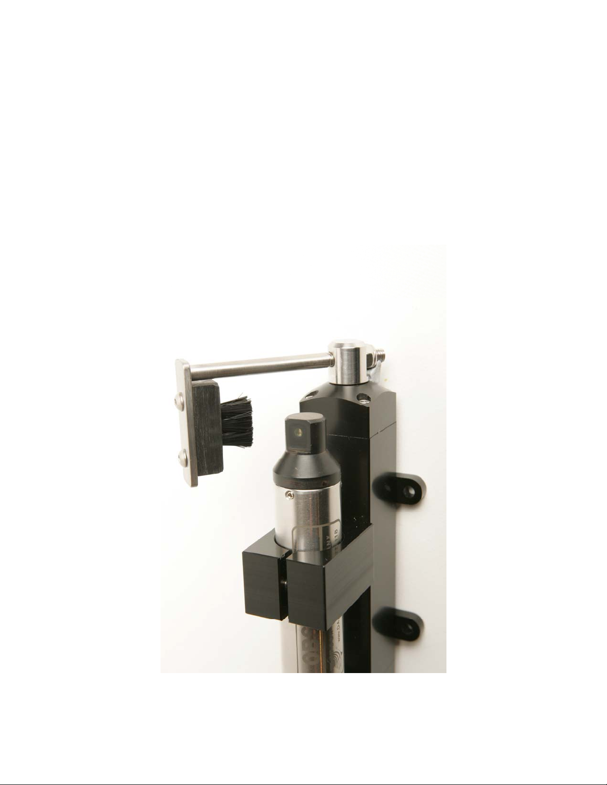
The OBS3+ is mounted in the clamp at the front of the wiper, with the
optical window facing directly away from the Hydro-Wiper. The
OBS3+ should be positioned so that the brush sweeps across the
whole surface of the optical window (Photo 1).
Photo 1. Mounting the OBS3+ in the Hydro-Wiper clamp
Zebra-Tech Ltd
2
Page 4

Hydro-Wiper operation manual
While setting up the Hydro-Wiper, the brush arm can be manually
moved to check the OBS3+ is correctly positioned. Ensure that the
Hydro-Wiper is not powered up prior to doing this.
The brush is mounted on an adjustable arm. The length of the arm
controls the brush pressure applied to the face of the OBS3+. This
has been factory set, and should not need adjustment.
If it is necessary to adjust the brush pressure, this can be done by
loosening the lock nut at the end of the wiper arm and rotating the
wiper arm in the desired direction. The lock nut should be tightened
after adjustment.
If there is excessive brush pressure, the life of the brush will be
reduced and damage to the optical surface of the OBS3+ may occur.
If the brush pressure is insufficient, contact between the brush and
optical window will be lost in the centre of the window and fouling
may occur.
The cable between the wiper housing and wiper control module
should be fully secured in position. If it is free to constantly move in
the water currents, damage from fatigue and eventual failure may
result.
Zebra-Tech Ltd
Photo 2. Wiper control module
3
Page 5

Hydro-Wiper operation manual
The wiper control module is not water proof, and should be mounted
inside a weather-proof housing, ideally adjacent to the controlling
data logger.
The ground (GND) connection of the wiper control module must be
connected to both the +12 volt supply ground, and the data logger
control ground.
The power supply to the Hydro-Wiper must be between 8 and 15
volts DC, and capable of supplying around 90mA during a wipe, and
momentarily up to 500mA if the wiper arm becomes jammed.
The control connection of the wiper control module is connected to
the data logger control port. The control port needs driven to +5 volts
for longer than 10 milliseconds to trigger a wipe.
The wiper control module is fitted with plug-in screw terminals. This
simplifies passing the cable through a gland in the data logger
cabinet.
Zebra-Tech Ltd
4
Page 6

Hydro-Wiper operation manual
Operation
Warning
When power to the Hydro-Wiper is switched on, the wiper arm will
immediately start moving.
On power up, if the wiper arm is not at the start position, then the
wiper arm will first rotate to the start position. From the start position,
the brush will wipe across the face of the OBS3+, and then move
back to the start position, thus brushing the OBS3+ face in two
directions.
The Hydro-Wiper will then wait until a control trigger is received from
the data logger before a wipe is performed. The Hydro-Wiper power
consumption between wipes is very low; around 0.05mA.
The Hydro-Wiper regularly monitors the position of the wiper arm
between wipes. If it gets knocked or jolted into the region in front of
the OBS3+, this is detected, and the wiper arm is moved to one side.
When the control line of the wiper control module is driven high (+5
volts) by the data logger, a wipe is initiated. The brush sweeps
across the face of the OBS3+, stops, and then sweeps back in the
opposite direction to the starting position. A wipe typically takes
around 10 seconds to complete.
After the control line has gone high, it will need to go low (0 volt) prior
to going high to initiate another wipe. If the control line stays high,
another wipe will not occur until the control line goes low, then high
again.
The optimal frequency of wiping the OBS3+ depends on the rate of
fouling. Under typical conditions, a wipe interval of 2 to 4 hours
should be adequate to prevent fouling; however this may be
increased or decreased, depending on the characteristics of the site.
Zebra-Tech Ltd
5
Page 7

Hydro-Wiper operation manual
The timing of the wipe is optimally just prior to making a
measurement with the OBS3+. It is recommended that a small time
interval occurs between the wipe and the measurement, to allow for
settling of debris dislodged during the wipe.
If the wiper arm becomes jammed at any stage during a wipe, the
direction of rotation will be reversed in an attempt to dislodge the
obstruction. If this is un-successful after a number of attempts, then
the Hydro-Wiper will abort the wipe. As a result, the Hydro-Wiper is
not damaged by a jammed wiper arm.
The wiper control module features an LED. On power-up, the LED
will flash once. The LED will then flash once every 10 seconds. If the
wiper arm becomes jammed, and the wipe is not completed
successfully, the LED will flash twice every 10 seconds, until the
wiper arm becomes free and a successful wipe is completed.
Zebra-Tech Ltd
6
Page 8

Hydro-Wiper operation manual
Maintenance
The Hydro-Wiper requires very little maintenance, and should
provide reliable operation for many years.
The only user replaceable part is the brush. Under normal
conditions, the brush should last many thousands of wipes. If
however the brush does need replacement, these can be obtained
from your supplier or directly from Zebra-Tech Ltd.
Specifications
Control input; The wiper control module has an internal 10k pull
down resistor. The control line needs to be set high to +5 volts for a
minimum of 10 milliseconds to initiate a wipe.
Power supply; 8-15 volts DC
Power consumption between wipes; 0.05mA,
Power consumption during a wipe; Typically 90 mA. If the wiper
arm is jammed, power consumption can momentarily rise to around
500mA.
Brush; PVC stock, stainless staples, nylon bristle. User replaceable
Construction; Stainless steel, acetal
Wiper shaft; Multiple bearing support with quad ring seal
Depth rating; 30m as standard.
Cable; EPDM jacketed 4 core screened cable between the wiper
housing and wiper control module
Cable entry; Cable gland with strain relief, with O-ringed puck and
resin back fill.
Zebra-Tech Ltd
7
Page 9

Hydro-Wiper operation manual
Contact
Zebra-Tech Ltd
PO Box 1668
Nelson
New Zealand
Tel: International 0064 3 5471590
Fax: International 0064 3 5471598
Email: enquiry@zebra-tech.co.nz
Web: www.zebra-tech.co.nz
Proudly designed and manufactured in New Zealand
Zebra-Tech Ltd
8
 Loading...