

Campbell Scientific HydroSense Soil Water Content System User Manual
HydroSense Soil Water
Measurement System
Revision: 7/10
Copyright © 1999-2010
Campbell Scientific, Inc.

Warranty and Assistance
The HYDROSENSE SOIL WATER MEASUREMENT SYSTEM
(CD620, CS620) is warranted by Campbell Scientific, Inc. to be free from
defects in materials and workmanship under normal use and service for twelve
(12) months from date of shipment unless specified otherwise. Batteries have
no warranty. Campbell Scientific, Inc.'s obligation under this warranty is
limited to repairing or replacing (at Campbell Scientific, Inc.'s option)
defective products. The customer shall assume all costs of removing,
reinstalling, and shipping defective products to Campbell Scientific, Inc.
Campbell Scientific, Inc. will return such products by surface carrier prepaid.
This warranty shall not apply to any Campbell Scientific, Inc. products which
have been subjected to modification, misuse, neglect, accidents of nature, or
shipping damage. This warranty is in lieu of all other warranties, expressed or
implied, including warranties of merchantability or fitness for a particular
purpose. Campbell Scientific, Inc. is not liable for special, indirect, incidental,
or consequential damages.
Products may not be returned without prior authorization. The following
contact information is for US and International customers residing in countries
served by Campbell Scientific, Inc. directly. Affiliate companies handle
repairs for customers within their territories. Please visit
www.campbellsci.com to determine which Campbell Scientific company
serves your country.
To obtain a Returned Materials Authorization (RMA), contact Campbell
Scientific, Inc., phone (435) 753-2342. After an applications engineer
determines the nature of the problem, an RMA number will be issued. Please
write this number clearly on the outside of the shipping container. Campbell
Scientific's shipping address is:
CAMPBELL SCIENTIFIC, INC.
RMA#_____
815 West 1800 North
Logan, Utah 84321-1784
For all returns, the customer must fill out a “Declaration of Hazardous Material
and Decontamination” form and comply with the requirements specified in it.
The form is available from our website at
completed form must be either emailed to repair@campbellsci.com
435-750-9579. Campbell Scientific will not process any returns until we
receive this form. If the form is not received within three days of product
receipt or is incomplete, the product will be returned to the customer at the
customer’s expense. Campbell Scientific reserves the right to refuse service on
products that were exposed to contaminants that may cause health or safety
concerns for our employees.
www.campbellsci.com/repair
. A
or faxed to

HydroSense Table of Contents
PDF viewers note: These page numbers refer to the printed version of this document. Use
the Adobe Acrobat® bookmarks tab for links to specific sections.
1. General Description.....................................................1
1.1 Introduction ..............................................................................................1
1.2 HydroSense Modes...................................................................................2
2. Specifications ..............................................................2
3. Unpacking and Setup .................................................. 3
4. Water Content Measurement Mode............................ 4
4.1 Introduction ..............................................................................................4
4.2 Display Information..................................................................................4
4.3 Description of Water Content Measurement Mode..................................5
4.4 Selecting Probe Rod Length .....................................................................5
4.5 Measuring Volumetric Water Content......................................................6
4.6 Measurements in Special Materials ..........................................................6
5. Water Deficit Mode ......................................................6
5.1 Description of Water Deficit Mode ..........................................................6
5.2 Display Information..................................................................................6
5.3 Calibration—Setting the Lower and Upper Reference Levels .................7
5.4 A Water Deficit Mode Example ...............................................................8
6. Proper Measurement Technique and Method
Limitations ................................................................9
6.1 Probe Rod Insertion ................................................................................10
6.2 Soil Factors Which Can Affect the Measurement—Clay, Soil
Electrical Conductivity, Organic Matter and Rocks ..........................10
6.3 Rod Length and Insertion Angle.............................................................11
6.4 Interpreting Measurement Results..........................................................11
7. Description of HydroSense Measurement Method.11
8. Maintenance ...............................................................13
8.1 Replacing Battery ...................................................................................13
8.2 Rod Installation/Replacement.................................................................13
i

HydroSense Table of Contents
A. Definition of Water Content Terms ........................ A-1
B. How Many Soil Water Content Measurements
Are Enough ...........................................................B-1
Figures
A.1 Definition of Water Content Terms ....................................................A-1
B.1 Introduction to Spatial Variability....................................................... B-1
B.2 An Example......................................................................................... B-1
B.3 Some Background on Confidence Intervals........................................ B-1
B.4 Determining the Minimum Number of Samples ................................. B-2
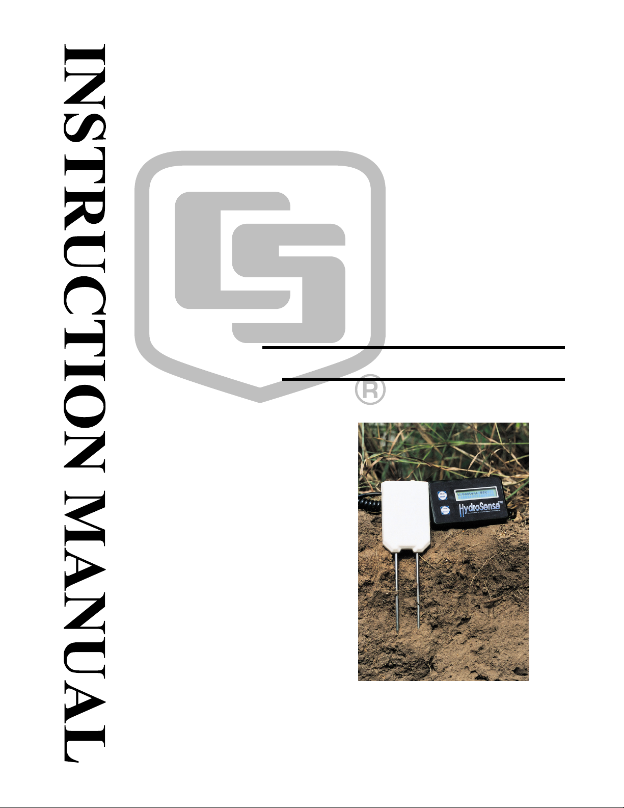
1-1 The HydroSense system consists of the CS620 sensor (left),
the CD620 display (right), and two rods ............................................. 1
4-1 Selecting probe rod length....................................................................... 5
5-1 HydroSense display in Water Deficit Mode ............................................ 7
5-2 Selecting the site, lower (0) and upper (100) reference levels................. 8
5-3 Relative water content and deficit for example application..................... 9
8-1 Rear view of the HydroSense display unit with battery cover removed .... 13
8-2 Newer CS620 rod design (left) and older CS620 rod design (right) ..... 14
Tables
B.2-1 Sample Water Content Data............................................................. B-1
ii
HydroSense Soil Water Measurement System (CD620, CS620)
1. General Description
1.1 Introduction
FIGURE 1-1. The HydroSense system consists of
the CS620 sensor (left), the CD620 display (right), and two rods.
The components of the HydroSense system are the CS620 sensor, CD620
display, and two rods. Campbell Scientific offers 12-cm long rods (pn 18591)
or 20-cm long rods (pn 18592). The sensor, display, and rods are purchased
separately.
The HydroSense Soil Water Content Measurement System provides a simple
and portable means to measure soil water content. Two modes of operation
allow the display of volumetric water content in percent or relative water
content based on lower and upper reference values chosen by the user. The
relative water content is complemented by deficit values showing how much
water is required to bring water content to the upper reference value.
The combined probe and display weight is approximately 600 gm (1.3 lb).
Two alkaline AAA batteries in the handheld display provide enough power for
several thousand readings. A measurement is made by fully inserting the
probe rods into the soil and pressing a READ button and takes less than onehalf second. To save power, HydroSense automatically goes into sleep mode
after approximately two minutes of inactivity.
1

HydroSense Soil Water Measurement System (CD620, CS620)
1.2 HydroSense Modes
The Water Content Measurement Mode displays the measurement result as
percent volumetric water content and shows the period of the probe output in
milliseconds.
In the Water Deficit Mode, HydroSense measurements are taken at lower and
upper water contents chosen by the user and stored in memory as reference
values. The reference values are then applied to subsequent measurements to
determine the amount of water that must be added to bring the soil to the upper
water content. The relative water content based on the reference values is also
displayed.
See Sections 4 and 5 for detailed operating information.
2. Specifications
CD620 HydroSense Display Unit
Measurement % Volumetric Water Content
Resolution 1.0%
Environmental Splash resistant
Display 16 character, 2 line LCD
Keypad Two button membrane keypad
Power 2 x AAA 1.5 VDC alkaline batteries
Current Consumption Sleep <50 μA
Idle 1.5 mA
Measurement 70 mA
Battery Life Approximately 12 months
Dimensions 120 (w) x 73 (d) x 24 (h) mm (4.7” x 2.9” x 0.9”)
Weight 166 g (7 oz) includes batteries
CS620 Water Content Reflectometer
Accuracy ±3.0% volumetric water content with electrical
conductivity <2 dS m
Range 0% to saturation*
Stabilization time Instantaneous
Response time <50 milliseconds
Power requirement
100 milliamps at 5 ±0.03 volts
-1
.
2
Output Square wave with ±2.5 VDC amplitude
Dimensions Head 105 x 70 x 18 mm (4.1” x 2.8” x 0.7”)
Rods 120 or 200 mm length , 5 mm diameter, 32
mm spacing

HydroSense Soil Water Measurement System (CD620, CS620)
Weight 390 g (14 oz)
Cable Spiral cable, 200 cm extended.
*saturation is typically around 50% volumetric water content
3. Unpacking and Setup
• Remove the protective strip from the display window.
• Screw the rods into the threaded inserts of the CS620. Use the open-
ended wrench to tighten the nut on the end of the rods, ensuring that the
rods are securely attached. Threads should be clean before rods are
screwed into the CS620 (see Section 8.2).
NOTE
CAUTION
In December 2009, the rods were redesigned and now include a
nut. The 7/16th open-ended wrench is shipped with the CS620
HydroSense sensor for tightening and loosening this nut. Rods
shipped prior to December 2009 had a disc-shaped collar instead
of a nut.
• Connect the probe to the CD620 display unit by mating the coiled cable
connector to the connector on the display unit.
The connector is a push-pull type and can be damaged if
twisted while connecting or disconnecting.
• The READ button is used
1) to power-up HydroSense,
2) to make a measurement,
3) and in combination with the MENU button to select options.
Press the READ button and check that HydroSense is in Water
READ
ENTER
Content Measurement Mode. The display should be similar
to the following graphic but may have different numerical
values.
VWC 0% P12cm
Period 0.77ms
• An NC after VWC indicates the probe is not properly connected.
• If it is necessary to change operating modes, the HydroSense must be in
sleep mode (no display). The unit automatically goes into sleep mode
after approximately two minutes of inactivity. To change modes, press
3
HydroSense Soil Water Measurement System (CD620, CS620)
and hold the MENU button then press the READ button. Release both
buttons. Unless the mode is changed again, HydroSense will be in Water
Content Measurement Mode when READ is next pressed to wake the
unit.
• While holding the probes so rods are in free air, press READ. The VWC
displayed should be between -3% and 3%.
VWC 0% P12cm
Period 0.77ms
In Water Content Measurement Mode, MENU is used to select
MENU
SELECT
• To save power, HydroSense automatically goes into sleep mode after
approximately two minutes of inactivity. Pressing the READ button wakes
the unit and makes a measurement.
the rod length. In the Water Deficit Mode, MENU is used to
select the site number and to store reference water content
values.
4. Water Content Measurement Mode
4.1 Introduction
The Water Content Measurement Mode displays the measurement result as
percent volumetric water content and also shows the period of the probe output
in milliseconds. The HydroSense operating system applies standard
calibrations to convert the probe response to volumetric water content. The
calibrations were derived from laboratory measurements in typical agronomic
soils. Section 6.2 discusses the soil factors which can affect probe response
such that standard calibrations do not work well.
4.2 Display Information
Volumetric
Water
Content
VWC 22% P12cm
Period 0.93ms
Probe
Output
Period
Probe
Rod Length
4
HydroSense Soil Water Measurement System (CD620, CS620)
The two-line display provides the following information
1) The volumetric water content in percent (VWC). See Appendix A for
definition of water content.
2) Which probe rod length is selected (see Section 4.4 for rod length
selection).
3) The period of the square wave output from the probe in milliseconds.
4.3 Description of Water Content Measurement Mode
The Water Content Measurement Mode applies calibration coefficients to
the output of the probe to give volumetric water content in percent. The
calibration coefficients reside in the operating system and were determined by
the manufacturer. The calibration was derived from laboratory measurements
in typical agronomic soils. See Section 6.2 for discussion of HydroSense use
in high salinity, high clay or other atypical materials.
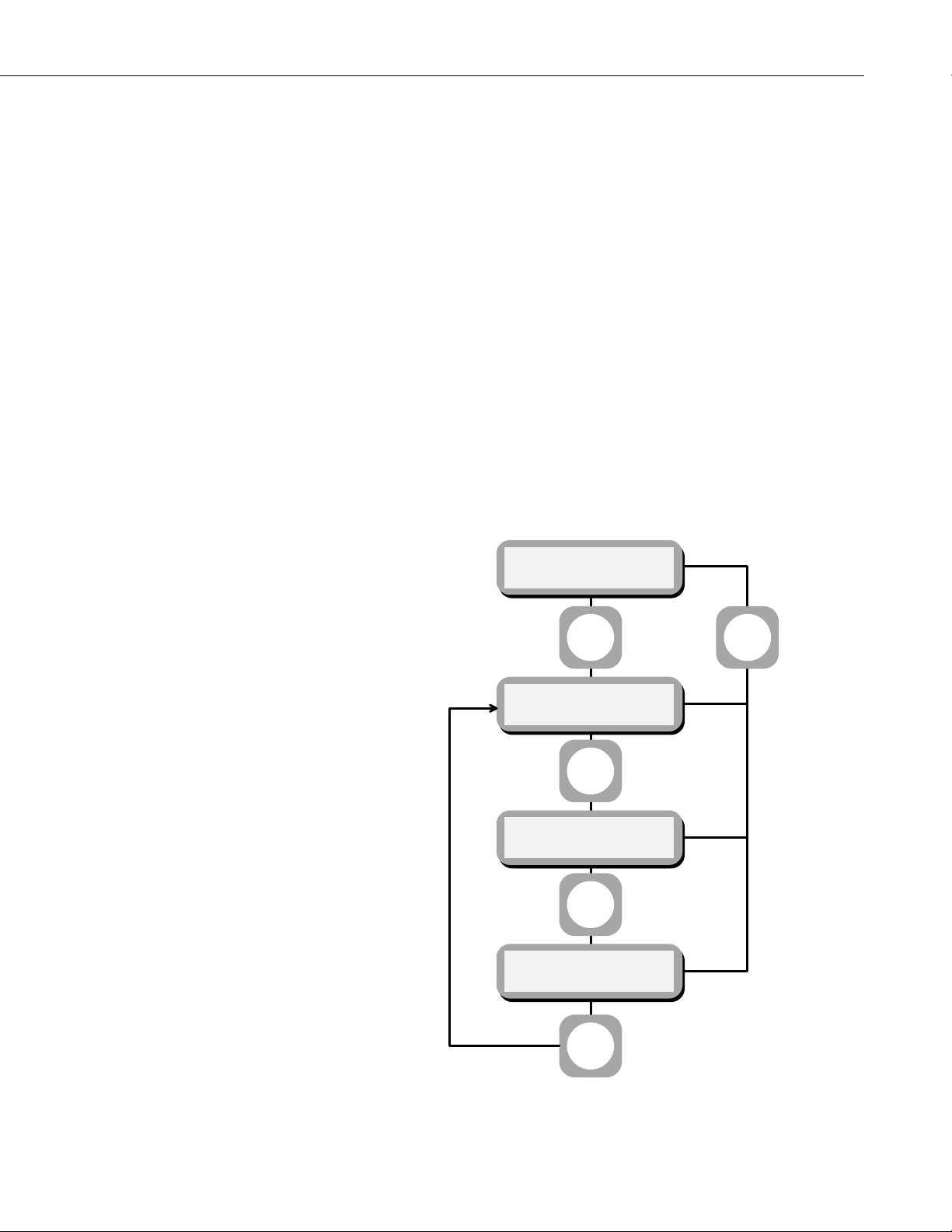
4.4 Selecting Probe Rod Length
VWC 22% P12cm
Period 0.93ms
MENU
SELECT
Probe
Exit
MENU
SELECT
Probe
12cm
MENU
SELECT
Probe
20cm
READ
ENTER
MENU
SELECT
FIGURE 4-1. Selecting probe rod length
5
 Loading...