

Page 1

INSTRUCTION MANUAL
Model HMP35C Temperature
and Relative Humidity Probe
Revision: 1/99
Copyright (c) 1990-1999
Campbell Scientific, Inc.
Page 2

Warranty and Assistance
The HMP35C TEMPERATURE AND RELATIVE HUMIDITY PROBE
is warranted by CAMPBELL SCIENTIFIC, INC. to be free from defects in
materials and workmanship under normal use and service for twelve (12)
months from date of shipment unless specified otherwise. Batteries have no
warranty. CAMPBELL SCIENTIFIC, INC.'s obligation under this warranty is
limited to repairing or replacing (at CAMPBELL SCIENTIFIC, INC.'s option)
defective products. The customer shall assume all costs of removing,
reinstalling, and shipping defective products to CAMPBELL SCIENTIFIC,
INC. CAMPBELL SCIENTIFIC, INC. will return such products by surface
carrier prepaid. This warranty shall not apply to any CAMPBELL
SCIENTIFIC, INC. products which have been subjected to modification,
misuse, neglect, accidents of nature, or shipping damage. This warranty is in
lieu of all other warranties, expressed or implied, including warranties of
merchantability or fitness for a particular purpose. CAMPBELL SCIENTIFIC,
INC. is not liable for special, indirect, incidental, or consequential damages.
Products may not be returned without prior authorization. The following
act information is for US and International customers residing in countries
cont
served by Campbell Scientific, Inc. directly. Affiliate companies handle
repairs for customers within their territories. Please visit
www.campbellsci.com to determine which Campbell Scientific company
serves your country. To obtain a Returned Materials Authorization (RMA),
contact CAMPBELL SCIENTIFIC, INC., phone (435) 753-2342. After an
applications engineer determines the nature of the problem, an RMA number
will be issued. Please write this number clearly on the outside of the shipping
container. CAMPBELL SCIENTIFIC's shipping address is:
CAMPBELL SCIENTIFIC, INC.
RMA#_____
815 W
Logan, Ut
CAMPBELL SCIENTIFIC, INC. does not accept collect calls.
est 1800 North
ah 84321-1784
Page 3

MODEL HMP35C
TEMPERATURE AND RELATIVE HUMIDITY PROBE
1. GENERAL DESCRIPTION
The HMP35C Temperature and Relative
Humidity probe contains a thermistor for
measuring temperature and a Vaisala
capacitive polymer H chip for measuring relative
humidity.
The -L option on the model HMP35C
Temperature and Relative Humidity probe
(HMP35C-L) indicates that the cable length is
user specified. This manual refers to the
sensor as the HMP35C.
2. SPECIFICATIONS
Operating Temperature: -35° to +60°C
Storage Temperature: -40° to +80°C
Probe Length: 25.4 cm (10 in.)
Probe Body Diameter: 2.5 cm (1 in.)
Filter: 0.2 µm Teflon membrane
Filter Diameter: 1.9 cm (0.75 in.)
Power Consumption: < 4 mA
Supply Voltage (via CSI switching circuit):
7 to 35 VDC
Settling Time after power is switched on:
0.15 seconds
2.1 TEMPERATURE SENSOR
Sensor: thermistor (100 kΩ @ 25°C)
Temperature Measurement Range:
-35° to +55°C
Thermistor Interchangeability Error:
Typically < ±0.2°C over 0° to +60°C, ±0.4°C
@ -35°C
Polynomial Linearization Error:
< ±0.5°C over -35° to +50°C
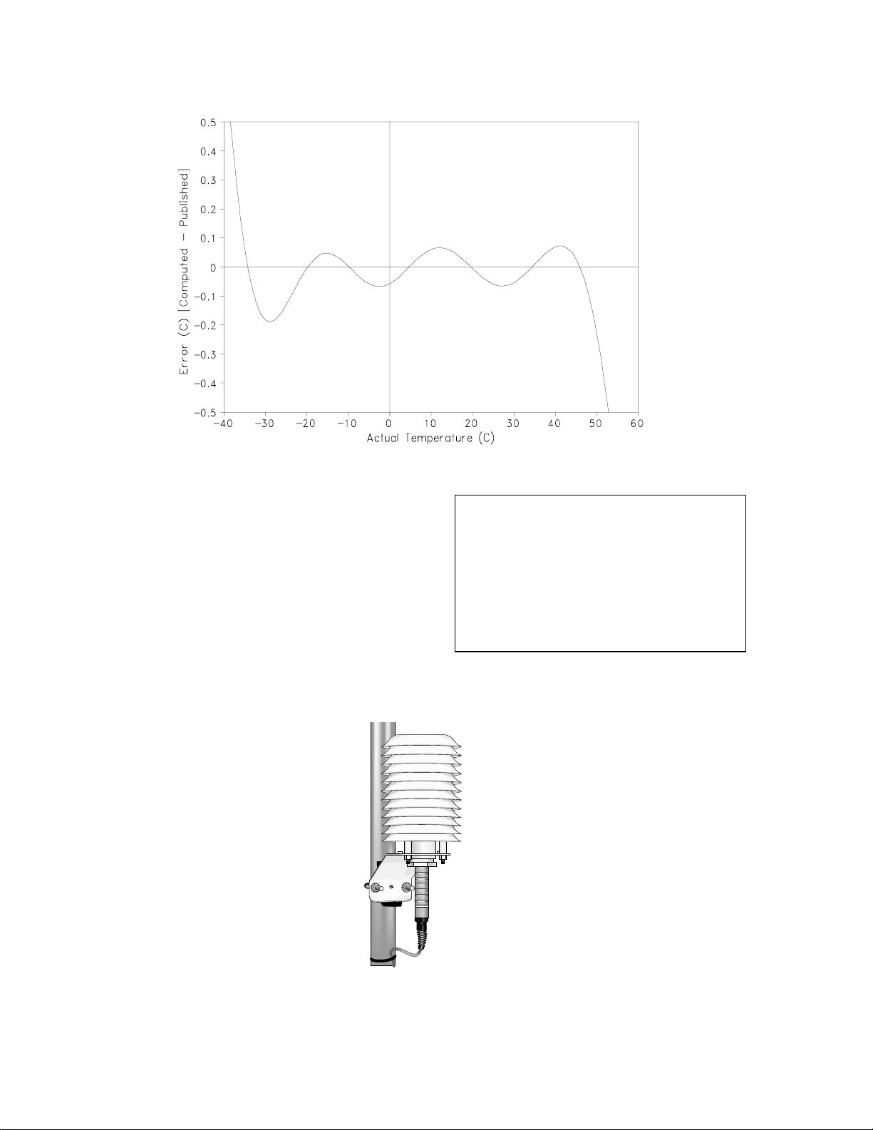
2.1.1 Temperature Sensor Accuracy
The overall probe accuracy is a combination of
the thermistor's interchangeability specification,
the precision of the bridge resistors, and the
polynomial error. In a "worst case" all errors
add to an accuracy of ±0.4°C over the range of
-24°C to 48°C and ±0.9°C over the range of
-38° to 53°C. The major error component is the
interchangeability specification of the
thermistor, tabulated in Table 1. For the range
of 0° to 50°C the interchangeability error is
predominantly offset and can be determined
with a single point calibration. Compensation
can then be done with an offset entered in the
measurement instruction. The bridge resistors
are 0.1% tolerance with a 10 ppm temperature
coefficient. Polynomial errors are tabulated in
Table 2 and plotted in Figure 1.
TABLE 1. Thermistor Interchangeability
Temperature
(°C)
−40
−30
−20
−10
0 to +50 0.20
TABLE 2. Polynomial Error
Temperature
Range(°C)
−40 to +56 <±1.0°C
−38 to +53 <±0.5°C
−24 to +48 <±0.1°C
2.2 RELATIVE HUMIDITY SENSOR
Sensor: Vaisala capacitive polymer H chip
Relative Humidity Measurement Range:
0 to 100% non-condensing
RH Output Signal Range:
0.002 to 1 VDC
Accuracy at 20°C
±2% RH (0 to 90% Relative Humidity)
±3% RH (90 to 100% Relative Humidity)
Temperature Dependence of Relative Humidity
Measurement: ±0.04% RH/°C
Typical Long Term Stability:
Better than 1% RH per year
Response Time (at 20°C, 90% response to
steep change in humidity):
15 seconds with membrane filter
Temperature
Tolerance (±°C)
0.40
0.40
0.32
0.25
Error (°C)
1
Page 4
HMP35C TEMPERATURE AND RH PROBE
FIGURE 1. Error Produced by Polynomial Fit to Published Values
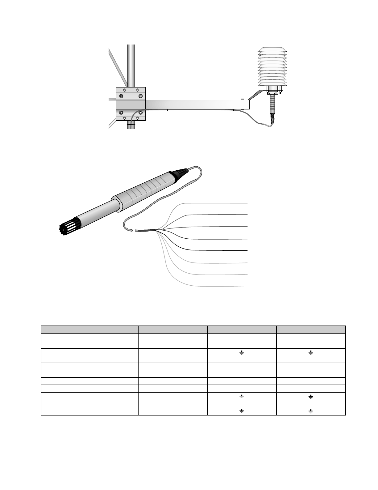
3. INSTALLATION
The HMP35C must be housed inside a radiation
shield when used in the field. The 41002
Radiation Shield (Figure 2) mounts to a
CM6/CM10 tripod or UT10 tower. The UT018
mounting arm and UT12VA Radiation Shield
mount to a UT30 tower (Figure 3).
A lead length of 6 feet allows the HMP35C to be
mounted at a 2 meter height on a CM6/CM10
tripod. Use a lead length of 9 feet for the UT10
tower or a UT30 tower respectively.
NOTE: The black outer jacket of the cable
is Santoprene® rubber. This compound was
chosen for its resistance to temperature
extremes, moisture, and UV degradation.
However, this jacket will support
combustion in air. It is rated as slow
burning when tested according to U.L. 94
H.B. and will pass FMVSS302. Local fire
codes may preclude its use inside buildings.
FIGURE 2. HMP35C and 41002 Radiation Shield on a
CM6/CM10 Tripod Mast or UT10 Tower Leg
2
Page 5
HMP35C TEMPERATURE AND RH PROBE
FIGURE 3. HMP35C with UT018 Mounting Bracket and Crossarm and
UT12VA Radiation Shield Mounted on a UT30 Tower
Orange Temperature Signal
Green Relative Humidity Signal
White Temperature Signal Reference
Black Temperature Excitation
Yellow Power Control
Red Power
Purple RH Signal, Power, & Control Reference
Clear Shield
FIGURE 4. HMP35C Probe to Datalogger Connections
TABLE 3. Datalogger Connections
Description Color CR10(X), CR500 CR23X 21X, CR7
Temperature Orange Single-Ended Input Single-Ended Input Single-Ended Input
Relative Humidity Green Single-Ended Input Single-Ended Input Single-Ended Input
Temperature Signal
White AG
Reference
Temperature
Black Excitation Channel Excitation Channel Excitation Channel
Excitation
Power Control Yellow Control Port Control Port Control Port
Power Red 12 V 12 V 12 V
RH Signal, Power, &
Purple AG
Control Reference
Shield Clear G
3
Page 6

HMP35C TEMPERATURE AND RH PROBE
4. WIRING
Connections to Campbell Scientific dataloggers
are given in Table 3. The probe is measured by
two single-ended input channels, one for
temperature and one for relative humidity. A
single excitation channel is used for the
temperature measurement.
The number of HMP35C probes that can be
excited by one excitation channel is physically
limited by the number of lead wires that can be
inserted into a single excitation terminal
(approximately 6).
5. EXAMPLE PROGRAMS
This section is for users who write their own
datalogger programs. A datalogger program to
measure this sensor can be created using
Campbell Scientific’s Short Cut Program Builder
software. You do not need to read this section to
use Short Cut.
The temperature is measured using a singleended analog measurement and an excitation
channel (Instruction 11). The relative humidity is
measured using a single-ended analog
measurement (Instruction 1). Tables 4 and 5
provide calibration information for temperature
and relative humidity.
CAUTION: Do no turn the HMP35C on
before measuring the thermistor. Doing so
will induce a transient signal spike on the
thermistor leads that will result in an
erroneous temperature measurement.
Always measure the HMP35C temperature
first.
TABLE 4. Calibration for Temperature
Units Multiplier
(degrees mV-1)
Celsius 1 0
Fahrenheit 1.8 32
TABLE 5. Calibration for Relative Humidity
Units Multiplier
(% mV-1)
Percent 0.1 0
Fraction 0.001 0
Offset
(degrees)
Offset
(%)
Description Color CR10(X)
Temperature Orange SE 3 (2H)
Relative Humidity Green SE 4 (2L)
Temperature Signal Reference White AG
Temperature Excitation Black E1
Power Control Yellow C1
Power Red 12 V
RH Signal, Power, & Control Reference Purple AG
Shield Clear G
Example 1. Sample CR10(X) Program measuring HMP35C
Temperature and Relative Humidity
;Measure the HMP35C temperature.
;
01: Temp (107) (P11)
1: 1 Reps
2: 3 SE Channel
3: 1 Excite all reps w/E1
4: 1 Loc [ T_C ]
5: 1 Mult
6: 0 Offset
;Turn the HMP35C on.
;
02: Do (P86)
1: 41 Set Port 1 High
TABLE 6. Wiring for Example 1
;Orange wire (SE 3), White wire (AG)
;Black wire (EX 1)
;See Table 4 for alternate multipliers
;See Table 4 for alternate offsets
;Yellow wire (C1)
4
Page 7

HMP35C TEMPERATURE AND RH PROBE
;Pause 150 milliseconds, before making the measurement, so the
;probe can stabilize on the true relative humidity.
;
03: Excitation with Delay (P22)
1: 1 Ex Channel
2: 0 Delay W/Ex (units = 0.01 sec)
3: 15 Delay After Ex (units = 0.01 sec)
4: 0 mV Excitation
;Measure the HMP35C relative humidity.
;
04: Volt (SE) (P1)
1: 1 Reps
2: 5 2500 mV Slow Range
3: 4 SE Channel
4: 2 Loc [ RH_pct ]
5: 0.1 Mult
6: 0 Offset
;CR500 (2500 mV); CR23X (1000 mV); 21X, CR7 (5000 mV)
;Green wire (SE 4), Purple wire (AG)
;See Table 5 for alternate multipliers
;Turn the HMP35C off.
;
05: Do (P86)
1: 51 Set Port 1 Low
;Yellow wire (C1)
6. LONG LEAD LENGTHS
When long lead lengths are required, the
measurement settling time for the temperature
measurement must be increased. For
HMP35Cs with lead lengths greater than 300
feet, use the DC Half Bridge instruction
(Instruction 4) with a 20 millisecond delay to
measure the thermistor (Example 2).
TABLE 7. Wiring for Example 2
Description Color CR10(X)
Temperature Orange SE 3 (2H)
Relative Humidity Green SE 4 (2L)
Temperature Signal Reference White AG
Temperature Excitation Black E1
Power Control Yellow C1
Power Red 12 V
RH Signal, Power, & Control Reference Purple AG
Shield Clear G
Long lead lengths cause errors in the measured
relative humidity. The approximate error in
relative humidity is 0.6% RH per 100 feet of
cable length. When long lead lengths are
required and the above errors in relative
humidity are unacceptable, use the HMP45C
temperature and humidity probe.
5
Page 8

HMP35C TEMPERATURE AND RH PROBE
Example 2. Sample CR10(X) Program measuring HMP35C Temperature
using DC Half Bridge with Delay
;Measure the HMP35C thermistor.
;
01: Excite-Delay (SE) (P4)
1: 1 Reps
2: 2 7.5 mV Slow Range
3: 3 SE Channel
4: 1 Excite all reps w/Ex 1
5: 2 Delay (units 0.01 sec)
6: 2000 mV Excitation
7: 1 Loc [ T_C ]
8: 0.4 Mult
9: 0 Offset
;CR500 (7.5 mV); CR23X (10 mV); 21X, CR7 (15 mV)
;Orange wire (SE 3), White wire (AG)
;Black wire (EX 1)
;CR500, CR23X (2000 mV); 21X, CR7 (4000 mV)
;CR500, CR23X (0.4); 21X, CR7 (0.2)
;Compute the temperature in degrees Celsius.
;
02: Polynomial (P55)
1: 1 Reps
2: 1 X Loc [ T_C ]
3: 1 F(X) Loc [ T_C ]
4: -53.46 C0
5: 90.807 C1
6: -83.257 C2
7: 52.283 C3
8: -16.723 C4
9: 2.211 C5
;Apply the temperature multiplier.
;
03: Z=X*F (P37)
1: 1 X Loc [ T_C ]
2: 1 F
3: 1 Z Loc [ T_C ]
;See Table 4 for alternate multipliers
;Apply the temperature offset.
;
04: Z=X+F (P34)
1: 1 X Loc [ T_C ]
2: 0 F
3: 1 Z Loc [ T_C ]
;See Table 4 for alternate offsets
;Turn the HMP35C on.
;
05: Do (P86)
1: 41 Set Port 1 High
;Yellow wire (C1)
;Pause 150 milliseconds, before making the measurement, so the
;probe can stabilize on the true relative humidity.
;
06: Excitation with Delay (P22)
1: 1 Ex Channel
2: 0 Delay W/Ex (units = 0.01 sec)
3: 15 Delay After Ex (units = 0.01 sec)
4: 0 mV Excitation
6
Page 9

;Measure the HMP35C relative humidity.
;
07: Volt (SE) (P1)
1: 1 Reps
2: 5 2500 mV Slow Range
3: 4 SE Channel
4: 2 Loc [ RH_pct ]
5: 0.1 Mult
6: 0 Offset
;Turn the HMP35C off.
;
08: Do (P86)
1: 51 Set Port 1 Low
HMP35C TEMPERATURE AND RH PROBE
;CR500 (2500 mV); CR23X (1000 mV); 21X, CR7 (5000 mV)
;Green wire (SE 4), Purple wire (AG)
;See Table 5 for alternate multipliers
;Yellow wire (C1)
6.1 TEMPERATURE
Understanding the following details are not
required for the general operation of the
HMP35C with Campbell Scientific’s
dataloggers.
Whenever an analog input is switched into the
datalogger measurement circuitry prior to
making a measurement, a finite amount of time
is required for the signal to stabilize to its
correct value. The rate at which the signal
settles is determined by the input settling time
constant which is a function of both the source
resistance and input capacitance. Campbell
Scientific dataloggers allow a 450 µs settling
time before initiating the measurement. In most
applications, this settling time is adequate, but
additional wire capacitance associated with long
sensor leads can increase the settling time
constant so that measurement errors occur.
See Section 13 in the datalogger manuals for
more information.
6.2 RELATIVE HUMIDITY
Understanding the following details are not
required for the general operation of the
HMP35C with Campbell Scientific’s
dataloggers.
The relative humidity signal reference and the
power reference (black) are the same lead in
the HMP35C. When the measuring relative
humidity, both the signal and power references
are connected to ground at the datalogger. The
signal/power reference lead serves as the
return path for 12 V. There will be a voltage
drop along this lead because the wire itself has
resistance. The HMP35C draws approximately
4 mA when it is powered. The wire used in the
HMP35C (P/N 9721) has a resistance of 13.9
Ω/1000 feet. Using Ohm’s law, the voltage drop
), along the signal reference/power ground
(V
d
lead, is given by Eq. (1).
V
=∗
d
IR
=∗
mA ft
4 139 1000
=
mV ft
556 1000
.
Ω
.
This voltage drop will raise the apparent
temperature and relative humidity because the
difference between the signal and signal
reference, at the datalogger, has increased by
V
. The approximate error in relative humidity is
d
0.6% RH per 100 feet of cable length.
7. ELECTRICALLY NOISY ENVIRONMENTS
AC power lines can be the source of electrical
noise. If the datalogger is in an electronically
noisy environment, the HMP35C temperature
measurement should be made with the AC half
bridge instruction (Instruction 5) with the 60 Hz
rejection integration option on the CR10(X),
CR500, and CR23X. Use the slow integration on
the 21X and CR7.
Use the 60 Hz rejection integration option when
measuring the relative humidity with the singleended analog measurement on the CR10(X),
CR500, and CR23X. Use the slow integration on
the 21X and CR7.
(1)
7
Page 10

HMP35C TEMPERATURE AND RH PROBE
TABLE 8. Wiring for Example 3
Description Color CR10(X)
Temperature Orange SE 3 (2H)
Relative Humidity Green SE 4 (2L)
Temperature Signal Reference White AG
Temperature Excitation Black E1
Power Control Yellow C1
Power Red 12 V
RH Signal, Power, & Control Reference Purple AG
Shield Clear G
Example 3. CR10(X) Program that Measures the HMP35C
in an Electrically Noisy Environment
;Measure the HMP35C thermistor.
;
01: AC Half Bridge (P5)
1: 1 Reps
2: 22 7.5 mV 60 Hz Rejection Range
3: 3 SE Channel
4: 1 Excite all reps w/Ex 1
5: 2000 mV Excitation
6: 1 Loc [ T_C ]
7: 800 Mult
8: 0 Offset
;Orange wire (SE 3), White wire (AG)
;Black wire (EX 1)
;CR500, CR23X (2000 mV); 21X, CR7 (4000 mV)
;CR500 (7.5 mV); CR23X (10 mV)
;21X, CR7 (15 mV)
;Compute the temperature in degrees Celsius.
;
02: Polynomial (P55)
1: 1 Reps
2: 1 X Loc [ T_C ]
3: 1 F(X) Loc [ T_C ]
4: -53.46 C0
5: 90.807 C1
6: -83.257 C2
7: 52.283 C3
8: -16.723 C4
9: 2.211 C5
;Apply the temperature multiplier.
;
03: Z=X*F (P37)
1: 1 X Loc [ T_C ]
2: 1 F
3: 1 Z Loc [ T_C ]
;See Table 4 for alternate multipliers
;Apply the temperature offset.
;
04: Z=X+F (P34)
1: 1 X Loc [ T_C ]
2: 0 F
3: 1 Z Loc [ T_C ]
;See Table 4 for alternate offsets
8
Page 11

HMP35C TEMPERATURE AND RH PROBE
;Turn the HMP35C on.
;
05: Do (P86)
1: 41 Set Port 1 High
;Yellow wire (C1)
;Pause 150 milliseconds, before making the measurement, so the
;probe can stabilize on the true relative humidity.
;
06: Excitation with Delay (P22)
1: 1 Ex Channel
2: 0 Delay W/Ex (units = 0.01 sec)
3: 15 Delay After Ex (units = 0.01 sec)
4: 0 mV Excitation
;Measure the HMP35C relative humidity.
;
07: Volt (SE) (P1)
1: 1 Reps
2: 25 2500 mV 60 Hz Rejection Range
;CR500 (2500 mV); CR23X (1000 mV)
;21X, CR7 (5000 mV)
3: 4 SE Channel
;Green wire (SE 4), Purple wire (AG)
4: 2 Loc [ RH_pct ]
5: 0.1 Mult
;See Table 5 for alternate multipliers
6: 0 Offset
;Turn the HMP35C off.
;
08: Do (P86)
1: 51 Set Port 1 Low
8. ABSOLUTE HUMIDITY
The HMP35C measures the relative humidity.
Relative humidity is defined by the equation
below:
e
RH
where RH is the relative humidity, e is the vapor
pressure in kPa , and e
pressure in kPa. The vapor pressure, e, is an
absolute measure of the amount of water vapor
in the air and is related to the dew point
temperature. The saturation vapor pressure is
the maximum amount of water vapor that air
can hold at a given air temperature. The
relationship between dew point and vapor
pressure, and air temperature and saturation
vapor pressure are given by Goff and Gratch
(1946), Lowe (1977), and Weiss (1977).
When the air temperature increases, so does
the saturation vapor pressure. Conversely, a
decrease in air temperature causes a
corresponding decrease in saturation vapor
100
=∗ (2)
e
s
is the saturation vapor
s
;Yellow wire (C1)
pressure. It follows then from Eq. (2) that a
change in air temperature will change the
relative humidity, without causing a change in
absolute humidity.
For example, for an air temperature of 20°C
and a vapor pressure of 1.17 kPa, the
saturation vapor pressure is 2.34 kPa and the
relative humidity is 50%. If the air temperature
is increased by 5°C and no moisture is added or
removed from the air, the saturation vapor
pressure increases to 3.17 kPa and the relative
humidity decreases to 36.9%. After the
increase in air temperature, the air can hold
more water vapor. However, the actual amount
of water vapor in the air has not changed.
Thus, the amount of water vapor in the air,
relative to saturation, has decreased.
Because of the inverse relationship between
relative humidity and air temperature, finding
the mean relative humidity is meaningless. A
more useful quantity is the mean vapor
pressure. The mean vapor pressure can be
computed on-line by the datalogger (Example
4).
9
Page 12

HMP35C TEMPERATURE AND RH PROBE
TABLE 9. Wiring for Example 4
Description Color CR10(X)
Temperature Orange SE 3 (2H)
Relative Humidity Green SE 4 (2L)
Temperature Signal Reference White AG
Temperature Excitation Black E1
Power Control Yellow C1
Power Red 12 V
RH Signal, Power, & Control Reference Purple AG
Shield Clear G
Example 4. Sample CR10(X) Program that Computes Vapor Pressure
and Saturation Vapor Pressure
;Measure the HMP35C temperature.
;
01: Temp (107) (P11)
1: 1 Reps
2: 3 SE Channel
3: 1 Excite all reps w/E1
4: 1 Loc [ T_C ]
5: 1 Mult
6: 0 Offset
;Orange wire (SE 3), White wire (AG)
;Black wire (EX 1)
;See Table 4 for alternate multipliers
;See Table 4 for alternate offsets
;Turn the HMP35C on.
;
02: Do (P86)
1: 41 Set Port 1 High
;Yellow wire (C1)
;Pause 150 milliseconds, before making the measurement, so the
;probe can stabilize on the true relative humidity.
;
03: Excitation with Delay (P22)
1: 1 Ex Channel
2: 0 Delay W/Ex (units = 0.01 sec)
3: 15 Delay After Ex (units = 0.01 sec)
4: 0 mV Excitation
;Measure the HMP35C relative humidity.
;
04: Volt (SE) (P1)
1: 1 Reps
2: 5 2500 mV Slow Range
3: 4 SE Channel
4: 2 Loc [ RH_frac ]
5: 0.001 Mult
6: 0 Offset
;CR500 (2500 mV); CR23X (1000 mV); 21X, CR7 (5000 mV)
;Green wire (SE 4), Purple wire (AG)
;See Table 5 for alternate multipliers
;Turn the HMP35C off.
;
05: Do (P86)
1: 51 Set Port 1 Low
;Yellow wire (C1)
10
Page 13

HMP35C TEMPERATURE AND RH PROBE
;Compute the saturation vapor pressure in kPa. The temperature must be in degrees Celsius.
;
06: Saturation Vapor Pressure (P56)
1: 1 Temperature Loc [ T_C ]
2: 3 Loc [ e_sat ]
;Compute the vapor pressure in kPa. Relative humidity must be a fraction.
;
07: Z=X*Y (P36)
1: 3 X Loc [ e_sat ]
2: 2 Y Loc [ RH_frac ]
3: 4 Z Loc [ e_kPa ]
9. INSTRUCTION 11 DETAILS
Understanding the details in this section are not
necessary for using the HMP35C Probe with
Campbell Scientific's dataloggers.
Instruction 11 outputs a precise 2 VAC
excitation (4 V with the 21X) and measures the
voltage drop due to the sensor resistance
(Figure 5). The thermistor resistance changes
with temperature. Instruction 11 calculates the
ratio of voltage measured to excitation voltage
(Vs/Vx) which relates to resistance as shown
below:
V
s
=
VR
xs
where Rs is the resistance of the thermistor.
See the measurement section of the datalogger
manual for more information on bridge
measurements.
Instruction 11 then calculates temperature using
a fifth order polynomial equation correlating
Vs/Vx with temperature. The polynomial
coefficients are given in Table 10. The
polynomial input is (Vs/Vx)∗800. Resistance
and datalogger output at several temperatures
are shown in Table 11.
1000
++
249000 1000
(2)
Coefficient Value
C0 -53.4601
C1 90.807
C2 -83.257
C3 52.283
C4 -16.723
C5 2.211
10. MAINTENANCE
The HMP35C Probe requires minimal
maintenance. Check monthly to make sure the
radiation shield is free from debris. The black
screen on the sensor's end should also be
checked.
When installed in close proximity to the ocean
or other bodies of salt water (e.g., Great Salt
Lake), a coating of salt (mostly NaCl) may build
up on the radiation shield, sensor, filter and
even the chip. NaCl has an affinity for water.
The humidity over a saturated NaCl solution is
75%. A buildup of salt on the filter or chip will
delay or destroy the response to atmospheric
humidity.
The filter can be rinsed gently in distilled water.
If necessary, the chip can be removed and
rinsed as well. Do not scratch the chip while
cleaning.
FIGURE 5. Thermistor Probe Schematic
TABLE 10. Polynomial Coefficients
Recalibrate the HMP35C annually. Obtain an
RMA number before returning the HMP35C to
Campbell Scientific for recalibration.
11
Page 14

HMP35C TEMPERATURE AND RH PROBE
TABLE 11. Temperature, Resistance, and
Datalogger Output
Temperature
(°C)
-40.00 4067212 -39.18
-38.00 3543286 -37.55
-36.00 3092416 -35.83
-34.00 2703671 -34.02
-32.00 2367900 -32.13
-30.00 2077394 -30.18
-28.00 1825568 -28.19
-26.00 1606911 -26.15
-24.00 1416745 -24.11
-22.00 1251079 -22.05
-20.00 1106485 -20.00
-18.00 980100 -17.97
-16.00 869458 -15.95
-14.00 772463 -13.96
-12.00 687276 -11.97
-10.00 612366 -10.00
-8.00 546376 -8.02
-6.00 488178 -6.05
-4.00 436773 -4.06
-2.00 391294 -2.07
0.00 351017 -0.06
2.00 315288 1.96
4.00 283558 3.99
6.00 255337 6.02
8.00 230210 8.04
10.00 207807 10.06
12.00 187803 12.07
14.00 169924 14.06
16.00 153923 16.05
18.00 139588 18.02
20.00 126729 19.99
22.00 115179 21.97
24.00 104796 23.95
26.00 95449 25.94
28.00 87026 27.93
30.00 79428 29.95
32.00 72567 31.97
34.00 66365 33.99
36.00 60752 36.02
38.00 55668 38.05
40.00 51058 40.07
42.00 46873 42.07
44.00 43071 44.05
46.00 39613 46.00
48.00 36465 47.91
50.00 33598 49.77
52.00 30983 51.59
54.00 28595 53.35
56.00 26413 55.05
58.00 24419 56.70
60.00 22593 58.28
Resistance
(Ω)
Output
(°C)
11. REFERENCES
Goff, J. A. and S. Gratch, 1946: Low-pressure
properties of water from -160° to 212°F,
Trans. Amer. Soc. Heat. Vent. Eng.
125-164.
Lowe, P. R., 1977: An approximating
polynomial for the computation of saturation
vapor pressure,
J. Appl. Meteor.
103.
Weiss, A., 1977: Algorithms for the calculation
of moist air properties on a hand calculator,
Amer. Soc. Ag. Eng.
, 20, 1133-1136.
, 16, 100-
, 51,
12
Page 15

This is a bla nk page.
Page 16

Campbell Scientific Companies
Campbell Scientific, Inc. (CSI)
815 West 1800 North
Logan, Utah 84321
UNITED STATES
www.campbellsci.com
info@campbellsci.com
Campbell Scientific Africa Pty. Ltd. (CSAf)
PO Box 2450
Somerset West 7129
SOUTH AFRICA
www.csafrica.co.za
sales@csafrica.co.za
Campbell Scientific Australia Pty. Ltd. (CSA)
PO Box 444
Thuringo wa Cent ra l
QLD 4812 AUSTRALIA
www.campbellsci.com.au
info@campbellsci.com.au
Campbell Scientific do Brazil Ltda . (CSB)
Rua Luisa Crapsi Orsi, 15 Butantã
CEP: 005543-000 São Paulo SP BRAZIL
www.campbellsci.com.br
suporte@campbellsci.com.br
Campbell Scientific Canada Corp. (CSC)
11564 - 149th Street NW
Edmonton, Alberta T5M 1W7
CANADA
www.campbellsci.ca
dataloggers@campbellsci.ca
Campbell Scientific Ltd. (CSL)
Campbell Park
80 Hathern Road
Shepshed, Loughborough LE12 9GX
UNITED KINGDOM
www.campbellsci.co.uk
sales@campbellsci.co.uk
Campbell Scientific Ltd. (France)
Miniparc du Verger - Bat. H
1, rue de Terre Neuve - Les Ulis
91967 COURTABOEUF CEDEX
FRANCE
www.campbellsci.fr
campbell.scientific@wanadoo.fr
Campbell Scientific Spain, S. L.
Psg. Font 14, local 8
08013 Barcelona
SPAIN
www.campbellsci.es
info@campbellsci.es
Please visit www.campbellsci.com to obtain contact information for your local US or International representative.
 Loading...