

Page 1
INSTRUCTION MANUAL
Model HFP01SC Self-Calibrating
Copyright © 2002- 2014
Soil Heat Flux Plate
Revision: 3/14
Campbell Scientific, Inc.
Page 2

Page 3

Warranty
“PRODUCTS MANUFACTURED BY CAMPBELL SCIENTIFIC, INC. are
warranted by Campbell Scientific, Inc. (“Campbell”) to be free from defects in
materials and workmanship under normal use and service for twelve (12)
months from date of shipment unless otherwise specified in the corresponding
Campbell pricelist or product manual. Products not manufactured, but that are
re-sold by Campbell, are warranted only to the limits extended by the original
manufacturer. Batteries, fine-wire thermocouples, desiccant, and other
consumables have no warranty. Campbell’s obligation under this warranty is
limited to repairing or replacing (at Campbell’s option) defective products,
which shall be the sole and exclusive remedy under this warranty. The
customer shall assume all costs of removing, reinstalling, and shipping
defective products to Campbell. Campbell will return such products by surface
carrier prepaid within the continental United States of America. To all other
locations, Campbell will return such products best way CIP (Port of Entry)
INCOTERM® 2010, prepaid. This warranty shall not apply to any products
which have been subjected to modification, misuse, neglect, improper service,
accidents of nature, or shipping damage. This warranty is in lieu of all other
warranties, expressed or implied. The warranty for installation services
performed by Campbell such as programming to customer specifications,
electrical connections to products manufactured by Campbell, and product
specific training, is part of Campbell’s product warranty. CAMPBELL
EXPRESSLY DISCLAIMS AND EXCLUDES ANY IMPLIED
WARRANTIES OF MERCHANTABILITY OR FITNESS FOR A
PARTICULAR PURPOSE. Campbell is not liable for any special, indirect,
incidental, and/or consequential damages.”
Page 4

Assistance
Products may not be returned without prior authorization. The following
contact information is for US and international customers residing in countries
served by Campbell Scientific, Inc. directly. Affiliate companies handle
repairs for customers within their territories. Please visit
www.campbellsci.com to determine which Campbell Scientific company serves
your country.
To obtain a Returned Materials Authorization (RMA), contact CAMPBELL
SCIENTIFIC, INC., phone (435) 227-9000. After an applications engineer
determines the nature of the problem, an RMA number will be issued. Please
write this number clearly on the outside of the shipping container. Campbell
Scientific’s shipping address is:
CAMPBELL SCIENTIFIC, INC.
RMA#_____
815 West 1800 North
Logan, Utah 84321-1784
For all returns, the customer must fill out a “Statement of Product Cleanliness
and Decontamination” form and comply with the requirements specified in it.
The form is available from our web site at www.campbellsci.com/repair. A
completed form must be either emailed to repair@campbellsci.com or faxed to
(435) 227-9106. Campbell Scientific is unable to process any returns until we
receive this form. If the form is not received within three days of product
receipt or is incomplete, the product will be returned to the customer at the
customer’s expense. Campbell Scientific reserves the right to refuse service on
products that were exposed to contaminants that may cause health or safety
concerns for our employees.
Page 5

Table of Contents
PDF viewers: These page numbers refer to the printed version of this document. Use the
PDF reader bookmarks tab for links to specific sections.
1. Introduction ................................................................. 1
2. Cautionary Statements ............................................... 1
3. Initial Inspection ......................................................... 1
4. Overview ...................................................................... 1
5. Specifications ............................................................. 2
6. Installation ................................................................... 3
6.1 Placement in Soil.................................................................................. 3
6.2 Wiring .................................................................................................. 6
6.3 Programming ........................................................................................ 6
Example 1. Sample CR3000 Program Using a Differential
6.3.1
Measurement Instruction ........................................................... 6
6.3.2 Example 2. Sample CR10(X) Program Using a Single-Ended
Measurement Instruction ........................................................... 9
6.3.3 Example 3. Sample CR23X Program Using a Differential
Measurement Instruction ......................................................... 13
6.3.4 Example 4. Sample CR10X Program Using External Power
and Relay ................................................................................. 17
6.4 Soil Heat Flux and Storage ................................................................. 22
6.5 In-Situ Calibration Theory ................................................................. 23
7. Maintenance .............................................................. 24
8. References ................................................................ 24
Figures
6-1. Placement of heat flux plates ............................................................... 3
6-2. HFP01SC plate ..................................................................................... 4
Tables
6-1. Datalogger Connections for a Single-Ended Measurement ................. 5
6-2. Datalogger Connections for a Differential Measurement ..................... 5
6-3. Wiring for Example 1 ........................................................................... 6
6-4. Wiring for Example 2 ........................................................................... 9
6-5. Wiring for Example 3 ......................................................................... 13
6-6. Sensor Wiring for Example 4 ............................................................. 17
6-7. Datalogger-to-A21REL-12 Wiring for Example 4 ............................. 17
6-8. Hukseflux and Campbell Scientific Variable Names ......................... 24
i
Page 6

Table of Contents
ii
Page 7

Model HFP01SC
Self-Calibrating Soil Heat Flux Plate
1. Introduction
The HFP01SC Self-Calibrating Heat Flux Sensor measures soil heat flux,
typically for energy-balance or Bowen-ratio flux systems. It is intended for
applications requiring the highest possible degree of measurement accuracy.
At least two sensors are required for each site to provide spatial averaging.
Sites with heterogeneous media may require additional sensors.
Before installing the HFP01SC, please study
• Section 2, Cautionary Statements
• Section 3, Initial Inspection
The installation procedure is provided in Section 6, Installation.
2. Cautionary Statements
• Care should be taken when opening the shipping package to not damage or
cut the cable jacket. If damage to the cable is suspected, consult with a
Campbell Scientific applications engineer.
• Although the HFP01SC is rugged, it should be handled as a precision
scientific instrument.
3. Initial Inspection
• Upon receipt of the HFP01SC, inspect the packaging and contents for
damage. File damage claims with the shipping company.
• The model number and cable length are printed on a label at the
connection end of the cable. Check this information against the shipping
documents to ensure the correct product and cable length are received.
• The HFP01SC is shipped with a calibration sheet and an instruction
manual or a ResourceDVD.
4. Overview
The HFP01SC Soil Heat Flux plate consists of a thermopile and a film heater.
The thermopile measures temperature gradients across the plate. During the insitu field calibration, the film heater is used to generate a heat flux through the
plate. The amount of power used to generate the calibration heat flux is
measured by the datalogger. Each plate is individually calibrated, at the
factory, to output flux.
1
Page 8

Model HFP01SC Self-Calibrating Soil Heat Flux Plate
In order to measure soil heat flux at the surface, several HFP01SCs are used to
measure the soil heat flux at a depth of eight centimeters. A TCAV, Averaging
Soil Thermocouple, is used to measure the temporal change in temperature of
the soil layer above the HFP01SC. Finally, a CS650, CS655, or CS616 water
content reflectometer is used to measure the soil water content. The temporal
change in soil temperature and soil water content are used to compute the soil
storage term.
The -L option on the model HFP01SC Soil Heat Flux Plate (HFP01SC-L)
indicates that the cable length is user specified. The HFP01SC-L has two
cables; the first cable is the signal output cable and the second is the heater
input cable. Two analog inputs are required to measure the HFP01SC-L. This
manual refers to the sensor as the HFP01SC.
The sensor’s cable can terminate in:
• Pigtails that connect directly to a Campbell Scientific datalogger
(option –PT).
• Connector that attaches to a prewired enclosure (option –PW). Refer
to www.campbellsci.com/prewired-enclosures for more information.
5. Specifications
Features:
• Corrects for errors due to differences in thermal conductivity between
the sensor and the surrounding medium, temperature variations, and
slight sensor instabilities
• Compatible with most of our dataloggers
• Uses Van den Bos-Hoeksema self-calibration method to provide
high-degree of measurement accuracy
Compatibility
Dataloggers: CR800 series
CR1000
CR3000
CR5000
CR9000(X)
CR7X
CR10(X)
CR23X
21X
Operating Temperature: –30° to +70°C
Storage Temperature: –30° to +70°C
2
Plate Thickness: 5 mm (0.2 in)
Plate Diameter: 80 mm (3.15 in)
Average Power Consumption: 0.02 to 0.04 W
Page 9
Model HFP01SC Self-Calibrating Soil Heat Flux Plate
Partial emplacement of the HFP01SC and the TCAV
Sensor: Thermopile and film heater
Heater Voltage Input: 9 to 15 Vdc
Heater Voltage Output: 0 to 2 Vdc
Expected Accuracy: ±3% of reading
6. Installation
6.1 Placement in Soil
Sensitivity (nominal): 50 µV W
Sensor Resistance (nominal): 2 Ω
Heater Resistance (nominal): 100 Ω
Duration of Calibration: ±3 min. @ 1.5 W; typically done every 3 to
6 hours
Weight without Cable: 200 g (7.05 oz)
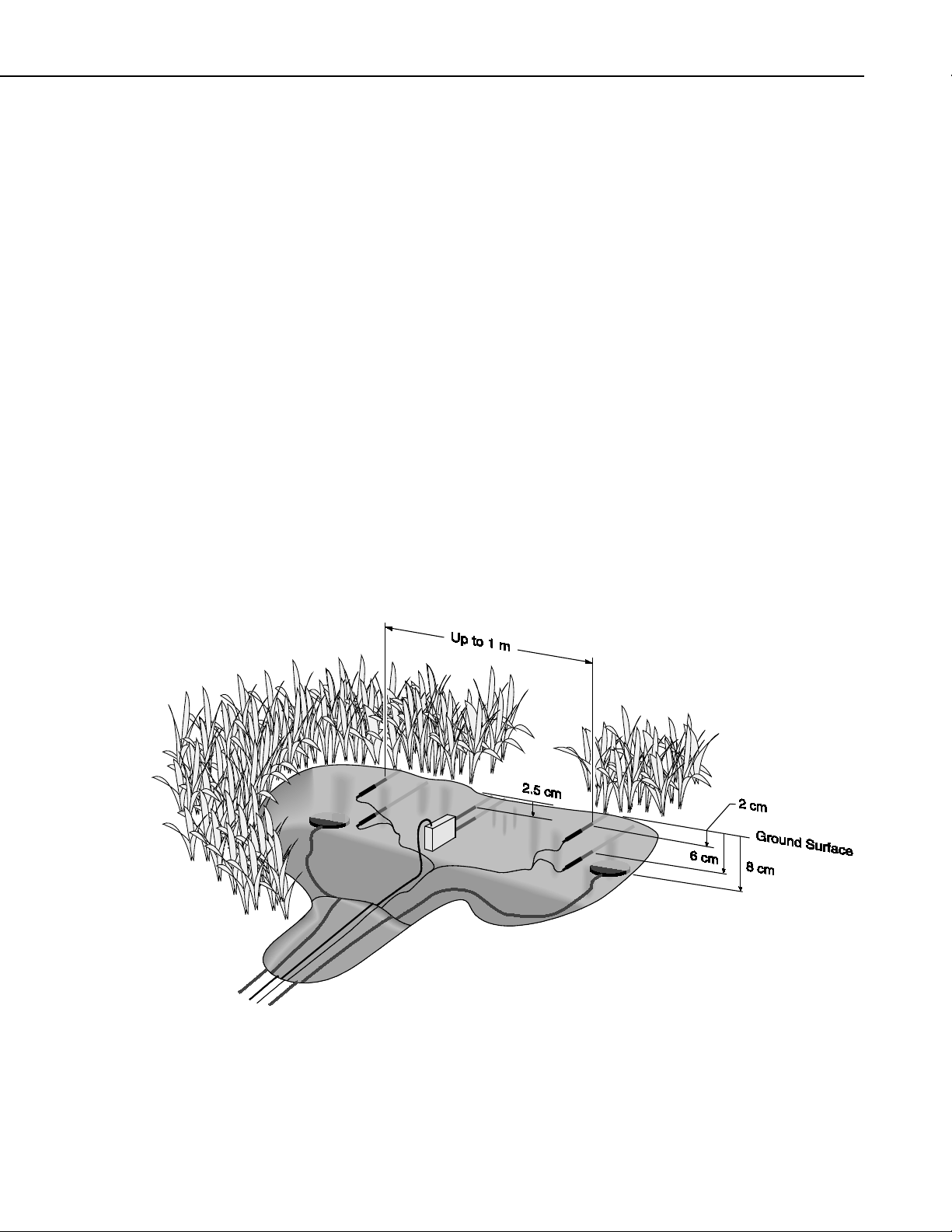
The HFP01SC soil heat flux plates, the TCAV averaging soil temperature
probes, and the CS616, Water Content Reflectometer, are installed as shown in
FIGURE 6-1.
–1 m–2
sensors is shown for illustration purposes. All sensors
must be completely inserted into the soil face before
the hole is backfilled.
FIGURE 6-1. Placement of heat flux plates
3
Page 10
Model HFP01SC Self-Calibrating Soil Heat Flux Plate
NOTE
CAUTION
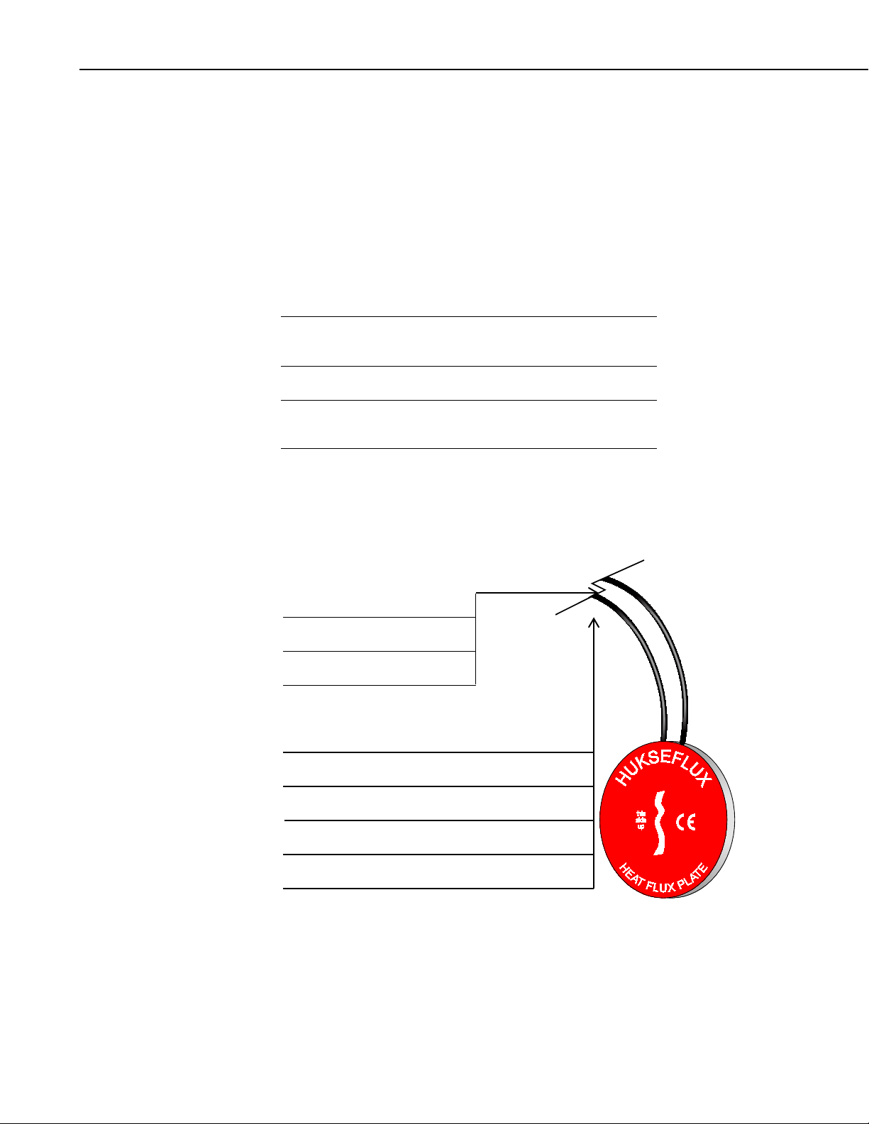
Signal (White)
Signal Reference (Green)
Shield (Clear)
Heater Resis
Heater Resistor Signal Reference (Purple)
Shield (Clear)
Power (Red)
Power Reference (Black)
The location of the heat flux plates and thermocouples should represent the
area of study. If the ground cover is extremely varied, it may be necessary to
have additional sensors to provide a valid spatial average of soil heat flux.
Use a small shovel to make a vertical slice in the soil. Excavate the soil to one
side of the slice. Keep this soil intact to ensure replacement with minimal
disruption.
The sensors are installed in the undisturbed face of the hole. Measure the
sensor depths from the top of the hole. With a small knife, make a horizontal
cut eight centimeters below the surface into the undisturbed face of the hole.
Insert the heat flux plate into the horizontal cut.
Install the HFP01SC in the soil such that the side with the text
“this side up” is facing the sky.
In order for the HFP01SC to make quality soil heat flux
measurements, the plate must be in full contact with the soil.
Never run the sensors leads directly to the surface. Rather, bury the sensor
leads a short distance back from the hole to minimized thermal conduction on
the lead wire. Replace the excavated soil into its original position after all the
sensors are installed.
tor Signal (Yellow)
4
FIGURE 6-2. HFP01SC plate
Page 11

Model HFP01SC Self-Calibrating Soil Heat Flux Plate
TABLE 6-1. Datalogger Connections for a Single-Ended Measurement
TABLE 6-2. Datalogger Connections for a Differential Measurement
Description
Color
CR10X
CR3000, CR5000,
CR23X, CR9000(X),
CR7, 21X
CR800, CR850,
CR1000
Sensor Signal White Single-Ended Input Single-Ended Input Single-Ended Input
Sensor Signal
Reference
Green AG
Shield Clear G
Heater Resistor Signal Yellow Single-Ended Input Single-Ended Input Single-Ended Input
Heater Resistor Signal
Reference
Purple AG
Shield Clear G
Power Red SW12 SW12 SW12
Power Reference Black G G G
External Power Control Jumper
Wire
SW12-CTRL to
Control Port
External Power Control
Not Needed
External Power Control
Not Needed
Description
Color
CR10(X)
CR3000, CR5000,
CR23X, CR9000(X),
CR7, 21X
CR800, CR850,
CR1000
Sensor Signal White Differential Input (H) Differential Input (H) Differential Input (H)
Sensor Signal
Green Differential Input (L) Differential Input (L) Differential Input (L)
Reference
Shield Clear G
Heater Resistor Signal Yellow Differential Input (H) Differential Input (H) Differential Input (H)
Heater Resistor Signal
Purple Differential Input (L) Differential Input (L) Differential Input (L)
Reference
Shield Clear G
Power Red SW12 SW12 SW12
Power Reference Black G G G
External Power
Control
Jumper
Wire
SW12-CTRL to
Control Port
External Power Control
Not Needed
External Power
Control Not Needed
5
Page 12

Model HFP01SC Self-Calibrating Soil Heat Flux Plate
TABLE 6-3. Wiring for Example 1
NOTE
6.2 Wiring
Connections to Campbell Scientific dataloggers are given in FIGURE 6-1,
TABLE 6-1, and TABLE 6-2. The output of the HFP01SC can be measured
using a single-ended analog measurement (VoltSE() or Instruction 1),
however, a differential analog measurement (VoltDiff() or Instruction 2) is
recommended.
The wiring convention is that the white wire is positive with respect to the
green wire, when energy is flowing through the transducer from the side with
the text “this side up” to the other side.
The switched 12 Vdc port can source enough current to calibrate
four HFP01SC plates. If additional HFP01SC plates are needed,
an external relay is required to power the additional plates (see
example 4).
For dataloggers without a SW12V output (CR7X, 21X and CR10), a relay
(A21REL-12) is required for the in-situ calibration (see Example 4).
6.3 Programming
The HFP01SC has a nominal calibration of 15 W m-2 mV-1. Each sensor is
accompanied by a calibration certificate. Each sensor also has a unique
calibration label on it. The label is located on the pigtail end of the sensor
leads.
6.3.1 Example 1. Sample CR3000 Program Using a Differential Measurement Instruction
TABLE 6-3 provides the wiring for Example 1.
Description Color CR3000
Sensor Signal #1 White 9H
Sensor Signal Reference #1 Green 9L
Shield #1 Clear
Sensor Signal #2 White 10H
Sensor Signal Reference #2 Green 10L
Shield #2 Clear
Sensor Signal #3 White 11H
Sensor Signal Reference #3 Green 11L
6
Shield #3 Clear
Sensor Signal #4 White 12H
Sensor Signal Reference #4 Green 12L
Shield #4 Clear
Page 13

Model HFP01SC Self-Calibrating Soil Heat Flux Plate
Heater Resistor Signal #1 Yellow 13H
Heater Resistor Signal Reference #1 Purple
Shield #1 Clear
Power #1 Red SW12-1
Power Reference #1 Black G
Heater Resistor Signal #2 Yellow 13L
Heater Resistor Signal Reference #2 Purple
Shield #2 Clear
Power #2 Red SW12-1
Power Reference #2 Black G
Heater Resistor Signal #3 Yellow 14H
Heater Resistor Signal Reference #3 Purple
Shield #3 Clear
Power #3 Red SW12-1
Power Reference #3 Black G
Heater Resistor Signal #4 Yellow 14L
Heater Resistor Signal Reference #4 Purple
Shield #4 Clear
Power #4 Red SW12-1
'CR3000 Series Datalogger
Const OUTPUT_INTERVAL = 30 'Online mean output interval in minutes.
Const CAL_INTERVAL = 1440 'HFP01SC insitu calibration interval (minutes).
Const END_CAL = OUTPUT_INTERVAL-1 'End HFP01SC insitu calibration one minute before the next Output.
Const HFP01SC_CAL_1 = 15 'Unique multiplier for HFP01SC #1 (1000/sensitivity).
Const HFP01SC_CAL_2 = 15 'Unique multiplier for HFP01SC #2 (1000/sensitivity).
Const HFP01SC_CAL_3 = 15 'Unique multiplier for HFP01SC #3 (1000/sensitivity).
Const HFP01SC_CAL_4 = 15 'Unique multiplier for HFP01SC #4 (1000/sensitivity).
'*** Variables ***
Public shf(4)
Public shf_cal(4)
Units shf = W/m^2
Units shf_cal = W/(m^2 mV)
'HFP01SC calibration variables.
Dim shf_mV(4)
Dim shf_mV_0(4)
Dim shf_mV_180(4)
Dim shf_mV_end(4)
Dim V_Rf(4)
Dim V_Rf_180(4)
Dim shf_cal_on_f As Boolean
Dim sw12_1_state As Boolean 'State of the switched 12Vdc port 1.
Dim ii As Long
DataTable (mean,TRUE,100)
DataInterval (0,OUTPUT_INTERVAL,Min,10)
Average (4,shf(1),IEEE4,shf_cal_on_f)
Sample (4,shf_cal(1),IEEE4)
EndTable
7
Page 14

Model HFP01SC Self-Calibrating Soil Heat Flux Plate
BeginProg
'HFP01SC factory calibration in W/(m^2 mV) = 1000/sensitivity.
shf_cal(1) = HFP01SC_CAL_1
shf_cal(2) = HFP01SC_CAL_2
shf_cal(3) = HFP01SC_CAL_3
shf_cal(4) = HFP01SC_CAL_4
Scan (1,Sec,3,0)
'Measure the HFP01SC soil heat flux plates.
VoltDiff (shf_mV(1),4,mV50C,9,TRUE,0,_60Hz,1,0)
'Apply calibration to HFP01SC soil heat flux plates.
For ii = 1 To 4
shf(ii) = shf_mV(ii)*shf_cal(ii)
Next ii
'Power the HFP01SC heaters.
PortSet (9,sw12_1_state)
'Measure voltage across the heater (Rf_V).
VoltSe (V_Rf(1),4,mV5000,25,TRUE,0,_60Hz,0.001,0)
CallTable (mean)
'Begin HFP01SC calibration on a fixed interval.
If ( IfTime (1,CAL_INTERVAL,Min) ) Then
shf_cal_on_f = TRUE
Move (shf_mV_0(1),4,shf_mV(1),4)
sw12_1_state = TRUE
EndIf
If ( IfTime (4,CAL_INTERVAL,Min) ) Then
Move (shf_mV_180(1),4,shf_mV(1),4)
Move (V_Rf_180(1),4,V_Rf(1),4)
sw12_1_state = FALSE
EndIf
If ( IfTime (END_CAL,CAL_INTERVAL,Min) ) Then
Move (shf_mV_end(1),4,shf_mV(1),4)
'Compute new HFP01SC calibration factors.
For ii = 1 To 4
shf_cal(ii) = V_Rf_180(ii)*V_Rf_180(ii)*128.7/ABS (((shf_mV_0(ii)+shf_mV_end(ii))/2)-shf_mV_180(ii))
Next ii
shf_cal_on_f = FALSE
EndIf
NextScan
EndProg
8
Page 15

Model HFP01SC Self-Calibrating Soil Heat Flux Plate
TABLE 6-4. Wiring for Example 2
6.3.2 Example 2. Sample CR10(X) Program Using a Single-Ended Measurement Instruction
TABLE 6-4 provides the wiring for Example 2.
Description Color CR10(X)
Sensor Signal White 1H
Sensor Signal Reference Green AG
Shield Clear G
Heater Resistor Signal Yellow 1L
Heater Resistor Signal
Reference
Shield Clear G
Power Red SW12
Power Reference Black G
External Power Control jumper wire SW12-CTRL to
;{CR10X}
;
*Table 1 Program
01: 1 Execution Interval (seconds)
;Measure HFP01SC on smaller range.
;
1: Volt (SE) (P1)
1: 1 Reps
2: 22 7.5 mV 60 Hz Rejection Range
3: 1 SE Channel
4: 2 Loc [ shf_mV ]
5: 1 Mult
6: 0 Offset
;Measure HFP01SC on larger range.
;
2: Volt (SE) (P1)
1: 1 Reps
2: 23 25 mV 60 Hz Rejection Range
3: 1 SE Channel
4: 8 Loc [ shf_mV_a ]
5: 1 Mult
6: 0 Offset
;Load in the factory calibration.
;
3: If (X<=>F) (P89)
1: 3 X Loc [ cal ]
2: 1 =
3: 0 F
4: 30 Then Do
Purple AG
C8
9
Page 16

Model HFP01SC Self-Calibrating Soil Heat Flux Plate
;Factory calibration in W/(m^2 mV) = 1000/sensitivity.
;
4: Z=F (P30)
1: 1 F ; <- Enter the unique calibration here
2: 0 Exponent of 10
3: 3 Z Loc [ cal ]
5: End (P95)
;Use data from the larger measurement range.
;
6: If (X<=>F) (P89)
1: 2 X Loc [ shf_mV ]
2: 4 <
3: -99990 F
4: 30 Then Do
7: Z=X (P31)
1: 8 X Loc [ shf_mV_a ]
2: 2 Z Loc [ shf_mV ]
8: End (P95)
;Apply custom calibration to the raw soil heat flux measurement.
;
9: Z=X*Y (P36)
1: 2 X Loc [ shf_mV ]
2: 3 Y Loc [ cal ]
3: 1 Z Loc [ shf ]
;Output data.
;
10: If time is (P92)
1: 0 Minutes (Seconds --) into a
2: 20 Interval (same units as above)
3: 10 Set Output Flag High (Flag 0)
11: Real Time (P77)
1: 0110 Day,Hour/Minute (midnight = 0000)
12: Resolution (P78)
1: 1 High Resolution
;Do not include the calibration data in the soil heat flux.
;
13: If Flag/Port (P91)
1: 18 Do if Flag 8 is High
2: 19 Set Intermed. Proc. Disable Flag High (Flag 9)
14: Average (P71)
1: 1 Reps
2: 1 Loc [ shf ]
15: Do (P86)
1: 29 Set Intermed. Proc. Disable Flag Low (Flag 9)
16: Sample (P70)
1: 1 Reps
2: 3 Loc [ cal ]
;Add other processing here.
;Call calibration routine.
;
17: Do (P86)
1: 8 Call Subroutine 8
10
Page 17

*Table 2 Program
02: 0 Execution Interval (seconds)
*Table 3 Subroutines
;Calibration routine.
;
1: Beginning of Subroutine (P85)
1: 8 Subroutine 8
;Perform in-situ calibration.
;
2: If time is (P92)
1: 1 Minutes (Seconds --) into a
2: 180 Interval (same units as above)
3: 30 Then Do
3: Z=X (P31)
1: 2 X Loc [ shf_mV ]
2: 4 Z Loc [ mV_0 ]
;Begin heating for calibration.
;
4: Do (P86)
1: 48 Set Port 8 High
;Used to filter data during and after calibration.
;
5: Do (P86)
1: 18 Set Flag 8 High
6: End (P95)
;End site calibration three minutes after calibration started.
;
7: If time is (P92)
1: 4 Minutes (Seconds --) into a
2: 180 Interval (same units as above)
3: 30 Then Do
;Measure voltage across current shunt resistor (10 ohm 1% 0.25 W 50
;ppm/deg C) during calibration. This measurement is used to
;compute power.
;
8: Volt (SE) (P1)
1: 1 Reps
2: 25 2500 mV 60 Hz Rejection Range
3: 2 SE Channel
4: 7 Loc [ V_Rf ]
5: .001 Mult
6: 0 Offset
9: Z=X (P31)
1: 2 X Loc [ shf_mV ]
2: 5 Z Loc [ mV_180 ]
;Turn off the soil heat flux plate heater.
;
10: Do (P86)
1: 58 Set Port 8 Low
11: End (P95)
Model HFP01SC Self-Calibrating Soil Heat Flux Plate
11
Page 18

Model HFP01SC Self-Calibrating Soil Heat Flux Plate
;Stop filtering data.
;
12: If time is (P92)
1: 39 Minutes (Seconds --) into a
2: 180 Interval (same units as above)
3: 30 Then Do
13: Do (P86)
1: 28 Set Flag 8 Low
;Compute in-situ calibration.
;
14: Z=X (P31)
1: 2 X Loc [ shf_mV ]
2: 6 Z Loc [ mV_end ]
15: Z=X*Y (P36)
1: 7 X Loc [ V_Rf ]
2: 7 Y Loc [ V_Rf ]
3: 3 Z Loc [ cal ]
16: Z=X*F (P37)
1: 3 X Loc [ cal ]
2: 128.7 F
3: 3 Z Loc [ cal ]
17: Z=X+Y (P33)
1: 4 X Loc [ mV_0 ]
2: 6 Y Loc [ mV_end ]
3: 9 Z Loc [ work ]
18: Z=X*F (P37)
1: 9 X Loc [ work ]
2: .5 F
3: 9 Z Loc [ work ]
19: Z=X-Y (P35)
1: 9 X Loc [ work ]
2: 5 Y Loc [ mV_180 ]
3: 9 Z Loc [ work ]
20: Z=ABS(X) (P43)
1: 9 X Loc [ work ]
2: 9 Z Loc [ work ]
21: Z=X/Y (P38)
1: 3 X Loc [ cal ]
2: 9 Y Loc [ work ]
3: 3 Z Loc [ cal ]
22: End (P95)
23: End (P95)
End Program
-Input Locations1 shf
2 shf_mV
3 cal
4 mV_0
5 mV_180
6 mV_end
7 V_Rf
8 shf_mV_a
9 work
12
Page 19

Model HFP01SC Self-Calibrating Soil Heat Flux Plate
TABLE 6-5. Wiring for Example 3
6.3.3 Example 3. Sample CR23X Program Using a Differential Measurement Instruction
TABLE 6-5 provides the wiring for Example 3.
Description Color CR23X
Sensor Signal White 9H
Sensor Signal Reference Green 9L
Shield Clear
Heater Resistor Signal Yellow 10H
Heater Resistor Signal Reference Purple 10L
Shield Clear
Power Red SW12
Power Reference Black G
;{CR23X}
;
*Table 1 Program
01: 1 Execution Interval (seconds)
;Measure HFP01SC on smaller range.
;
1: Volt (Diff) (P2)
1: 1 Reps
2: 21 10 mV, 60 Hz Reject, Slow Range
3: 9 DIFF Channel
4: 2 Loc [ shf_mV ]
5: 1 Mult
6: 0 Offset
;Measure HFP01SC on larger range.
;
2: Volt (Diff) (P2)
1: 1 Reps
2: 25 5000 mV, 60 Hz Reject, Fast Range
3: 9 DIFF Channel
4: 8 Loc [ shf_mV_a ]
5: 1 Mult
6: 0 Offset
;Load in the factory calibration.
;
3: If (X<=>F) (P89)
1: 3 X Loc [ cal ]
2: 1 =
3: 0 F
4: 30 Then Do
13
Page 20

Model HFP01SC Self-Calibrating Soil Heat Flux Plate
;Factory calibration in W/(m^2 mV) = 1000/sensitivity.
;
4: Z=F (P30)
1: 1 F ; <- Enter the unique calibration here
2: 0 Exponent of 10
3: 3 Z Loc [ cal ]
5: End (P95)
;Use data from the larger measurement range.
;
6: If (X<=>F) (P89)
1: 2 X Loc [ shf_mV ]
2: 4 <
3: -99990 F
4: 30 Then Do
7: Z=X (P31)
1: 8 X Loc [ shf_mV_a ]
2: 2 Z Loc [ shf_mV ]
8: End (P95)
;Apply custom calibration to the raw soil heat flux measurement.
;
9: Z=X*Y (P36)
1: 2 X Loc [ shf_mV ]
2: 3 Y Loc [ cal ]
3: 1 Z Loc [ shf ]
;Output data.
;
10: If time is (P92)
1: 0 Minutes (Seconds --) into a
2: 20 Interval (same units as above)
3: 10 Set Output Flag High (Flag 0)
11: Real Time (P77)
1: 0110 Day,Hour/Minute (midnight = 0000)
12: Resolution (P78)
1: 1 High Resolution
;Do not include that calibration data in the soil heat flux.
;
13: If Flag/Port (P91)
1: 118 Do if Flag 18 is High
2: 19 Set Intermed. Proc. Disable Flag High (Flag 9)
14: Average (P71)
1: 1 Reps
2: 1 Loc [ shf ]
15: Do (P86)
1: 29 Set Intermed. Proc. Disable Flag Low (Flag 9)
16: Sample (P70)
1: 1 Reps
2: 3 Loc [ cal ]
;Add other processing here.
;Call calibration routine.
;
17: Do (P86)
1: 8 Call Subroutine 8
14
Page 21

Model HFP01SC Self-Calibrating Soil Heat Flux Plate
*Table 2 Program
02: 0 Execution Interval (seconds)
*Table 3 Subroutines
;Calibration routine.
;
1: Beginning of Subroutine (P85)
1: 8 Subroutine 8
;Perform in-situ calibration.
;
2: If time is (P92)
1: 1 Minutes (Seconds --) into a
2: 180 Interval (same units as above)
3: 30 Then Do
3: Z=X (P31)
1: 2 X Loc [ shf_mV ]
2: 4 Z Loc [ mV_0 ]
;Begin heating for calibration.
;
4: Do (P86)
1: 49 Turn On Switched 12V
;Used to filter data during and after calibration.
;
5: Do (P86)
1: 118 Set Flag 18 High
6: End (P95)
;End site calibration three minutes after calibration started.
;
7: If time is (P92)
1: 4 Minutes (Seconds --) into a
2: 180 Interval (same units as above)
3: 30 Then Do
;Measure voltage across current shunt resistor during calibration.
;This measurement is used to compute power.
;
8: Volt (Diff) (P2)
1: 1 Reps
2: 25 5000 mV, 60 Hz Reject, Fast Range
3: 10 DIFF Channel
4: 7 Loc [ V_Rf ]
5: .001 Mult
6: 0 Offset
9: Z=X (P31)
1: 2 X Loc [ shf_mV ]
2: 5 Z Loc [ mV_180 ]
;Turn off the soil heat flux plate heater.
;
10: Do (P86)
1: 59 Turn Off Switched 12V
11: End (P95)
;Stop filtering data.
;
12: If time is (P92)
1: 39 Minutes (Seconds --) into a
2: 180 Interval (same units as above)
3: 30 Then Do
15
Page 22

Model HFP01SC Self-Calibrating Soil Heat Flux Plate
13: Do (P86)
1: 218 Set Flag 18 Low
;Compute in-situ calibration.
;
14: Z=X (P31)
1: 2 X Loc [ shf_mV ]
2: 6 Z Loc [ mV_end ]
15: Z=X*Y (P36)
1: 7 X Loc [ V_Rf ]
2: 7 Y Loc [ V_Rf ]
3: 3 Z Loc [ cal ]
16: Z=X*F (P37)
1: 3 X Loc [ cal ]
2: 128.7 F
3: 3 Z Loc [ cal ]
17: Z=X+Y (P33)
1: 4 X Loc [ mV_0 ]
2: 6 Y Loc [ mV_end ]
3: 9 Z Loc [ work ]
18: Z=X*F (P37)
1: 9 X Loc [ work ]
2: .5 F
3: 9 Z Loc [ work ]
19: Z=X-Y (P35)
1: 9 X Loc [ work ]
2: 5 Y Loc [ mV_180 ]
3: 9 Z Loc [ work ]
20: Z=ABS(X) (P43)
1: 9 X Loc [ work ]
2: 9 Z Loc [ work ]
21: Z=X/Y (P38)
1: 3 X Loc [ cal ]
2: 9 Y Loc [ work ]
3: 3 Z Loc [ cal ]
22: End (P95)
23: End (P95)
End Program
-Input Locations1 shf
2 shf_mV
3 cal
4 mV_0
5 mV_180
6 mV_end
7 V_Rf
8 shf_mV_a
9 work
16
Page 23

Model HFP01SC Self-Calibrating Soil Heat Flux Plate
TABLE 6-6. Sensor Wiring for Example 4
Description
Color
CR10X
A21REL-12
Sensor Signal #1
White
1H Sensor Signal #2
White
1L Sensor Signal #3
White
2H Sensor Signal #4
White
2L Sensor Signal #5
White
3H Sensor Signal #6
White
3L All Signal References
Green
AG
All Shields
Clear G
Heater Resistor Signal #1
Yellow
4H Heater Resistor Signal #2
Yellow
4L Heater Resistor Signal #3
Yellow
5H Heater Resistor Signal #4
Yellow
5L
Heater Resistor Signal #5
Yellow
6H
Heater Resistor Signal #6
Yellow
6L
All Heater Resistor Signal References
Purple
AG
All Shields
Clear G
Sensor Power #1
Red
REL 1 NO
Sensor Power #2
Red
REL 1 NO
Sensor Power #3
Red
REL 2 NO
Sensor Power #4
Red
REL 2 NO
Sensor Power #5
Red
REL 3 NO
Sensor Power #6
Red
REL 3 NO
All Power Reference
Black G
TABLE 6-7. Datalogger-to-A21REL-12 Wiring for Example 4
Description
CR10X
A21REL-12
Power
12V
+ 12V
Power Reference G GROUND
Control
C8
CTRL 1
Control
jumper from CTRL 2 to CTRL 1
Control
jumper from CTRL 3 to CTRL 2
Power
jumper from REL 1 COM to +12V
Power
jumper from REL 2 COM to REL 1 COM
Power
jumper for REL 3 COM to REL 2 COM
6.3.4 Example 4. Sample CR10X Program Using External Power and Relay
TABLE 6-6 provides the sensor wiring for Example 4, and TABLE 6-7
provides the datalogger wiring for Example 4.
17
Page 24

Model HFP01SC Self-Calibrating Soil Heat Flux Plate
;{CR10X}
;
*Table 1 Program
01: 1 Execution Interval (seconds)
;Measure HFP01SC on smallest range.
;
1: Volt (SE) (P1)
1: 6 Reps
2: 22 7.5 mV 60 Hz Rejection Range
3: 1 SE Channel
4: 7 Loc [ shf_mV_1 ]
5: 1 Mult
6: 0 Offset
;Measure HFP01SC on larger range.
;
2: Volt (SE) (P1)
1: 6 Reps
2: 23 25 mV 60 Hz Rejection Range
3: 1 SE Channel
4: 44 Loc [ shf_mV_1a ]
5: 1 Mult
6: 0 Offset
;Load in the factory calibration.
;
3: If (X<=>F) (P89)
1: 13 X Loc [ cal_1 ]
2: 1 =
3: 0 F
4: 30 Then Do
;Factory calibration in W/(m^2 mV) = 1000/sensitivity.
;
4: Z=F (P30)
1: 1 F ;<- Enter the unique calibration for plate 1 here.
2: 0 Exponent of 10
3: 13 Z Loc [ cal_1 ]
5: Z=F (P30)
1: 1 F ;<- Enter the unique calibration for plate 2 here.
2: 0 Exponent of 10
3: 14 Z Loc [ cal_2 ]
6: Z=F (P30)
1: 1 F ;<- Enter the unique calibration for plate 3 here.
2: 0 Exponent of 10
3: 15 Z Loc [ cal_3 ]
7: Z=F (P30)
1: 1 F ;<- Enter the unique calibration for plate 4 here.
2: 0 Exponent of 10
3: 16 Z Loc [ cal_4 ]
8: Z=F (P30)
1: 1 F ;<- Enter the unique calibration for plate 5 here.
2: 0 Exponent of 10
3: 17 Z Loc [ cal_5 ]
9: Z=F (P30)
1: 1 F ;<- Enter the unique calibration for plate 6 here.
2: 0 Exponent of 10
3: 18 Z Loc [ cal_6 ]
10: End (P95)
18
Page 25

11: Beginning of Loop (P87)
1: 0 Delay
2: 6 Loop Count
;Use data from the larger measurement range.
;
12: If (X<=>F) (P89)
1: 7 -- X Loc [ shf_mV_1 ]
2: 4 <
3: -99990 F
4: 30 Then Do
13: Z=X (P31)
1: 44 -- X Loc [ shf_mV_1a ]
2: 7 -- Z Loc [ shf_mV_1 ]
14: End (P95)
;Apply custom calibration to raw soil heat flux measurement.
;
15: Z=X*Y (P36)
1: 7 -- X Loc [ shf_mV_1 ]
2: 13 -- Y Loc [ cal_1 ]
3: 1 -- Z Loc [ shf_1 ]
16: End (P95)
;Output data.
;
17: If time is (P92)
1: 0 Minutes (Seconds --) into a
2: 20 Interval (same units as above)
3: 10 Set Output Flag High (Flag 0)
18: Real Time (P77)^25251
1: 0110 Day,Hour/Minute (midnight = 0000)
19: Resolution (P78)
1: 1 High Resolution
;Do not include that calibration data in the soil heat flux.
;
20: If Flag/Port (P91)
1: 18 Do if Flag 8 is High
2: 19 Set Intermed. Proc. Disable Flag High (Flag 9)
21: Average (P71)^21989
1: 6 Reps
2: 1 Loc [ shf_1 ]
22: Do (P86)
1: 29 Set Intermed. Proc. Disable Flag Low (Flag 9)
23: Sample (P70)^21779
1: 6 Reps
2: 13 Loc [ cal_1 ]
;Add other processing here.
;Call calibration routine.
;
24: Do (P86)
1: 8 Call Subroutine 8
*Table 2 Program
02: 0 Execution Interval (seconds)
Model HFP01SC Self-Calibrating Soil Heat Flux Plate
19
Page 26

Model HFP01SC Self-Calibrating Soil Heat Flux Plate
*Table 3 Subroutines
;Calibration routine.
;
1: Beginning of Subroutine (P85)
1: 8 Subroutine 8
;Perform in-situ calibration.
;
2: If time is (P92)
1: 1 Minutes (Seconds --) into a
2: 180 Interval (same units as above)
3: 30 Then Do
3: Beginning of Loop (P87)
1: 0 Delay
2: 6 Loop Count
4: Z=X (P31)
1: 7 -- X Loc [ shf_mV_1 ]
2: 19 -- Z Loc [ mV_0_1 ]
5: End (P95)
;Begin heating for calibration.
;
6: Do (P86)
1: 48 Set Port 8 High
;Used to filter data during and after calibration.
;
7: Do (P86)
1: 18 Set Flag 8 High
8: End (P95)
;End site calibration three minutes after calibration started.
;
9: If time is (P92)
1: 4 Minutes (Seconds --) into a
2: 180 Interval (same units as above)
3: 30 Then Do
;Measure voltage across current shunt resistor during calibration.
;This measurement is used to compute power.
;
10: Volt (SE) (P1)
1: 6 Reps
2: 25 2500 mV 60 Hz Rejection Range
3: SE Channel
4: 37 Loc [ V_Rf_1 ]
5: .001 Mult
6: 0 Offset
11: Beginning of Loop (P87)
1: 0 Delay
2: 6 Loop Count
12: Z=X (P31)
1: 7 -- X Loc [ shf_mV_1 ]
2: 25 -- Z Loc [ mV_180_1 ]
13: End (P95)
;Turn off the soil heat flux plate heaters.
;
14: Do (P86)
1: 58 Set Port 8 Low
20
Page 27

Model HFP01SC Self-Calibrating Soil Heat Flux Plate
15: End (P95)
;Compute in-situ calibration.
;
16: If time is (P92)
1: 39 Minutes (Seconds --) into a
2: 180 Interval (same units as above)
3: 30 Then Do
17: Do (P86)
1: 28 Set Flag 8 Low
18: Beginning of Loop (P87)
1: 0 Delay
2: 6 Loop Count
19: Z=X (P31)
1: 7 -- X Loc [ shf_mV_1 ]
2: 31 -- Z Loc [ mV_end_1 ]
20: Z=X*Y (P36)
1: 37 -- X Loc [ V_Rf_1 ]
2: 37 -- Y Loc [ V_Rf_1 ]
3: 13 -- Z Loc [ cal_1 ]
21: Z=X*F (P37)
1: 13 -- X Loc [ cal_1 ]
2: 128.7 F
3: 13 -- Z Loc [ cal_1 ]
22: Z=X+Y (P33)
1: 19 -- X Loc [ mV_0_1 ]
2: 31 -- Y Loc [ mV_end_1 ]
3: 43 Z Loc [ work ]
23: Z=X*F (P37)
1: 43 X Loc [ work ]
2: .5 F
3: 43 Z Loc [ work ]
24: Z=X-Y (P35)
1: 43 X Loc [ work ]
2: 25 -- Y Loc [ mV_180_1 ]
3: 43 Z Loc [ work ]
25: Z=ABS(X) (P43)
1: 43 X Loc [ work ]
2: 43 Z Loc [ work ]
26: Z=X/Y (P38)
1: 13 -- X Loc [ cal_1 ]
2: 43 Y Loc [ work ]
3: 13 -- Z Loc [ cal_1 ]
27: End (P95)
28: End (P95)
29: End (P95)
End Program
-Input Locations1 shf_1 1 1 1
2 shf_2 0 0 0
3 shf_3 0 0 0
4 shf_4 0 0 0
21
Page 28

Model HFP01SC Self-Calibrating Soil Heat Flux Plate
(
)
C
C C C C
s b d m w b d v
w w
= + = +ρ θ ρ θ ρ
5 shf_5 0 0 0
6 shf_6 0 0 0
7 shf_mV_1 1 5 2
8 shf_mV_2 1 0 1
9 shf_mV_3 1 0 1
10 shf_mV_4 1 0 1
11 shf_mV_5 1 0 1
12 shf_mV_6 1 0 1
13 cal_1 5 5 3
14 cal_2 9 0 1
15 cal_3 9 0 1
16 cal_4 9 0 1
17 cal_5 9 0 1
18 cal_6 9 0 1
19 mV_0_1 9 1 1
20 mV_0_2 1 0 0
21 mV_0_3 0 0 0
22 mV_0_4 0 0 0
23 mV_0_5 0 0 0
24 mV_0_6 0 0 0
25 mV_180_1 1 1 1
26 mV_180_2 0 0 0
27 mV_180_3 0 0 0
28 mV_180_4 0 0 0
29 mV_180_5 0 0 0
30 mV_180_6 0 0 0
31 mV_end_1 1 1 1
32 mV_end_2 0 0 0
33 mV_end_3 0 0 0
34 mV_end_4 0 0 0
35 mV_end_5 0 0 0
36 mV_end_6 0 0 0
37 V_Rf_1 5 2 1
38 V_Rf_2 9 0 1
39 V_Rf_3 9 0 1
40 V_Rf_4 9 0 1
41 V_Rf_5 9 0 1
42 V_Rf_6 17 0 1
43 work 1 4 4
44 shf_mV_1a 5 1 1
45 shf_mV_2a 9 0 1
46 shf_mV_3a 9 0 1
47 shf_mV_4a 9 0 1
48 shf_mV_5a 9 0 1
49 shf_mV_6a 17 0 1
6.4 Soil Heat Flux and Storage
22
The soil heat flux at the surface is calculated by adding the measured flux at a
fixed depth, d, to the energy stored in the layer above the heat flux plates. The
specific heat of the soil and the change in soil temperature, ∆T
, over the output
s
interval, t, are required to calculate the stored energy.
The heat capacity of the soil is calculated by adding the specific heat of the dry
soil to that of the soil water. The values used for specific heat of dry soil and
water are on a mass basis. The heat capacity of the moist is given by Equation
1 and Equation 2:
(1)
Page 29

Model HFP01SC Self-Calibrating Soil Heat Flux Plate
θ
ρ
ρ
θ
m
w
b
v
=
S
T C d
t
s s
=
∆
G G S
sfc cm
= +
8
(2)
where C
density of water, C
water content on a mass basis, θ
and C
is the heat capacity of moist soil, ρb is the bulk density, ρw is the
S
is the heat capacity of a dry mineral soil, θm is the soil
d
is the soil water content on a volume basis,
v
is the heat capacity of water.
w
This calculation requires site specific inputs for bulk density, mass basis soil
water content or volume basis soil water content, and the specific heat of the
dry soil. Bulk density and mass basis soil water content can be found by
sampling (Klute, 1986). The volumetric soil water content is measured by the
-1 K-1
CS616 water content reflectometer. A value of 840 J kg
for the heat
capacity of dry soil is a reasonable value for most mineral soils (Hanks and
Ashcroft, 1980).
The storage term is then given by Equation 3 and the soil heat flux at the surface is
given by Equation 4.
(3)
(4)
where S is the storage term, G
is the soil heat flux at 8 cm, and G
8cm
is the
sfc
soil heat flux at the surface.
6.5 In-Situ Calibration Theory
For detailed information on the theory of the in-situ calibration, see the Theory
section of the Hukseflux manual or visit the application section of the
Hukseflux web site at
www.hukseflux.com/downloads/thermalScience/applicAndSpec.pdf.
Equation 6 in the Hukseflux manual is used to compute a new calibration every
three hours. The heater is on for a total of 180 seconds. TABLE 6-8 lists the
variables used in the Hukseflux manual and those in the example datalogger
programs.
23
Page 30

Model HFP01SC Self-Calibrating Soil Heat Flux Plate
TABLE 6-8. Hukseflux and Campbell Scientific
Variable Names
7. Maintenance
The HFP01SC requires minimal maintenance. Check the sensor leads monthly
for rodent damage.
Description
Soil Heat Flux
Output of Sensor in mV V
1/Sensitivity 1/E
Output of Sensor during
calibration at t=0 seconds
Output of Sensor during
calibration at t=180 seconds
Output of Sensor after
calibration and just before
output
Voltage Across fixed
10 Ω resistor
Hukseflux
ϕ
sen
sen2
V (0) mV_0
V (180) mV_180
V (360) mV_end
V
cur
Campbell
Scientific
shf
shf_mV
cal
V_Rf
8. References
Hanks, R. J., and G. L. Ashcroft, 1980: Applied Soil Physics: Soil Water and
Temperature Application. Springer-Verlag, 159 pp.
Klute, A., 1986: Method of Soil Analysis. No. 9, Part 1, Sections 13 and 21,
American Society of Agronomy, Inc., Soil Science Society of America,
Inc.
24
Page 31

Page 32

Campbell Scientific Companies
Campbell Scientific, Inc. (CSI)
815 West 1800 North
Logan, Utah 84321
UNITED STATES
www.campbellsci.com • info@campbellsci.com
Campbell Scientific Africa Pty. Ltd. (CSAf)
PO Box 2450
Somerset West 7129
SOUTH AFRICA
www.csafrica.co.za • cleroux@csafrica.co.za
Campbell Scientific Australia Pty. Ltd. (CSA)
PO Box 8108
Garbutt Post Shop QLD 4814
AUSTRALIA
www.campbellsci.com.au • info@campbellsci.com.au
Campbell Scientific do Brasil Ltda. (CSB)
Rua Apinagés, nbr. 2018 ─ Perdizes
CEP: 01258-00 ─ São Paulo ─ SP
BRASIL
www.campbellsci.com.br • vendas@campbellsci.com.br
Campbell Scientific Canada Corp. (CSC)
14532 – 131 Avenue NW
Edmonton AB T5L 4X4
CANADA
www.campbellsci.ca • dataloggers@campbellsci.ca
Campbell Scientific Centro Caribe S.A. (CSCC)
300 N Cementerio, Edificio Breller
Santo Domingo, Heredia 40305
COSTA RICA
www.campbellsci.cc • info@campbellsci.cc
Campbell Scientific Ltd. (CSL)
Campbell Park
80 Hathern Road
Shepshed, Loughborough LE12 9GX
UNITED KINGDOM
www.campbellsci.co.uk • sales@campbellsci.co.uk
Campbell Scientific Ltd. (CSL France)
3 Avenue de la Division Leclerc
92160 ANTONY
FRANCE
www.campbellsci.fr • info@campbellsci.fr
Campbell Scientific Ltd. (CSL Germany)
Fahrenheitstraße 13
28359 Bremen
GERMANY
www.campbellsci.de • info@campbellsci.de
Campbell Scientific Spain, S. L. (CSL Spain)
Avda. Pompeu Fabra 7-9, local 1
08024 Barcelona
SPAIN
www.campbellsci.es • info@campbellsci.es
Please visit www.campbellsci.com to obtain contact information for your local US or international representative.
 Loading...