

Page 1

HC2S3 Temperature
and Relative Humidity Probe
Revision: 10/12
Copyright © 1990-2012
Campbell Scientific, Inc.
Page 2

Page 3

Warranty
“PRODUCTS MANUFACTURED BY CAMPBELL SCIENTIFIC, INC. are
warranted by Campbell Scientific, Inc. (“Campbell”) to be free from defects in
materials and workmanship under normal use and service for twelve (12)
months from date of shipment unless otherwise specified in the corresponding
Campbell pricelist or product manual. Products not manufactured, but that are
re-sold by Campbell, are warranted only to the limits extended by the original
manufacturer. Batteries, fine-wire thermocouples, desiccant, and other
consumables have no warranty. Campbell's obligation under this warranty is
limited to repairing or replacing (at Campbell's option) defective products,
which shall be the sole and exclusive remedy under this warranty. The
customer shall assume all costs of removing, reinstalling, and shipping
defective products to Campbell. Campbell will return such products by surface
carrier prepaid within the continental United States of America. To all other
locations, Campbell will return such products best way CIP (Port of Entry)
INCOTERM® 2010, prepaid. This warranty shall not apply to any products
which have been subjected to modification, misuse, neglect, improper service,
accidents of nature, or shipping damage. This warranty is in lieu of all other
warranties, expressed or implied. The warranty for installation services
performed by Campbell such as programming to customer specifications,
electrical connections to products manufactured by Campbell, and product
specific training, is part of Campbell’s product warranty. CAMPBELL
EXPRESSLY DISCLAIMS AND EXCLUDES ANY IMPLIED
WARRANTIES OF MERCHANTABILITY OR FITNESS FOR A
PARTICULAR PURPOSE. Campbell is not liable for any special, indirect,
incidental, and/or consequential damages.”
Page 4

Assistance
Products may not be returned without prior authorization. The following
contact information is for US and international customers residing in countries
served by Campbell Scientific, Inc. directly. Affiliate companies handle
repairs for customers within their territories. Please visit
www.campbellsci.com to determine which Campbell Scientific company serves
your country.
To obtain a Returned Materials Authorization (RMA), contact CAMPBELL
SCIENTIFIC, INC., phone (435) 227-9000. After an applications engineer
determines the nature of the problem, an RMA number will be issued. Please
write this number clearly on the outside of the shipping container. Campbell
Scientific's shipping address is:
CAMPBELL SCIENTIFIC, INC.
RMA#_____
815 West 1800 North
Logan, Utah 84321-1784
For all returns, the customer must fill out a "Statement of Product Cleanliness
and Decontamination" form and comply with the requirements specified in it.
The form is available from our web site at www.campbellsci.com/repair. A
completed form must be either emailed to repair@campbellsci.com or faxed to
(435) 227-9106. Campbell Scientific is unable to process any returns until we
receive this form. If the form is not received within three days of product
receipt or is incomplete, the product will be returned to the customer at the
customer's expense. Campbell Scientific reserves the right to refuse service on
products that were exposed to contaminants that may cause health or safety
concerns for our employees.
Page 5

Table of Contents
PDF viewers: These page numbers refer to the printed version of this document. Use the
PDF reader bookmarks tab for links to specific sections.
1. Introduction.................................................................1
2. Cautionary Statements...............................................1
3. Initial Inspection .........................................................1
3.1 Ships With............................................................................................2
4. Quickstart .................................................................... 2
4.1 Step 1 — Mount the Probe...................................................................2
4.2 Step 2 — Use SCWin Short Cut to Program Datalogger and
Generate Wiring Diagram.................................................................4
5. Overview......................................................................7
6. Specifications .............................................................8
6.1 Temperature Sensor .............................................................................9
6.2 Relative Humidity Sensor ..................................................................10
6.3 Default Settings and Digital Interface................................................10
7. Installation.................................................................11
7.1 Siting ..................................................................................................11
7.2 Assembly and Mounting ....................................................................11
7.3 Wiring ................................................................................................11
7.4 Programming......................................................................................13
7.4.1 Example Programs using Single-Ended Measurement
Instructions ..............................................................................14
7.4.2 Example Programs using Differential Measurement
Instructions ..............................................................................17
7.5 Measuring Probes with Long Cables..................................................19
8. Sensor Maintenance.................................................20
9. Troubleshooting........................................................21
10. References ................................................................21
i
Page 6

Table of Contents
Appendices
Absolute Humidity ..................................................A-1
A.
A.1 Measurement Below 0°C................................................................. A-2
B. Changing the HC2S3 Settings ...............................B-1
B.1 HC2S3 Default Settings .................................................................. B-1
B.2 Software and Hardware Requirements ............................................ B-2
B.3 Changing the Temperature Range ................................................... B-2
B.4 Multiplier and Offsets for Temperature Range................................ B-3
C. HC2S3 Digital Communications ............................C-1
C.1 HC2S3 Digital Interface Specifications........................................... C-1
C.2 HC2S3 Communications Protocol................................................... C-1
C.3 RS-485 Communications using an MD485 RS-485 Interface......... C-3
C.4 RS-485 Communications using an SDM-SIO1 Serial I/O Module . C-5
Figures
Tables
4-1. HC2S3 and 41003-5 Radiation Shield on a tripod mast...................... 3
4-2. HC2S3 and 41003-5 Radiation Shield on a CM200 Series Crossarm. 3
5-1. Recommended Lead Lengths .............................................................. 7
7-1. Connections for Single-Ended Measurements................................... 12
7-2. Connections for Differential Measurements...................................... 13
7-3. Temperature....................................................................................... 14
7-4. Humidity............................................................................................ 14
7-5. Wiring for Single-ended Measurement Examples............................. 14
7-6. Wiring for Differential Measurement Examples ............................... 18
A-1. Wiring for Vapor Pressure Examples .............................................. A-1
ii
Page 7

Model HC2S3 Temperature and Relative
Humidity Probe
1. Introduction
The HC2S3 is a rugged, accurate temperature/RH probe that is ideal for longterm, unattended applications. The probe uses a Rotronic’s IN1 capacitive
sensor to measure RH and a 100 ohm PRT to measure temperature. For
optimum results, the HC2S3 should be recalibrated annually.
Before using the HC2S3, please study
• Section 2, Cautionary Statements
• Section 3, Initial Inspection
• Section 4, Quickstart
More details are available in the remaining sections.
2. Cautionary Statements
• Care should be taken when opening the shipping package to not damage or
cut the cable jacket. If damage to the cable is suspected, consult with a
Campbell Scientific applications engineer.
• Although the HC2S3 is rugged, it should be handled as a precision
scientific instrument.
• Do not touch the sensor element.
• The black outer jacket of the cable is Santoprene® rubber. This
compound was chosen for its resistance to temperature extremes, moisture,
and UV degradation. However, this jacket will support combustion in air.
It is rated as slow burning when tested according to U.L. 94 H.B. and will
pass FMVSS302. Local fire codes may preclude its use inside buildings.
3. Initial Inspection
• Upon receipt of the HC2S3, inspect the packaging and contents for
damage. File damage claims with the shipping company.
• The model number and cable length are printed on a label at the
connection end of the cable. Check this information against the shipping
documents to ensure the correct product and cable length are received.
• Refer to the Ships With list to ensure that parts are included (see Section
3.1). The HC2S3 probe and its calibration card are shipped in a small box,
with the box and PN 27731 Hex Plug attached to the cable.
1
Page 8

Model HC2S3 Temperature and Relative Humidity Probe
3.1 Ships With
The HC2S3 ships with:
(1) 27731 Gill Radiation Shield Hex Plug
(1) Calibration Card
(1) Resource DVD
4. Quickstart
4.1 Step 1 — Mount the Probe
Review Section 7, Installation for complete instructions. To install the HC2S3,
you will need:
• 41003-5 Radiation Shield
• 27731 Hex Plug (ships with HC2S3)
1. Insert the 27731 hex plug that ships with the HC2S3 probe into the
underside of the 41003-5 base.
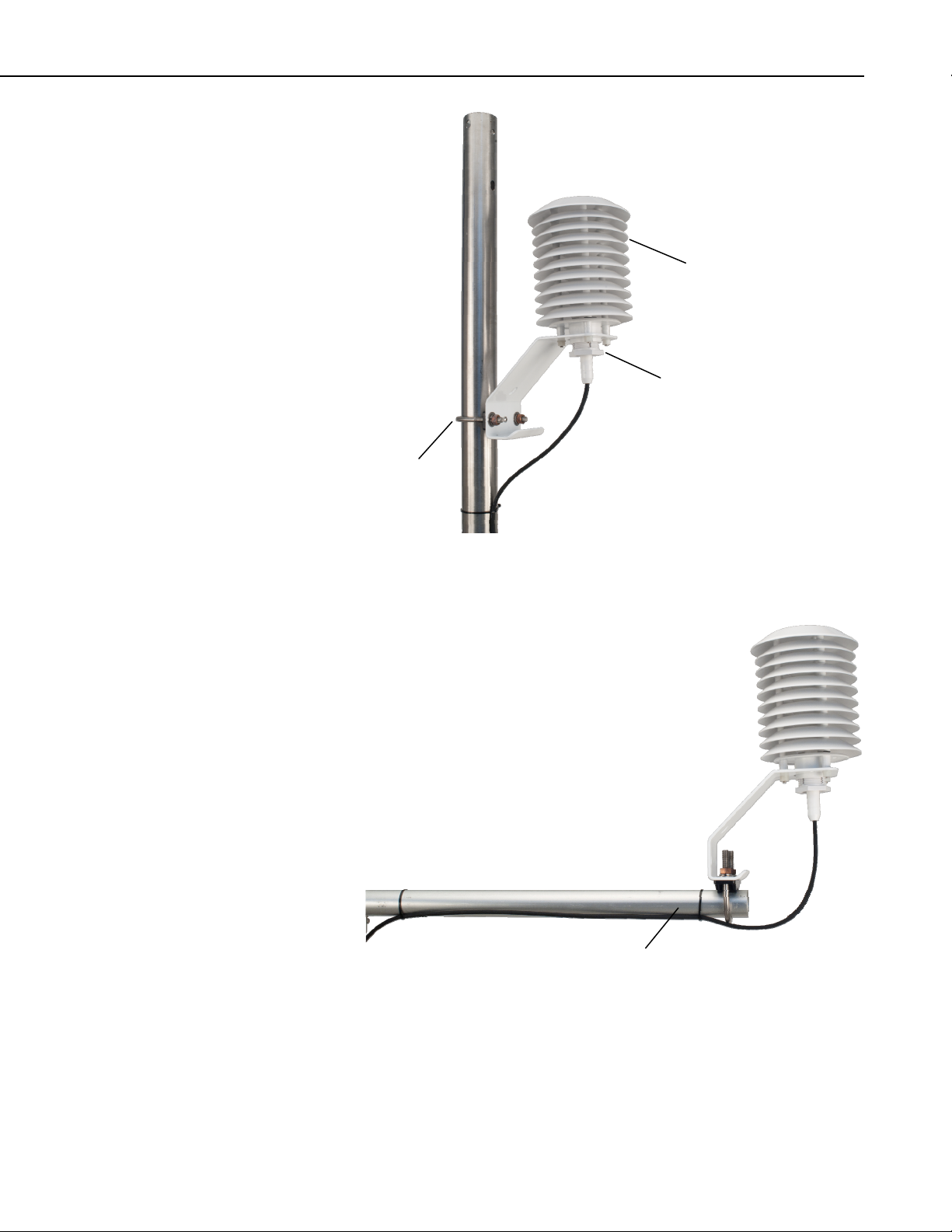
2. Attach the radiation shield to the tripod mast, crossarm, or tower leg using
the supplied U-bolt. See FIGURE 4-1 and FIGURE 4-2 for examples of
shield mounting.
3. Insert the probe into the radiation shield leaving about 2.5 cm (1 in.)
exposed below the hex plug.
4. Tighten the hex plug such that it compresses against the body of the
HC2S3 to hold it inside the radiation shield.
5. Attach the probe to the cable by aligning the keyed connectors, pushing
the connectors together and tightening the knurled ring.
6. Route the cable to the datalogger, and secure the cable to the mounting
structure using cable ties.
2
Page 9
U-bolt
Model HC2S3 Temperature and Relative Humidity Probe
41003-5
PN 27731 Hex Plug
FIGURE 4-1. HC2S3 and 41003-5 Radiation Shield on a tripod mast
CM200 Series Crossarm
FIGURE 4-2. HC2S3 and 41003-5 Radiation Shield on a CM200 Series
Crossarm
3
Page 10
Model HC2S3 Temperature and Relative Humidity Probe
4.2 Step 2 — Use SCWin Short Cut to Program Datalogger and Generate Wiring Diagram
The simplest method for programming the datalogger to measure the HC2S3 is
to use Campbell Scientific's SCWin Short Cut Program Generator.
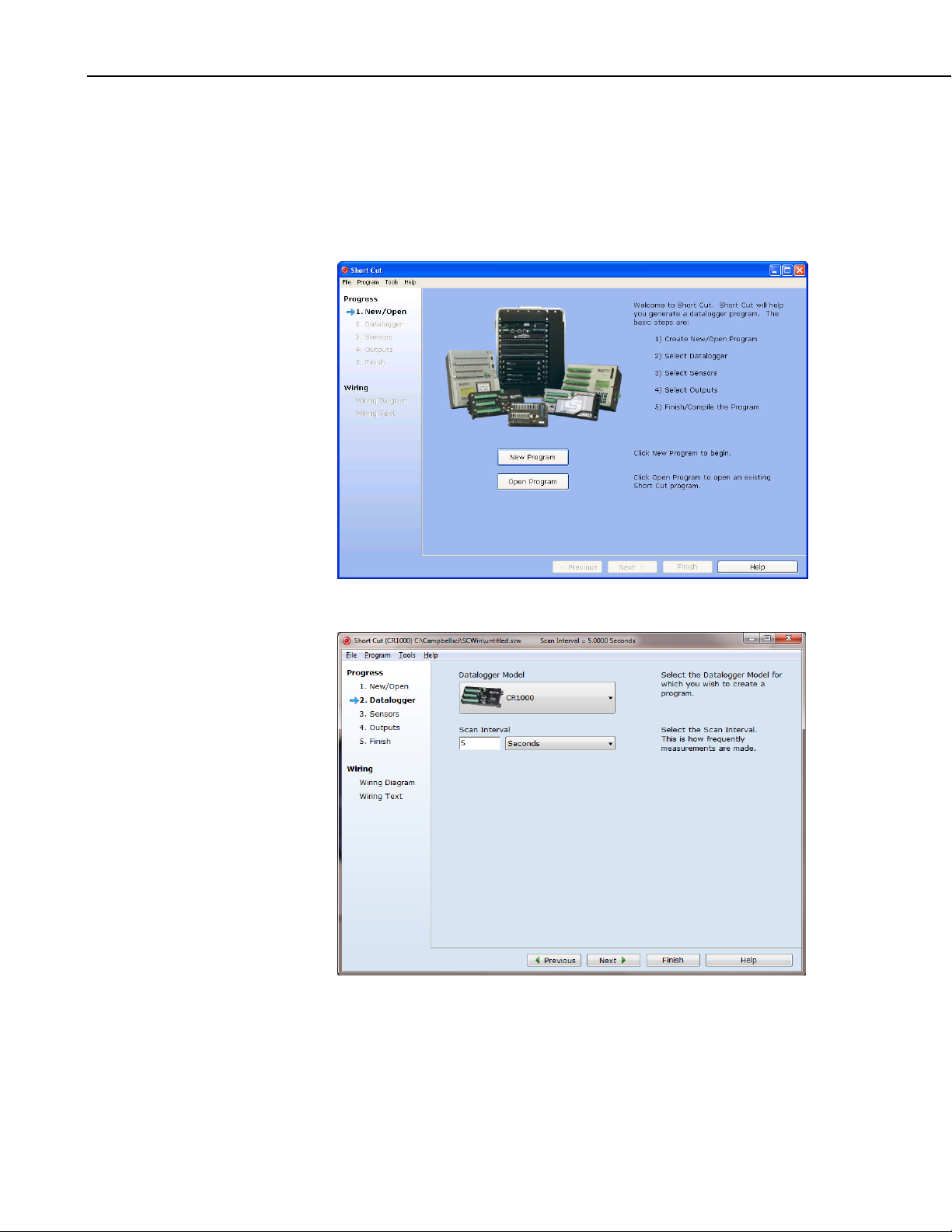
1. Open Short Cut and click on New Program.
2. Select a datalogger and scan interval.
4
Page 11
Model HC2S3 Temperature and Relative Humidity Probe
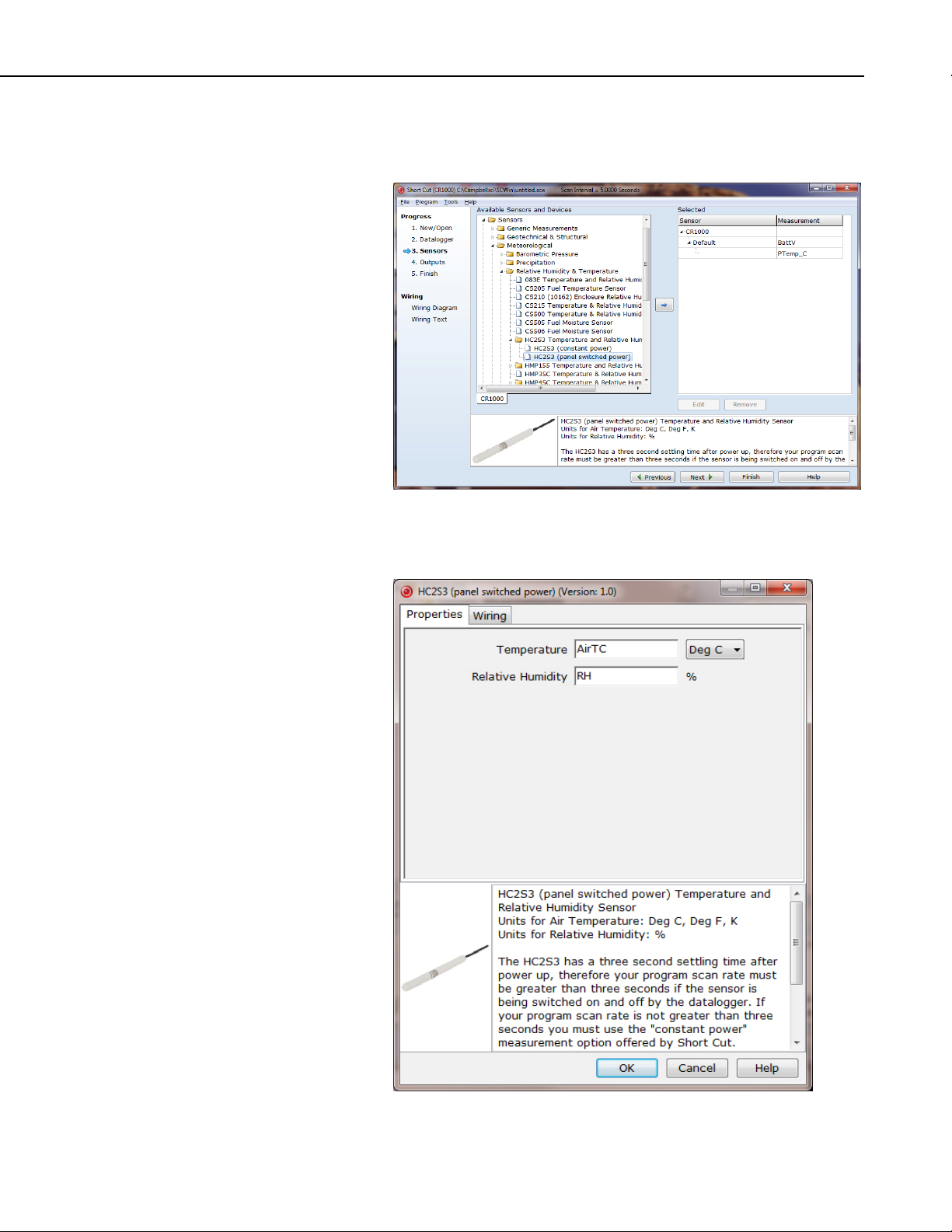
3. Select HC2S3 Temperature and Relative Humidity Sensor and choose
either constant power or panel switched power (uses less current), then
click the right arrow to add it to the list of sensors to be measured.
4. Define the name of the public variables. Variables default to AirTC and
RH that hold the air temperature and relative humidity measurements.
Select the desired units of measure. Units default to Deg C.
5
Page 12
Model HC2S3 Temperature and Relative Humidity Probe
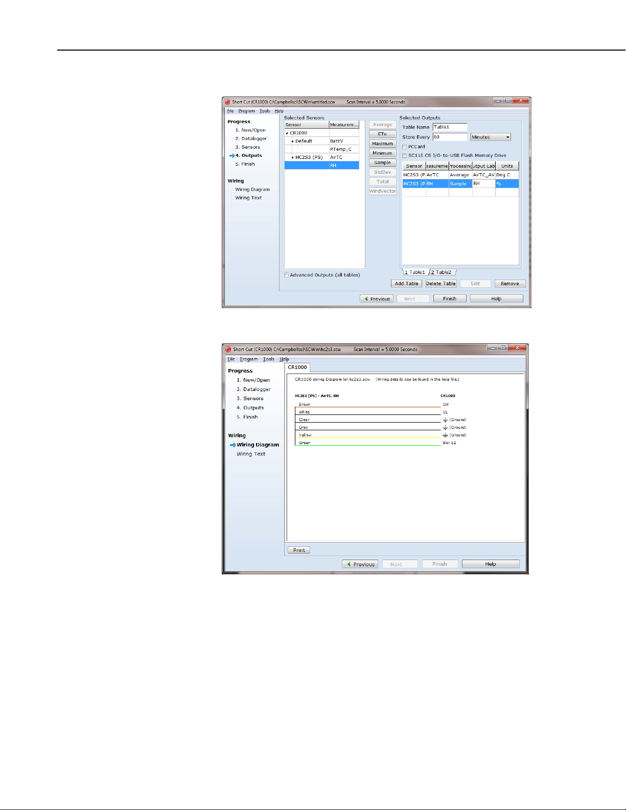
5. Choose the outputs for the AirTC and RH and then select finish.
6. Wire according to the wiring diagram generated by SCWin Short Cut.
6
Page 13
5. Overview
Model HC2S3 Temperature and Relative Humidity Probe
The HC2S3 is a digital probe with 0 to 1 V linear output signals for
temperature and humidity, and a UART serial interface. The voltage signals
can be measured with two single-ended or two differential inputs on the
datalogger. A special Rotronic cable and the SDM-SIO1 Serial I/O Module or
MD485 RS-485 Interface is required to interface with the UART as described
in Appendix B.
The D/A converter used to generate the analog output signals has 16-bit
resolution. The default configuration is for temperature -40° to +60°C, and
0 - 100% relative humidity. Temperature range and other default settings can
be changed as described in Appendix A.
A cable ordered through Campbell Scientific for the HC2S3 includes an
internal voltage regulator that applies 3.3 V to the probe from a 5 to 24 V
power source. 12V power is recommended for use with Campbell Scientific
dataloggers. Where minimizing power use is important, power can be
switched on and off for the measurement provided there is a three-second
warm-up delay. Switching power avoids the constant current flow through
datalogger ground, which can affect the accuracy of low level single-ended
voltage measurements, primarily with older dataloggers such as the 21X.
Probes are polarity protected by the keyed connector and a diode in the
connector interface provided with the Campbell Scientific cable.
Campbell Scientific offers two filters:
Polyethylene filter: Default filter, protection against fine dust
particles, no water absorption or retention, good response time.
Teflon filter: Recommended for marine environments, slower
response time than the polyethylene filter, ordered separately.
Campbell Scientific offers the HC2S3-L and HC2S3-QD. The HC2S3-L has a
user-supplied cable length and several cable termination options. When the
HC2S3-L is ordered, enter the cable length, in feet, after the –L; for example,
HC2S3-L11 for a probe with an 11 foot cable. TABLE 5-1 gives the
recommended lengths for various mounts.
TABLE 5-1. Recommended Lead Lengths
2 m Height Atop a tripod or tower via a 2 ft crossarm such as the CM202
Mast/Leg CM202 CM6 CM10 CM110 CM115 CM120 UT10 UT20 UT30
9' 11' 11' 14' 14' 19' 24' 14' 24' 37'
Note: Add two feet to the cable length if you are mounting the enclosure on the leg base of a CM106 or CM110
series tripod.
7
Page 14

Model HC2S3 Temperature and Relative Humidity Probe
The HC2S3-L's cable can terminate in:
• Pigtails that connect directly to a Campbell Scientific datalogger
(cable termination option –PT; see Section 4).
• Connector that attaches to a prewired enclosure (cable termination
option –PW).
• Connector that attaches to a CWS900 Wireless Sensor Interface (cable
termination option –CWS). The CWS900 enables the probe to be used
in a wireless sensor network.
• Connector that attaches to the Temp/RH connector on a CS110
Electric Field Meter or ET-series weather station (cable termination
option –C).
• Military-style connector that attaches to the Temp/RH connector on a
RAWS-P Permanent Remote Automated Weather Station (cable
termination option –RQ).
The HC2S3-QD is included with the RAWS-F Quick Deployment Remote
Automated Weather Station and can be ordered as a replacement part. Its cable
has a 65-in. length and terminates in a military-style connector that attaches to
the Temp/RH connector on the RAWS-F connector panel.
6. Specifications
Features:
• Well-suited for long-term, unattended applications
• Accurate and rugged
• Compatible with all Campbell Scientific dataloggers (including the
CR200(X) series)
Compatibility: CR200(X) series
CR800 series
CR1000
CR3000
CR5000
CR9000(X)
CR7X
CR510
CR10(X)
CR23X
21X
Operating Limits at Electronics: -40° to +100°C
Storage Temperature: -50° to +100°C
Probe Length: 85 mm (3.3 in.), 183 mm (7.25 in.)
including connector
Probe Diameter: 15 mm (0.6 in.)
8
Probe Weight: 10 g (0.35 oz)
Filter: Polyethylene or Teflon (optional,
ordered separately)
Page 15

Power Consumption: <4.3 mA @ 5 V
<2.0 mA @ 12 V
Supply Voltage (using CSI cable): 5 to 24 Vdc (12 Vdc recommended)
Start-up time: 1.5 s typical (Rotronic specification,
Campbell Scientific recommends 2 s at
60°C, 3 s at 0°C, 4 s at -40°C)
Maximum Startup Current: <50 mA during 2 µs
Maximum Lead Length: 300 m (1000 ft) with 12 V power, 3 m
(10 ft) with 5 V power
Analog outputs
Offset at 0 V: ±3 mV (maximum)
Deviation from Digital Signal: < ±1 mV (0.1°C, 0.1% RH)
6.1 Temperature Sensor
Sensor: PT100 RTD, IEC 751 1/3 Class B, with
calibrated signal conditioning
Temperature Measurement Range: -50° to +100°C (default -40° to + 60°C)
Model HC2S3 Temperature and Relative Humidity Probe
Temperature Output Signal Range: 0 to 1.0 V
Accuracy at 23°C: ±0.1°C with standard configuration
settings
Long Term Stability: <0.1°C/year
Sensor Time Constant (63% step
change (1 m/s air flow at sensor)): ≤22 s with PE filter, ≤30 s with Teflon
filter
Temperature Accuracy over Temperature:
9
Page 16
Model HC2S3 Temperature and Relative Humidity Probe
6.2 Relative Humidity Sensor
Sensor: ROTRONIC Hygromer® IN1
Relative Humidity
Measurement Range: 0 to 100% non-condensing
RH Output Signal Range: 0 to 1 Vdc
Accuracy at 23°C: ±0.8% RH with standard configuration
settings
Typical Long Term Stability: <1% RH per year
Sensor Time Constant (63% of a
35 to 80% RH step change
(1 m/s air flow at sensor)): ≤22 s with PE filter, ≤30 s with Teflon
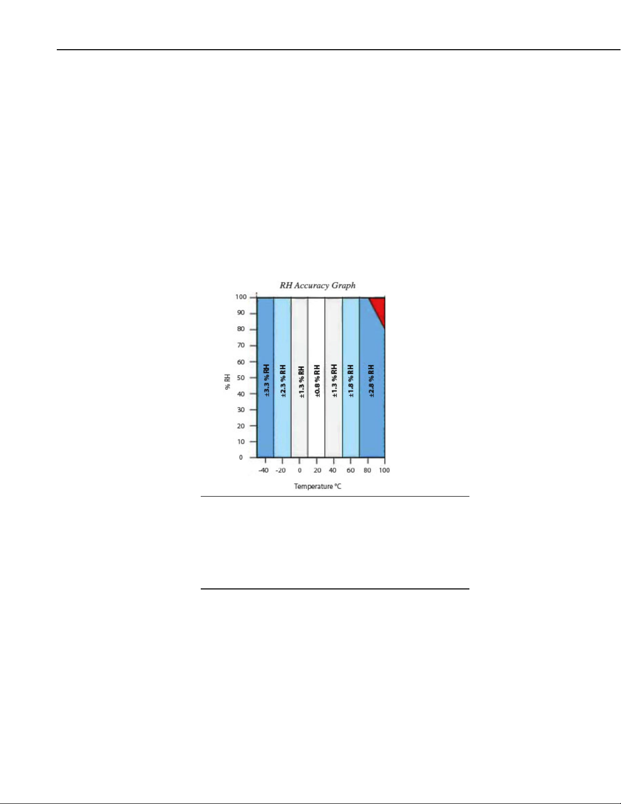
RH Accuracy over Temperature:
filter
10
CAUTION
The black outer jacket of the cable is Santoprene
This compound was chosen for its resistance to
temperature extremes, moisture, and UV degradation.
However, this jacket will support combustion in air. It is
rated as slow burning when tested according to U.L. 94
H.B. and will pass FMVSS302. Local fire codes may
preclude its use inside buildings.
6.3 Default Settings and Digital Interface
Please refer to Appendices.
®
rubber.
Page 17

7. Installation
7.1 Siting
7.2 Assembly and Mounting
Model HC2S3 Temperature and Relative Humidity Probe
Sensors should be located over an open level area at least 9 m (EPA) in
diameter. The surface should be covered by short grass, or where grass does
not grow, the natural earth surface. Sensors should be located at a distance of
at least four times the height of any nearby obstruction, and at least 30 m
(EPA) from large paved areas. Sensors should be housed in a suitable radiation
shield.
Standard measurement heights:
1.5 m (AASC)
1.25 to 2.0 m (WMO)
2.0 m (EPA)
See Section 10, References for a list of references that discuss temperature and
relative humidity sensors.
7.3 Wiring
Tools Required:
• 1/2 in. open end wrench
• small screw driver provided with datalogger
• UV resistant cable ties
• small pair of diagonal-cutting pliers
The HC2S3 probe and its calibration card are shipped in a small box, with the
box and PN 27731 Hex Plug attached to the cable. PN 27731 is used to mount
the probe inside the 41003-5 Radiation Shield as described in Section 4,
Quickstart.
Attach the probe to the cable by aligning the keyed connectors, pushing the
connectors together and tightening the knurled ring.
When exposed to solar radiation the probe must be housed in a radiation shield
such as the 41003-5 naturally aspirated shield, or the 43502 motor aspiration
shield (please refer to the 43502 product manual for details). The 41003-5
Radiation Shield has a U-bolt for attaching the shield to a tripod mast/tower leg
or CM200 series crossarm (shown in FIGURE 4-1 and FIGURE 4-2 in the
Quickstart section).
Connections to Campbell Scientific dataloggers for measuring humidity and
temperature using two single-ended or two differential analog inputs are given
in TABLE 7-1 and TABLE 7-2. Use a single-ended analog measurement when
the cable length is less than 6.1 m (20 ft), or if power is switched off between
measurements. For cable lengths longer than 6.1 m or when the probe is
continuously powered, use a differential analog measurement. See Section 7.5
for a discussion on errors caused by long cable lengths.
11
Page 18

Model HC2S3 Temperature and Relative Humidity Probe
The HC2S3 draws approximately 2 mA powered from 12V. The HC2S3 can
be continuously powered from the 12V terminal, or power can be switched
with the SW12V terminal to conserve battery life. When power is switched, a
three-second warm-up time is required. Using the SW12V terminal on the
CR10X datalogger requires a user-supplied jumper wire connected between the
SW 12V CTRL terminal and a Control Port (C1 to C8).
CAUTION
When measuring the HC2S3 with single-ended
measurements, the yellow and gray leads must both be
connected to AG on the CR10(X) and CR500/CR510 or to
on the CR1000, CR5000, and CR23X. Doing otherwise
will connect the datalogger’s analog and power ground
planes to each other, which in some cases can cause
offsets on low-level analog measurements. To avoid 2 mA
flowing into analog ground, switch power on/off for its
measurement.
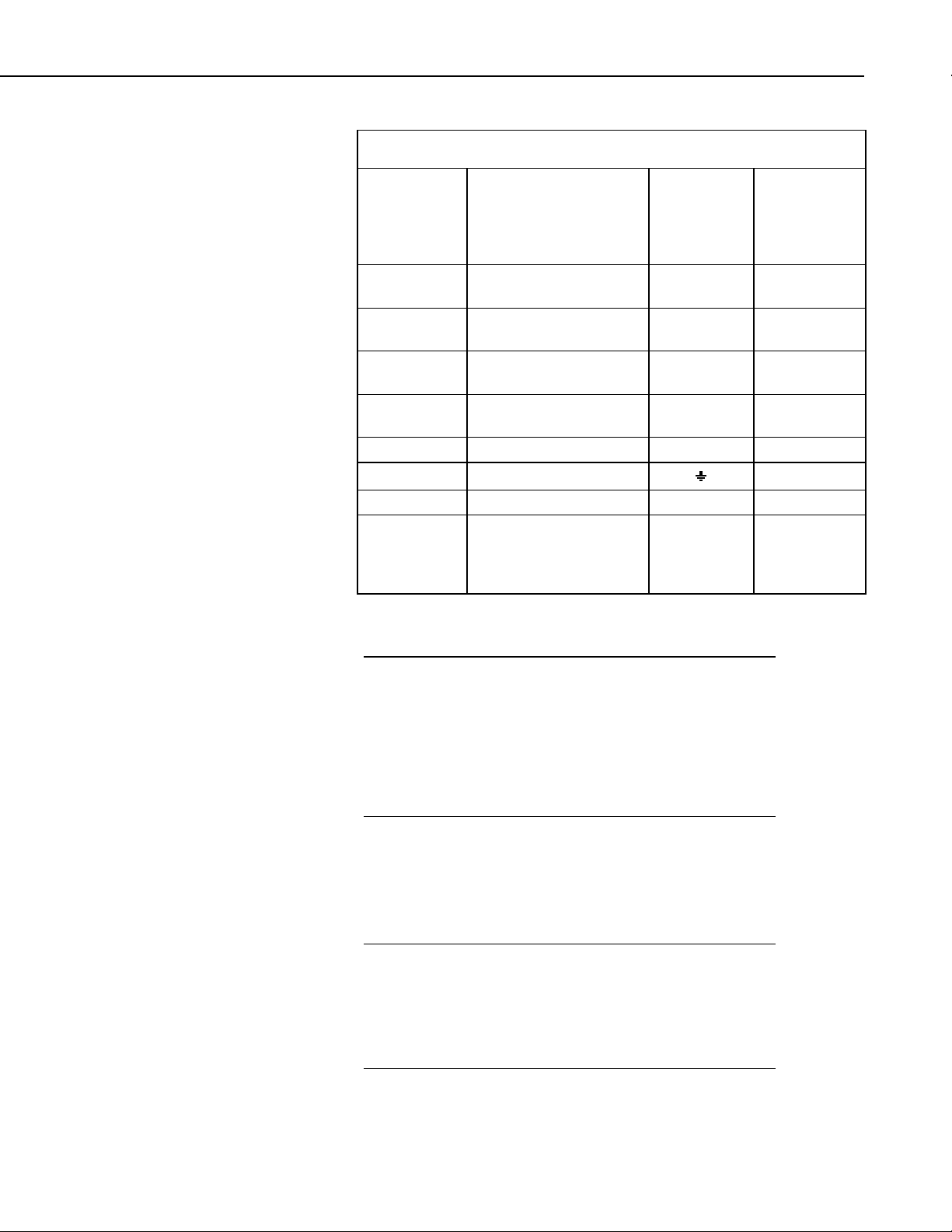
TABLE 7-1. Connections for Single-Ended Measurements
Color
Brown Temperature
White Relative Humidity
Yellow Signal Reference
Gray Power Ground
Clear Shield
Description
Signal
Signal
CR1000,
CR3000,
CR800,
CR5000,
CR23X
Single-Ended
Input
Single-Ended
Input
CR10X
CR10,
CR510,
CR500
Single-Ended
Input
Single-Ended
Input
AG
AG
G
Green Power 12V/*SW12V 12V/*SW12V
12
*CR10X Power Control if
using SW 12V
Jumper from
SW 12V
CTRL to
Control Port
Page 19
Model HC2S3 Temperature and Relative Humidity Probe
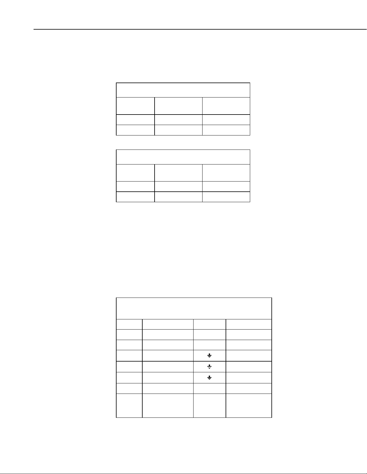
TABLE 7-2. Connections for Differential Measurements
Color
Brown
Jumper to
Yellow
White Relative Humidity Signal
Yellow Signal Reference
Gray Power Ground G G
Clear Shield
Green Power 12V/*SW12V 12V/*SW12V
Temperature Signal
*CR10X Power Control if
Description
Temperature
Signal
Reference
using SW 12V
CR1000,
CR3000,
CR800,
CR5000,
CR23X
Differential
Input – H
Differential
Input – L
Differential
Input – H
Differential
Input – L
CR10X
CR10,
CR510,
CR500
Differential
Input – H
Differential
Input – L
Differential
Input – H
Differential
Input – L
G
Jumper from
SW 12V
CTRL to
Control Port
7.4 Programming
NOTE
NOTE
This section is for users who write their own datalogger
programs. You do not need to read this section if using our Short
Cut Program Generator, or connecting the probe to a prewired
enclosure, RAWS-P station, RAWS-F station, or CWS900
Wireless Sensor Interface. Our prewired enclosures, RAWS-P
stations, and RAWS-F stations include a datalogger program.
Refer to the Wireless Sensor Manual for programming
information if using the probe with a CWS900.
The temperature and relative humidity signals from the HC2S3 are measured
using either single-ended voltage instructions (VoltSE() in CRBasic or
Instruction 1 in Edlog) or differential voltage instructions (VoltDiff() in
CRBasic or Instruction 2 in Edlog). Differential measurements are
recommended for cables longer than 6.0 m (20 ft) as discussed in Section 7.5.
When the probe is connected to a CS110 Electric Field Meter,
the probe is measured by the CS110's internal CR1000
datalogger module using VoltSE() instructions. Relative
humidity and temperature signals are measured on single-ended
channels 1 and 2, respectively. The 250 µs integration should be
used in the VoltSE() instructions.
13
Page 20
Model HC2S3 Temperature and Relative Humidity Probe
The HC2S3 output scale is 0 to 1000 mV for the temperature range of
-40° to +60°C and 0 to 1000 mV for the relative humidity range of 0 to 100%.
Multipliers and Offsets for the measurement instructions to convert the
measurement result (mV) to temperature and relative humidity are shown in
TABLE 7-3 and TABLE 7-4.
TABLE 7-3. Temperature
Units
Multiplier
(degrees mV
-1
)
Offset
(degrees)
Celsius 0.1 -40
Fahrenheit 0.18 -40
TABLE 7-4. Humidity
Units
Multiplier
(% mV
-1
)
Offset
(%)
Percent 0.1 0
Fraction 0.001 0
7.4.1 Example Programs using Single-Ended Measurement Instructions
The example programs for the CR1000 and CR10X use the SW12V terminal to
switch power to the probe, delay for 3 seconds and measure the output voltages
using single-ended measurement instructions.
Relative humidity and temperature (deg C) are measured on single-ended input
channels 1 and 2 respectively. The program sets relative humidity equal to 100
if the measured value is greater than 100 but less than 103%. Values greater
than 103% are not set equal to 100, and indicate a problem with the sensor or
its calibration.
14
TABLE 7-5. Wiring for Single-ended
Measurement Examples
Color Description CR1000 CR10(X)
Brown Temperature SE 2 SE 2
White Relative Humidity SE 1 SE 1
Yellow Signal Reference
Gray Power Ground
Clear Shield
AG
AG
G
Green Power SW12V SW12V
Jumper from
SW 12V CTRL
to Control Port
Page 21

Model HC2S3 Temperature and Relative Humidity Probe
CR1000 program using single-ended measurements
'CR1000 program to measure HC2S3 with single-ended inputs
Public AirTC
Public RH
Units AirTC=Deg C
Units RH=%
DataTable(Table1,True,-1)
DataInterval(0,60,Min,10)
Average(1,AirTC,FP2,False)
Sample(1,RH,FP2)
EndTable
BeginProg
Scan(5,Sec,1,0)
PortSet(9,1) 'Turn on switched 12V
Delay(0,3,Sec) '3-second delay
'HC2S3 Temperature & Relative Humidity Sensor measurements AirTC and RH:
VoltSE(RH,1,mV2500,1,0,0,_60Hz,0.1,0)
VoltSe(AirTC,1,mV2500,2,0,0,_60Hz,0.1,-40)
PortSet(9,0) 'Turn off switched 12V
If RH>100 AND RH<103 Then RH=100
CallTable(Table1)
NextScan
EndProg
CR10(X) program using single-ended measurement instructions
;{CR10X} program to measure HC2S3 with single-ended inputs
*Table 1 Program
01: 5.0000 Execution Interval (seconds)
1: Do (P86) ;Turn on switched 12V
1: 41 Set Port 1 High ;Jumper from C1 to SW 12V CTRL
2: Excitation with Delay (P22) ;3-second delay
1: 1 Ex Channel
2: 0 Delay W/Ex (0.01 sec units)
3: 300 Delay After Ex (0.01 sec units)
4: 0 mV Excitation
;HC2S3 Temperature & Relative Humidity Sensor measurements AirTC and RH:
3: Volt (SE) (P1)
1: 1 Reps
2: 25 2500 mV 60 Hz Rejection Range
3: 2 SE Channel
4: 2 Loc [ AirTC ]
5: 0.1 Multiplier
6: -40.0 Offset
15
Page 22

Model HC2S3 Temperature and Relative Humidity Probe
4: Volt (SE) (P1)
1: 1 Reps
2: 25 2500 mV 60 Hz Rejection Range
3: 4 SE Channel
4: 1 Loc [ RH ]
5: 0.1 Multiplier
6: 0 Offset
5: Do (P86) ;Turn off switched 12V
1: 51 Set Port 1 Low
6: If (X<=>F) (P89)
1: 1 X Loc [ RH ]
2: 3 >=
3: 100 F
4: 30 Then Do
7: If (X<=>F) (P89)
1: 1 X Loc [ RH ]
2: 4 <
3: 103 F
4: 30 Then Do
8: Z=F x 10^n (P30)
1: 100 F
2: 0 n, Exponent of 10
3: 1 Z Loc [ RH ]
9: End (P95)
10: End (P95)
11: If time is (P92)
1: 0 Minutes (Seconds --) into a
2: 60 Interval (same units as above)
3: 10 Set Output Flag High (Flag 0)
12: Set Active Storage Area (P80)
1: 1 Final Storage Area 1
2: 101 Array ID
13: Real Time (P77)
1: 1220 Year,Day,Hour/Minute (midnight = 2400)
14: Average (P71)
1: 1 Reps
2: 2 Loc [ AirTC ]
15: Sample (P70)
1: 1 Reps
2: 1 Loc [ RH ]
16
Page 23

Model HC2S3 Temperature and Relative Humidity Probe
CR1000 program using single-ended measurements in Slow Sequence scan
The following program example has a 1-second main scan, and uses a Slow Sequence scan to
measure the HC2S3 every 5 seconds. Every 5 seconds the program switches power to the HC2S3 on
the SW-12 terminal, delays for a 3-second “warm-up”, and measures relative humidity and
temperature on single-ended channels 1 and 2 respectively. Because of the 3-second delay, the
program must be run in SequentialMode. Please contact Campbell Scientific if your program must
run in pipeline mode.
'CR1000 program
SequentialMode 'Required for Slow Sequence scan
Public AirTC
Public RH
Public Battery_volts
Public Ptemp
Units AirTC = C
Units RH = %
Units Batter_volts = V
Units Ptemp = C
DataTable (Table1,True,-1)
DataInterval (0,60,Min,10)
Average (1,Battery_volts,FP2,FALSE)
Average (1,Ptemp,FP2,FALSE)
Average (1,AirTC,FP2,FALSE)
Sample 1,RH,FP2)
EndTable
BeginProg
Scan (1,Sec,1,0) 'Run main scan 1 second
Battery (Battery_volts)
PanelTemp (Ptemp_C,250)
'add additional instructions to be executed every 1 second
CallTable (Table1)
NextScan
SlowSequence
Scan (5,Sec,0,0) 'Run slow sequence scan every 5 seconds
PortSet (9,TRUE) 'Turn on HC2S3
Delay (0,3000,mSec) 'Wait 3 seconds for HC2S3 to warmup
VoltSe (AirTC,1,mV2500,2,0,0,_60Hz,0.1,-40) 'Measure HC2S3 temperature
VoltSe (RH,1,mV2500,1,0,0,_60Hz,0.1,0) 'Measure HC2S3 relative humidity
PortSet (9,FALSE) 'Turn off probe
NextScan
EndProg
7.4.2 Example Programs using Differential Measurement Instructions
Temperature and humidity are measured on differential input channels 1 and 2
respectively. The program sets relative humidity equal to 100 if the measured
value is greater than 100 but less than 103%. Values greater than 103% are not
set equal to 100, and indicate a problem with the sensor or its calibration.
17
Page 24
Model HC2S3 Temperature and Relative Humidity Probe
TABLE 7-6. Wiring for
Differential Measurement Examples
Color Description CR1000 CR10(X)
Brown Temperature 1H 1H
Jumper to
Yellow
Temperature Signal
Reference
White Relative Humidity 2H 2H
Yellow Signal Reference 2L 2L
Gray Power Ground G G
Clear Shield
Green Power 12V 12V
CR1000 program using differential measurements
'CR1000 program to measure HC2S3 with differential measurements
Public AirTC
Public RH
DataTable(Temp_RH,True,-1)
DataInterval(0,60,Min,0)
Average(1,AirTC,IEEE4,0)
Sample(1,RH,IEEE4)
EndTable
BeginProg
Scan(1,Sec,1,0)
'HC2S3 Temperature & Relative Humidity Sensor measurements AirTC and RH:
VoltDiff (AirTC,1,mV2500,1,True,0,_60Hz,0.1,-40)
VoltDiff (RH,1,mV2500,2,True,0,_60Hz,0.1,0)
If RH>100 And RH<103 Then RH=100
CallTable(Temp_RH)
NextScan
EndProg
1L 1L
G
18
CR10(X) program using differential measurement instructions
;{CR10X}
*Table 1 Program
01: 1.0000 Execution Interval (seconds)
;HC2S3 Temperature & Relative Humidity Sensor measurements AirTC and RH:
1: Volt (Diff) (P2)
1: 1 Reps
2: 25 2500 mV 60 Hz Rejection Range
3: 1 DIFF Channel
4: 3 Loc [ AirTC ]
5: 0.1 Multiplier
6: -40 Offset
Page 25

Model HC2S3 Temperature and Relative Humidity Probe
2: Volt (Diff) (P2)
1: 1 Reps
2: 25 2500 mV 60 Hz Rejection Range
3: 2 DIFF Channel
4: 4 Loc [ RH ]
5: 0.1 Multiplier
6: 0 Offset
3: If (X<=>F) (P89)
1: 4 X Loc [ RH ]
2: 3 >=
3: 100 F
4: 30 Then Do
4: If (X<=>F) (P89)
1: 4 X Loc [ RH ]
2: 4 <
3: 103 F
4: 30 Then Do
5: Z=F x 10^n (P30)
1: 100 F
2: 0 n, Exponent of 10
3: 4 Z Loc [ RH ]
6: End (P95)
7: End (P95)
8: If time is (P92)
1: 0 Minutes (Seconds --) into a
2: 60 Interval (same units as above)
3: 10 Set Output Flag High (Flag 0)
9: Set Active Storage Area (P80)
1: 1 Final Storage Area 1
2: 101 Array ID
10: Real Time (P77)
1: 1220 Year,Day,Hour/Minute (midnight = 2400)
11: Average (P71)
1: 1 Reps
2: 3 Loc [ AirTC ]
12: Sample (P70)
1: 1 Reps
2: 4 Loc [ RH ]
7.5 Measuring Probes with Long Cables
For cable lengths longer than 6.1 m (20 ft), Campbell Scientific recommends
measuring the voltage signals using differential inputs as discussed below.
Connections for differential inputs are given in TABLE 7-2.
19
Page 26

Model HC2S3 Temperature and Relative Humidity Probe
The signal reference (yellow) and the power ground (gray) are in common
inside the HC2S3. When the HC2S3 temperature and relative humidity are
measured using a single-ended analog measurement, both the signal reference
and power ground are connected to ground at the datalogger. The signal
reference and power ground both serve as the return path for power. There will
be a voltage drop along those leads because the wire itself has resistance.
The HC2S3 draws approximately 2 mA when powered with 12 V. The wire
used in the HC2S3 (P/N 27746) has resistance of 14.74 Ω/304.8 m (1000 ft).
Since the signal reference and the power ground are both connected to ground
at the datalogger, the effective resistance of those wires together is half of
14.74 Ω/304.8 m (1000 ft), or 7.37 Ω/304.8 m (1000 ft). Using Ohm’s law, the
voltage drop (V
), along the signal reference/power ground, is given by Eq. (1).
d
V
d
∗= RI
Ω∗=
)' (1000 m 304.8 .377 mA 2
(1)
This voltage drop will raise the apparent temperature and relative humidity
because the difference between the signal and signal reference lead, at the
datalogger, has increased by V
relative humidity is 0.15°C and 0.15% per 30.5 m (100 ft) of cable length,
respectively (assuming a temperature range of -40° to +60°C). When there are
not enough inputs available on the datalogger to allow for differential
measurements, single-ended measurements can be made and the errors
associated with cable length subtracted as offsets.
8. Sensor Maintenance
Corroded, discolored or clogged filters should be replaced. To replace the
filter, unscrew the filter from the probe and pull it straight away, being careful
not to bend or damage the sensors. Before putting on the replacement filter
check the alignment of the sensors with the probe, and if necessary, carefully
correct the alignment before installing the filter.
The Teflon filter tip is recommended when the sensor is installed in close
proximity to the ocean or other bodies of salt water. A coating of salt (mostly
NaCl) may build up on the radiation shield, sensor, filter and even the sensors.
A buildup of salt on the filter or sensors will delay or destroy the response to
atmospheric humidity.
=
. The approximate error in temperature and
d
)' (1000 m 304.8 mV 4.71
20
Long term exposure of the relative humidity sensor to certain chemicals and
gases may affect the characteristics of the sensor and shorten its life. The
resistance of the sensor depends strongly on the temperature and humidity
conditions and the length of the pollutant influence.
In general, the HC2S3 requires minimal maintenance. The radiation shield
should be kept clean and free of debris, and the sensor should be calibrated
annually. Please obtain an RMA number before returning the HC2S3 to
Campbell Scientific for calibration. Please refer to Warranty and Assistance
sections at the beginning of the manual.
Page 27

9. Troubleshooting
Symptom: -9999, NAN, -40°C, or 0 % relative humidity
1. Check that the sensor is wired to the correct analog input channels as
specified by the measurement instructions.
2. Verify the voltage range code for the single-ended or differential
measurement instruction is correct for the datalogger type.
3. Verify the green power wire is connected to the 12V, SW12V, or 5V
terminal. When SW12V is used with a CR10X datalogger, verify the
SW 12V CTRL is jumpered to the Control Port specified in the program.
Cables longer than 3 m (10 ft) should be powered by the 12V, rather than
the 5V terminal.
A voltmeter can be used to check the output voltage for temperature and
relative humidity on the brown and white wires respectively (temperature
°C = mV * 0.1 – 40.0; relative humidity % = mV * 0.1).
Symptom: Incorrect temperature or relative humidity
Model HC2S3 Temperature and Relative Humidity Probe
10. References
1. Verify the multiplier and offset parameters are correct for the desired units
(TABLE 7-3) and temperature range.
2. Default settings are listed in Appendix A, which include the setting “Limit
humidity output to 100%”. This setting is “disabled” for probes
purchased through Campbell Scientific. Accuracy of the humidity
measurement over temperature is shown in the graph in Section 6.2. For
example, at -20°C the accuracy is ±2.3%, so a reading of 102.3% at 100%
humidity is within the accuracy specification. Programs created by Short
Cut set humidity values greater than 100% and less than 103% to 100%.
Humidity values greater than 103% are left unchanged to indicate a
problem with the probe or measurement.
AASC, 1985: The State Climatologist (1985) Publication of the American
Association of State Climatologists: Heights and Exposure Standards for
Sensors on Automated Weather Stations, v. 9, No. 4 October, 1985.
(www.stateclimate.org/publications/state-climatologist/NOAA-NCYSCBOOKS-SC77097/00000029.pdf)
EPA, 2000: Meteorological Monitoring Guidance for Regulatory Modeling
Applications, EPA-454/R-99-005. Office of Air Quality Planning and
Standards, Research Triangle Park, North Carolina 27711.
EPA, 2008: Quality Assurance Handbook for Air Pollution Measurement
Systems, Vol. IV, Meteorological Measurements, Ver. 2.0, EPA-454/B-08002 (revised 2008). Office of Air Quality Planning and Standards,
Research Triangle Park, NC 27711.
Goff, J. A. and S. Gratch, 1946: Low-pressure properties of water from -160°
to 212°F, Trans. Amer. Soc. Heat. Vent. Eng., 51, 125-164.
21
Page 28

Model HC2S3 Temperature and Relative Humidity Probe
Lowe, P. R., 1977: An approximating polynomial for the computation of
saturation vapor pressure, J. Appl. Meteor., 16, 100-103.
Meyer, S. J. and K. G. Hubbard, 1992: Nonfederal Automated Weather
Stations and Networks in the United States and Canada: A Preliminary
Survey, Bulletin Am. Meteor. Soc., 73, No. 4, 449-457.
Weiss, A., 1977: Algorithms for the calculation of moist air properties on a
hand calculator, Amer. Soc. Ag. Eng., 20, 1133-1136.
WMO, 2008. Guide to Meteorological Instruments and Methods of
Observation. World Meteorological Organization No. 8, 7th edition,
Geneva, Switzerland.
22
Page 29

Appendix A. Absolute Humidity
The HC2S3 measures the relative humidity. Relative humidity is defined by
the equation below:
e
RH
100
∗= (A-1)
e
s
where RH is the relative humidity, e is the vapor pressure in kPa , and e
saturation vapor pressure in kPa. The vapor pressure, e, is an absolute measure
of the amount of water vapor in the air and is related to the dew point
temperature. The saturation vapor pressure is the maximum amount of water
vapor that air can hold at a given air temperature. The relationship between
dew point and vapor pressure, and air temperature and saturation vapor
pressure are given by Goff and Gratch (1946), Lowe (1977), and Weiss (1977).
Relative Humidity is relative to saturation above water, even below freezing
point. This is why these sensors should not measure 100% RH below zero
degrees C, as described in Section A.1.
When the air temperature increases, so does the saturation vapor pressure.
Conversely, a decrease in air temperature causes a corresponding decrease in
saturation vapor pressure. It follows then from Eq. (A-1) that a change in air
temperature will change the relative humidity, without causing a change
absolute humidity.
For example, for an air temperature of 20°C and a vapor pressure of 1.17 kPa,
the saturation vapor pressure is 2.34 kPa and the relative humidity is 50%. If
the air temperature is increased by 5°C and no moisture is added or removed
from the air, the saturation vapor pressure increases to 3.17 kPa and the relative
humidity decreases to 36.9%. After the increase in air temperature, there is
more energy to vaporize the water. However, the actual amount of water vapor
in the air has not changed. Thus, the amount of water vapor in the air, relative
to saturation, has decreased.
is the
s
Because of the inverse relationship between relative humidity and air
temperature, finding the mean relative humidity is often not useful. A more
useful quantity is the mean vapor pressure. The mean vapor pressure can be
computed by the datalogger program as shown in the following example.
TABLE A-1. Wiring for Vapor
Pressure Examples
Color Description CR1000
Brown Temperature SE 2
White Relative Humidity SE 1
Yellow Signal Reference
Gray Power Ground
Clear Shield
Green Power 12V
A-1
Page 30

Appendix A. Absolute Humidity
CR1000 Program that Computes Vapor Pressure and Saturation Vapor Pressure
'CR1000 program that calculates Vapor Pressure
Public AirTC
Public RH
Public RH_Frac, e_Sat, e_kPa
DataTable(Temp_RH,True,-1)
DataInterval(0,60,Min,0)
Average(1,AirTC,IEEE4,0)
Sample(1,RH,IEEE4)
Sample(1,e_kPa,IEEE4)
EndTable
BeginProg
Scan(1,Sec,1,0)
PortSet(9,1) 'Turn on switched 12V
Delay(0,3,Sec) '3-second delay
'HC2S3 Temperature & Relative Humidity Sensor measurements AirTC and RH:
VoltSE(AirTC,1,mV2500,2,0,0,_60Hz,0.1,-40.0)
VoltSE(RH,1,mV2500,1,0,0,_60Hz,0.1,0)
If RH>100 And RH<103 Then RH=100
PortSet(9,0) 'Turn off switched 12V
'Calculate Vapor Pressure
'Convert RH percent to RH Fraction
RH_Frac = RH * 0.01
'Calculate Saturation Vapor Pressure
SatVP(e_Sat, AirTC)
'Compute Vapor Pressure, RH must be a fraction
e_kPa = e_Sat * RH_Frac
CallTable(Temp_RH)
NextScan
EndProg
A.1 Measurement Below 0°C
The HC2S3 provides a humidity reading that is referenced to the saturated
water vapor pressure above liquid water, even at temperatures below 0°C,
where ice might form. This is the common way to express relative humidity
and is as defined by the World Meteorological Organization. If an RH value is
required referenced to ice, the HC2S3 readings will need to be corrected.
One consequence of using water as the reference is that the maximum humidity
that will normally be output by the sensor for temperatures below freezing is as
follows:
100%RH at 0°C 82%RH at -20°C
95%RH at -5°C 78%RH at -25°C
91%RH at -10°C 75%RH at -30°C
87%RH at -15°C
In practical terms this means that, for instance, at -20°C the air is effectively
fully saturated when the sensor outputs 82%RH.
A-2
Page 31

Appendix B. Changing the HC2S3 Settings
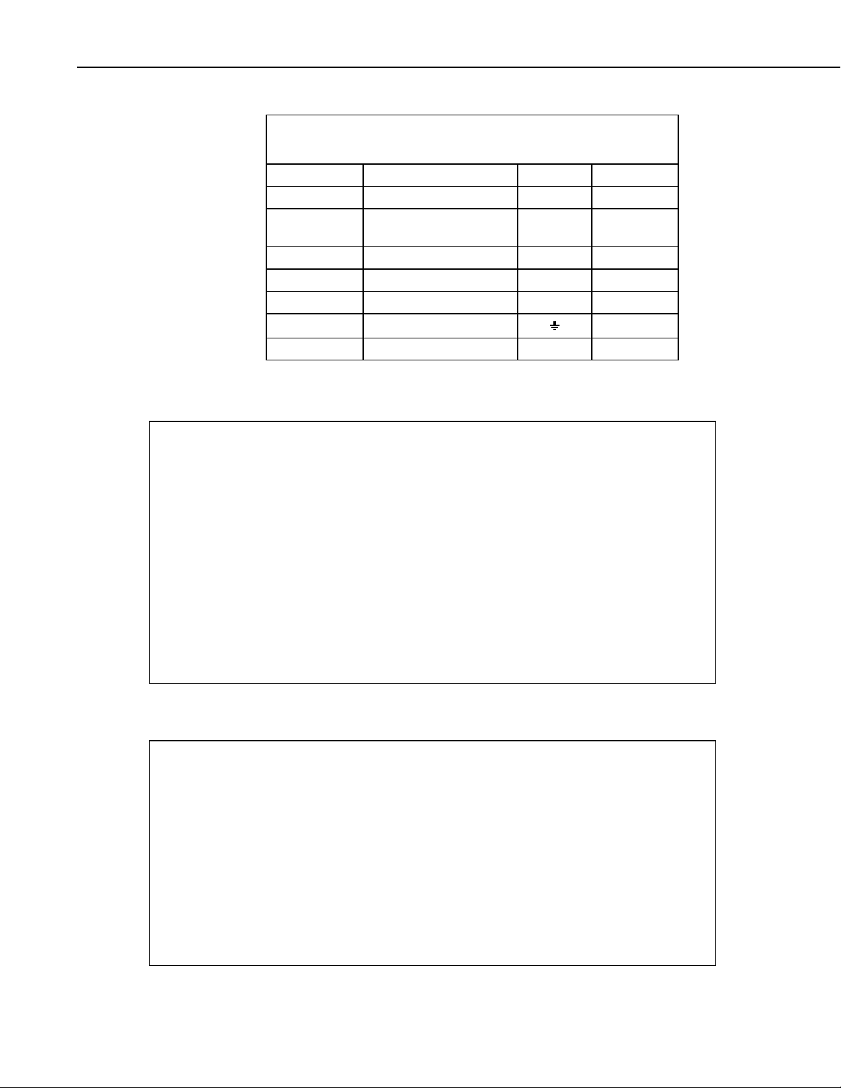
B.1 HC2S3 Default Settings
The HC2S3 probe has the following default settings, which can be changed as
described in the following sections. Additional information can be found in
Rotronic’s User Manual: E-M-HC2 Probes-VXXXX, which can be
downloaded from Rotronic's website www.rotronic-usa.com
Default Settings:
Configurable Settings Factory Default
Unit system (Metric or English) Metric
Psychrometric calculation None
Output 1 parameter, scale and unit Humidity: 0..100% RH
Output 2 parameter, scale and unit Temperature: -40...+60 deg C
Communications Protocol RO-ASCII
RS-485 Address 0
Device name Probe type
Humidity / temperature adjustment
Device write protection Disabled
Limit humidity output to 100% RH Disabled
Out-of-limit value digital alarm Disabled
Data recording Enabled (loop mode - 10 min interval)
Automatic humidity sensor test Disabled
Humidity sensor drift compensation Disabled
Fail safe mode Disabled
Simulator mode Disabled
.
Digital Interface:
Interface Type: UART (Universal Asynchronous Receiver Transmitter)
Organization: Dialog, duplex
Default Configuration:
Baud rate: 19200
Parity: none
Data bits: 8
Stop fits: 1
Flow Control: none
Logical Levels:
Logical 0: <= 0.3V*VDD
Logical 1: <= 0.8V*VDD
B-1
Page 32
Appendix B. Changing the HC2S3 Settings
B.2 Software and Hardware Requirements
For temperature (Analog Output 2), the HC2S3 default range is -40 to +60°C
for 0 to 1V. Changing the range requires Rotronic HW4 Software (Version
2.1.0 or higher), and the Rotronic model AC3001 USB adapter cable. Power to
the probe is provided by the USB port.
IMPORTANT
Prior to using the AC3001 cable, the ROTRONIC USB driver
must be installed on the PC. Both the driver and the installation
instructions (document E-M-HW4v3-Main) are located on the
HW4 CD.
B.3 Changing the Temperature Range
Install the HW4 software and drivers for the AC3001 USB cable on the PC.
Connect the HC2S3 probe to the AC3001 cable, making sure the connectors
are properly aligned before tightening the knurled ring. Plug the AC3001 cable
into a USB port on the computer.
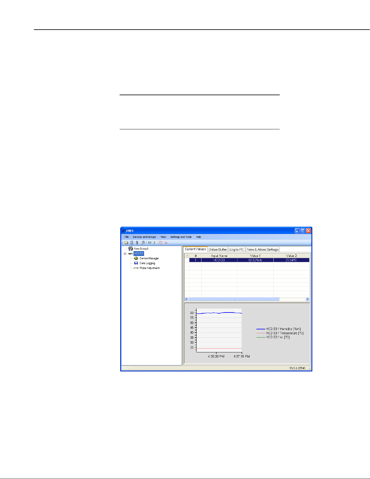
From the main screen, click on the “devices and groups”, search for “master
devices”, USB masters.
HW4 should find the probe, and show the current values:
B-2
Page 33
Appendix B. Changing the HC2S3 Settings
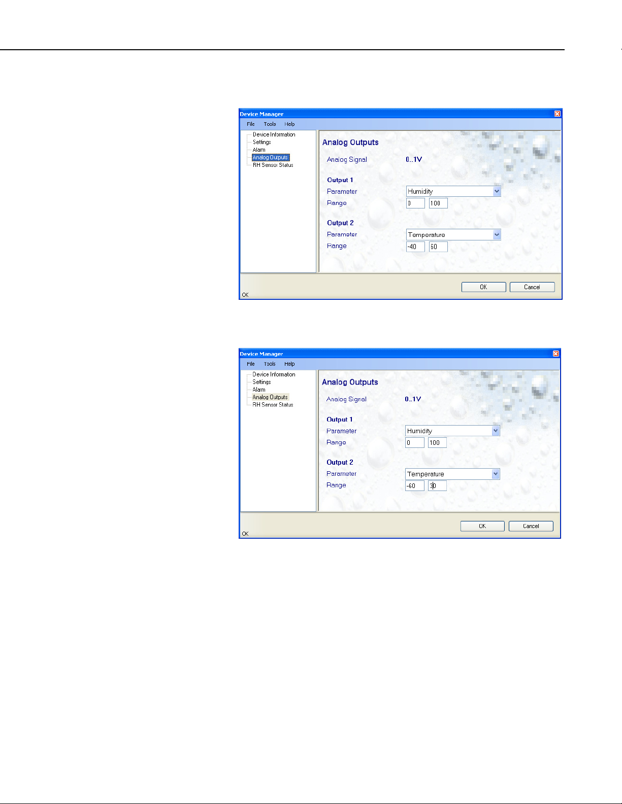
Click on “Device Manager”, select “Analog Outputs” to see the following
screen:
Change the lower and upper range values and click “OK”. The following
screen shows the range -60 to +30:
B.4 Multiplier and Offsets for Temperature Range
Analog Output 2 is 0 to 1V (1000 mV) for the temperature range. If the range
has been changed from the default (-40 to +60), then the multiplier and offset
for the measurement instruction will have to be changed from those shown for
the program examples in Section 7.4. For example, for a range of -60 to 30,
the multiplier to convert the measurement result ( mV) to temperature, is the
full scale range of temperature divided by the full scale range of mV, and the
Offset is -60.0 as shown below:
Multiplier = mV * (90°C/1000 mV)
= 0.09
Offset = -60.0
B-3
Page 34

Appendix B. Changing the HC2S3 Settings
Example measurement instructions for CR1000 datalogger, with the sensor
wired to SE channel 2:
Public AirTC
VoltSe (AirTC,1,mV2500,2,0,0,_60Hz,0.09,-60)
Example measurement instruction for CR10X datalogger:
1: Volt (SE) (P1)
1: 1 Reps
2: 5 2500 mV Slow Range
3: 2 SE Channel
4: 1 Loc [ AirTC ]
5: 0.09 Multiplier
6: -60.0 Offset
B-4
Page 35

Appendix C. HC2S3 Digital Communications
C.1 HC2S3 Digital Interface Specifications
The HC2S3 has a UART (Universal Asynchronous Receiver Transmitter) that
provides two-way digital communications with the probe. Interface cables can
be ordered through Rotronics for connecting the probe to an RS-485 port
(Rotronic pn E2-05XX-MOD), a computer's RS-232 port (Rotronic
pn AC3002), or USB port (Rotronic pn AC3001).
Connections to a CSI datalogger through an MD485 RS485 Interface or
SDM-SIO1 Serial I/O Module with the Rotronic E2-05XX-MOD RS-485 cable
are described in Section C.3 and C.4 respectively.
HC2S3 Digital Interface Specifications:
Interface Type: UART (Universal Asynchronous Receiver Transmitter)
Organization: Dialog, duplex
Default Configuration:
Baud rate: 19200
Parity: none
Data bits: 8
Stop fits: 1
Flow Control: none
Logical Levels:
Logical 0: <= 0.3V*VDD
Logical 1: <= 0.8V*VDD
C.2 HC2S3 Communications Protocol
Complete information on the HC2S3 Commands and Communication Protocol
can be found in the Rotronic E-M-AC3000-CP_XX
Rotronic's website www.rotronic-usa.com
The “RDD” command to “Read Values” is used in the example datalogger
programs to get temperature and relative humidity values from the probe, and
is described below.
RDD command: read values
.
manual, available from
Returns the measured and calculated values as well as the information
necessary to interpret the data (calculated parameter type, engineering units,
status, serial number and name of the device, etc.)
C-1
Page 36

Appendix C. HC2S3 Digital Communications
Command Format:
{ ID Adr RDD Chksum or } CR
Answer format:
ID Adr RDD Chksum or } CR
{
The data are returned according to the following structure:
Example Type Description
1..3 Byte Probe type (1= digital probe, 2=analog probe,
1234.56 Float Relative humidity or analog value
%RH String Humidity or analog value engineering unit
0..1 Bool Humidity or analog value alarm (out-of-limits)
+ Char Humidity or analog value trend (+,-,= or “ “)
1234.56 Float Temperature value
°C String Temperature engineering unit
0..1 Bool Temperature alarm (out-of-limits)
3=pressure probe)
= Char Temperature trend (+,-,= or “ “)
Dp String Calculated parameter type (nc: no calculation, Dp:
dew point, Fp: frost point)
1234.56 Float Calculated numerical value
°C String Calculated parameter engineering unit
0..1 Bool Calculated parameter alarm (out-of-limits)
+ Char Calculated parameter trend (+,-,= or “ “)
1..255 Byte Device type (HygroClip, Logger, HF, HM, …)
V1.0 String Firmware version
12345678 String Device serial number
Name String Device name
000…255 Byte Alarm Byte: (Bit0=out-of-limits value, Bit5= sensor
quality, Bit6 = humidity simulator, Bit7= temperature
simulator)
Example data returned from the RDD command:
{F00RDD} CR
{F00rdd 001; 4.45;%RH;000;=; 20.07;°C;000;=;nc;---.-;°C;000; ;001;V1.71;0060568338;HC2-S3 ;000;4
C-2
Page 37
Appendix C. HC2S3 Digital Communications
C.3 RS-485 Communications using an MD485 RS-485
Interface
The HC2S3 can be interfaced to a CSI datalogger through an MD485 RS-485
Interface using the Rotronic E2-05XX-MOD RS485 cable as described below.
Settings for the RS485 port on the MD485 must be configured to match the
configuration of the HC2S3, which are 19200 baud, No Parity, 8 Data Bits, 1
Stop bit, and No Flow Control.
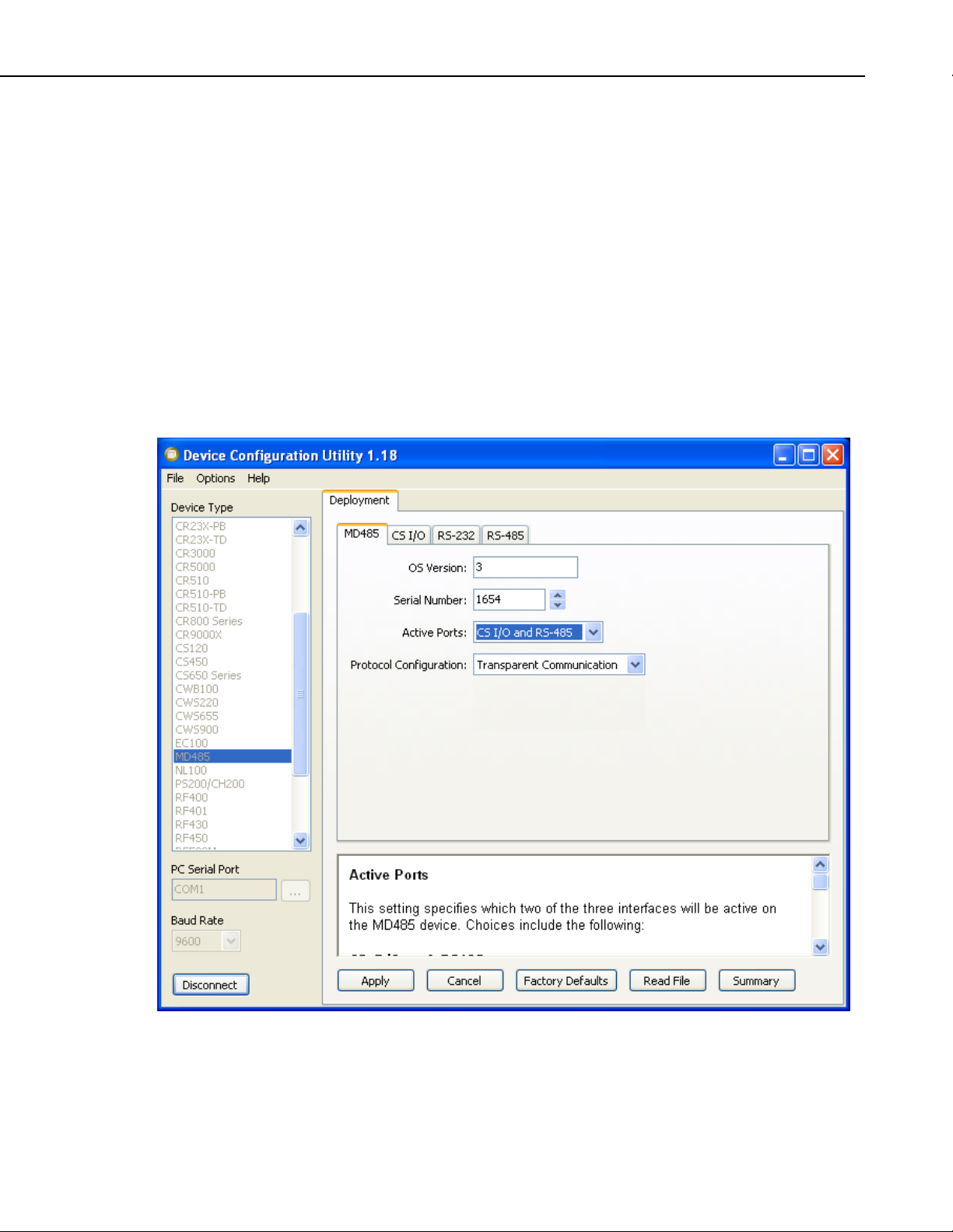
Device Configuration Utility (CSI software available as a free download) is
used to configure the MD485. Configuration settings for the MD485 are
shown below:
MD485 Tab: CS I/O AND RS-485
CS I/O Tab: SDC Address 7
RS485 Tab: RS485 baud 19200
C-3
Page 38

Appendix C. HC2S3 Digital Communications
Sensor Wiring:
E2-05XX-MOD Cable MD485 CR1000
Blue A
Red B
Green 12V
Gray/Yellow G
Clear Ground Symbol
NOTE
If the Rotronic cable includes brown and white wires (voltage
signals for temperature and humidity), CSI recommends
“capping” them with PN 27749 or equivalent insulated caps to
prevent the possibility of shorting.
Connect the CS I/O port of MD485 to CS I/O port on CR1000 with an SC12
cable.
The following example CR1000 program configures the CS I/O port as
COMSDC7 using the SerialOpen instruction, sends the RDD (Read Values)
command “|{F00RDD}CR” to the probe, and parses temperature and relative
humidity values from the data string returned by the probe.
Example CR1000 Program:
'CR1000 Program
'Declare variables
Public SerialIndest As String * 100
Dim String_1 As String
Const CRLF=CHR(13)+CHR(10)
Dim HC2S3_Split(17) As String * 40
Alias HC2S3_Split(2) = RH_Str 'RH string.
Alias HC2S3_Split(6) = TempC_Str 'Temp string.
Alias HC2S3_Split(17) = HC2S3_SN_Str 'HC2S3 serial number string.
Public TempC, RH, NBytesReturned
DataTable (Table1,1,-1)
DataInterval (0,15,Min,10)
Average (1,TempC,FP2,False)
Sample (1,RH,FP2)
EndTable
BeginProg
SerialOpen (ComSDC7,19200,0,0,100) 'Configure CS I/O port
String_1 = "|{F00RDD}"+CRLF 'RS485 command to send data
Scan (5,Sec,0,0)
SerialFlush (34)
SerialOut (ComSDC7,String_1,0,2,100) 'Send command to send data
Delay (0,500,mSec)
'Get data from probe
SerialInRecord (ComSDC7,SerialIndest,&H6464,0,&H3B48,NBytesReturned,01)
'Parse RH and temp from string
SplitStr (HC2S3_Split(),SerialIndest,";",17,7)
RH=RH_Str
TempC=TempC_Str
CallTable Table1
NextScan
EndProg
C-4
Page 39

Appendix C. HC2S3 Digital Communications
C.4 RS-485 Communications using an SDM-SIO1
Serial I/O Module
The HC2S3 can be interfaced to a CSI datalogger through an SDM-SIO1 Serial
I/O Module using the Rotronic E2-05XX-MOD RS485 cable as described
below.
The example program uses the SerialOpen instruction to configure the SDMSIO1 for RS-485 half duplex, “COMport 32” at 19200 baud, no parity, 1 stop
bit, and 8 data bits, and serial instructions to send the RDD command to get
temperature and relative humidity data from the probe.
Sensor Wiring:
E2-05XX-MOD Cable SDM-SIO1 CR1000
Blue Z
Red Y
Gray/Yellow G
Green 12V
Clear Ground
SDM-SIO1 Wiring:
SDM-SIO1 CR1000
C1 C1
C2 C2
C3 C3
G G
12V 12V
NOTE
If the Rotronic cable includes brown and white wires (voltage
signals for temperature and humidity), CSI recommends
“capping” them with PN 27749 or equivalent insulated caps to
prevent the possibility of shorting.
C-5
Page 40

Appendix C. HC2S3 Digital Communications
Example CR1000 Program:
'CR1000 Program
'Declare variables
Public SerialIndest As String * 100
Dim String_1 As String
Const CRLF=CHR(13)+CHR(10)
Dim HC2S3_Split(17) As String * 40
Alias HC2S3_Split(2) = RH_Str 'RH string.
Alias HC2S3_Split(6) = TempC_Str 'Temp string.
Alias HC2S3_Split(17) = HC2S3_SN_Str 'HC2S3 serial number string.
Public TempC, RH, NBytesReturned
Const SensorPort=32 'SDM-SIO1 rotary switch set at 0
DataTable (Table1,1,-1)
DataInterval (0,15,Min,10)
Average (1,TempC,FP2,False)
Sample (1,RH,FP2)
EndTable
BeginProg
SerialOpen (SensorPort,19200,51,100,200) '51 is for half duplex
String_1 = "|{F00RDD}"+CRLF 'RS485 command to send data
Scan (5,Sec,0,0)
SerialFlush (SensorPort)
SerialOut (SensorPort,String_1,0,1,100) 'Send command to send data
Delay (0,500,mSec)
'Get data from probe
SerialInRecord (ComSDC7,SerialIndest,&H6464,0,&H3B48,NBytesReturned,01)
'Parse RH and temp from string
SplitStr (HC2S3_Split(),SerialIndest,";",17,7)
RH=RH_Str
TempC=TempC_Str
CallTable Table1
NextScan
EndProg
C-6
Page 41

Page 42

Campbell Scientific Companies
Campbell Scientific, Inc. (CSI)
815 West 1800 North
Logan, Utah 84321
UNITED STATES
www.campbellsci.com
Campbell Scientific Africa Pty. Ltd. (CSAf)
Somerset West 7129
SOUTH AFRICA
www.csafrica.co.za
Campbell Scientific Australia Pty. Ltd. (CSA)
Garbutt Post Shop QLD 4814
www.campbellsci.com.au
Campbell Scientific do Brazil Ltda. (CSB)
Rua Luisa Crapsi Orsi, 15 Butantã
CEP: 005543-000 São Paulo SP BRAZIL
www.campbellsci.com.br
Campbell Scientific Canada Corp. (CSC)
11564 - 149th Street NW
Edmonton, Alberta T5M 1W7
www.campbellsci.ca
Campbell Scientific Centro Caribe S.A. (CSCC)
300 N Cementerio, Edificio Breller
Santo Domingo, Heredia 40305
www.campbellsci.cc
Campbell Scientific Ltd. (CSL)
Shepshed, Loughborough LE12 9GX
UNITED KINGDOM
www.campbellsci.co.uk
Campbell Scientific Ltd. (France)
3 Avenue de la Division Leclerc
www.campbellsci.fr
Campbell Scientific Spain, S. L.
Avda. Pompeu Fabra 7-9, local 1
www.campbellsci.es
Please visit www.campbellsci.com to obtain contact information for your local US or interna tional representative.
• info@campbellsci.com
PO Box 2450
• cleroux@csafrica.co.za
PO Box 8108
AUSTRALIA
• info@campbellsci.com.au
• suporte@campbellsci.com.br
CANADA
• dataloggers@campbellsci.ca
COSTA RICA
• info@campbellsci.cc
Campbell Park
80 Hathern Road
• sales@campbellsci.co.uk
92160 ANTONY
FRANCE
• info@campbellsci.fr
08024 Barcelona
SPAIN
• info@campbellsci.es
 Loading...