

Page 1
GRANITE 10 Specifications
Electrical specifications are valid over a -40 to +70 °C, noncondensing environment, unless otherwise specified. Extended
electrical specifications (noted as XD in specifications) are valid
over a -55 to +85 °C non-condensing environment.
Recalibration is recommended every three years. Critical
specifications and system configuration should be confirmed
with Campbell Scientific before purchase.
System specifications 1
Physical specifications 1
Power requirements 1
Power output specifications 2
Pulse measurement specifications 2
Digital input/output specifications 2
Communications specifications 3
Standards compliance specifications 4
Warranty 4
System specifications
Processor: NXP iMX6 Quad core running at 1 GHz
Memory:
l 2 GB DDR SDRAM
l 8 GB eMMC NAND OS storage
l 128 MB NOR FLASH
l 4 MB SRAM battery backed
l Data storage expansion: Removable microSD flash
memory, up to 16 GB
l USB host provides for portable data storage on a mass
storage device (MSD) formatted as FAT32. Not
intended for long term unattended data storage other
than what is available with TableFile().
GRANITE 10 Solid State Drive (SSD):
l SSD:Enhanced MLC
l SSD (XD):SLC
l Total onboard: 128 GB
l Humidity: 8% to 95%, non-condensing
l JESD219A client work load: 172 86 terabytes written
(TBW) (standard)
l Random write: 1828 TBW (XD)
l Sequential write: 10666 TBW (XD)
l Block PE cycle: 100000 (XD)
l Data Retention at 40 °C: 10 years with 10% PE cycle(XD)
Real-Time Clock:
GPS:
Wiring Panel Temperature: Measured using a thermistor,
located on the main processor board.
Physical specifications
Case Material: Stainless Steel 304 and Aluminum 6061
Dimensions: 21.4 x 12.0 x 7.5 cm (8.4 x 4.7 x 3.0 in); additional
clearance required for cables, wires, and antennas.
Weight/Mass: 1.2 kg (2.7 lb)
Power requirements
Protection: Power inputs are protected against surge, overvoltage, over-current, and reverse power. IEC 61000-4 Class 4
level.
Power In Terminal:
Internal Lithium Battery: 1/2AA, 1.2 Ah, 3.6 VDC (Tadiran
L5902S) for battery-backed memory and clock. 5-year life with
no external power source.
l MTBF (hours) at 25 °C: 1,500,000 (standard); 2,000,000
(XD)
l Typical power consumption at 12 VDC: 175 mA
(standard version); 212.5 mA (XD)
l Maximum sustained write power consumption at 12
VDC: 316.7 mA (XD only)
l Battery backed while external power is disconnected
l Resolution: 1 ms
l Accuracy: ±3 min. per year
l GPS Phase Lock to within 200 nS if used
l SMA Female 50 Ω input impedance
l Active antenna design, 3.3 Vdc
l 25 dBm maximum input
l Integrated SAW filtering and jam resistance
l 1 S time-to-fix during normal operation
l 35 S time-to-fix on power up or reboot
l 13 min. for leap second, once per day auto
l PPS ± 1 μS to full UTC second
l Receive sensitivity –161 dBm
l Voltage Input: 9.6 to 32 VDC
l Input Current Limit at 12 VDC:
o
Total system current is fused at 5 A with
replaceable automotive mini-blade fuse
Campbell Scientific, Inc.
© 2014, 2021
January 27, 2021
Page 2
Average Current Drain:
l Active: ~6 Watts
o
24 V input: 255 mA input
o
12 V input:495 mA input
Vehicle Power Connection: When primary power is pulled from
the vehicle power system, a second power supply OR charge
regulator may be required to overcome the voltage drop at
vehicle start-up.
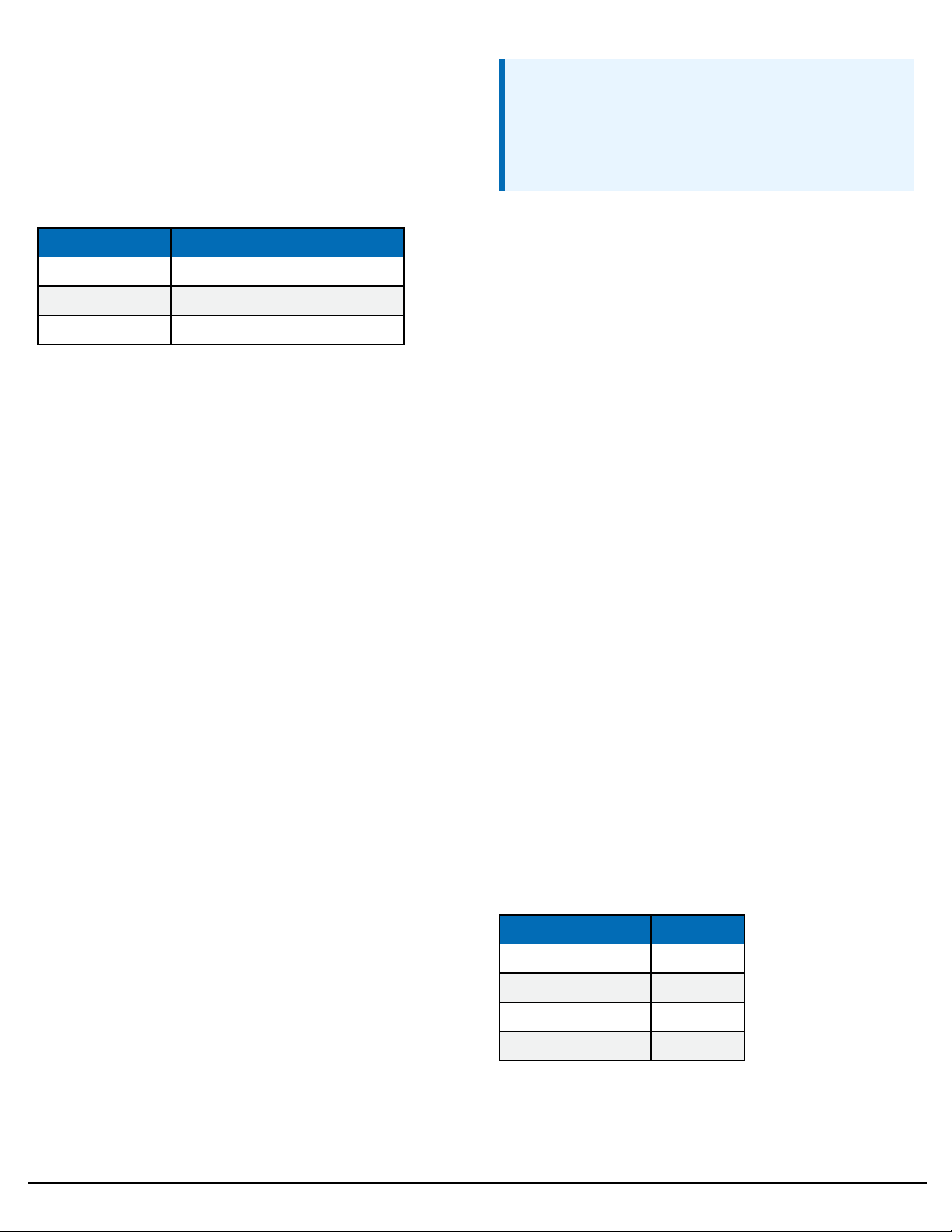
Wi-Fi Additional Current Contribution at 12 VDC:
Mode Wi-Fi Option
Client Mode 7 mA idle, 70 mA communicating
Access Point Mode 62 mA idle, 70 mA communicating
Sleep <1 mA
Power output specifications
System power out limits (when powered with
12VDC)
Total system current is fused at 5 A with replaceable
automotive mini-blade fuse
12 V and SW12 power output terminals
12V, SW12-1, and SW12-2: Provide 12 VDC power ±10% when
the power input supply voltage is ≥13.7VDC. When the supply
voltage is <13.7V the output voltage will be at least the supply
voltage minus 1.7 volts.
SW12-1 and SW12-2 can be independently set to a regulated
12V under program control.
SW12 current limit: 1100 mA
12 VDC outputs limited to 3300 mA, which is shared by all 12 V
outputs including 12V, SW12-1, SW12-2 and CS I/O pin 8.
5 V fixed output
5V: One regulated 5 V output. Supply is shared between the 5V
terminal and CS I/O pin 1.
l Voltage Output: Regulated 5 V output (±5%)
l Current Limit: 250 mA
C as power output
l C Terminals:
o
Output Resistance (Ro): 150 Ω
o
5 V Logic Level Drive Capacity: 10 mA @ 3.5 VDC
o
3.3 V Logic Level Drive Capacity: 10 mA @ 1.8
VDC
CSI/O pin 1
5 V Current Limit: 250 mA
CSI/O pin 8
Pulse measurement specifications
NOTE:
Conflicts can occur when a control port pair is used for
different instructions (TimerInput(), PulseCount(),
SDI12Recorder(), WaitDigTrig()). For example, if
C1 is used for SDI12Recorder(), C2 cannot be used for
TimerInput(), PulseCount(), or WaitDigTrig().
Maximum Input Voltage: ±20 VDC
Maximum Counts Per Channel: 2
Maximum Counts Per Scan: 2
Input Resistance: 5 kΩ
Accuracy: ±(6 ppm of reading + 0.00001)
Switch closure input
Terminals: C1-C8
Pull-Down Resistance: Configurable in terminal pairs with 100
kΩ
Pull-Up Resistance: Configurable in terminal pairs with 100 kΩ
(weak) or 2.2 kΩ (strong)
Maximum Input Frequency: 250 Hz
Minimum Switch Closed Time: 1 ms
Minimum Switch Open Time: 1 ms
Maximum Bounce Time: 1 ms open without being counted
Software Debounce Time: 1 ms
High-frequency input
Terminals: C1-C8
Pull-Down Resistance: Configurable in terminal pairs with 100
kΩ
Pull-Up Resistance: Configurable in terminal pairs with 100 kΩ
(weak) or 2.2 kΩ (strong)
Maximum Input Frequency: 1 MHz
Low-level AC input
DC-offset rejection: Internal AC coupling eliminates DC-offset
voltages up to ±0.05 VDC
Input Hysteresis: 12 mV at 1 Hz
Low-Level AC Pulse Input Ranges:
Sine wave (mV RMS) Range (Hz)
20 1.0 to 20
200 0.5 to 200
2000 0.3 to 10,000
5000 0.3 to 20,000
32
32
12 V Current Limit: 1100 mA
Digital input/output specifications
Terminals configurable for digital input and output (I/O)
including status high/low, pulse width modulation, external
GRANITE 10 Specifications | January 27, 2021 2
Page 3

interrupt, edge timing, switch closure pulse counting, highfrequency pulse counting, UART1, RS-2322, RS-4223, RS-4854,
SDM5, SDI-126, I2C7, and SPI8function. Terminals are
configurable in pairs for 5 V or 3.3 V logic for some functions.
NOTE:
Conflicts can occur when a control port pair is used for
different instructions (TimerInput(), PulseCount(),
SDI12Recorder(), WaitDigTrig()). For example, if
C1 is used for SDI12Recorder(), C2 cannot be used for
TimerInput(), PulseCount(), or WaitDigTrig().
Terminals:C1-C8
Maximum Input Voltage: ±20 V
Logic Levels and Drive Current:
Terminal Pair Configuration 5 V Source 3.3 V Source
Logic low ≤ 1.5 V ≤ 0.8 V
Logic high ≥ 3.5 V ≥ 2.5 V
Edge timing
Terminals:C1-C8
Maximum Input Frequency: 1 MHz
Resolution: 20 ns
Edge counting
Terminals:C1-C8
Maximum Input Frequency: 1 MHz
Quadrature input
Terminals: C1-C8 can be configured as digital pairs to monitor
the two sensing channels of an encoder.
Maximum Frequency: 500 kHz
Resolution: 20 ns or 50 MHz
Pulse-width modulation
Modulation Voltage: Logic high
1
Universal Asynchronous Receiver/Transmitter for asynchronous serial
communications.
2
Recommended Standard 232. A loose standard defining how twocomputing
devices can communicatewith each other. The implementation of RS-232 in
Campbell Scientificdataloggers to computer communications is quiterigid,but
transparent to mostusers.Features in the datalogger thatimplementRS-232
communication with smart sensors are flexible.
3
Communicationsprotocolsimilar to RS-485. Most RS-422 sensors willwork with
RS-485 protocol.
4
Recommended Standard 485. A standard defininghow two computing devices
can communicatewith each other.
5
Synchronous Device for Measurement.A processor-basedperipheral deviceor
sensor thatcommunicateswith the data logger via hardwireover a short distance
using a protocol proprietary to Campbell Scientific.
6
SerialDataInterfaceat1200 baud. Communication protocol for transferring data
between the data logger and SDI-12 compatiblesmart sensors.
7
Inter-IntegratedCircuitis a multi-master, multi-slave, packet switched,single-
ended, serialcomputer bus.
8
SerialPeripheralInterface- a clocked synchronous interface,usedfor short
distancecommunications, generally between embedded devices.
Maximum Period: 43 seconds
Resolution:10 ns
Maximum time between counter or timer instructions
l 86 seconds
Communications specifications
Ethernet Port: RJ45 jack, 10/100/1000 Base Mbps, full and half
duplex, Auto-MDIX, magnetic isolation, and TVS surge
protection, IEEE 802.3 compliant.
Internet Protocols: Ethernet, PPP, RNDIS, ICMP/Ping, Auto-IP
(APIPA), IPv4, IPv6, UDP, TCP, TLS (v1.2), DNS, DHCP, SLAAC,
Telnet, HTTP(S), SFTP, FTP(S), POP3/TLS, NTP, SMTP/TLS,
SNMPv3, CSI/OIP
Additional Protocols: CAN, CANFD, CPI, EPI, PakBus, PakBus
Encryption, SDM, SDI-12, Modbus RTU / ASCII / TCP, DNP3,
custom user definable over serial, UDP, NTCIP, NMEA 0183,
I2C, SPI
USB Device: Micro-B device for computer connectivity
USB Host: USB 2.0 full speed host 12 Mbps, Type-A for mass
storage devices
CS I/O: 9-pin D-sub connector to interface with Campbell
Scientific CS I/O peripherals.
0 – 5 V Serial(C1 to C8): Eight independent TX/RX pairs
SDI-12 (C1, C3, C5, C7): Four independent SDI-12 compliant
terminals are individually configured and meet SDI-12
Standard v 1.4.
RS-485 (C1 to C8): Two full duplex or four half duplex. Optional
120 Ohm termination resistor between pairs.
RS-422 (C1 to C8): Two full duplex or four half duplex. Use RS485 configuration.
RS-232 (C1 to C8): Four independent Tx/Rx pairs.
CPI A/B and RS-232 A/B: Two RJ45 module ports that can
operate in one of two modes: CPI or RS-232. CPI interfaces
with Campbell Scientific CDM measurement peripherals and
sensors. RS-232 connects, with an adapter cable, to computer,
sensor, or communications devices serially.
CAN:Four general purpose ports, CAN 2.0 up to 1 Mbps, or
CANFD up to 5 Mbps. Screw terminal or DSUB 15-pin
connections. Supports DBC files.
EPI: One EPI bus. 100 Mbps data rate. IEEE 1588
synchronization to 50 nS. 100 m (330 ft) maximum cable length
per network connection. Up to 15 devices. EPI is a proprietary
interface for communications between Campbell Scientific
data loggers and Campbell Scientific CDM peripheral devices.
It is based on Ethernet and IEEE 1588 Precision Time Protocol. It
consists of a physical layer definition and a data protocol.
CPI:Two independent CPI buses. Up to 1 Mbps data rate each.
Synchronization of devices to 5 μS. Total cable length up to
610 m (2000 ft). Up to 20 devices per bus. CPI is a proprietary
interface for communications between Campbell Scientific
GRANITE 10 Specifications | January 27, 2021 3
Page 4

data loggers and Campbell Scientific CDM peripheral devices.
It consists of a physical layer definition and a data protocol.
Wireless: Wi-Fi
Hardwired:Multi-drop, short haul, RS-232, fiber optic
Satellite: GOES, Argos, Inmarsat Hughes, Irridium
Wi-Fi specifications
WLAN (Wi-Fi)
Maximum Possible Over-the-Air Data Rates: <11 Mbps over
802.11b, <54 Mbps over 802.11g, <72 Mbps over 802.11n
Operating Frequency: 2.4 GHz, 20 MHz bandwidth
Antenna Connector: Reverse Polarity SMA (RPSMA)
Antenna (shipped with data logger): Unity gain (0 dBd), 1/2
wave whip, omnidirectional. Features an articulating knuckle
joint that can be oriented vertically or at right angles
Supported Technologies: 802.11 b/g/n, WPA/WPA2-Personal,
WPA/WPA2-Enterprise Security, WEP
Client Mode: WPA/WPA2-Personal and Enterprise, WEP
Access Point Mode: WPA2-Personal
Receive Sensitivity: -97 dBm
Standards compliance specifications
View EU Declarations of Conformity at
www.campbellsci.com/granite10.
EMIand ESD protection:
l Immunity: Meets or exceeds following standards:
o
ESD: per IEC 61000-4-2; ±15 kV air, ±8 kV contact
discharge
o
Radiated RF: per IEC 61000-4-3; 10 V/m, 80-1000
MHz
o
EFT: per IEC 61000-4-4; 4 kV power, 4 kV I/O
o
Surge: per IEC 61000-4-5; 4 kV power, 4kV I/O
o
Conducted RF: per IEC 61000-4-6; 10 V power, 10
V I/O
l Emissions and immunity performance criteria available
on request.
l United States FCC ID: XF6-RS9113SB
l Industry Canada (IC): 8407A-RS9113SB
NOTE:
The user is responsible for emissions if changing the
antenna type or increasing the gain.
Warranty
Standard:Three years against defects in materials and
workmanship.
Extended (optional):An additional two years. against defects in
materials and workmanship, bringing the total to 5 years.
GRANITE 10 Specifications | January 27, 2021 4
Page 5

Campbell Scientific regional offices
Australia
Location:
Phone:
Email:
Website:
Brazil
Location:
Phone:
Email:
Website:
Canada
Location:
Phone:
Email:
Website:
China
Location:
Phone:
Email:
Website:
Garbutt, QLD Australia
61.7.4401.7700
info@campbellsci.com.au
www.campbellsci.com.au
São Paulo, SP Brazil
11.3732.3399
vendas@campbellsci.com.br
www.campbellsci.com.br
Edmonton, AB Canada
780.454.2505
dataloggers@campbellsci.ca
www.campbellsci.ca
Beijing, P. R. China
86.10.6561.0080
info@campbellsci.com.cn
www.campbellsci.com.cn
France
Location:
Phone:
Email:
Website:
Germany
Location:
Phone:
Email:
Website:
India
Location:
Phone:
Email:
Website:
South Africa
Location:
Phone:
Email:
Website:
Vincennes, France
0033.0.1.56.45.15.20
info@campbellsci.fr
www.campbellsci.fr
Bremen, Germany
49.0.421.460974.0
info@campbellsci.de
www.campbellsci.de
New Delhi, DL India
91.11.46500481.482
info@campbellsci.in
www.campbellsci.in
Stellenbosch, South Africa
27.21.8809960
sales@campbellsci.co.za
www.campbellsci.co.za
Thailand
Location:
Phone:
Email:
Website:
UK
Location:
Phone:
Email:
Website:
USA
Location:
Phone:
Email:
Website:
Bangkok, Thailand
66.2.719.3399
info@campbellsci.asia
www.campbellsci.asia
Shepshed, Loughborough,
UK
44.0.1509.601141
sales@campbellsci.co.uk
www.campbellsci.co.uk
Logan, UT USA
435.227.9120
info@campbellsci.com
www.campbellsci.com
Costa Rica
Location:
Phone:
Email:
Website:
San Pedro, Costa Rica
506.2280.1564
info@campbellsci.cc
www.campbellsci.cc
Spain
Location:
Phone:
Email:
Website:
Barcelona, Spain
34.93.2323938
info@campbellsci.es
www.campbellsci.es
 Loading...