

Page 1
GPS16X-HVS
GPS Receiver
Revision
Copyright ©
Campbell Scientif
: 05/2020
2003 – 2020
ic, Inc.
Page 2

Table of Contents
PDF viewers: These page numbers refer to the printed version of this document. Use the
PDF reader bookmarks tab for links to specific sections.
1. Overview .................................................................... 1
1.1 Default Settings ....................................................................................1
1.2 Compatible Data Loggers.....................................................................2
1.3 Common Accessories ...........................................................................2
2. Precautions ................................................................ 2
3. Initial Inspection ........................................................ 3
4. QuickStart .................................................................. 3
5. Specifications ............................................................ 5
6. Installation ................................................................. 6
6.1 Wiring ..................................................................................................6
6.1.1 Using with an A300 ......................................................................8
6.2 Mounting ..............................................................................................9
7. GPS Data .................................................................... 9
7.1 $GPGGA Sentence (Position and Time) ............................................ 10
7.2 $GPRMC Sentence (Position and Time) ............................................ 11
8. CRBasic Programming ............................................ 11
8.1 GPS() Instruction ............................................................................... 11
8.2 Example Program Using GPS() Instruction ....................................... 13
9. Troubleshooting ...................................................... 14
9.1 Testing and Evaluating Serial Communications ................................ 15
9.1.1 Through a Direct Connection to the GPS16X-HVS ................... 15
9.1.2 Through a Data Logger Connected to the GPS16X-HVS ........... 15
9.2 NMEAStrings Variable Populated, but Clock Not Setting ................ 16
Appendices
A. Changing GPS16X-HVS Settings .......................... A-1
A.1 Computer Connections .................................................................... A-1
A.1.1 Using the A200 ........................................................................ A-1
A.1.1.1 Driver Installation .......................................................... A-1
A.1.1.2 Wiring ............................................................................ A-2
A.1.1.3 Powering the Sensor ...................................................... A-3
i
Page 3

Table of Contents
Determining which COM Port the A200 has been
A.1.1.4
Assigned .................................................................... A-3
A.1.2 Using the DB9-Female-to-Terminal-Block Interface .............. A-3
B. Serial Programming ............................................... B-1
Figures
1-1. The GPS16X-HVS terminates in pigtails for direct connection to
our data loggers.................................................................................1
6-1. CR1000 to GPS16X-HVS connection .................................................7
6-2. GPS16X-HVS mounted using a CM235 Magnetic Mounting Stand ...9
A-1. A200 Sensor-to-PC Interface .......................................................... A-2
Tables
1-1. Default Settings ....................................................................................1
6-1. Data Logger Wiring .............................................................................7
6-2. CR9000X Wiring .................................................................................8
6-3. GPS16X-HVS Wiring to A300 Terminals and Data Logger
Terminals ..........................................................................................8
6-4. A300 Cable Wiring to Data Logger Terminals ....................................9
7-1. NMEA $GPGGA String Definition ................................................... 10
A-1. A200 Wiring .................................................................................... A-2
A-2. DB9-Female-to-Terminal-Block Interface Wiring .......................... A-3
CRBasic Examples
8-1. Reading the GPS Using the GPS() Instruction ................................... 14
B-1. Reading the GPS Using Serial Programming ................................... B-1
ii
Page 4
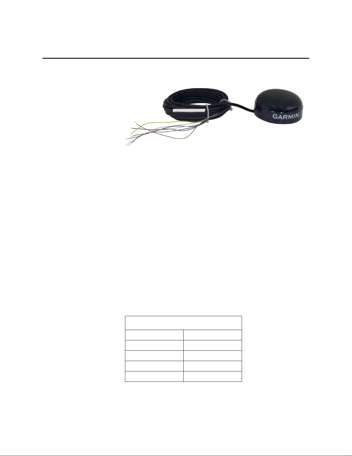
TABLE 1-1. Default Settings
GPS16X-HVS GPS Receiver
1. Overview
FIGURE 1-1. The GPS16X-HVS terminates in pigtails for direct
connection to our data loggers
The GPS16X-HVS is a complete GPS receiver manufactured by Garmin
International, Inc. Campbell Scientific configures the GPS16X-HVS to work
with our data loggers and modifies its cable so that the cable terminates in
pigtails. The pigtails connect directly to the control terminals of our data
loggers or with the aid of an A300.
The GPS16X-HVS includes the GPS receiver and antenna in the same housing
with one cable for the power supply and communications. The GPS antenna
must have a clear view of the sky. Generally, the GPS antenna will not work
indoors.
The GPS16X-HVS is a 12-channel GPS receiver that supports FAA Wide Area
Augmentation System (WAAS) or RTCM differential GPS. Also supported is
the 1 Pulse Per Second (PPS) timing signal. The cable connections provided
with the GPS16X-HVS do not support differential GPS correction. The cable
can be modified by the user if differential correction is required.
1.1 Default Settings
TABLE 1-1 shows the default settings of the GPSX16-HVS.
Baud Rate 38400 bps
Sentences Output GPGGA, GPRMC
Parity N (no parity)
Stop Bit 1
PPS 100 ms
1
Page 5
1.2 Compatible Data Loggers
NOTE
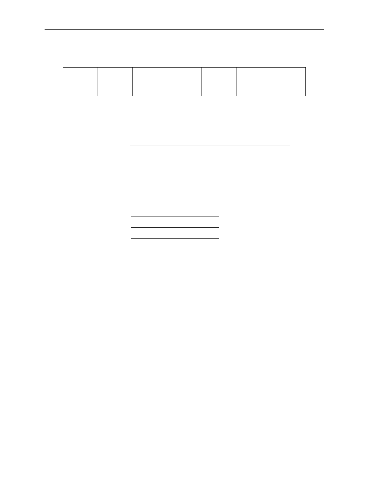
Compatible Contemporary Data Loggers
GPS16X-HVS GPS Receiver
CR300
Series
CR800
Series CR6 Series CR1000X CR1000 CR3000 CR9000X
*
*If PPS is required, the A300 Power and Signal Converter is needed.
**CPU Card RS-232 port only.
This manual provides information only for CRBasic data loggers.
For retired Edlog data logger support, see an older manual at
www.campbellsci.com/old-manuals.
Except for the CR9000(X), our data loggers use the CRBasic GPS() instruction
to read the GPS16X-HVS. To use the PPS functionality, some data loggers
need an updated clock chip. The clock chip is factory replaced (refer to
Assistance page for more information). Data loggers with the following serial
numbers need an updated chip:
Data Logger Serial Number
CR1000M < 20409
CR800 Series < 7920
CR3000 < 3168
In August 2014, Garmin changed the PPS output signal from 5 V to 3 V. Units
with serial numbers greater than 1A4189318 have a 3 V PPS output signal.
Because of this, the CR800-series, CR1000, and CR3000 data loggers need the
A300 power and signal converter to use the PPS signal output. The A300 is
NOT required for the CR6-series, CR1000X, or CR300-series data loggers.
* * **
1.3 Common Accessories
2. Precautions
The following common accessories are described at
www.campbellsci.com/gps16x-hvs:
• GPS16X-HVS Magnetic Mount
• CM235 Magnetic Mounting Stand
• A200 Sensor to PC Interface
• A300 Power and Signal Converter
• DB9 Female to Terminal Block with Hood and Hardware Kit
• READ AND UNDERSTAND the Safety section at the front of this
manual.
• When wiring the GPS16X-HVS, connect Ground before connecting 12V.
2
Page 6
3. Initial Inspection
Upon receipt of the GPS16X-HVS, inspect the packaging and contents for
damage. File damage claims with the shipping company.
4. QuickStart
A video that describes data logger programming using Short Cut is available at:
www.campbellsci.com/videos/cr1000x-datalogger-getting-started-programpart-3. Short Cut is an easy way to program your data logger to measure the
GPS16X-HVS and assign data logger wiring terminals. Short Cut is available
as a download on www.campbellsci.com. It is included in installations of
LoggerNet, RTDAQ, PC400, or PC200W.
The following procedure also describes using Short Cut to measure the
GPS16X-HVS.
1. Open Short Cut and select to create a new program.
2. Double-click the data logger model.
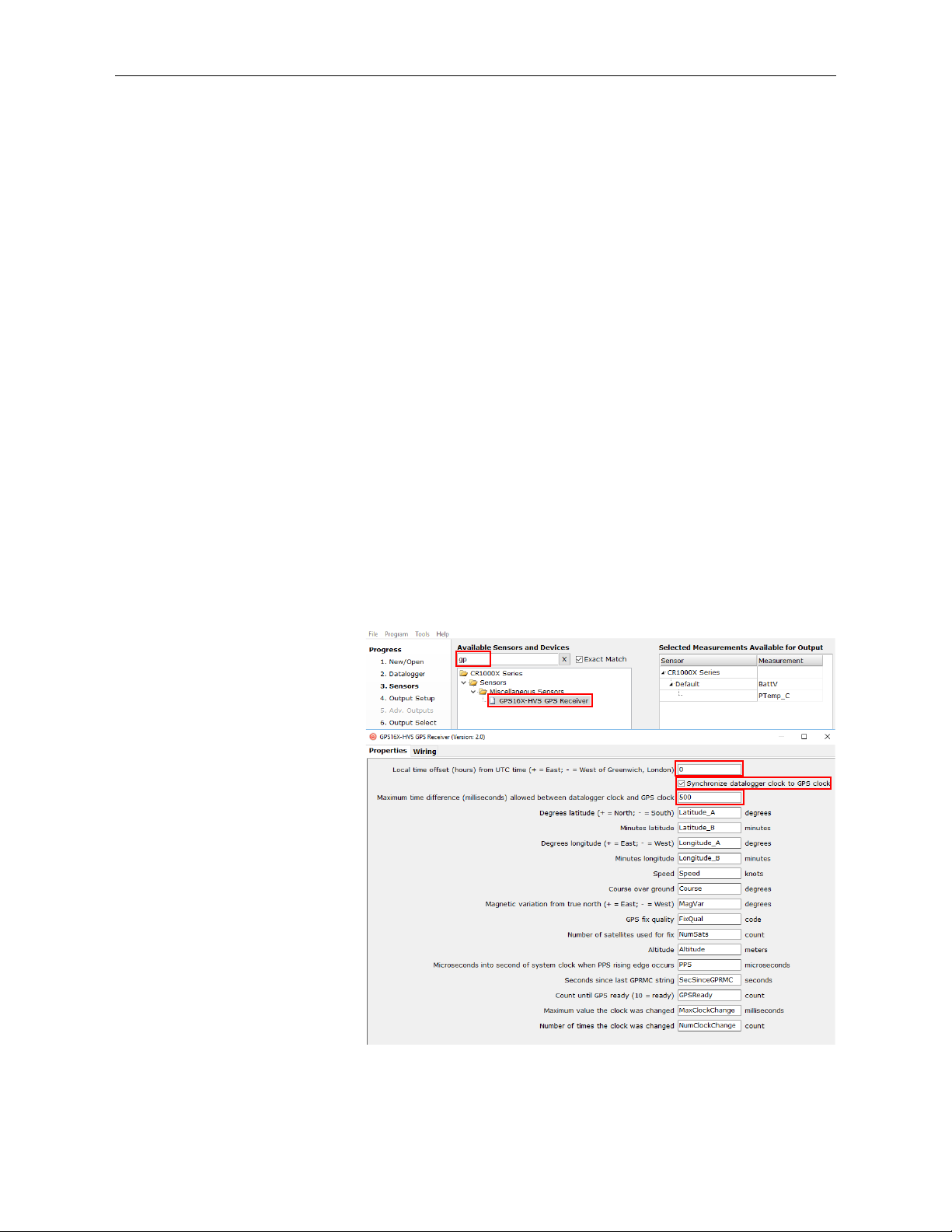
3. In the Available Sensors and Devices type GPS16X-HVS or find the
sensor in the Sensors > Miscellaneous Sensors folder. Double-click
GPS16X-HVS. Specify the Local time offset, whether to synchronize
datalogger clock to GPS clock, and the Maximum time difference
allowed between datalogger clock and GPS clock. You may also change
any of the default labels for the returned GPS values.
GPS16X-HVS GPS Receiver
3
Page 7
GPS16X-HVS GPS Receiver
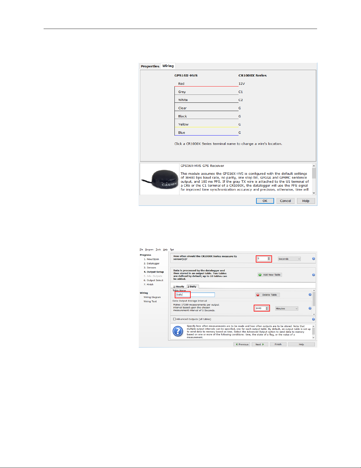
4. Click on the Wiring tab to see how the sensor is to be wired to the data
logger. Click OK after wiring the sensor.
5. Repeat steps three and four for other sensors. Click Next.
6. In Output Setup, type the scan rate, meaningful table names, and Data
Output Storage Interval.
4
Page 8
GPS16X-HVS GPS Receiver
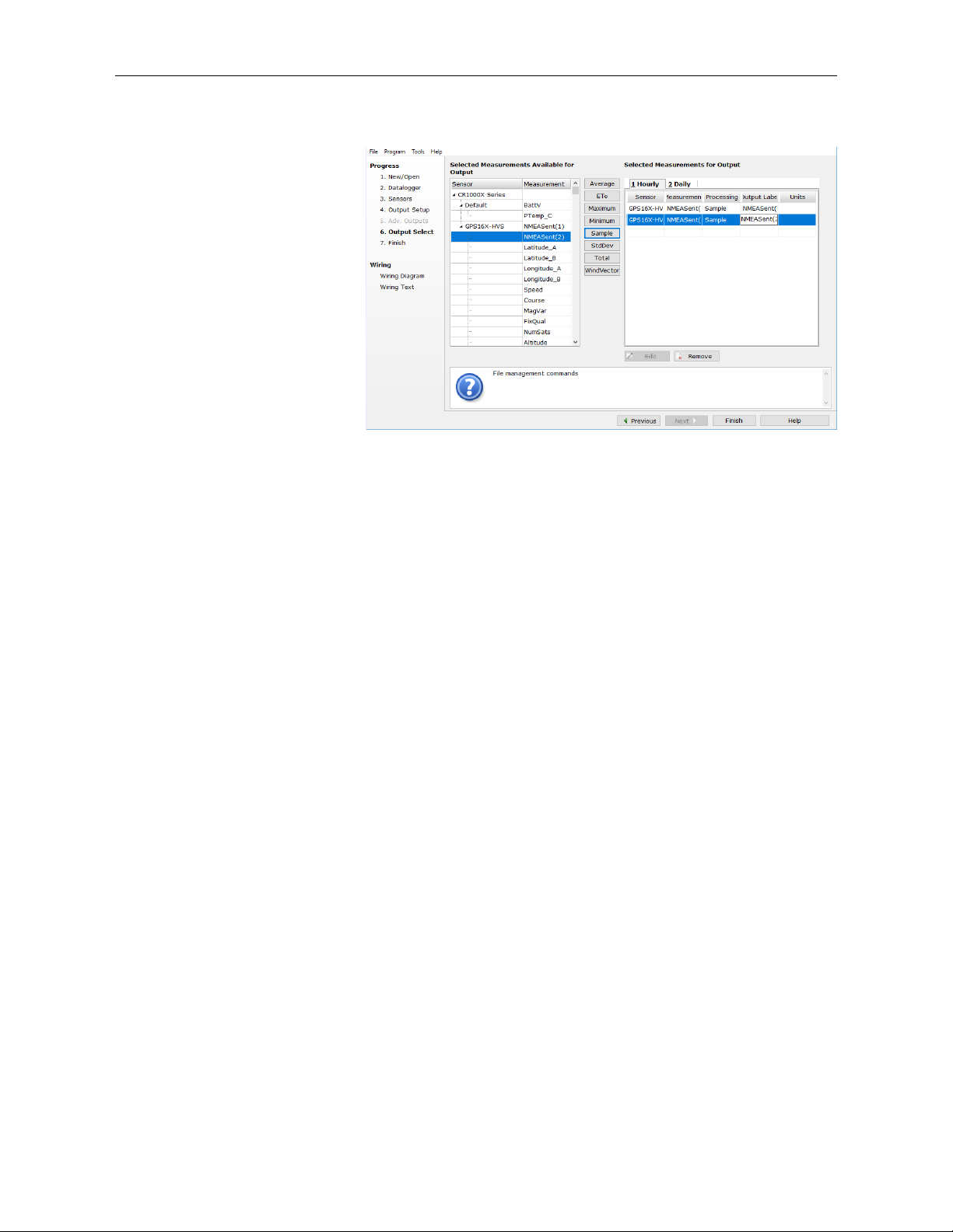
7. Select the output options.
8. Click Finish and save the program. Send the program to the data logger if
the data logger is connected to the computer.
9. If the sensor is connected to the data logger, check the output of the sensor
in the data display in LoggerNet, RTDAQ, PC400, or PC200W to make
sure it is making reasonable measurements.
5. Specifications
Physical
Size: 86 mm (3.39 in) diameter, 42 mm (1.65 in) high
Weight: 181 g (6.4 oz) without cable, 332 g (11.7 oz) with 5 m
Cable: PVC-jacketed, 5 m, foil-shielded, 8-conductor, 28 AWG
Electrical Characteristics
Input Voltage: 8.0 VDC to 40 VDC unregulated
Current Drain: 65 mA @ 12 VDC
GPS Receiver
Sensitivity: –185 dbW minimum
GPS Performance
Receiver: WAAS enabled; 12 parallel channel GPS receiver
cable
continuously tracks and uses up to 12 satellites, 11 if
PPS is active
5
Page 9

GPS16X-HVS GPS Receiver
Acquisition Times (Approximate)
Reacquisition: Less than 2 s
Hot: 1 s (all data known)
Warm: ~38 s (initial position, time and almanac known,
ephemeris unknown)
Cold: ~45 s
SkySearch: 5 min (no data known)
Sentence Rate: 1 s default; NMEA 0183 output interval configurable
from 1 to 900 s in one second increments
Accuracy: GPS Standard Positioning Service (SPS)
Position: Less than 15 m, 95% typical (100 m with selective
availability on)
Velocity: 0.1 knot RMS steady state
DGPS (USCG/RTCM)
Position: 3-5 m, 95% typical
Velocity: 0.1 knot RMS steady state
DGPS (WAAS)
Position: Less than 3 m
Velocity: 0.1 knot RMS steady state
6. Installation
6.1 Wiring
PPS Time: ±1 microsecond at rising edge of PPS pulse (subject to
selective availability)
Dynamics: 999 knots velocity (limited above 60,000 ft, 6g
dynamics)
Interfaces: True RS-232 output, asynchronous serial input
compatible with RS-232 or TTL voltage levels, RS-232
polarity. Selectable baud rates (4800, 9600, 19200,
38400)
PPS: 1 Hz pulse, programmable width, 1 microsecond
accuracy
Power Control
Off: Open circuit
On: Ground or pull to low logic level < 0.3 VDC
Environmental Characteristics
Temperature: –30 to 80 °C operational, –40 to 80 °C storage
The GPS16X-HVS connects directly to a CR6-series, CR3000, CR1000X,
CR800-series, CR300-series, or CR1000 data logger (see TABLE 6-1).
However, if PPS is required, the A300 Power and Signal Converter may be
required for use with the CR800 series, CR1000, and CR3000. See Section
6
Page 10

GPS16X-HVS GPS Receiver
TABLE 6-1. Data Logger Wiring
⏚
6.1.1, Using with an A300
(p. 8). The CR6 series, CR1000X series, and CR300
series do not require the A300.
Use the DB9-Male-to-Terminal-Block interface to connect the GPS16X-HVS
to the RS-232 port of the CR9000X CPU card. See TABLE 6-2.
To change the default settings, connect the GPS16X-HVS to a computer.
Either use the A200 interface to connect to a computer USB port or the
DB9-Female-to-Terminal-Block interface to connect to a computer serial port
(see Appendix A, Changing GPS16X-HVS Settings
(p. A-1)).
GPS16X-HVS Data Logger Function
Red 12V Power In
Black G Power Ground
Yellow G or C (control terminal)
Ground or
Power Switch
White C or U configured for Rx1 TXD
Gray C or U configured for Tx or PPS1 RXD or PPS
Blue G Ground
Shield
1
U terminals are automatically configured by the measurement instruction.
Shield
FIGURE 6-1. CR1000 to GPS16X-HVS connection
7
Page 11

GPS16X-HVS GPS Receiver
TABLE 6-2. CR9000X Wiring
TABLE 6-3. GPS16X-HVS Wiring to A300 Terminals
GPS16X-HVS CR9000X Function
*All of the grounds to the RS-232 pin 5 (using the DB9-Male-to-Terminal Block
interface). A 5-position terminal connector can be used to facilitate connecting all of the
wires into the same terminal.
6.1.1 Using with an A300
In 2014, Garmin changed the pulse-per-second (PPS) output of the
GPS16X-HVS from 5 V to 3 V. Units with a serial number 1A4189318 or
greater have a PPS output of 0 to 3 V. For those units, an A300 is needed to
connect the PPS output to a CR800-series, CR3000, or CR1000 data logger.
Those data loggers require the PPS line to have a voltage of 3.8 V or greater.
Red
Black
Yellow
White
Gray
12 V (SDM or 9011
connector)
Ground (SDM or 9011
connector)*
Ground (SDM or 9011
connector)*
RS-232 pin 3 (using
28841)
RS-232 pin 9 (using
28841)
Power In
Power Ground
Power Switch
TXD
PPS
Blue No Connection N/A
Shield
Ground (SDM or 9011
connector)*
Shield
GPS16X-HVS
Wire Color
Red 12 V 12V
Black Ground G
Yellow Enable G or C terminal
White TXD (Output) C (even) (Rx)
Gray PPS 3.3V IN
Blue Ground Ground
Shield Shield Ground
and Data Logger Terminals
GPS16X-HVS
Wire Function
A300
Terminal
Data Logger
8
Page 12

TABLE 6-4. A300 Cable Wiring to Data Logger Terminals
A300 Wire Color
A300 Wire Function
Data Logger
G
G
6.2 Mounting
GPS16X-HVS GPS Receiver
Red 12 V 12V
Black Ground
Green 5 V Signal Input
White 5 V Signal Output C (Tx)
The GPS16X-HVS mounts to a mast or crossarm using the CM235 Magnetic
Mounting Stand. Typically, the GPS16X-HVS mounts to the CM235
magnetically with the Magnetic Mount. Alternatively, the GPS16X-HVS can
be mounted directly to the CM235 using three M4 screws supplied with the
17212 or by the customer.
FIGURE 6-2. GPS16X-HVS mounted using a CM235 Magnetic
Mounting Stand
7. GPS Data
The GPS16X-HVS has several data formats available. The GPS16X-HVS is
configured to output the NMEA $GPGGA and $GPRMC time and position
string. It is possible to configure the GPS16X-HVS to output other NMEA
strings including the $GPVTG track made good and ground speed string. See
Appendix A, Changing GPS16X-HVS Settings
(p. A-1), for details.
9
Page 13

7.1 $GPGGA Sentence (Position and Time)
TABLE 7-1. NMEA $GPGGA String Definition
Sample NMEA $GPGGA data string:
$GPGGA,hhmmss,llll.lll,a,nnnnn.nnn,b,t,uu,v.v,w.w,M,x.x,M,y.y,zzzz*hh<CR><LF>
Field Description
0 $GPGGA NMEA string identifier
1 hhmmss UTC of Position: Hours, minutes, seconds
2 1111.111 Latitude: Degrees, minutes, thousandths of minutes
3 a N (North) or S (South)
4 nnnnn.nnn Longitude: Degrees, minutes, thousandths of minutes
5 b E (East) or W (West)
GPS16X-HVS GPS Receiver
6 t
7 uu Number of Satellites in Use
8 v.v Horizontal Dilution of Precision (HDOP)
9 w.w Antenna Altitude in Meters
10 M M = Meters
11 x.x Geoidal Separation in Meters
12 M
13 y.y
14 zzzz Differential Reference Station ID (0000 to 1023)
15 * Asterisk, generally used as the termination character
16 hh Checksum
17 <CR><LF> Carriage return, line feed characters.
Sample $GPGGA output strings:
GPS Quality Indicator: 0 = No GPS, 1 = GPS, 2 =
DGPS
M = Meters. Geoidal separation is the difference
between the WGS-84 earth ellipsoid and mean-sealevel.
Age of Differential GPS Data. Time in seconds since
the last Type 1 or 9 Update
Cold Start
No satellites acquired, Real Time Clock and Almanac invalid:
$GPGGA,,,,,,0,00,,,,,,,*66
Warm Start
No satellites acquired, time from Real Time Clock, almanac valid:
$GPGGA,235032.0,,,,,0,00,,,,,,,*7D
Warm Start
One satellite in use, time from GPS Real Time Clock (not GPS), no position:
$GPGGA,183806.0,,,,,0,01,,,,,,,*7D
10
Page 14

Valid GPS Fix
NOTE
Three satellites acquired, time and position valid:
$GPGGA,005322.0,4147.603,N,11150.978,W,1,03,11.9,00016,M,-016,M,,*6E
7.2 $GPRMC Sentence (Position and Time)
Example (signal not acquired):
$GPRMC,235947.000,V,0000.0000,N,00000.0000,E,,,041299,,*1D
Example (signal acquired):
$GPRMC,092204.999,A,4250.5589,S,14718.5084,E,0.00,89.68,211200,,*25
Field Example Comments
Sentence ID $GPRMC
UTC Time 092204.999 hhmmss.sss
Status A A = Valid, V = Invalid
Latitude 4250.5589 ddmm.mmmm
N/S Indicator S N = North, S = South
Longitude 14718.5084 dddmm.mmmm
GPS16X-HVS GPS Receiver
E/W Indicator E E = East, W = West
Speed over ground 0.00 Knots
Course over ground 0.00 Degrees
UTC Date 211200 DDMMYY
Magnetic variation Degrees
Magnetic variation E = East, W = West
Checksum *25
Terminator CR/LF
8. CRBasic Programming
This section describes programming a CR6-series, CR3000, CR1000X,
CR800-series, CR300-series, CR1000, or CR9000X data logger.
8.1 GPS() Instruction
The GPS() instruction is used along with a GPS device to set the data logger
clock. This instruction will also provide information such as location
(latitude/longitude) and speed, and store NMEA sentences from the GPS
device.
To use the GPS() instruction, the data logger operating system
(OS) should be OS17 or higher for the CR1000; OS10 or higher
for the CR3000; or OS08 or higher for the CR800 series. Go to
www.campbellsci.com/downloads to upgrade the data logger OS.
11
Page 15

GPS16X-HVS GPS Receiver
The resolution of accuracy for the clock set is typically 10 microseconds. Some
older CR3000, CR800-series, and CR1000 data loggers (hardware revision
number less than or equal to 007 in RevBoard field in the data logger Status
table) have a resolution of 10 milliseconds. The clock set relies on information
from the GPRMC sentence. If this sentence is not returned, a clock set will not
occur.
By default, the instruction expects the GPS unit to be set up at 38400 baud,
outputting the GPRMC and GPGGA sentences once per second. The data
logger expects the start of the second to coincide with the rising edge of the
PPS signal. If there is no PPS signal or if the required sentences come out at
less than once per second, the data logger will not update its clock.
GPS units with lower baud rates can be used with the GPS() instruction but the
baud rate has to be set for the relevant Com port it is to be connected to either
in the data logger settings or by including a SetStatus() command after the
BeginProg() instruction in the program (for example,
SetStatus("BaudrateCOM4",19200)).
Baud rates of 2400 bps or lower will not work as the GPS unit will not transmit
the two GPS sentences once per second reliably. Similar problems can be
encountered even at higher baud rates if too many optional GPS strings are
selected to be output.
The GPS() instruction has the following syntax:
GPS(GPSArray,ComPort,TimeOffset,MaxTimeDiff,NMEAStrings)
Description of the parameters follows:
GPSArray The GPSArray parameter is the variable in which to store the
information returned by the GPS. Fifteen values are returned.
If this array is not dimensioned to 15, values will be stored to
fill the array and no error will be returned. If no values are
available, NAN will be returned. The following values are
returned by the GPS:
Array(1) = Latitude, degrees
Array(2) = Latitude, minutes
Array(3) = Longitude, degrees
Array(4) = Longitude, minutes
Array(5) = Speed over ground, knots
Array(6) = Course over ground, degrees
Array(7) = Magnetic variation (positive = East, negative =
West)
Array(8) = Fix Quality (0 = invalid, 1 = GPS, 2 = differential
GPS, 6 = estimated)
Array(9) = Number of Satellites
Array(10) = Altitude, meters
Array(11) = Pulse per second (PPS) length, microseconds
Array(12) = Seconds since last GPRMC sentence
Array(13) = GPS Ready, 10 = ready
Array(14) = Maximum clock change, milliseconds (10 msec
resolution)
Array(15) = Clock change count
12
Page 16

GPS16X-HVS GPS Receiver
ComPort The ComPort parameter is the control terminal pair to which
the GPS device is attached. Valid options are COM1 (C1/C2),
COM2 (C3/C4), COM3 (C5/C6), and COM4 (C7/C8). Rx is
used to read in the NMEA sentences and Tx is used to monitor
the PPS from the GPS. This instruction defaults to a baud rate
of 38,400 bps. If a different baud rate is required, use the
SetStatus() instruction to override the default.
TimeOffset The TimeOffset parameter is the local time offset, in seconds,
from UTC.
MaxTimeDiff The MaxTimeDiff parameter is the maximum difference in
time between the data logger clock and the GPS clock that will
be tolerated before the clock is changed. If a negative value is
entered, the clock will not be changed.
For data loggers prior to hardware revision 08, the
MaxTimeDiff parameter should not be set to 0. A minimum
value of 20 ms is recommended. With this hardware, when a
GPS() instruction is in the program the clock is checked each
second (regardless of how often the GPS() instruction is run).
The clock is set if any difference is found. This can result in
the clock being set each second, resulting in skipped records in
the data table(s). This restriction does not apply to hardware
revisions 08 or greater.
NMEAStrings The NMEAStrings parameter is the string array that holds the
NMEA sentences. If it exists, the GPRMC sentence will reside
in NMEAStrings(1), and the GPGGA sentence will reside in
NMEAStrings(2). Any other sentences will reside in
subsequent indexes into the array (on a first-in basis). Once an
index in the array is used to store a particular sentence, that
sentence will always be stored in that location when updates to
the sentence are received.
8.2 Example Program Using GPS() Instruction
The following wiring and short program provide an example of using the
GPS() instruction with the Garmin GPS16X-HVS.
13
Page 17

CRBasic Example 8-1. Reading the GPS Using the GPS() Instruction
'Program the GPS16-HVS to use 38.4 kbaud, no parity, 8 data bits, and 1 stop bit
PipeLineMode
EndProg
Const LOCAL_TIME_OFFSET = -6 'Local time offset relative to UTC time
Dim nmea_sentence(2) As String * 100
Public gps_data(15)
Alias gps_data(1) = latitude_a 'Degrees latitude (+ = North; - = South)
Alias gps_data(2) = latitude_b 'Minutes latitude
Alias gps_data(3) = longitude_a 'Degress longitude (+ = East; - = West)
Alias gps_data(4) = longitude_b 'Minutes longitude
Alias gps_data(5) = speed 'Speed
Alias gps_data(6) = course 'Course over ground
Alias gps_data(7) = magnetic_variation 'Magnetic variation from true north (+ =
'East; - = West)
Alias gps_data(8) = fix_quality 'GPS fix quality: 0 = invalid, 1 = GPS, 2 =
'differential GPS, 6 = estimated
Alias gps_data(9) = nmbr_satellites 'Number of satellites used for fix
Alias gps_data(10) = altitude 'Antenna altitude
Alias gps_data(11) = pps 'usec into sec of system clock when PPS
'rising edge occurs, typically 990,000 once
'synced
Alias gps_data(12) = dt_since_gprmc 'Time since last GPRMC string, normally less
'than 1 second
Alias gps_data(13) = gps_ready 'Counts from 0 to 10, 10 = ready
Alias gps_data(14) = max_clock_change 'Maximum value the clock was changed in msec
Alias gps_data(15) = nmbr_clock_change 'Number of times the clock was changed
'Define Units to be used in data file header
Units latitude_a = degrees
Units latitude_b = minutes
Units longitude_a = degrees
Units longitude_b = minutes
Units speed = knots
Units course = degrees
Units magnetic_variation = unitless
Units fix_quality = unitless
Units nmbr_satellites = unitless
Units altitude = m
Units pps = ms
Units dt_since_gprmc = s
Units gps_ready = unitless
Units max_clock_change = ms
Units nmbr_clock_change = samples
BeginProg
'Use SetStatus prior to scan if baud rate needs to be changed for device
Scan (1,Sec,0,0)
GPS (latitude_a,Com4,LOCAL_TIME_OFFSET*3600,100,nmea_sentence(1))
NextScan
GPS16X-HVS GPS Receiver
9. Troubleshooting
Testing and evaluation of serial communications is best done by reducing the
whole system to small manageable systems. Usually some portions of the
whole system are working. The first steps involve finding what is working.
During this process, you may find parts of the system that are not working or
mistakes that can be easily corrected. Fix each subsystem before testing others.
14
Page 18

GPS16X-HVS GPS Receiver
DB9-Female-to-Terminal-Block Connections
9.1 Testing and Evaluating Serial Communications
9.1.1 Through a Direct Connection to the GPS16X-HVS
Test the GPS16X-HVS for proper operation including the baud rate and output
string. Use a computer, terminal emulator software, a serial port (RS-232), and
a DB9 to Terminal Block Interface. The computer and serial port can be the
same as used to communicate with the data logger. Terminal emulation
software is common. Hyperterm is supplied as part of Windows™ and works.
Procomm™ is another communication software package that works well.
Set up the software for the correct serial port, 38.4 kbps, 8 data bits, 1 stop bit
and no parity. Flow control should be none. Using the DB9-Female-to-TerminalBlock interface, connect the GPS16X-HVS to the computer serial port. Power up
the GPS16X-HVS. The GPS antenna should have a clear view of the sky. Don’t
expect the GPS antenna to work indoors. The $GPGGA and GPRMC strings
should be displayed once a second. Make sure the $GPGGA string is showing a
valid GPS fix. A valid GPS fix will display time, position and have a GPS
quality number greater than zero.
GPS16X Receiver DB9 to Terminal Block Interface
White Pin 2
Black and Yellow Pin 5 (shares power ground)
9.1.2 Through a Data Logger Connected to the GPS16X-HVS
Serial communication can also be tested using the data logger terminal mode
watch command, also known as sniffer mode. To enter sniffer mode:
1. Connect to your data logger in the Device Configuration Utility and select
the Terminal tab. (You can also use the Terminal Emulator in PC200W,
PC400, or the LoggerNet Connect screen.)
2. Press Enter until a datalogger_type> prompt (for example, CR1000X>)
appears.
3. Type W and press Enter.
4. In response, the query Select: is presented with a list of available
terminals. Enter the port number assigned to the terminal to which the
GPS16X-HVS is connected, and press Enter.
5. In answer to Enter timeout (secs):, type 100 and press Enter.
6. In response to the query ASCII (Y)?, type Y and press Enter.
7. Communication between the data logger and GPS16X-HVS is now open
If you see no communication, the GPS16X-HVS is hooked up incorrectly, is
not powered, or does not have the yellow wire tied to ground. If you see
readable NMEA strings coming in but many fields are not populated, you most
for viewing.
15
Page 19

GPS16X-HVS GPS Receiver
likely need to go outside to obtain a better signal. If you see “garbage”
characters coming in (that is, non-NMEA strings), there is likely a baud rate
mismatch.
9.2 NMEAStrings Variable Populated, but Clock Not Setting
Look at the GPSReady variable. It will increment from 0 to 10 when the data
logger has received good GPRMC strings and a synchronized PPS signal. Once
GPSReady reaches 10, the data logger will begin to use GPS time for clock
setting. The 12th value populated in GPSArray indicates elapsed time since a
GPRMC string was received and should not exceed 1. If the GPRMC string is
being received and GPSReady remains at zero, the PPS signal is not being
received by the data logger.
16
Page 20

Appendix A. Changing GPS16X-HVS Settings
As configured by Campbell Scientific, the GPS16X-HVS will output the
NMEA 0183 $GPGGA and $GPRMC data strings once a second, the PPS
signal is enabled with a duration of 100 milliseconds and the baud rate is set to
38,400 baud.
Special software (SNRSRCFG.EXE) is available from Garmin International
for system setup. The GPS16X-HVS user manual available from Garmin
International provides technical details beyond the scope of the Campbell
Scientific user manual.
Settings used by Campbell Scientific for GPS16X-HVS setup:
GPS Base Model = GPS 16(X)
Fix Mode = Automatic
Baud Rate = 38,400
Dead Reckon Time = 30 sec
NMEA output time = 1 sec
Position pinning = off
NMEA 2.30 mode = off
Power Save Mode = off (Normal mode)
PPS mode = 1 Hz
PPS Length = 100 mS
Phaze output Data = off
DGPS Mode = WAAS only
Differential mode = Automatic
Earth Datum Index = WGS 84
Selected Sentences = GPGGA and GPRMC
Common changes would be baud rate and selected sentences. The NMEA 0183
GPVTG data sentence gives ground speed and direction, which may be
required for some applications. Changes can be made with the Garmin
software, or with a terminal emulator and the Garmin technical user manual.
Contact Garmin International (www.garmin.com) for either resource.
A.1 Computer Connections
Either an A200 interface or a DB9-Female-to-Terminal-Block interface is
required to connect the GPS16X-HVS to a computer. The A200 is used to
connect to a computer USB port, and the DB9 Female to Terminal Block is
used to connect to a computer 9-pin serial port.
A.1.1 Using the A200
A.1.1.1 Driver Installation
If the A200 has not been previously plugged into your computer, the A200
driver needs to be loaded onto your computer.
A-1
Page 21

A.1.1.2 Wiring
TABLE A-1. A200 Wiring
NOTE
Appendix A. Changing GPS16X-HVS Settings
Drivers should be loaded before plugging the A200 into the
computer. The A200 drivers can be downloaded, at no charge,
www.campbellsci.com/downloads.
from:
One end of the A200 has a terminal block while the other end has a type B
female USB port. The terminal block provides 12V, G, TX, and RX terminals
for connecting the GPS16X-HVS (see FIGURE A-1 and TABLE A-1).
A data cable ships with the A200. This cable has a USB type-A male connector
that attaches to a computer USB port, and a type B male connector that
attaches to the A200 USB port.
Color
Red 12V +12 Vdc
Black G G
Yellow G G
White Tx Tx
Gray PPS No Connection
Blue Rx Rx
Shield sig ground G
Sensor
Cable Label
A200
Terminal
FIGURE A-1. A200 Sensor-to-PC Interface
A-2
Page 22

Appendix A. Changing GPS16X-HVS Settings
TABLE A-2. DB9-Female-to-Terminal-Block
A.1.1.3 Powering the Sensor
The A200 provides power to the GPS16X-HVS when it is connected to a
computer USB port. An internal DC/DC converter boosts the 5 VDC supply
from the USB connection to a 12 VDC output that is required to power the
sensor.
A.1.1.4 Determining which COM Port the A200 has been Assigned
When the A200 is loaded, the A200 is assigned a COM port number. Often, the
assigned COM port will be the next port number that is free. However, if other
devices have been installed in the past (some of which may no longer be
plugged in), the A200 may be assigned a higher COM port number.
Often, the assigned COM port will be the next port number that is free.
However, if other devices have been installed in the past (some of which may
no longer be plugged in), the A200 may be assigned a higher COM port
number. To check which COM port has been assigned to the A200, you can
monitor the appearance of a new COM port in the list of COM ports offered in
your software package, such as LoggerNet, before and after the installation, or
look in the Windows Device Manager list under the ports section (access via
the control panel).
A.1.2 Using the DB9-Female-to-Terminal-Block Interface
The DB9-Female-to-Terminal-Block interface includes a hood for covering the
connections and is only needed for permanent installations. TABLE A-2 shows
wiring.
Interface Wiring
Interface Pin
Number
Pin 3 Blue N/A
Pin 2 White N/A
Pin 5 Shield N/A
N/A Red +12 V
N/A Black Ground
N/A Yellow Ground
Wire Color of
GPS16X-HVS
Power
Supply
A-3
Page 23

CRBasic Example B-1. Reading the GPS Using Serial Programming
'GPS16X-HVS at Campbell Scientific Factory Defaults
Sample (1,ggae_w_ind,String)
Appendix B. Serial Programming
Serial programming allows the retrieval of all values of GPRMC and GPGGA
values. The GPS() instruction is a subset of the values that are available.
Const GPSPort = Com4 'Com port where GPS is connected
Public GGAstring As String * 500
Public RMCstring As String * 500
'rmc variables
Public rmcid As String
Public rmcutc As String
Public rmcstatus As String
Public rmclatitude As String
Public rmcin_s_ind As String
Public rmclongitude As String
Public rmce_w_indicator As String
Public rmcspeed As String
Public rmccourse As String
Public rmcutcdate As String
Public rmcmagvariation As String
Public rmcmage_w As String
Public rmcchecksum As String
'gga variables
Public ggaid As String
Public ggautc As String
Public ggailatitude As String
Public ggan_s_ind As String
Public ggalongitude As String
Public ggae_w_ind As String
Public ggapositionfix As String
Public gganumsatellites As String
Public ggahdop As String
Public ggaaltitude As String
Public ggaaltutudeunits As String
Public ggageoidsep As String
Public ggageoidunits As String
Public ggachecksum As String
Dim NBytesReturned As Long
Dim SubStrings(16) As String * 32, rawdata As String * 500
Dim CalculatedChecksum As Long, ReportedChecksum As Long
DataTable (gpsdata,True,-1)
DataInterval (0,1,Sec,10)
Sample (1,rmcid,String)
Sample (1,rmcutc,String)
Sample (1,rmcstatus,String)
Sample (1,rmclatitude,String)
Sample (1,rmcin_s_ind,String)
Sample (1,rmclongitude,String)
Sample (1,rmcspeed,String)
Sample (1,rmccourse,String)
Sample (1,rmcutcdate,String)
Sample (1,rmcmagvariation,String)
Sample (1,rmcmage_w,String)
Sample (1,rmcchecksum,String)
Sample (1,ggaid,String)
Sample (1,ggautc,String)
Sample (1,ggan_s_ind,String)
Sample (1,ggalongitude,String)
B-1
Page 24

Sample (1,ggapositionfix,String)
Sample (1,gganumsatellites,String)
ggageoidunits=Left(SubStrings(13),1)
Sample (1,ggahdop,String)
Sample (1,ggaaltitude,String)
Sample (1,ggaaltutudeunits,String)
Sample (1,ggageoidsep,String)
Sample (1,ggageoidunits,String)
Sample (1,ggachecksum,String)
EndTable
'Main Program
BeginProg
SerialOpen (GPSPort,38400,3,0,1001)
Scan (1,Sec,0,0)
SerialInRecord (GPSPort,rawdata,36,0,&h0D0A,NBytesReturned,11)
CalculatedChecksum = CheckSum (rawdata,9,Len(rawdata) - 3)
CalculatedChecksum = CalculatedChecksum AND 255
ReportedChecksum = HexToDec(Right(rawdata,2))
If CalculatedChecksum = ReportedChecksum Then
If InStr (1,rawdata,"GPRMC",2) Then
RMCstring = rawdata
ElseIf InStr (1,rawdata,"GPGGA",2) Then
GGAstring = rawdata
EndIf
EndIf
'parse rmc data
SplitStr (SubStrings(),RMCstring,",",16,5)
rmcid = SubStrings(1)
rmcutc = SubStrings(2)
rmcstatus = SubStrings(3)
rmclatitude = SubStrings(4)
rmcin_s_ind =SubStrings(5)
rmclongitude=SubStrings(6)
rmce_w_indicator=SubStrings(7)
rmcspeed=SubStrings(8)
rmccourse=SubStrings(9)
rmcutcdate=SubStrings(10)
rmcmagvariation=SubStrings(11)
rmcmage_w =Left(SubStrings(12),1)
rmcchecksum=Right(RMCstring,2)
'parse gga data
SplitStr (SubStrings(),GGAstring,",",16,5)
ggaid=SubStrings(1)
ggautc=SubStrings(2)
ggailatitude=SubStrings(3)
ggan_s_ind=SubStrings(4)
ggalongitude=SubStrings(5)
ggae_w_ind=SubStrings(6)
ggapositionfix=SubStrings(7)
gganumsatellites=SubStrings(8)
ggahdop=SubStrings(9)
ggaaltitude=SubStrings(10)
ggaaltutudeunits=SubStrings(11)
ggageoidsep=SubStrings(12)
Appendix B. Serial Programming
B-2
Page 25

ggachecksum=Right(GGAstring,2)
EndProg
CallTable gpsdata
NextScan
Appendix B. Serial Programming
B-3
Page 26

Limited Warranty
Products manufactured by Campbell Scientific are warranted by Campbell
Scientific to be free from defects in materials and workmanship under normal
use and service for twelve months from the date of shipment unless otherwise
specified on the corresponding product webpage. See Product Details on the
Ordering Information pages at www.campbellsci.com. Other manufacturer's
products, that are resold by Campbell Scientific, are warranted only to the
limits extended by the original manufacturer.
Refer to www.campbellsci.com/terms#warranty for more information.
CAMPBELL SCIENTIFIC EXPRESSLY DISCLAIMS AND
EXCLUDES ANY IMPLIED WARRANTIES OF MERCHANTABILITY
OR FITNESS FOR A PARTICULAR PURPOSE. Campbell Scientific
hereby disclaims, to the fullest extent allowed by applicable law, any and
all warranties and conditions with respect to the Products, whether
express, implied or statutory, other than those expressly provided herein.
Page 27

Assistance
Products may not be returned without prior authorization.
Refer to www.campbellsci.com/repair for up-to-date repair information.
The following contact information is for US and international customers
residing in countries served by Campbell Scientific, Inc. directly. Campbell
Scientific regional offices handle repairs for customers within their territories.
Please visit www.campbellsci.com/contact to determine which Campbell
Scientific office serves your country.
To obtain a Returned Materials Authorization (RMA) number, contact
CAMPBELL SCIENTIFIC, INC., phone (435) 227-9000. Please write the
issued RMA number clearly on the outside of the shipping container. Campbell
Scientific’s shipping address is:
CAMPBELL SCIENTIFIC, INC.
RMA#_____
815 West 1800 North
Logan, Utah 84321-1784
For all returns, the customer must fill out a “Statement of Product Cleanliness
and Decontamination” form and comply with the requirements specified in it.
The form is available from our website at www.campbellsci.com/repair. A
completed form must be either emailed to repair@campbellsci.com or faxed to
(435) 227-9106. Campbell Scientific is unable to process any returns until we
receive this form. If the form is not received within three days of product
receipt or is incomplete, the product will be returned to the customer at the
customer’s expense. Campbell Scientific reserves the right to refuse service on
products that were exposed to contaminants that may cause health or safety
concerns for our employees.
Page 28

Safety
DANGER — MANY HAZARDS ARE ASSOCIATED WITH INSTALLING, USING, MAINTAINING, AND WORKING ON OR AROUND
TRIPODS, TOWERS, AND ANY ATTACHMENTS TO TRIPODS AND TOWERS SUCH AS SENSORS, CROSSARMS, ENCLOSURES,
ANTENNAS, ETC. FAILURE TO PROPERLY AND COMPLETELY ASSEMBLE, INSTALL, OPERATE, USE, AND MAINTAIN TRIPODS,
TOWERS, AND ATTACHMENTS, AND FAILURE TO HEED WARNINGS, INCREASES THE RISK OF DEATH, ACCIDENT, SERIOUS
INJURY, PROPERTY DAMAGE, AND PRODUCT FAILURE. TAKE ALL REASONABLE PRECAUTIONS TO AVOID THESE HAZARDS.
CHECK WITH YOUR ORGANIZATION'S SAFETY COORDINATOR (OR POLICY) FOR PROCEDURES AND REQUIRED PROTECTIVE
EQUIPMENT PRIOR TO PERFORMING ANY WORK.
Use tripods, towers, and attachments to tripods and towers only for purposes for which they are designed. Do not exceed design limits. Be familiar and
comply with all instructions provided in product manuals. Manuals are available at www.campbellsci.com. You are responsible for conformance with
governing codes and regulations, including safety regulations, and the integrity and location of structures or land to which towers, tripods, and any
attachments are attached. Installation sites should be evaluated and approved by a qualified engineer. If questions or concerns arise regarding installation,
use, or maintenance of tripods, towers, attachments, or electrical connections, consult with a licensed and qualified engineer or electrician.
General
• Protect from over-voltage.
• Protect electrical equipment from water.
• Protect from electrostatic discharge (ESD).
• Protect from lightning.
• Prior to performing site or installation work, obtain required approvals and permits. Comply with all
governing structure-height regulations, such as those of the FAA in the USA.
• Use only qualified personnel for installation, use, and maintenance of tripods and towers, and any
attachments to tripods and towers. The use of licensed and qualified contractors is highly recommended.
• Read all applicable instructions carefully and understand procedures thoroughly before beginning work.
• Wear a hardhat and eye protection, and take other appropriate safety precautions while working on or
around tripods and towers.
• Do not climb tripods or towers at any time, and prohibit climbing by other persons. Take reasonable
precautions to secure tripod and tower sites from trespassers.
• Use only manufacturer recommended parts, materials, and tools.
Utility and Electrical
• You can be killed or sustain serious bodily injury if the tripod, tower, or attachments you are installing,
constructing, using, or maintaining, or a tool, stake, or anchor, come in contact with overhead or
underground utility lines.
• Maintain a distance of at least one-and-one-half times structure height, 20 feet, or the distance required by
applicable law, whichever is greater, between overhead utility lines and the structure (tripod, tower,
attachments, or tools).
• Prior to performing site or installation work, inform all utility companies and have all underground utilities
marked.
• Comply with all electrical codes. Electrical equipment and related grounding devices should be installed by a
licensed and qualified electrician.
Elevated Work and Weather
• Exercise extreme caution when performing elevated work.
• Use appropriate equipment and safety practices.
• During installation and maintenance, keep tower and tripod sites clear of un-trained or non-essential
personnel. Take precautions to prevent elevated tools and objects from dropping.
• Do not perform any work in inclement weather, including wind, rain, snow, lightning, etc.
Maintenance
• Periodically (at least yearly) check for wear and damage, including corrosion, stress cracks, frayed cables,
loose cable clamps, cable tightness, etc. and take necessary corrective actions.
• Periodically (at least yearly) check electrical ground connections.
Internal Battery
• Be aware of fire, explosion, and severe-burn hazards.
• Misuse or improper installation of the internal lithium battery can cause severe injury.
• Do not recharge, disassemble, heat above 100 °C (212 °F), solder directly to the cell, incinerate, or expose
contents to water. Dispose of spent batteries properly.
WHILE EVERY ATTEMPT IS MADE TO EMBODY THE HIGHEST DEGREE OF SAFETY IN ALL CAMPBELL SCIENTIFIC PRODUCTS, THE
CUSTOMER ASSUMES ALL RISK FROM ANY INJURY RESULTING FROM IMPROPER INSTALLATION, USE, OR MAINTENANCE OF
TRIPODS, TOWERS, OR ATTACHMENTS TO TRIPODS AND TOWERS SUCH AS SENSORS, CROSSARMS, ENCLOSURES, ANTENNAS,
ETC.
Page 29

Campbell Scientific regional offices
Australia
Location:
Phone:
Email:
Website:
Brazil
Location:
Phone:
Email:
Website:
Canada
Location:
Phone:
Email:
Website:
China
Location:
Phone:
Email:
Website:
Garbutt, QLD Australia
61.7.4401.7700
info@campbellsci.com.au
www.campbellsci.com.au
São Paulo, SP Brazil
11.3732.3399
vendas@campbellsci.com.br
www.campbellsci.com.br
Edmonton, AB Canada
780.454.2505
dataloggers@campbellsci.ca
www.campbellsci.ca
Beijing, P. R. China
86.10.6561.0080
info@campbellsci.com.cn
www.campbellsci.com.cn
France
Location:
Phone:
Email:
Website:
Vincennes, France
0033.0.1.56.45.15.20
info@campbellsci.fr
www.campbellsci.fr
Germany
Location:
Phone:
Email:
Website:
Bremen, Germany
49.0.421.460974.0
info@campbellsci.de
www.campbellsci.de
India
Location:
Phone:
Email:
Website:
New Delhi, DL India
91.11.46500481.482
info@campbellsci.in
www.campbellsci.in
South Africa
Location:
Phone:
Email:
Website:
Stellenbosch, South Africa
27.21.8809960
sales@campbellsci.co.za
www.campbellsci.co.za
Thailand
Location:
Phone:
Email:
Website:
UK
Location:
Phone:
Email:
Website:
USA
Location:
Phone:
Email:
Website:
Bangkok, Thailand
66.2.719.3399
info@campbellsci.asia
www.campbellsci.asia
Shepshed, Loughborough, UK
44.0.1509.601141
sales@campbellsci.co.uk
www.campbellsci.co.uk
Logan, UT USA
435.227.9120
info@campbellsci.com
www.campbellsci.com
Costa Rica
Location:
Phone:
Email:
Website:
San Pedro, Costa Rica
506.2280.1564
info@campbellsci.cc
www.campbellsci.cc
Spain
Location:
Phone:
Email:
Website:
Barcelona, Spain
34.93.2323938
info@campbellsci.es
www.campbellsci.es
 Loading...