

Page 1

INSTRUCTION MANUAL
DC1765 Cellular Phone Package
Revision: 9/94
Copyright (c) 1987-1994
Campbell Scientific, Inc.
Page 2

Warranty and Assistance
The DC1765 CELLULAR PHONE PACKAGE is warranted by
CAMPBELL SCIENTIFIC, INC. to be free from defects in materials and
workmanship under nor mal use and service for twelve (12) months from date of
shipment unless specifi ed otherwise. Batteries have no warranty. CAMPBELL
SCIENTIFIC, INC.'s obligation under this warranty is limited to repairing or
replacing (at CAMPBELL SCIENTIFIC, INC.'s option) defective products.
The customer shall assume all costs of removing, reinstalling, and shipping
defective products to CAMPBELL SCIENTIFIC, INC. CAMPBELL
SCIENTIFIC, INC. will return such products by surface carrier prepaid. This
warranty shall not apply to any CAMPBELL SCIENTIFIC, INC. products
which have been subjected to modification, misuse, neglect, accidents of
nature, or shipping damage. This warranty is in lieu of all other warranties,
expressed or implied, including warranties of merchantability or fitness for a
particular purpose. CAMPBELL SCIENTIFIC, INC. is not liable for special,
indirect, incidental, or consequential damages.
Products may not be returned without prior authorization. The following
contact information is for US and International customers residing in countries
served by Campbell Scientific, Inc. directly. Affiliate companies handle repairs
for customers wi thin their territories. Please visi t www.campbellsci.com to
determine which Campbell Scientific company serves your country. To obtain
a Returned Materials Authorization (RMA), contact CAMPBELL
SCIENTIFIC, INC., phone (435) 753-2342. After an applications engineer
determines the nature of the problem, an RMA number will be issued. Please
write this number clearly on the outside of the shipping container.
CAMPBELL SCIENTIFIC's shipping address is:
CAMPBELL SCIENTIFIC, INC.
RMA#_____
815 West 1800 North
Logan, Utah 84321-1784
CAMPBELL SCIENTIFIC, INC. does not accept collect calls.
Page 3
DC1765 CELLULAR PHONE PACKAGE OPERATOR'S MANUAL
1. INTRODUCTION
Telecommunication using cellular telephones is
a convenient alternative to standard phone or
RF telemetry. In areas with cellular coverage, it
has an advantage over ordinary phone lines
where the lines are not established and would
be costly to install. The advantage over an
independent RF telemetry system is that the
company providing the cellular service takes
care of the FCC licensing and maintenance of
repeater stations.
To determine if a site has sufficient cellular
coverage, a user can usually borrow a portable
cellular phone and visit the site. If a standard
cellular phone can place a call from the site with
good sound clarity and good signal strength the
site should have no problems using cellular
telemetry. If a Yagi antenna is being used, it
would be a good idea to have the cellular phone
company locate their cellular tower on a map so
the antenna can be pointed towards the tower.
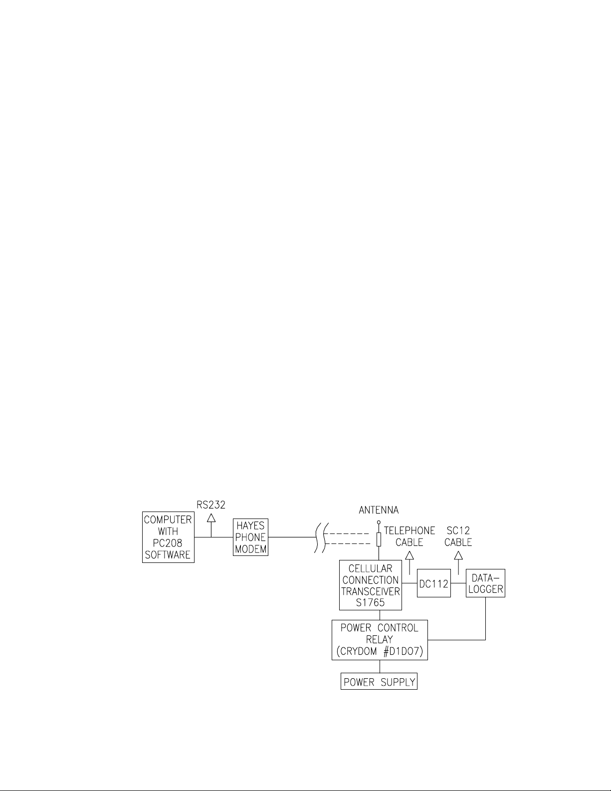
Campbell Scientific's DC1765 Cellular Phone
Package includes:
Motorola S1765 Transceiver
Campbell Scientific DC112 Modem
Crydom Relay D1D07
Mounting bracket and wiring
An appropriate power supply and antenna must
be selected for each station.
The Motorola S1765 Cellular Connection
Transceiver has a standard RJ11C telephone
interface. A standard RJ11C cable connects the
DC112 Modem directly to the transceiver. A
computer equipped with the PC208 Datalogger
Support Software and a Hayes compatible
phone modem connected to a standard phone
line is used to call the cellular equipped stations
(see Figure 1-1).
The transceiver does not have a handset, but if
the user wishes to place a voice call, any
standard touchtone telephone can be
connected. However, the DC112 and a
telephone cannot be connected to the
transceiver at the same time. Programmable
phones will not work with the transceiver.
2. SPECIFICATIONS
S1765 TRANSCEIVER
Dimensions: 2.0 x 3.5 x 8.5 inches
Operating Temperature: -30 to 60 °C
Average current drain
standby: 0.38 A
on line: 2.1 A
Supply voltage: 10.9 - 16.3 VDC
Antenna Termination: Mono UHF
D1D07 RELAY
Control Voltage: 3.5-32.0 VDC
Control Current: <1.6 mA @ 5 VDC
Output Rating: 7 A @ 100 VDC
FIGURE 1-1. Cellular Telecommunications
1
Page 4

DC1765 CELLULAR PHONE PACKAGE
3. ANTENNAS
Each transceiver in a cellular phone system must
have an antenna. Two common types of antennas
are used, omnidirectional and directional. An
omnidirectional antenna transmits and receives in
any direction. A directional antenna transmits and
receives in a particular direction.
Fixed sites are equipped with a directional antenna
because it provides the strongest signal and can be
aimed at a cellular repeater site. There are various
shapes of directional antennas, the most common
being Yagi antennas, such as the ASP962.
Mobile applications use omnidirectional antennas.
Generally, an omnidirectional antenna is a spiraled,
cylindrical rod, mounted vertically. The omni
antennas listed below differ mainly in mounting
hardware.
OMNI ANTENNAS
ASPD1874 Magnetic Mount Antenna
Gain: 3 dB
Frequency: 826-896 MHz
Impedance: 50 ohms
Height: 15"
ASPD910M Trunk Mount Antenna
Gain: 3 dB
Frequency: 806-869 MHz or
824-876 MHz
Bandwidth: 60 MHz @ 1.5:1
75 MHz @ 1.9:1
Impedance: 150 ohms
Height: 24"
ASPD913 Mirror or Side Body Mount Antenna
Gain: 3 dB
Frequency: 824-896 MHz
VSWR Max 1.9:1
Impedance: 50 Ohms
Cable/connector: 17 ft/Mini UHF
ASP955 Vertical Base Station Antenna
Gain: 3 dB
Power: 500 W
Freq: 806-896 MHz
VSWR Max: 1.5:1
Termination: N female
YAGI ANTENNA
ASP962 Broadband Yagi
Gain: 8 dB
Frequency: 806-896 MHz
Bandwidth: 90 MHz
Input Impedance: 50 Ohms
VSWR Max: 1.5:1
Front to Back Ratio: 15 dB
VSWR Max: 1.5:1
Dimensions: 28.5" x 8.25" x 2.5"
Termination N female
4. POWER CONSIDERATIONS
The relay included with the cellular phone
package allows the datalogger to switch power
to the cellular transceiver. Even so, the
relatively high current required by the cellular
transceiver makes it necessary to use a solar
panel, vehicle power system, or AC power to
maintain a charge on the system battery. It is
unfeasible to power the datalogger and
transceiver from batteries alone unless the
battery capacity is very large, the batteries are
changed frequently, or the transceiver is
switched on infrequently.
For fixed site applications without AC power, the
MSX18R Solar Panel is recommended with a
user-supplied deep cycle marine or RV battery.
If the transceiver is seldom on and the site
receives adequate sunlight, a smaller battery
and solar panel may work (see power
calculations).
When AC power is available, The Campbell
Scientific PS12LA power supply may be used to
power the cellular transceiver. The standard
transformer supplied with the PS12LA will only
supply 300 milliamps current. The transceiver
standby power requirement is 380 mA; power to
the transceiver must be switched to avoid
draining the battery. A power budget can be
calculated using the following equation:
(off hook current)*(time off hook) + (on hook
current)*(time on hook) = charge expended
Suppose the transceiver is switched on from
midnight to 1:00 a.m. daily. For one half hour
the transceiver is on hook and for one half hour
the transceiver is off hook. Each day, the
transceiver will drain the battery by:
(2.1 A)(0.5 h) + (0.38 A)(0.5 h) = 1.24 Amphours
A seven Amp-hour battery would be depleted
after 5.65 hours of powering the transceiver, or
5 hours and 38 minutes.
NOTE: When initiating a call from the
datalogger (Instruction 97), the transceiver
must be switched on at least 6 seconds
before the call is placed.
2
Page 5

5. INSTALLATION
DC1765 CELLULAR PHONE PACKAGE
FIGURE 5-1. DC1765 Wiring
6. COMMUNICATION USING PC208
Once consistent cellular coverage has been
established on a stationary phone, interference
should not be a problem. Interference on
mobile phones is more easily encountered. The
local cellular company can verify cellular
coverage of a specific area.
When a transceiver moves, the call may be
transferred from one cell to another. Transceivers
generally stay on-line during these transfers, and
data are transmitted properly. However, if all the
cells are busy or if too much interference occurs,
the call will be dropped. This causes the
transceiver and the DC112 to hang up.
Possible sources of interference that should be
avoided include heavy construction sights,
tunnels, transmitting from the fringes of an area,
and power transmission lines.
6.1 TELCOM
TELCOM checks the signature of each block of
data as it is received from the datalogger. A
poor connection will result in the retransmission
of incorrectly received blocks. If a link is
consistently noisy, use of smaller block size
may improve throughput. If the connection is
completely broken TELCOM will record a
"COMMUNICATION BROKEN WITH
DATALOGGER" error message along with the
time and date of the failure in the error (.ERR)
file. TELCOM keeps track of what data was
successfully collected and will attempt to call
the datalogger to collect the remaining data
based on the retry schedule in the station file
was created.
NOTE: If using a relay to switch power to
the transceiver, make sure retries occur at
times the transceiver is on.
6.2 TERM OR GRAPHTERM
If TERM or GraphTerm is being used in the
Monitor or Graph Mode to view datalogger status,
a poor connection will result in "SEQUENTIAL
INTERRUPT" errors. If several successive
SEQUENTIAL INTERRUPTS occur TERM aborts
monitoring and returns to the Option Menu. This
indicates that the connection is either completely
broken or very poor. If the connection is broken, it
is necessary to call the datalogger again before
monitoring can resume. If communication is poor
or interrupted while downloading a program, the
user should verify that the program was received
correctly and that the datalogger is correctly
logging data.
3
Page 6

DC1765 CELLULAR PHONE PACKAGE
NOTE: When a program is downloaded to
a station that switches power to the
transceiver, communication will be broken
when the program is compiled and all ports
are set low . If the downloaded program
does not include the instructions to switch
on the transceiver, it will be necessary to
visit the site and reprogram the datalogger
before resuming cellular communication.
7. PROGRAMMING TO SWITCH TRANSCEIVER POWER
Switching power to the transceiver allows the
datalogger to maintain a lower power budget by
limiting communication to predetermined times.
The transceiver must be switched on before it
can answer or call.
This section provides examples of datalogger
programming to switch power. If the power
supply is sufficient to power the cellular
transceiver continuously without switching, no
special programming is necessary.
7.1 POWERING ON FIXED INTERVALS
The simplest program switches power on at
specific times and off a fixed time later. This
can be accomplished with two Instructions.
Instruction 92 sets the port controlling the relay
high to turn the power on and a second
Instruction 92 sets the port low. In these
examples, control port 1 controls the relay.
The following program switches the transceiver
on at midnight for 15 minutes:
* 1 Table 1 Programs
01: 10 Sec. Execution Interval
01: P92 If time is
01: 0 minutes into a
02: 1440 minute interval
03: 41 Set high Port 1
02: P92 If time is
01: 15 minutes into a
02: 1440 minute interval
03: 51 Set low Port 1
With the transceiver on for 15 minutes following
midnight, TELCOM would be set to call
automatically once a day at 2 minutes after
midnight. In some areas there are discounts for
calls during off hours.
To allow contacting the station throughout the
day, the transceiver can be turned on for the
first 10 minutes of each hour:
01: P92 If time is
01: 0 minutes into a
02: 60 minute interval
03: 41 Set high Port 1
02: P 92 If time is
01: 10 minutes into a
02: 60 minute interval
03: 51 Set low Port 1
Or one might want to power the transceiver for
one hour at 10 a.m. and at 10 p.m.
01: P 92 If time is
01: 600 minutes into a
02: 720 minute interval
03: 41 Set high Port 1
02: P 92 If time is
01: 660 minutes into a
02: 720 minute interval
03: 51 Set low Port 1
Whatever the time that the program powers the
transceiver, the station must be called while the
transceiver is on; it cannot answer a call at
other times.
7.2 PROGRAM TO ALLOW EXTENDING ON TIME
In the previous examples, communication time
is limited by the program. When the datalogger
switches off the power, communication is
broken and cannot be resumed until the next
time the transceiver is powered. When
monitoring current measurements is important,
the caller must be able to extend the time the
link is active.
The following datalogger program powers the
cellular transceiver for the first 5 minutes of
every half hour. Twenty-five minutes is the
longest one must wait before calling the station.
A 5 minute timer is used to determine when the
transceiver is switched off. Once GT or TERM
has established communication with the station,
the caller can set flag one high (press F1 in the
monitor or graph mode) to restart the timer and
extend the time the link will remain active. The
transceiver is switched off 5 minutes after the
last time flag one is set high.
4
Page 7

* 1 Table 1 Programs
01: 10 Sec. Execution Interval
01: P92 If time is
01: 0 minutes into a
02: 30 minute interval
03: 30 Then Do
02: P86 Do
01: 41 Set high Port 1
03: P18 Time
01: 1 Minutes into current day
02: 0 Mod/by
03: 21 Loc [:START MIN]
04: P95 End
05: P18 Time
01: 1 Minutes into current day
02: 0 Mod/by
03: 22 Loc [:MINinDAY ]
DC1765 CELLULAR PHONE PACKAGE
06: P35 Z=X-Y
01: 22 X Loc MINinDAY
02: 21 Y Loc START MIN
03: 23 Z Loc [:5minTIMER]
07: P89 If X<=>F
01: 23 X Loc 5minTIMER
02: 3 >=
03: 5 F
04: 51 Set low Port 1
08: P91 If Flag/Port
01: 11 Do if flag 1 is high
02: 30 Then Do
09: P18 Time
01: 1 Minutes into current day
02: 0 Mod/by
03: 21 Loc [:START MIN]
10: P86 Do
01: 21 Set low Flag 1
11: P95 End
5
Page 8

Page 9

This is a bla nk page.
Page 10

Campbell Scientific Companies
Campbell Scientific, Inc. (CSI)
815 West 1800 North
Logan, Utah 84321
UNITED STATES
www.campbellsci.com
info@campbellsci.com
Campbell Scientific Africa Pty. Ltd. (CSAf)
PO Box 2450
Somerset West 7129
SOUTH AFRICA
www.csafrica.co.za
sales@csafrica.co.za
Campbell Scientific Australia Pty. Ltd. (CSA)
PO Box 444
Thuringo wa Cent ra l
QLD 4812 AUSTRALIA
www.campbellsci.com.au
info@campbellsci.com.au
Campbell Scientific do Brazil Ltda . (CSB)
Rua Luisa Crapsi Orsi, 15 Butantã
CEP: 005543-000 São Paulo SP BRAZIL
www.campbellsci.com.br
suporte@campbellsci.com.br
Campbell Scientific Canada Corp. (CSC)
11564 - 149th Street NW
Edmonton, Alberta T5M 1W7
CANADA
www.campbellsci.ca
dataloggers@campbellsci.ca
Campbell Scientific Ltd. (CSL)
Campbell Park
80 Hathern Road
Shepshed, Loughborough LE12 9GX
UNITED KINGDOM
www.campbellsci.co.uk
sales@campbellsci.co.uk
Campbell Scientific Ltd. (France)
Miniparc du Verger - Bat. H
1, rue de Terre Neuve - Les Ulis
91967 COURTABOEUF CEDEX
FRANCE
www.campbellsci.fr
campbell.scientific@wanadoo.fr
Campbell Scientific Spain, S. L.
Psg. Font 14, local 8
08013 Barcelona
SPAIN
www.campbellsci.es
info@campbellsci.es
Please visit www.campbellsci.com to obtain contact information for your local US or International representative.
 Loading...