

Page 1
CVS4200 / BVS4300
Stationary Samplers
Revision: 8/13
Copyright © 2011-2013
Campbell Scientific, Inc.
Page 2

Page 3

Warranty
Subject to the following limited warranty, CVS4200 / BVS4300 Stationary
Samplers, with the exception of the refrigerator unit, are warranted for thirtysix (36) months. The refrigerator unit supplied with the CVS4200 / BVS4300
is warranted for twelve (12) months.
“PRODUCTS MANUFACTURED BY CAMPBELL SCIENTIFIC, INC. are
warranted by Campbell Scientific, Inc. (“Campbell”) to be free from defects in
materials and workmanship under normal use and service for twelve (12)
months from date of shipment unless otherwise specified in the corresponding
Campbell pricelist or product manual. Products not manufactured, but that are
re-sold by Campbell, are warranted only to the limits extended by the original
manufacturer. Batteries, fine-wire thermocouples, desiccant, and other
consumables have no warranty. Campbell’s obligation under this warranty is
limited to repairing or replacing (at Campbell’s option) defective products,
which shall be the sole and exclusive remedy under this warranty. The
customer shall assume all costs of removing, reinstalling, and shipping
defective products to Campbell. Campbell will return such products by surface
carrier prepaid within the continental United States of America. To all other
locations, Campbell will return such products best way CIP (Port of Entry)
INCOTERM® 2010, prepaid. This warranty shall not apply to any products
which have been subjected to modification, misuse, neglect, improper service,
accidents of nature, or shipping damage. This warranty is in lieu of all other
warranties, expressed or implied. The warranty for installation services
performed by Campbell such as programming to customer specifications,
electrical connections to products manufactured by Campbell, and product
specific training, is part of Campbell’s product warranty. CAMPBELL
EXPRESSLY DISCLAIMS AND EXCLUDES ANY IMPLIED
WARRANTIES OF MERCHANTABILITY OR FITNESS FOR A
PARTICULAR PURPOSE. Campbell is not liable for any special, indirect,
incidental, and/or consequential damages.”
Page 4

Assistance
Products may not be returned without prior authorization. The following
contact information is for US and international customers residing in countries
served by Campbell Scientific, Inc. directly. Affiliate companies handle
repairs for customers within their territories. Please visit
www.campbellsci.com to determine which Campbell Scientific company serves
your country.
To obtain a Returned Materials Authorization (RMA), contact CAMPBELL
SCIENTIFIC, INC., phone (435) 227-9000. After an applications engineer
determines the nature of the problem, an RMA number will be issued. Please
write this number clearly on the outside of the shipping container. Campbell
Scientific’s shipping address is:
CAMPBELL SCIENTIFIC, INC.
RMA#_____
815 West 1800 North
Logan, Utah 84321-1784
For all returns, the customer must fill out a “Statement of Product Cleanliness
and Decontamination” form and comply with the requirements specified in it.
The form is available from our web site at www.campbellsci.com/repair. A
completed form must be either emailed to repair@campbellsci.com or faxed to
(435) 227-9106. Campbell Scientific is unable to process any returns until we
receive this form. If the form is not received within three days of product
receipt or is incomplete, the product will be returned to the customer at the
customer’s expense. Campbell Scientific reserves the right to refuse service on
products that were exposed to contaminants that may cause health or safety
concerns for our employees.
Page 5

Table of Contents
PDF viewers: These page numbers refer to the printed version of this document. Use the
PDF reader bookmarks tab for links to specific sections.
1. Introduction.................................................................1
2. Cautionary Statements...............................................1
3. Initial Inspection .........................................................2
4. Quickstart .................................................................... 2
4.1 Cabinet Positioning ..............................................................................2
4.2 Attach Intake Hose...............................................................................3
4.3 Wiring ..................................................................................................4
4.3.1 CVS4200 Wiring Procedure .........................................................4
4.3.2 BVS4300 Wiring Procedure .........................................................5
4.4 Program the Sampler............................................................................5
4.4.1 Automatic Sampling Program.......................................................5
4.4.2 Taking a Manual Sample ..............................................................6
4.4.3 Viewing Program Parameters .......................................................7
4.4.4 Setting Programming Parameters Individually .............................7
4.5 Installation Checklist............................................................................7
5. Product Overview .......................................................7
5.1 Components .........................................................................................9
5.1.1 BVS4300 Sampler Components ...................................................9
5.1.2 CVS4200 Sampler Components .................................................11
5.1.3 Sampler Vacuum System Components.......................................13
5.2 Sample Container Options .................................................................15
5.3 Discrete and Composite Overview.....................................................15
5.3.1 Discrete Sampling.......................................................................15
5.3.2 Composite Sampling...................................................................16
5.4 Sinker / Strainer..................................................................................16
5.5 Special Systems..................................................................................17
5.5.1 5/8 in. Systems............................................................................17
5.5.2 Sanitary Systems – Teflon and Glass..........................................17
5.5.3 Pressurized Source......................................................................18
6. Specifications ...........................................................20
6.1 BVS4300 Outdoor Stationary Sampler Specifications.......................21
6.2 CVS4200 Indoor Stationary Sampler Specifications .........................22
6.3 Controller Specifications....................................................................22
6.4 Vacuum System Specifications..........................................................24
6.5 Sample Transport Velocity.................................................................24
6.5.1 Using Velocity to Calculate Purge Time.....................................26
6.5.2 Horizontal/Vertical Combinations ..............................................26
i
Page 6

Table of Contents
7. Operation ...................................................................26
7.1 Use in Adverse Conditions................................................................ 26
7.1.1 Exhaust....................................................................................... 26
7.1.2 Instrument Air ............................................................................ 26
7.1.3 Freezing Conditions ................................................................... 27
7.2 Power Line/Wiring Considerations ................................................... 27
7.3 Operating Sequence........................................................................... 28
7.3.1 Sampling Sequence .................................................................... 28
7.3.2 Line Voltage Failure................................................................... 29
7.4 Operating Instructions ....................................................................... 29
7.4.1 Sample Volume Adjustments..................................................... 29
7.4.2 Liquid Sensing Rod.................................................................... 30
7.5 Battery ............................................................................................... 30
7.5.1 Charging 12 Vdc Battery and Reverse Polarity Protection ........ 30
7.5.2 Sampler Controller Backup Battery ........................................... 31
7.6 Programming..................................................................................... 32
7.6.1 Guidelines .................................................................................. 32
7.6.1.1 Flashing Text................................................................... 32
7.6.1.2 Real Time Clock.............................................................. 32
7.6.1.3 Total Bottles .................................................................... 32
7.6.2 Touchpad Keys........................................................................... 33
7.6.3 General Terms............................................................................ 35
7.6.4 Programming START DELAY.................................................. 37
7.6.4.1 START DELAY Overview ............................................. 37
7.6.4.2 START DELAY using Time/Day ................................... 38
7.6.4.3 START DELAY using Pulse Input ................................. 40
7.6.4.4 START DELAY using 4-20mA Input............................. 41
7.6.4.5 START DELAY using External Contact......................... 43
7.6.4.6 START DELAY using Level Control ............................. 43
7.6.5 Programming SAMPLE INITIATION....................................... 45
7.6.5.1 SAMPLE INITIATION Overview.................................. 45
7.6.5.2 SAMPLE INITIATION using Interval Time .................. 46
7.6.5.3 SAMPLE INITIATION using Pulse Input...................... 47
7.6.5.4 SAMPLE INITIATION using 4-20mA Input.................. 49
7.6.5.5 SAMPLE INITIATION using External Contact ............. 50
7.6.6 Programming PROGRAM TYPE .............................................. 51
7.6.6.1 PROGRAM TYPE Overview.......................................... 51
7.6.6.2 PROGRAM TYPE - Composite...................................... 52
7.6.6.3 PROGRAM TYPE - Daily Cycle.................................... 54
7.6.6.4 PROGRAM TYPE - Daily Cycle for Dual Station ......... 55
7.6.6.5 PROGRAM TYPE - Consecutive ................................... 57
7.6.6.6 PROGRAM TYPE - Multi-Composite............................ 59
7.6.6.7 PROGRAM TYPE - Timed Step..................................... 60
7.6.7 Programming OTHER OPTIONS.............................................. 62
7.6.7.1 OTHER OPTIONS Overview ......................................... 62
7.6.7.2 OTHER OPTIONS - Clock ............................................. 64
7.6.7.3 OTHER OPTIONS - Purge Time.................................... 65
7.6.7.4 OTHER OPTIONS - Pinch Valve................................... 67
7.6.7.5 OTHER OPTIONS - Fault Shutdown ............................. 68
7.6.8 Viewing Information .................................................................. 69
7.6.8.1 Viewing Programmed Information.................................. 69
7.6.8.2 Viewing Generated Information...................................... 72
7.7 Test Procedure................................................................................... 73
ii
Page 7

Table of Contents
8. Troubleshooting........................................................73
9. Maintenance ..............................................................74
9.1 General Maintenance .........................................................................74
9.2 Maintenance of Refrigerator ..............................................................75
9.2.1 Cleaning ......................................................................................75
9.2.2 Temperature Control...................................................................75
9.3 Testing System Vacuum ....................................................................76
9.4 Controller Battery Repalcement Procedure........................................76
9.5 Storage ...............................................................................................76
Appendices
A.
Principles of Operation .......................................... A-1
B. Parts List ................................................................. B-1
Figures
Tables
4-1. Sampler installation..............................................................................3
4-2. Terminal block wiring diagram............................................................4
5-1. Diagrams of the BVS4300 basic unit...................................................9
5-2. Diagrams of the CVS4200 basic unit.................................................11
5-3. Diagram of the CVS/BVS vacuum system ........................................13
5-4. Discrete removable bottle tray (24 bottles) ........................................16
5-5. Composite two gallon bottle with lid .................................................16
5-6. Lead sinker.........................................................................................17
5-7. Stainless-steel sinker/strainer .............................................................17
5-8. Vertical loop for pressurized source...................................................18
5-9. Flow-through chamber for pressurized source...................................19
7-1. Battery performance curve.................................................................31
5-1. BVS4300 Component Descriptions ...................................................10
5-2. CVS4200 Sampler Component Descriptions.....................................12
5-3. Vacuum System Component Descriptions.........................................14
5-4. Sample Container Options .................................................................15
5-5. Sanitary System Changes...................................................................18
6-1. BVS4300 Sampler Specifications ......................................................21
6-2. CVS4200 Sampler Specifications ......................................................22
6-3. Controller Specifications....................................................................22
6-4. Controller Specifications....................................................................23
6-5. Vacuum System Specifications..........................................................24
6-6. Vertical Velocity ................................................................................24
6-7. Horizontal Lift....................................................................................25
7-1. Touchpad Button Descriptions...........................................................33
B-1. CVS/BVS Replacement Parts ..........................................................B-1
iii
Page 8

Table of Contents
iv
Page 9

CVS4200 / BVS4300 Stationary
Samplers
1. Introduction
The CVS4200-series and BVS4300-series Stationary Samplers are automatic
liquid samplers for water and wastewater applications. They use reliable, longlasting, vacuum technology. This sampling method results in faster sample
draws and less disturbance of the sample contents. There is also less wear on
the tubing, resulting in less-frequent maintenance.
Campbell Scientific offers the following stationary samplers:
• CVS4200C—composite indoor sampler
• CVS4200D—discrete indoor sampler
• BVS4300C—composite outdoor sampler
• BVS4300D—discrete outdoor sampler
Composite samplers deposit all samples into a single container. Discrete
samplers place each sample into a separate container.
Before installing the water sampler, please study:
• Section 2, Cautionary Statements
• Section 3, Initial Inspection
• Section 4, Quickstart
2. Cautionary Statements
• A noise free or clean line from primary power is highly recommended to
supply the sampler.
• Never run the sampler’s power wiring in conduit containing phone lines or
power wiring of other devices.
• If possible, site the sampler away from ac power lines.
• Use a BVS4300 with a factory installed heater (option -H) and an
insulated cabinet (option -3) if the sampler will be located outdoors in
freezing conditions. Refer to Section 7.1, Use in Adverse Conditions, for
more information.
• In extreme cold conditions, insulate or heat the intake hose. If the hose is
positioned mostly vertical, the most prone point of freezing is where the
hose enters the frozen water source.
• Use a BVS4300 with the cabinet circulation fan (option -G) if the sampler
will be placed directly in the sun. This keeps the refrigeration unit from
getting overtaxed.
1
Page 10

CVS4200 / BVS4300 Stationary Samplers
• The intake hose should be 7.6 m (25 ft) or longer. Shorter hoses do not
provide sufficient back pressure to the metering chamber, allowing the
pump to efficiently expel all solids into the sampler container.
• Under adverse atmospheric conditions (humid, corrosive, etc.), connect air
to the BVS4300 and use it to purge the cabinet—providing clean air for
the pump intake.
CAUTION
Failure to purge the cabinet may damage the sampler and
void the warranty (see Section 7.1, Use in Adverse
Conditions, for more information).
• Vent the exhaust outdoors if detrimental air conditions exist in the sample
lines of a CVS4200 sampler (see Section 7.1, Use in Adverse Conditions,
for more information).
3. Initial Inspection
• Upon receipt of the CVS4200 or BVS4300, inspect the packaging and
contents for damage. File damage claims with the shipping company.
• Immediately check package contents against the shipping documentation.
Contact Campbell Scientific about any discrepancies.
4. Quickstart
Please refer to Section 7.1, Use in Adverse Conditions, if the sampler is used
under adverse atmospheric conditions such as extreme humidity.
4.1 Cabinet Positioning
2
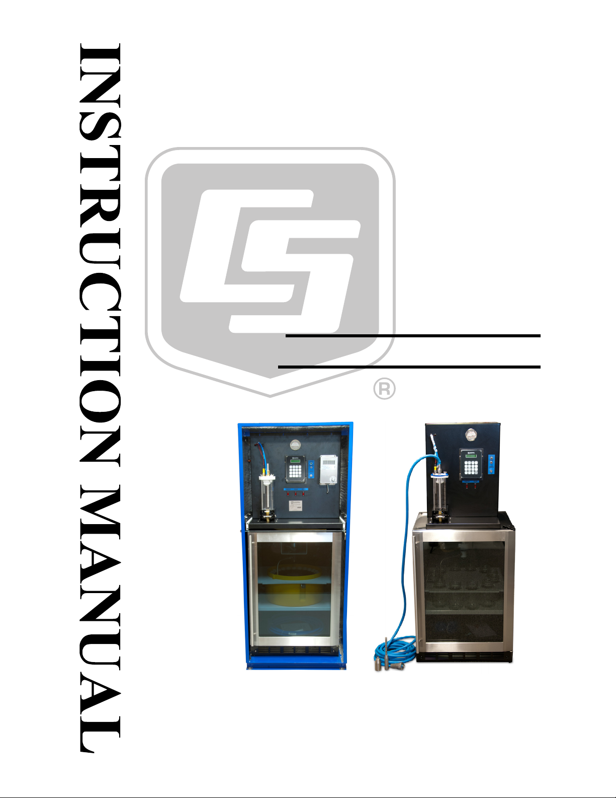
NOTE
Install the sampler as close as possible to the sampling site with a minimum of
10 cm (4 in) of air space around the cabinet (see FIGURE 4-1). Level and
secure the unit.
Sampler must be located above sample source, or liquid will
flood the machine. For situations where this is not possible,
please contact a Campbell Scientific applications engineer for
solutions on pressurized sources.
Page 11
CVS4200 / BVS4300 Stationary Samplers
FIGURE 4-1. Sampler installation
4.2 Attach Intake Hose
1. Connect the intake hose to the sampler’s volume control tube (item 1 in
FIGURE 5-1 or FIGURE 5-2).
a. If using the 26925-L PVC Intake Hose with option -QD, attach the
hose using the quick deploy connector.
b. Otherwise, place the hose in warm water for a few minutes. Slip the
hose over the volume control tube and secure the hose using the
clamp.
2. Route the hose so that it has a near continuous slope from the sampler to
the source liquid. This keeps hose clear and fully drained.
3. Place sinker/strainer in source liquid. The sinker/strainer needs to be
placed at a depth in which it will remain submerged regardless of the flow
velocities.
3
Page 12
CVS4200 / BVS4300 Stationary Samplers
4.3 Wiring
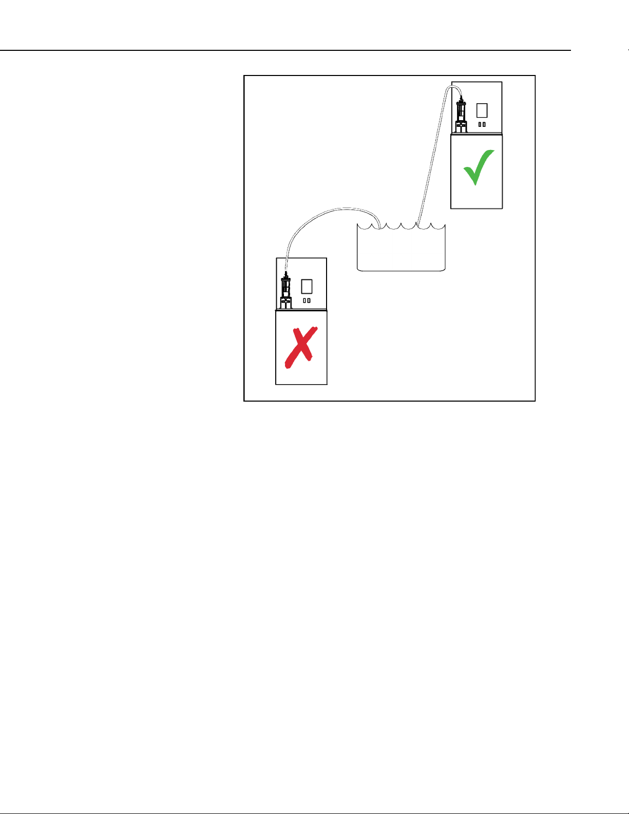
FIGURE 4-2. Terminal block wiring diagram
4.3.1 CVS4200 Wiring Procedure
1. Remove the hood from chassis. The terminals for field connections are
located along the back of the tray (11 on FIGURE 5-2). If the sampler has
been provided with a refrigerator, the power plug is also located here.
2. Route cabling from external devices through the clearance holes and
connect to the terminal block (see FIGURE 4-2).
NOTE
Use shielded cables for wiring remote/external functions and
terminate the shield at the AC ground terminal on the sampler
main terminal block, or at the remote site, but not both.
3. Bring power from main distribution panel along a path that does not
parallel any existing power wiring to motors, solenoids, or contactors.
When sampler power line must cross existing power lines, do so at right
angles.
4. Replace hood.
4
Page 13
4.3.2 BVS4300 Wiring Procedure
1. Remove four retaining bolts (1/4–20) found across the top of the
instrument panel (18 in FIGURE 5-1).
2. If the sampler is refrigerated, make sure the discharge tubing and container
full wiring (if so equipped) are extracted from the fridge.
3. Slide out instrument section. The drawer glides that the sampler chassis is
mounted on are designed to fully extend from the cabinet.
4. Route cabling from external devices through the 2.75 inch conduit knockouts and connect to the terminal block (see FIGURE 4-2). The terminals
for field connection are located along the side at the rear of the tray.
CVS4200 / BVS4300 Stationary Samplers
NOTE
Use shielded cables for wiring remote/external functions and
terminate the shield at the AC ground terminal on the sampler
main terminal block, or at the remote site, but not both.
5. Bring power from main distribution panel along a path that does not
parallel any existing power wiring to motors, solenoids, or contactors.
When sampler power lines must cross existing power lines, do so at right
angles.
6. Ensure that the wiring harness will not rub or catch in the slide
mechanisms before sliding the instrument section back into the cabinet.
7. Replace the four retaining bolts. Although not required for operation, use
of these retaining bolts reduces the effects of vibration that occur when the
sampler is cycling.
4.4 Program the Sampler
4.4.1 Automatic Sampling Program
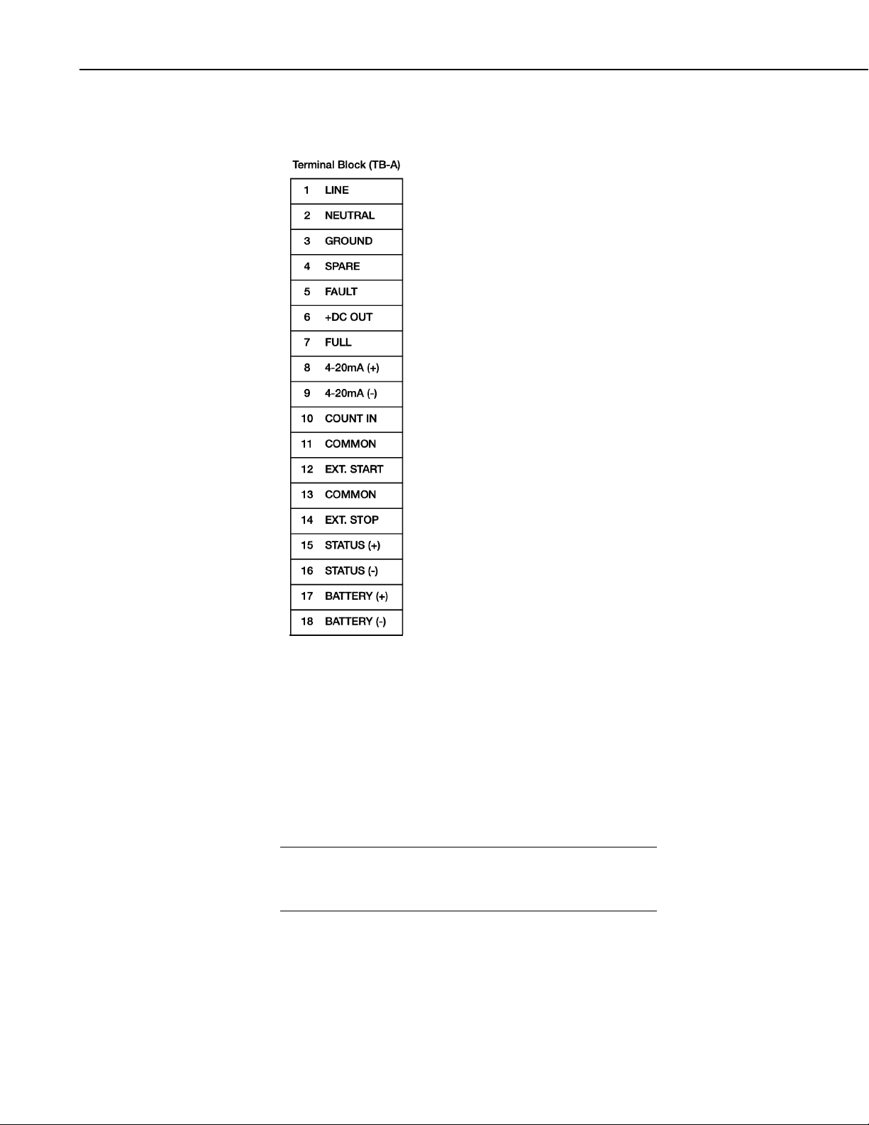
To begin a new, quick program:
Press “SET”
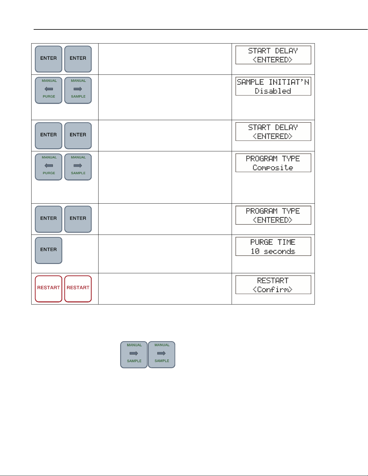
Press “NEW ENTRIES”. Press “ENTER”
START DELAY (how you will be delaying the
sample program until certain external conditions are
met). Select, using arrows, which parameter you
would like, and adjust settings (see Section 7.6.4,
Programming START DELAY). Options: DISABLE;
TIME/DAY; PULSE INPUT; 4-20mA INPUT;
EXTERNAL CONTACT; LEVEL CONTROL.
5
Page 14
CVS4200 / BVS4300 Stationary Samplers
Press “ENTER” twice
SAMPLE INITIATION (parameters for frequency
of samples). Select, using arrows, which parameter
you would like, and adjust settings (see Section
7.6.5, Programming SAMPLE INITIATION).
Options: DISABLE; INTERVAL TIME; PULSE
INPUT; 4-20mA INPUT; EXTERNAL CONTACT.
Press “ENTER” twice.
PROGRAM TYPE (which type of sampling
program). Select, using arrows, which parameter
you would like, and adjust settings (see Section
7.6.6, Programming PROGRAM TYPE). Options:
COMPOSITE; MULTI-COMPOSITE;
CONSECUTIVE; DAILY CYCLE; TIMED STEP
(override).
Press “ENTER” twice.
PURGE TIME (set how long sampler will purge
between samples, minimum of 10 seconds). Using #
keys, enter the purge time needed for application
(e.g., 100 ft draw at 5 ft/sec = 20 sec). Press
“ENTER”.
Press “RESTART” twice.
Sampling is ready to go.
4.4.2 Taking a Manual Sample
To take a sample manually, simply press the
“Manual Sample” button twice. Manual
samples will not interrupt the current
automatic sampling program.
6
Page 15

CVS4200 / BVS4300 Stationary Samplers
4.4.3 Viewing Program Parameters
To view the program or remaining time,
press the “VIEW” button, followed by the
button representing what you want to see;
for example, “REMAINING TIME”.
4.4.4 Setting Programming Parameters Individually
To modify any of the settings individually,
press the “SET” button followed by the
appropriate button based on what parameter
is being changed.
4.5 Installation Checklist
Check the following items prior to use of sampler:
1) Sampler is mounted securely and level.
2) Intake Hose: – Free of kinks.
– Properly installed into liquid.
– Properly connected to volume control tube on
metering chamber.
3) Discharge hose: – Free of kinks.
– Natural downward slope to sample container.
– Properly connected to (or in) sample container.
4) Proper exhaust and instrument air connections (see Section 7.1, Use in
Adverse Conditions).
5) Power requirements: – Check terminal strip connections.
– Test all outside sources of sampler controls.
5. Product Overview
The BVS4300 and CVS4200 Stationary Samplers are automatic liquid
samplers for water and wastewater applications. CVS/BVS Samplers are
capable of gathering fluid automatically from a variety of sources, including
containers, open channels, sewers, pipes, and any open source of water.
Samplers are designed for reliable, unattended sample collection. Refrigerated
units will keep the temperature of the deposited liquid at 4ºC (39.2ºF) until the
samples are gathered and brought back to the laboratory for analysis.
There are a variety of methods for depositing samples. Composite sampling is
used where samples are deposited, over time, into one container. Discrete
systems are used when multiple bottles are needed. These are also called
“sequential” systems, and involve a stepper with distributor arm which
dispenses the liquid into a bottle, then moves to the next bottle.
7
Page 16

CVS4200 / BVS4300 Stationary Samplers
Operating temperature for CVS4200 indoor samplers is 10º to 50ºC (50º to
122ºF), adaptable down to 0ºC (32ºF) upon request. The operating temperature
for BVS4300 outdoor samplers with heater and insulation is –40º to 50ºC (–40º
to 122ºF). Without insulation and heater, the BVS4300 operating temperature
is 0º to 50ºC (32º to 122ºF).
Samples can be triggered by a variety of means. The internal clock on the
controller can be set to sample based on time/day (for example, sample every
hour). There are also a variety of external inputs that can be connected to
control sampling. Pulse count is useful for sampling after a certain number of
pulses have been reached (for example, using a rain gauge to trigger sampling).
The 4-20mA option is useful for flow-based sampling (for example, using a
flow meter to trigger sampling after a certain volume of water has passed by).
External contact is used to control the sampler from another datalogger, and is
useful when full external control is desired. Level control is the option to
choose when the application has starts and stops (for example, using a float
switch to trigger sampling when water is present, then stop sampling when the
water drops below the set level).
When sampling is initiated, liquid travels through the intake tube into the
metering chamber. The amount of water taken is set mechanically using the
liquid sensing rod and the volume control tube, which means sample accuracy
is precise every time, usually within ±2% or ±2 ml.
Once the pre-set amount has been reached, all excess liquid is purged from the
system, and the sample is dropped into a container. Sample containers range
from 500 ml (500 cc or 2 cups) wedges in discrete systems, up to 20 liters (5
gallons) containers for composite systems.
Intake tube is offered in either 9.5 mm (3/8 in) ID or 15.9 mm (5/8 in) ID.
Transport velocity varies depending on height and distance being sampled. For
most situations the sampler pulls at over 1.5 m s
–1
(5 ft s–1). For an in-depth
speed chart, refer to Section 6.5, Sample Transport Velocity.
8
Page 17
5.1 Components .1 Components
5.1.1 BVS4300 Sampler Components 5.1.1 BVS4300 Sampler Components
63.0”
(1600 mm)
CVS4200 / BVS4300 Stationary Samplers
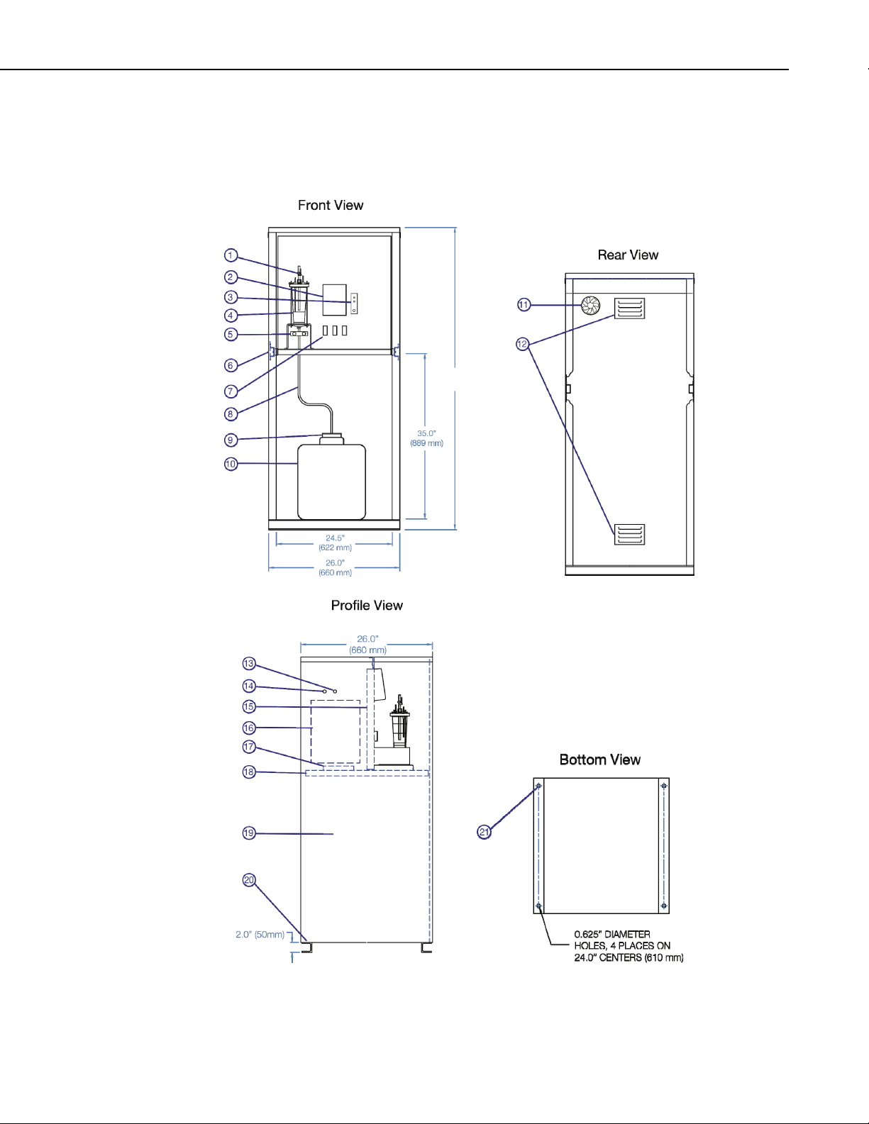
FIGURE 5-1. Diagrams of the BVS4300 basic unit
9
Page 18

CVS4200 / BVS4300 Stationary Samplers
TABLE 5-1. BVS4300 Component Descriptions
Number Item Description
1 Intake Hose Connection The volume control tube is where the intake hose is connected to
the sampler. This stainless steel tube is raised or lowered
manually using fitting to set the sample volume (see FIGURE
5-3).
2 Multi-Function Input Controller This is where sampler is controlled and programmed.
3 Signal Lights and Control
Switch
The optional top light (green) indicates sampler is running. The
second light (red) indicates reverse polarity if external battery is
being used. The toggle switch turns on/off the controller while
leaving power to the sampler.
4 Metering Chamber This chamber is where the sample liquid is drawn into before
dropping into the final container. The rods inside are raised and
lowered to the sample volume desired.
5 Pinch Valve This valve shuts during sampling, and then releases once desired
liquid has entered the chamber.
6 Instrument Tray Rollers Control section of sampler can be easily rolled out for wiring and
maintenance.
7 Breaker Switches All samplers have an on/off switch. Other options for switches
include fridge and heater.
8 Discharge Tube The sample liquid is released via the pinch valve to the sample
container(s) below. With composite (single container) units the
amount of built-up pressure may cause discharge tube to come
out of the container, so it is advisable to fasten it using the
provided lid.
9 Container Lid The special lid provided fastens the discharge tube to the sample
container. Weight prevents tube dislocation.
10 Sample Container(s) The container(s) that the sample is deposited in can be made
from a variety of materials, shapes, and sizes. In discrete
samplers, there is a distributor arm that deposits samples into
multiple containers.
11 Cabinet Circulation Fan Optional fan for hot weather climates, prolongs the life of
refrigerator. If no fan is present, this space will be solid.
12 Louvers Vents for ensuring proper ventilation in cabinet.
13 Pump Exhaust Connection If the sample fluid is corrosive, the pump exhaust air can be sent
to a separate location through this connector; unnecessary in
most conditions.
14 Instrument Air Connection In corrosive environments, instrument air can be brought in from
another source, prolonging the life of the instrumentation
components. Tubing would be hooked up to the provided
adapter. This is unnecessary in most environments.
15 Instrument Panel Instrumentation is mounted on this panel.
16 Instrumentation Section All instrumentation and wiring, including pump, are located in
this section of the sampler, protected from outside elements.
17 Field Wiring Terminals Terminal block for field wiring is located on the back of the
instrument tray
18 Instrument Tray This tray can be rolled out by unscrewing the four bolts at the top
of the panel, and gliding it out on the rollers.
19 Enclosure Cabinet for entire sampler is powder-coated steel or optional
stainless steel.
20 Mounting Feet Brackets have holes for screwing sampler into a fixed location.
21 Installation Holes Put bolts through these holes into a solid surface to stabilize
sampler.
10
Page 19
5.1.2 CVS4200 Sampler Components
CVS4200 / BVS4300 Stationary Samplers
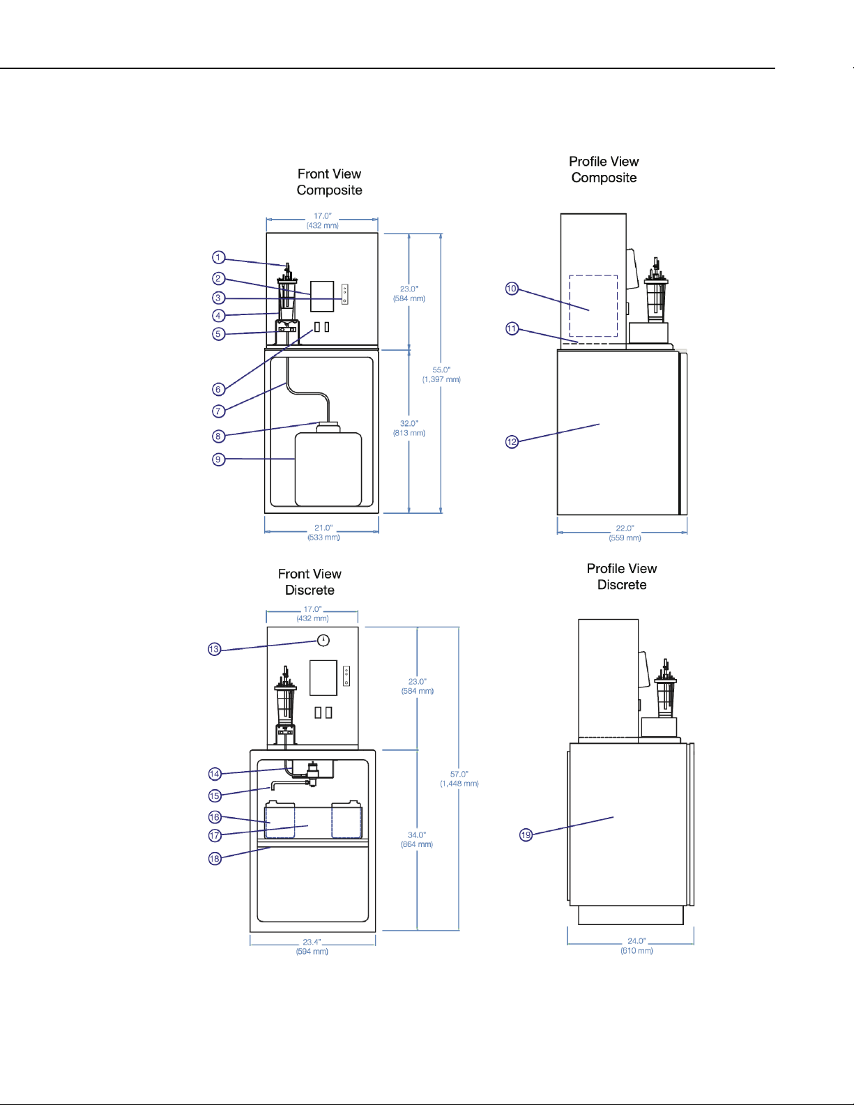
FIGURE 5-2. Diagrams of the CVS4200 basic unit
11
Page 20

CVS4200 / BVS4300 Stationary Samplers
TABLE 5-2. CVS4200 Sampler Component Descriptions
Number Item Description
1 Intake Hose Connection
The volume control tube is where the intake hose is connected to
the sampler. This stainless steel tube is raised or lowered
manually using fitting to set the sample volume (see FIGURE
5-3).
2 Multi-Function Input Controller This is where sampler is controlled and programmed.
3
Signal Lights and Control
Switch
The optional top light (green) indicates sampler is running. The
second light (red) indicates reverse polarity if external battery is
being used. The toggle switch turns on/off the controller while
leaving power to the sampler.
4 Metering Chamber
This chamber is where the sample liquid is drawn into before
dropping into the final container. The rods inside are raised and
lowered to the sample volume desired.
5 Pinch Valve
This valve shuts during sampling, and then releases once desired
liquid has entered the chamber.
6 Breaker Switches
All samplers have an on/off switch. Other option for switch is for
fridge.
7 Discharge Tube
The sample liquid is released via the pinch valve to the sample
container(s) below. With composite (single container) units the
amount of built-up pressure may cause discharge tube to come
out of the container, so it is advisable to fasten it using the
provided lid.
8 Container Lid
The special lid provided fastens the discharge tube to the sample
container. Weight prevents tube dislocation.
9 Sample Container
The container that the sample is deposited into can be made from
a variety of materials, shapes, and sizes. Standard bottles are 2 or
5 gallon high density polyethylene (HDPE).
10 Instrumentation Section
All instrumentation and wiring, including pump, are located in
this section of the sampler, protected from outside elements.
11 Field Wiring Terminals
Terminal block for field wiring is located on the back of the
instrument tray
12 Refrigerator – Small Composite samplers have a smaller refrigerator by default.
13 Pressure Gauge
Optional pressure gauge is useful for monitoring
vacuum/pressure status, i.e. for checking plugged lines and
discovering leaks.
14 Stepper Motor and Bracket
Installed directly onto roof of refrigerator, this bracket is lined up
to deliver samples uniformly to multiple bottles. The stepper
moves the distributor arm after sampling the previous bottle.
15 Distributor Arm Stainless steel arm delivers liquid samples to the discrete bottles.
16 Discrete Bottles
Diagram shows 24 wedge bottle arrangement. Any arrangement
of bottles is possible that is factors of 24 and fits inside the
limited space (for example, 2 x 2 gallon containers).
17 Removable Bottle Tray
Some arrangements include a removable tray with handles for
easy swapping of bottles (24 bottle and 8 bottle options only).
18 Bottle Seating Template
With removable bottle tray, a circular guide and bolt lock holds
tray in its precise location. With other bottle arrangements, the
template includes seating guides for each bottle individually.
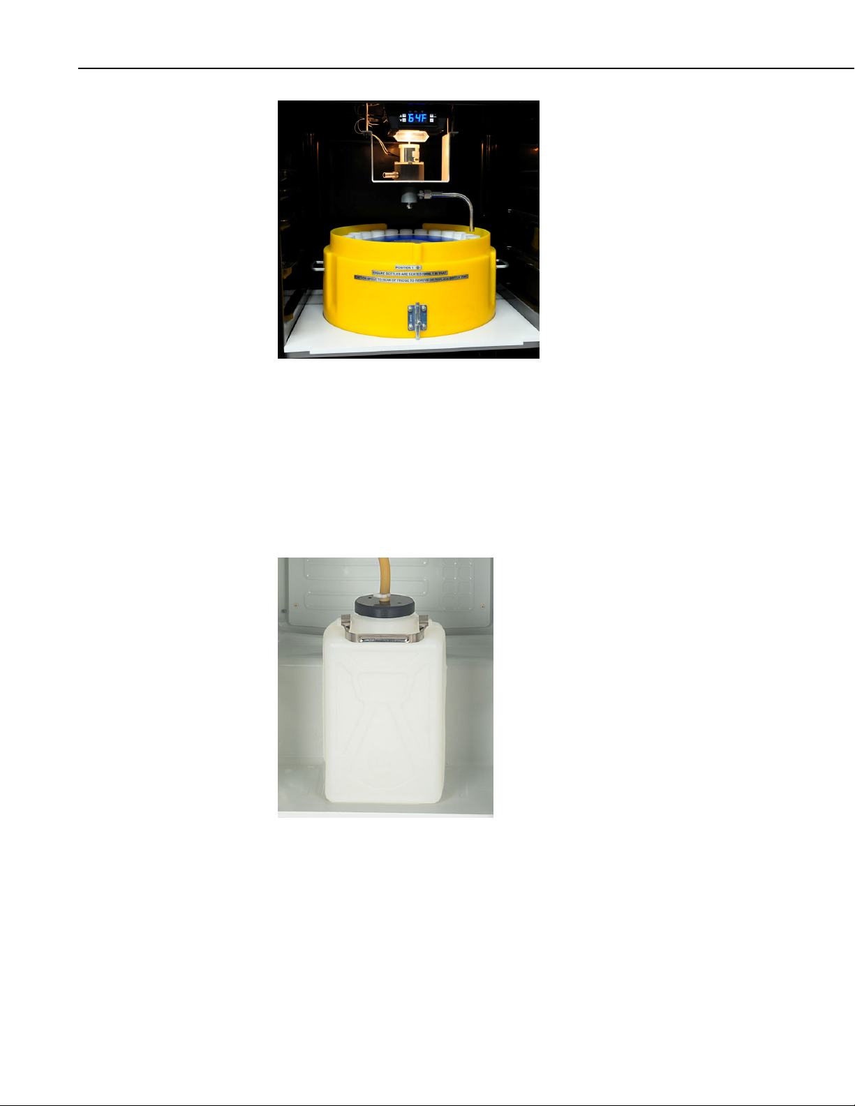
19 Refrigerator - Large
Discrete samplers have a large glass-door refrigerator with digital
thermostat display.
12
Page 21
CVS4200 / BVS4300 Stationary Samplers
5.1.3 Sampler Vacuum System Components
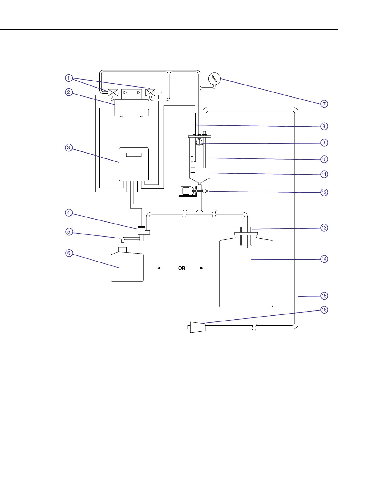
FIGURE 5-3. Diagram of the CVS/BVS vacuum system
13
Page 22

CVS4200 / BVS4300 Stationary Samplers
TABLE 5-3. Vacuum System Component Descriptions
Number Item Description
1 Solenoid Valves Control the air flow from pump to sampler, either purging or
sucking.
2 Pump Located behind a sheet of metal, the pump does not come into
contact with any liquid whatsoever. It does all the drawing and
purging through using a vacuum and compressor.
3 Touchpad Controller Controls sampler program and offers status feedback on LCD.
4 Sample Distributor Rotates distributor arm between multiple discrete containers.
5 Distributor Arm Dispenses liquid from metering chamber into discrete container.
6 Discrete Sample Containers Multiple containers. Any arrangement of bottles is possible that
is factors of 24 and fits inside the 5 ft
3
refrigeration unit.
7 Pressure Gauge Visually describes sampling process in terms of
vacuum/pressure. Useful for troubleshooting a plugged/kinked
line, or signals leaks. Optional.
8 Liquid Sensing Rod This rod must remain above the volume control tube. When the
sample liquid comes into contact with the two rods, it signals
the controller to stop sampling and begin purging.
9 Barrier Valve Prevents metering chamber overflow in case the liquid sensing
rod fails (for example, completely coated with oils/grease).
10 Volume Control Tube Mechanically set the volume required for sample by using a
wrench on the fitting at the base of this stainless steel tube.
11 Metering Chamber Sample is drawn into chamber up to level set by volume control
tube, then line is purged, followed by dropping sample into
containers. Metering Chambers come in glass or acrylic, from
250 cc to 1,000 cc.
12 Pinch Valve This valve shuts during sampling, then opens during sampling to
drop sample into container, then closes to purge hose.
13 Cap with “Container Full” Shut-
off
Optional cap contains Overflow Protection Probes which signal
the sampler to halt when container is full. Can be installed in
maximum two containers, or into a discrete bottle tray.
14 Composite Sample Container A single container to hold sample liquid. Can be used with
smaller refrigerator.
15 Intake Hose Standard samplers come with 7.6 m (25 ft) of 3/8 inch ID PVC
tube.
16 Sinker. Optional Strainer. Keeps the end of the intake tube in the source liquid. Optional
strainer can raise collection point above sinker.
14
Page 23

5.2 Sample Container Options
TABLE 5-4. Sample Container Options
Feature Description
CVS4200 / BVS4300 Stationary Samplers
Composite (single)
containers
Discrete (multiple)
containers
9 liter (2.3 US gallon) Nalgene
9 liter (2.3 US gallon) Nalgene with overflow
20 liter (5 US gallon) Nalgene
20 liter (5 US gallon) Nalgene with overflow
10 liter (2.5 US gallon) Glass
10 liter (2.5 US gallon) Glass with overflow
0.5 liter Plastic [24 bottles]
1 liter Glass [12 bottles]
2 liter Glass [8 bottles]
4 liter Glass [4 bottles]
10 liter (2.5 US gallon) Glass [with and without
overflow]
9 liter (2.3 US gallon) Nalgene
9 liter (2.3 US gallon) Nalgene with overflow
20 liter (5 US gallon) Nalgene
20 liter (5 US gallon) Nalgene with overflow
5.3 Discrete and Composite Overview
5.3.1 Discrete Sampling
Discrete sampling is sampling wherein samples are taken into more than one
container. Inside of the refrigerator (or cooling chamber on portable sampler
units) is a stepper assembly which revolves 360° and delivers samples into
separate containers, ranging from 2 to 24 bottles. Discrete sampling is
beneficial in situations where change over time needs to be measured, such as
measuring different water characteristics over 24 hours. Labs and monitoring
personnel tend to rely on discrete portable sampling.
15
Page 24
CVS4200 / BVS4300 Stationary Samplers
FIGURE 5-4. Discrete removable bottle tray (24 bottles)
5.3.2 Composite Sampling
Composite sampling is for drawing water samples into one large container.
This is the simplest way of taking samples and typical for most situations
where a sampler is set up to measure effluent in one location. It is also
significantly less expensive than discrete sampling.
16
FIGURE 5-5. Composite two gallon bottle with lid
5.4 Sinker / Strainer
The intake hose includes either a lead sinker or stainless-steel sinker/strainer.
The sinker or sinker/strainer is intended to keep the sample line fully
submerged in the source liquid. The stainless-steel sinker/strainer should be
used in samples with material that may clog up a normal sinker, or where the
standard sinker could stir up bottom sediment.
Page 25
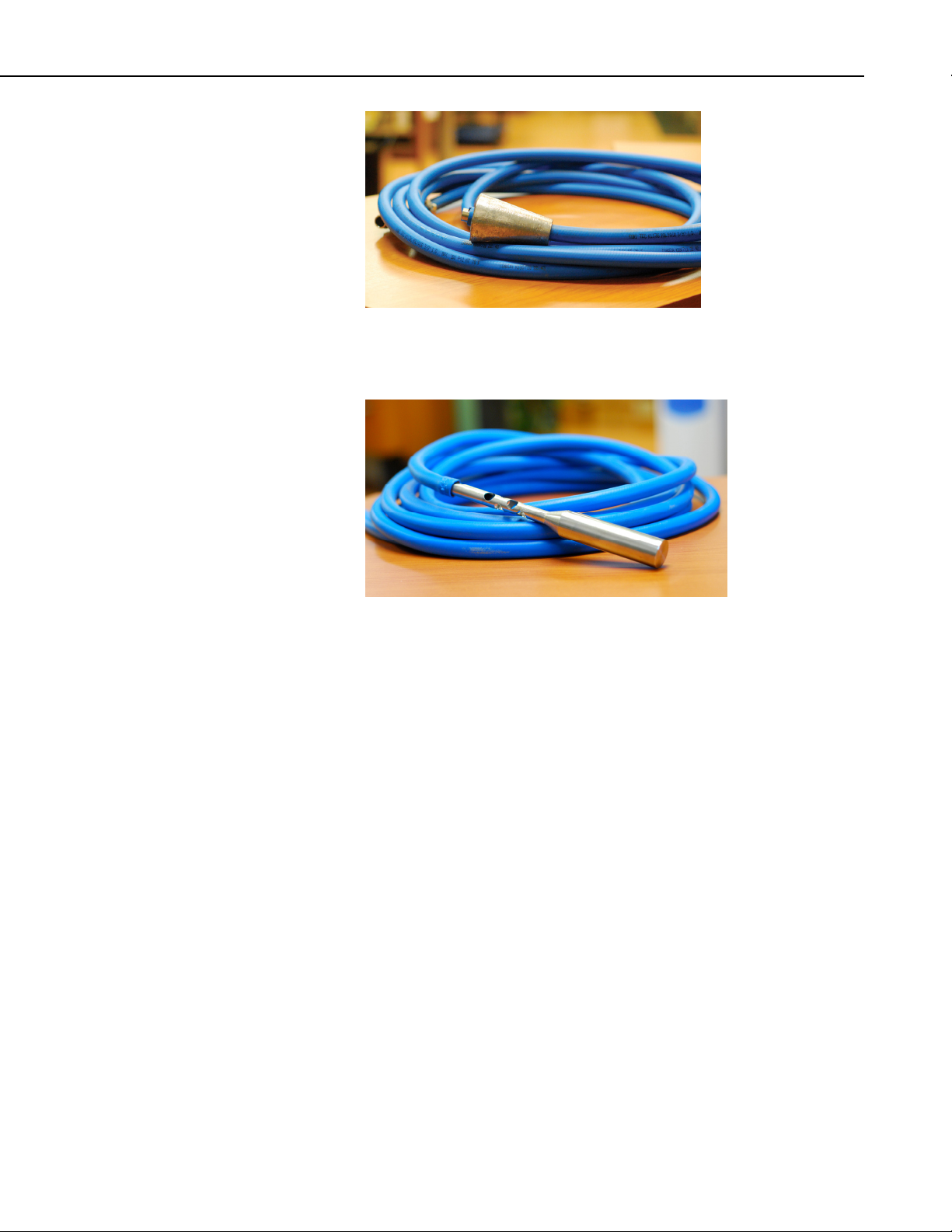
FIGURE 5-6. Lead sinker
CVS4200 / BVS4300 Stationary Samplers
FIGURE 5-7. Stainless-steel sinker/strainer
5.5 Special Systems
5.5.1 5/8 in. Systems
In applications with large particles or materials in the source liquid, a 5/8 in. ID
system will help prevent clogging. The added diameter adds 66% more
volume to the entire system.
For a sampler to increase to a 5/8 in. ID, the following parts and components
are changed to allow for more volume: intake tube, volume control tube, all
fittings, metering chamber, metering chamber lid, discharge tube, sample
container cover, and sinker or strainer. The 5/8 in. system is only offered for
our composite samplers.
5.5.2 Sanitary Systems – Teflon and Glass
In applications wherein the water sample must be prevented from coming into
contact with any plastics, a sanitary system is recommended. For example,
when testing for acid/base/neutral extractable organics and pesticides, the
sanitary system will keep the final sample clean from any contaminants.
The sanitary system includes changing all “wetted” components of the
sampling system (that is, everything that comes in contact with the final
17
Page 26
CVS4200 / BVS4300 Stationary Samplers
sample). TABLE 5-5 outlines the key changes made to the sampler for a
sanitary system.
Component Standard Material Sanitary System Material
Intake Tube PVC Teflon-Lined PVC
Sinker/Strainer Lead Sinker Stainless Steel Sinker/Strainer
Fittings Brass Stainless Steel
Metering Chamber Acrylic Pyrex
Metering Chamber Cover Delrin Teflon with Steel Bracing Ring
Discharge Tube Latex Silicone
Sample Container(s) HDPE (or polypropylene (PP)) Glass
O-Rings Buna-N (or Viton) Silicone
5.5.3 Pressurized Source
Special care must be taken in applications with back pressure so that the
sampler does not become flooded. Options for pressurized situations include:
1. Relocate the sampler. Although it may be located farther from the
source, the CVS/BVS vacuum system is able to handle long draws and can
be moved to a location (higher) where back-pressure is not an issue.
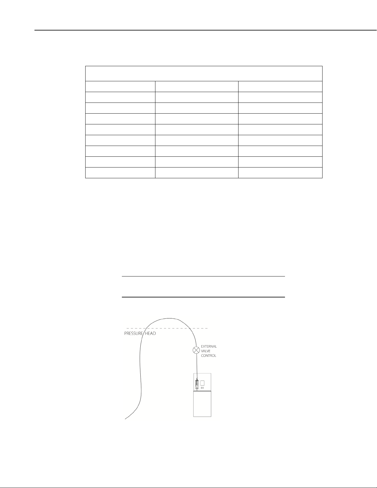
2. Looping the intake tube. For small amounts of pressure, looping the
intake tube up to a height that the water pressure cannot push above is a
simple way of getting around the issue. The maximum height would be
the maximum vertical draw, 3.4 m (27.5 ft).
TABLE 5-5. Sanitary System Changes
NOTE
We recommend using a valve with external valve control in this
kind of situation, to be on the same side. See FIGURE 5-8.
FIGURE 5-8. Vertical loop for pressurized source
18
Page 27
CVS4200 / BVS4300 Stationary Samplers
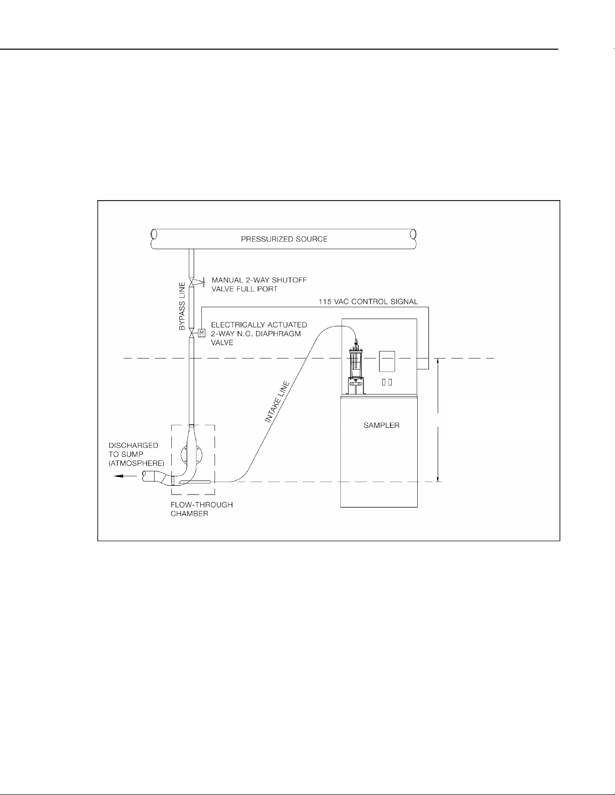
3. Flow-Through Chamber. Divert liquid from the pressurized line to a
“wet well” or secondary pool, and attach this component to it, as shown in
FIGURE 5-9.
4. Configuring a Combination of Valves. Using a combination of valves,
such as pressure reducing valves and ball valves, previous customers have
successfully managed to take samples under a certain amount of pressure
without flooding the system.
FLOW-THROUGH CHAMBER
MUST BE INSTALLED BELOW
ELEVATION OF METERING
CHAMBER TO AVOID
FLOODING OF SAMPLER.
FIGURE 5-9. Flow-through chamber for pressurized source
19
Page 28

CVS4200 / BVS4300 Stationary Samplers
6. Specifications
Features:
• Rapid transport velocities of samples (horizontal draws 76.2 m (250
ft) at 0.8 m s
solids.
• All information is easily controlled and viewable on a 2 by 16
character backlit LCD.
• Vacuum technology benefits over peristaltic pump samplers:
o Accurate sample volumes,
o Rapid transport velocities mean more-representative samples,
o Less disturbance of sample,
o Minimal wear on the tubing, resulting in less-frequent
maintenance,
o Reduced cross-sample contamination.
Compatible Dataloggers: CR200(X)-series
CR800 series
CR1000
CR3000
CR5000
CR9000X
CR510
CR10(X)
CR23X
CR7
21X
–1
(2.5 ft s–1), meaning more accurate samples, even of
20
Page 29

CVS4200 / BVS4300 Stationary Samplers
6.1 BVS4300 Outdoor Stationary Sampler Specifications
TABLE 6-1. BVS4300 Sampler Specifications
Dimensions
Weight
Enclosure
Cold-Weather Option
Hot-Weather Option
Power Requirements
Operating
Temperature
Height: 1.6 m (63 in)
Width: 0.66 m (26 in)
Depth: 0.66 m (26 in)
Refrigerated Weight: 141 kg (310 lb)
Non-Refrigerated Weight: 109 kg (240 lb)
NEMA 4 weatherproof 14-gauge steel enclosure
with heat cured polyester-based powder paint for
corrosion resistance, and lockable door with one set
of keys.
Insulation with thermostatically controlled forced-air
heater.
Cabinet circulation fan(s) prolong life expectancy of
refrigerator in hot settings.
Sampler:
DC Output: 13.6 V, 10 A.
AC Input: 88 to 264 Vac, 50/60 Hz, 2.5 A (max 3 A)
Refrigerator: 115 Vac, 60 Hz
Small Fridge: 1.3 A
Large Fridge: 2 A
Heater: 115 Vac, 60 Hz. 3.5 A
Standard: 0º to 50ºC (32º to 122ºF)
With Optional Heater & Insulation: –40º to +50ºC
(–40ºF to +122ºF)
Storage Temperature
–30º to +60ºC (–22º to +140ºF)
21
Page 30

CVS4200 / BVS4300 Stationary Samplers
6.2 CVS4200 Indoor Stationary Sampler Specifications
TABLE 6-2. CVS4200 Sampler Specifications
Dimensions
Weight
Enclosure
Power Requirements
Refrigerated Composite:
Height: 1.40 m (55 in)
Width: 0.53 m (21 in)
Depth: 0.56 m (22 in)
Refrigerated Discrete:
Height: 1.45 m (57 in)
Width: 0.61 m (24 in)
Depth: 0.61 m (24 in)
Non-Refrigerated:
Height: 0.59 m (23 in)
Width: 0.43 m (17 in)
Depth: 0.48 m (18.75 in)
Refrigerated Composite: 68 kg (150 lb)
Refrigerated Discrete: 91 kg (200 lb)
Non-Refrigerated: 32 kg (70 lb)
NEMA 1 general purpose, 14 gauge steel enclosure
(upper control section only) with polyester-based
powder paint for corrosion resistance.
Sampler:
DC Output: 13.6 V, 10 A.
AC Input: 88 to 264 Vac, 50/60 Hz, 2.5 A (max 3 A)
Refrigerator: 115 Vac, 60 Hz
Small Fridge: 1.3 A
Large Fridge: 2 A
Operating
Temperature
Storage Temperature
10º to 50ºC (50º to 122ºF)
–30º to +60ºC (–22º to +140ºF)
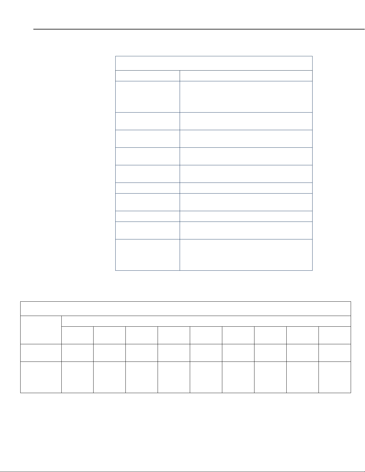
6.3 Controller Specifications
TABLE 6-3. Controller Specifications
Feature Function Capability
START DELAY
Time/Day Adjustable, up to 1 week in advance.
Pulse Count Adjustable, up to 9,999,999.
4-20mA Adjustable, up to 9,999,999 (4 to 20 mA = 0 to 100 pulses/min).
External Contact Momentary, 25 millisecond dry contact closure.
Level Control Adjustable up to 99 second contact duration.
Disabled No start delay.
22
Page 31

CVS4200 / BVS4300 Stationary Samplers
TABLE 6-4. Controller Specifications
SAMPLE
Disabled No sample initiation.
INITIATION
Interval Time Adjustable up to 999 hours, 99 minutes.
Pulse Count Adjustable, up to 9,999,999.
4-20mA Adjustable, up to 9,999,999 (4 to 20 mA = 0 to 100 pulses/min).
External Contact Momentary, 25 ms dry contact closure.
PROGRAM TYPE
CLOCK
PINCH VALVE
PURGE CYCLE
SUCTION CYCLE
Composite Terminate after up to 9,999,999 samples.
Multi-Composite Adjustable, up to 99 cycles per bottle.
Consecutive Adjustable, up to 9 bottles per cycle.
Daily Cycle Adjustable, up to 9 bottles per day.
Timed Step Adjustable, up to 99 hours, 99 minutes per step.
Real Time Clock Real time operating system.
Sample release Adjustable, normally open / normally closed.
Draw and purge time Adjustable, 1 to 99 seconds.
Variable
Adjusts automatically to double the value of the purge time
setting or until liquid contacts level electrode in metering
chamber.
Vacuum
System pressure range is –14 to +20 psi, which can be shown
on the Optional Pressure Gauge.
ALARM OUTPUTS
STATUS OUTPUTS
DIRECT
FUNCTION KEYS
Independent Container Full (Latched. Any key resets. NPN*)
Sample Fault (Latched. Any key resets. NPN*)
Cycle Abandoned (Pulsed. NPN*)
*NPN (sinking) – see Technical Appendix for details.
Independent Sample Taken (DC relay driver, sinking)
Manual Sample
Samples manually when pressed twice. Does not interrupt
program.
Manual Purge Purges system during second press as long as button is pressed.
Manual Bottle
Moves distributor arm to next bottle.
Advance
AVAILABLE
Restart Re-initiates program when pressed twice.
Real-Time Clock
DISPLAYS
Process Timing Elapsed, remaining.
Process Totals
Pulse Counting Internal/external.
Event Response With time stamp.
Multi-Level
Descriptions
Flashing Text
AUTOMATIC
Container Full Sample program complete.
DISPLAYS
Fault Program not completed.
Power Interrupt –
Program Resumed
Alternating Time
Stamp
Cycle(s) Abandoned
23
Page 32
CVS4200 / BVS4300 Stationary Samplers
6.4 Vacuum System Specifications
Feature Description
TABLE 6-5. Vacuum System Specifications
Switches
Sample Volume
Maximum Horizontal
Transport Distance
Maximum Vertical
Lift
Metering Chamber
Cover
Volume Control Tube
Metering Chamber
Level Electrode
Intake Hose Material
Discharge Hose
Material
Refrigerator
Run/Off (SPST Toggle).
Power On/Off (5 A lighted breaker).
Refrigerator On/Off (5 A lighted breaker).
Heater On/Off (5 A lighted breaker).
Adjustable, 50 to 500 cc
Adjustable, 50 to 1,000 cc
76.2 m (250 ft); assumes no vertical lift
8.2 m (27 ft) for 3/8 inch system
6.1 m (20 ft) for 5/8 inch system
Nylon
316 stainless steel
316 stainless steel
Nylon-Reinforced PVC
Latex
Small (composite): 4.4 cu ft, adjustable to 4ºC.
(optional)
Large (discrete): 5.8 cu ft, adjustable to 4ºC, glassdoor, digital display. (optional)
System Size
3/8 inch
5/8 inch
(composite
samplers
only)
24
6.5 Sample Transport Velocity
TABLE 6-6. Vertical Velocity
0 m
(0 ft)
2.16 m s
(7.1 ft s
1.52 m s
-1
(5 ft s
)
-1
-1
-1
)
1.5 m
(5 ft)
2.16 m s
(7.1 ft s
1.40 m s
(4.6 ft s
-1
-1
-1
)
-1
)
3.1 m
(10 ft)
1.83 m s
-1
(6 ft s
1.19 m s
(3.9 ft s
)
-1
-1
-1
)
4.6 m
(15 ft)
1.52 m s
-1
(5 ft s
0.94 m s
(3.1 ft s
)
-1
-1
-1
)
Height
5.5 m
(18 ft)
1.34 m s
(4.4 ft s
0.82 m s
(2.7 ft s
-1
-1
-1
)
-1
)
6.1 m
(20 ft)
1.25 m s
(4.1 ft s
0.55 m s
(1.8 ft s
-1
-1
-1
)
-1
)
6.7 m
(22 ft)
1.10 m s
(3.6 ft s
-1
0 m s
-1
(0 ft s
7.6 m
(25 ft)
-1
0.91 m s
-1
)
(3 ft s
)
-1
-1
)
8.2 m
(27 ft)
0.79 m s
(2.6 ft s
-1
-1
)
Page 33

System Size
3/8 inch
7.6 m
(25 ft)
2.16 m s
(7.1 ft s
CVS4200 / BVS4300 Stationary Samplers
TABLE 6-7. Horizontal Lift
Distance
15.2 m
(50 ft)
-1
1.89 m s
-1
)
(6.2 ft s
22.9 m
(75 ft)
-1
1.71 m s
-1
)
(5.6 ft s
30.5 m
(100 ft)
-1
1.52 m s
-1
)
(5 ft s
-1
53.3 m
(175 ft)
-1
1.22 m s
)
(4 ft s
-1
61 m
(200 ft)
-1
1.13 m s
)
(3.7 ft s
76.2 m
(250 ft)
-1
0.79 m s
-1
)
(2.6 ft s
-1
-1
)
5/8 inch
(composite
samplers only)
1.52 m s
-1
(5 ft s
-1
1.43 m s
)
(4.7 ft s
-1
1.31 m s
-1
)
(4.3 ft s
-1
1.28 m s
-1
)
(4.2 ft s
-1
1.13 m s
-1
)
(3.7 ft s
-1
-1
)
1.01 m s
(3.3 ft s
-1
0.73 m s
-1
)
(2.4 ft s
-1
-1
)
25
Page 34

CVS4200 / BVS4300 Stationary Samplers
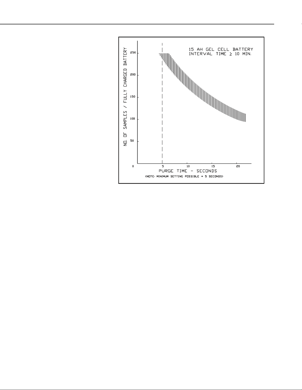
6.5.1 Using Velocity to Calculate Purge Time
Purge time of the sampler needs to be programmed based on the length of hose
and the velocity at which the liquid will travel through the hose. The formula
is l / v = p (length / velocity = min. purge time).
NOTE
6.5.2 Horizontal/Vertical Combinations
7. Operation
7.1 Use in Adverse Conditions
Adding a few seconds to the purge time is recommended to
ensure the line is fully cleared of any obstructions.
Example: 100 ft of hose, at 5 ft s–1, requires a minimum 20 s purge time. 100 /
5 = 20 s. The number input for purge time should be a minimum of 20, but
preferably 24.
Standard purge time for 25 ft of intake tube is 10 s. Although a standard 25 ft
hose will sample in less than 4 seconds, 10 s is the minimum recommended for
proper clearing of the line.
The velocity charts above measure only horizontal or only vertical. Most
applications will have combinations of both. With 61 m (200 ft) of intake
tubing, CVS/BVS Samplers are capable of drawing a sample above 0.6 m s
–1
) at 6.1 m (20 ft) of vertical. At 7 m (23 ft) of vertical with 61 m (200
(2 ft s
ft) of intake tubing, sampling may or may not be successful, depending on
altitude and other factors. For more detailed information for your specific
application, please contact a Campbell Scientific applications engineer.
–1
7.1.1 Exhaust
When the sampling sequence is in the suction cycle, the air removed from the
metering chamber and intake hose is vented externally through the exhaust
fitting. If the unit is installed indoors and detrimental air conditions exist in the
sample lines, the exhaust should be vented outdoors. To vent the exhaust,
connect a hose to the pump exhaust connection (13 on FIGURE 5-1) and route
the hose outdoors.
7.1.2 Instrument Air
Under adverse atmospheric conditions (humid, corrosive, etc.), compressed air
should be used to purge the cabinet and provide clean air for the pump intake.
Connect the tubing for the air tank to the fittings located on the left side of the
BVS enclosure (14 on FIGURE 5-1).
WARNING
Failure to purge the cabinet in harsh conditions may
cause damage to the sampler and loss of warranty.
26
Page 35

7.1.3 Freezing Conditions
If the sampler is located outdoors in freezing conditions, we recommend a
BVS4300 with a factory installed heater and insulation.
CVS4200 / BVS4300 Stationary Samplers
NOTE
CAUTION
As the interior floor of the cabinets is not insulated, an added
insulating factor is to fill the cavity under the cabinet between
the mounting legs. This can best be accomplished using 5 cm (2
in) foam board (available from your local building supply store).
Intake hose should be positioned to have as little horizontal distance as
possible, so that no water can collect in the line and freeze.
In extreme cold conditions the intake hose should be
insulated and/or heated.
If the hose is positioned mostly vertical, the most prone point of freezing is
where the hose enters the frozen water source.
7.2 Power Line/Wiring Considerations
CAUTION
A noise free or clean line from primary power is highly
recommended to supply the CVS/BVS sampler. Never run
wiring in the same conduit as the aforementioned or
together with any telephone line(s).
Bring power from main distribution panel along a path that does not parallel
any existing power wiring to motors, solenoids, or contactors.
CAUTION
When sampler power line must cross existing power lines, do so at right
angles.
Wiring to remote/external functions should avoid all AC
power lines if possible and/or run in shielded cable
terminating the shield at the AC ground terminal on the
sampler main terminal block, or at the remote site, but not
both.
27
Page 36

CVS4200 / BVS4300 Stationary Samplers
7.3 Operating Sequence
7.3.1 Sampling Sequence
SAMPLING PROCESS:
1. High pressure air purge of intake hose.
2. Liquid is drawn into the metering chamber, up to the liquid sensing rod.
3. All excess liquid is purged from the system down to the level set by the
volume control tube.
4. The sample is then released into either one composite container or one of
several discrete containers.
The sampling sequence begins with a high pressure air purge of the intake
assembly to remove residual liquid and obstructions. Upon completion of the
pre-purge cycle, the system converts to a vacuum state, drawing the sample
through the intake hose into the metering chamber. The system then
pressurizes, ejecting excess fluid back through the intake line until the
predetermined sample volume is achieved. The sample is then deposited under
pressure into the sample container while the post purge again clears the intake
line of any residual liquid.
Should the sampler, for any reason, not be able to draw a sufficient volume of
fluid to obtain a sample, the unit automatically initiates a second attempt.
Should a sample still not be delivered, the sequence will be abandoned and the
unit will await the next initiation. Upon two consecutive failures, the sampler
will suspend the sampling program until manually RESTARTed.
28
Page 37

If programmed with the FAULT SHUTDOWN “disabled”, the sampler will
not make a second attempt to draw the sample, but will simply abandon it and
await the next sample initiation. Neither will the unit suspend the sampling
program after consecutive failures. This function is provided for use in the
event that the sample source may be lacking sufficient fluid from which to
draw, for a period of time , yet allows the sampler to continue operating
without a FAULT SHUTDOWN occurring. The second attempt is not made to
prevent unnecessary wear on the sampler.
7.3.2 Line Voltage Failure
Should the sampler have a factory installed internal battery or have an external
battery connected, the sampler will continue operating (with the exception of
the refrigerator and heater). The duration of operation will depend on the
capability and charge level of either battery. The frequency and the length of
each sample cycle will also have an impact on how long the batteries will last.
7.4 Operating Instructions
7.4.1 Sample Volume Adjustments
CVS4200 / BVS4300 Stationary Samplers
CAUTION
Setting the desired sample volume is accomplished by adjusting the height of
the volume control tube within the metering chamber. The tube is mounted
through the top of the chamber with a gland nut fixing the position. To adjust
the sample volume, loosen the nut until the volume control tube may be moved
freely. Raise or lower the bottom end of the tube to the desired volume using
the lines provided on the side of the chamber as a guide (lines are spaced at 100
cc intervals with the exception of one at 50 cc). Tighten the gland nut to hold
the volume control tube at the desired position.
The volume control tube should always be located below
the liquid sensing rod.
29
Page 38

CVS4200 / BVS4300 Stationary Samplers
CAUTION
Hold the bottom nut while loosening / tightening the top
nut, or it may become loosened from the metering
chamber cover and create an imperceptible leak in the
vacuum system.
7.4.2 Liquid Sensing Rod
This probe, also called the “level control rod”, is used to stop the sample
intake. Always ensure that its lower end is located above the volume control
tube. Approximately 1” difference is sufficient. If the fluid intake is turbulent
within the metering chamber, more than 1” may be required to ensure
splashing of fluid does not trigger probe.
In applications with substantial oil or grease, the rods can become coated and
lose their conductivity. This is prevented by cleaning the rods regularly. In
extreme cases, extra SS wire can be wrapped around the liquid sensing rod to
increase its surface area.
CAUTION
The liquid sensing rod and volume control tubes must be
kept clean to ensure conductivity necessary to detect the
presence of the fluid.
Most CVS/BVS Samplers incorporate a Barrier Valve in the metering
chamber cover, where the tubing from the pump enters. It consists of a cage
containing a ball that will float if the sample should rise to the top of the
chamber without detection. Should rod conductivity fail, the fluid brings the
float into contact with an O-ring surrounding the pressure / vacuum port,
sealing the entry to the tubing and the pump (where the fluid may cause serious
damage). This O-ring Barrier Valve should be inspected regularly and
replaced as necessary.
30
Due to the restriction of Wetted Materials (such as, stainless steel, glass and
fluorocarbons, etc.), some models of the sampler do not contain this barrier
valve. In these units, a secondary liquid-sensing circuit may be added as a
precaution. This circuit is connected to the pump tubing fitting on the
Metering Chamber cover.
7.5 Battery
7.5.1 Charging 12 Vdc Battery and Reverse Polarity Protection
The sampler will charge only the factory installed internal battery. This
charging takes place continually as long as there is incoming line power.
Should the need arise to only charge the internal battery, as would be required
to store the sampler for an extended period of time, simply place the “RUN /
OFF” toggle switch in the OFF position, and leave the sampler power breaker
on. Twenty-four (24) hours should be sufficient to fully charge the battery.
The sampler is equipped with REVERSE POLARITY PROTECTION for
checking the connection of an external battery. When attaching an external
battery, be sure to check the reverse polarity indicator. If it is ON, reverse the
connections at the battery.
Page 39
CVS4200 / BVS4300 Stationary Samplers
FIGURE 7-1. Battery performance curve
7.5.2 Sampler Controller Backup Battery
The controller contains a 3.6 V lithium backup battery to maintain user settings
during loss of system power. If power is removed for any reason, the
controller will start a planned shutdown procedure which will save all user
settings while its operating voltage is reduced from 5 V to approximately
3.3 V. The rate at which this voltage drops is slowed by the presence of a
supercapacitor. By the time the voltage has reached 3.3 V, the controller has
safely stored all user settings and entered a “sleep” mode. This is an extremely
low-power mode which is maintained by a trickle of current from the lithium
battery, and can be maintained for many years under normal circumstances.
The battery is located on the top left hand side of the controller. It is accessible
by the removal of the clear cover, and should be changed under powered
conditions. Since the controller is a low-power device, this uncovering can be
safely done, taking care that no conductive implement contacts sensitive circuit
components.
If the controller starts to exhibit certain operating anomalies such as loss of
user settings after sustained power outages or an inability to wake up after a
normal shutdown, it may be due to a low or totally discharged backup battery.
To predict the probability of these events, regular examination of the battery
condition is encouraged. The battery status is easily determined while the
controller is active. The process will not affect a running program. Battery
status can be checked by use of the following Touchpad sequence:
31
Page 40

CVS4200 / BVS4300 Stationary Samplers
1. VIEW, OTHER OPTIONS
2. Select MAINTENANCE, ENTER
3. Select B/U BATTERY TEST, ENTER
The display will then show “PASSED”, “LOW” or “FAULT”. The latter two
require battery replacement (see Section 9.4, Controller Battery Replacement
Procedure).
7.6 Programming
7.6.1 Guidelines
Controller settings may be changed at any time. Changes are termed NEW
ENTRIES. No NEW ENTRIES will be acted upon unless the controller is
RESTARTed. Once RESTARTed, all NEW ENTRIES become ACTIVE
SETTINGS.
Every time the controller is RESTARTed, all accumulators (i.e., SAMPLES
TAKEN, TIME REMAINING, REMAINING PULSES, etc.) are cleared
and the ACTIVE SETTINGS are reloaded unless NEW ENTRIES have been
made.
Remember - Start Delay is reloaded too !!
7.6.1.1 Flashing Text
Flashing text is the system wide prompt that indicates an input is required from
the user. Flashing words or duel flashing digits prompt for arrow keys to be
pressed to scroll through available options. A single flashing digit prompts for
a numeric key to be pressed. When the desired option or number is shown on
the display, press the ENTER key.
7.6.1.2 Real Time Clock
The controller has two basic timing modes. The simplest of these requires no
maintenance; it simply provides a “heartbeat” for various timed functions. The
other timing mode is the REAL TIME CLOCK that is used in several
functions and must be correctly set. This is likely the first item requiring
programming. Although time may have been set at the factory, time zone
shifts may require adjustment of the Real Time Clock.
7.6.1.3 Total Bottles
Since the number of bottles is usually determined by customer requirement at
the time of purchase, this variable will normally be set at the factory to match
the actual container hardware. Choices are restricted to a single container (as
in composite) or 2, 3, 4, 6, 8, 12 or 24. These all form instructions to the
stepper motor in how it will behave when the internal command is given to step
to the next container (as each step increment is 15°).
32
Page 41

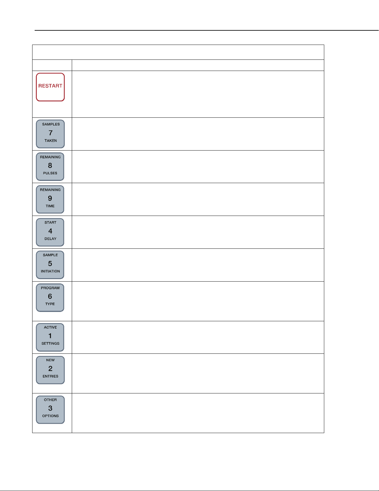
7.6.2 Touchpad Keys
CVS4200 / BVS4300 Stationary Samplers
TABLE 7-1. Touchpad Button Descriptions
Button Description
The VIEW key is used to review alterable parameters currently in use. It has no effect on the
program being executed at the time. Once pressed, the user is prompted for a FUNCTION to be
viewed. The parameters visible under the function can be stepped through using the ENTER key.
The SET key is used to change program settings or the entire sampling program. Changes made
have no effect on the program being executed at the time until the RESTART key is pressed twice.
To leave a programming sequence before entering it in memory, press SET or VIEW and the
sequence is aborted.
The ENTER key is used to complete either a VIEW or SET sequence, where sub-menu items are
available. Under the control of the VIEW key, parameters are scrolled onto the display, changing
with each use of the ENTER key until a complete display of the parameter is completed. Under the
control of the SET key, parameters can be displayed, with the added ability to change their values,
using the ENTER key to accept the new value until the entire parameter is displayed. (Note: New
values are not operational at this time.)
33
Page 42
CVS4200 / BVS4300 Stationary Samplers
TABLE 7-1. Touchpad Button Descriptions
Button Description
The RESTART key is used to load any new parameters into the operating program. Pressing it
twice will initialize the program and terminate any existing sample program. Any parameters
altered under the SET command are updated to the active program. If no parameters have been
changed, the program is reset to its first instruction and the same sampler program is started again.
This key requires a confirming second activation to complete its function. WARNING: Any
program in progress is ended and all data is lost.
SAMPLES TAKEN [VIEW]. The total number of samples taken can be shown on the display.
REMAINING PULSES [VIEW]. In modes using internal or external pulse counting, the current
status of the pulse count can be displayed.
REMAINING TIME [VIEW]. Various views are available dependent on the method used to
gather samples. Program variables will determine whether the displayed time is REMAINING
TIME, ELAPSED TIME or START DELAY.
START DELAY [VIEW/SET]. The start of a sample program can be made to occur at a fixed
time or event. Options: DISABLE, TIME/DAY, PULSE INPUT, 4-20mA INPUT, EXTERNAL
CONTACT, LEVEL CONTROL.
SAMPLE INITIATION [VIEW/SET]. A sample program may be initiated and controlled by
various internal and external parameters. These parameters determine how the program will begin
its actions and how the results will be recorded. Options: DISABLE, INTERVAL TIME, PULSE
INPUT, 4-20mA INPUT, EXTERNAL CONTACT.
PROGRAM TYPE [VIEW/SET]. A sample program can be made to collect samples in a fixed
style so that the results are useable in different ways. The type of program used may be hardware
dependent. This will determine the sampler’s ability to collect and store the desired samples.
Options: COMPOSITE, DAILY CYCLE, CONSECUTIVE, MULTI-COMPOSITE, TIMED
STEP.
34
ACTIVE SETTINGS [VIEW]. Current sample program parameters can be reviewed by scrolling
through them using the ENTER key as a toggle.
NEW ENTRIES [SET]. Program all major program settings at once (including START DELAY,
SAMPLE INITIATION, PROGRAM TYPE, and PURGE TIME).
[VIEW]. Review parameters that have been changed since the sample program was started (only if
the changes have been properly ENTERED). Scroll through them using the ENTER key as a
toggle.
OTHER OPTIONS [VIEW/SET]. Various options relating to equipment and information
retrieval are available under this key. Changes in equipment setup can be entered here, and certain
status information is also available here. Options: CLOCK, PURGE TIME, PINCH VALVE,
FAULT SHUTDOWN, SAMPLER STATUS, CYCLES ABANDONED, BOTTLE POSITION,
MAINTENANCE.
Page 43

TABLE 7-1. Touchpad Button Descriptions
Button Description
MANUAL PURGE. Purges the intake line independent of program control, as long as a
programmed cycle has not started. Sampler starts its pump, creating pressure in the sample intake
tube to purge it of any excess material that may be present. Button must be pressed twice to purge
line. Sustained pressure on the key during the second press will cause purging to continue until the
key is released.
MANUAL ADVANCE. Distributor arm advances one position (for example, to next bottle),
dependent on the equipment available (discrete samplers only). This action is NOT updated to
any current sampler program. Button must be pressed twice to initiate manual advance.
MANUAL SAMPLE. Initiate a single Sample Cycle. Sampler must not be engaged in a sampling
event at the time. This action and any resulting sample collected are NOT updated to any
current sampler program. The Bottle Position is NOT advanced. Program will continue
uninterrupted. Button must be pressed twice to initiate manual sample. Whether successful or
not, the display will read “MANUAL SAMPLE Completed”.
7.6.3 General Terms
CVS4200 / BVS4300 Stationary Samplers
Many of the functions available on the Touchpad have a variety of options to
enhance their capabilities. These options are programmable from the
Touchpad and require only that the sampler have the correct equipment
configuration to utilize them.
DISABLE
The display showing disabled will reflect the status of any function not being
used.
TIME/DAY
The basis for several timed functions is the Real Time Operating System.
Time (of) Day will be a means of setting the timing period for the START
DELAY function. The format is on a weekly basis, requiring hour, minute,
AM/PM and day inputs (HH:MM AM SUN). This means the START
DELAY can be set to any particular minute in a week.
INTERVAL TIME
Sampler operation can be controlled by fixed time intervals which do not
require Time/Day setting. SAMPLE INITIATION has an option whereby an
interval time can be set between sample cycles. The controller will cause
samples to be taken on a timed interval basis, continuing until the sample
program is completed by a full jar or operator intercession.
PULSE INPUT
This option will allow the controller to determine the sampler operation based
on external criteria. Pulses fed to an internal accumulator in the controller will
be compared to the setting entered by the operator and will cause a sample
cycle to start. The accumulator will reset immediately and counting of pulses
35
Page 44

CVS4200 / BVS4300 Stationary Samplers
will begin again. There is no loss of count the sample cycle. Pulse
requirements of the system are detailed in the specifications.
4-20mA INPUT
Where external devices do not themselves generate pulses in any relation to
their process but generate a current signal of 4-20mA, this input option will
generate internal pulses proportional to the incoming 4-20mA signal. These
can then be treated the same as the Pulse Input option and accumulated in the
controller to determine when a sample cycle will occur.
EXTERNAL CONTACT
The sampler controller can react to an external, dry contact, otherwise known
as a zero-voltage contact, to activate a sample cycle on demand. This will
generally be when external conditions have caused a relay to close, requiring a
sample be taken at that time.
LEVEL CONTROL
The START DELAY function is a special case of the external contact option
where the contact signal is required to be present for a pre-programmed time.
This enables verification of the signal where fluctuations may occur in the level
which would trigger samples at unwanted times. This is the only case in which
the START DELAY is not a single timed event. The operation of the sampler
after the level signal is verified will be controlled by whatever function is set in
the SAMPLE INITIATION. It will continue until the level drops or the
function is terminated by the controller. If the level drops before the function
is finished, any sample cycle already in progress will be completed and then
the system will shut down until the next verified level control signal.
COMPOSITE
A program option which determines that all the samples that are gathered will
be placed in a single container. The sample program terminates after a specific
number of samples.
MULTI-COMPOSITE
This option is used for discrete sampling applications, to deposit multiple
samples to one container before advancing the distributor mechanism to the
next container. The interval between each sample is controlled by the
SAMPLE INITIATION options. The multi-composite setting is
programmable up to 99 samples per container, for up to 24 containers
depending on the hardware configuration.
CONSECUTIVE
This option is used for discrete sampling applications, to successively deposit
one sample to each of a programmed number of containers on any given
sample initiation. The consecutive setting is programmable up to 99 containers
per sample initiation, although this may be severely limited by hardware
configuration.
36
Page 45
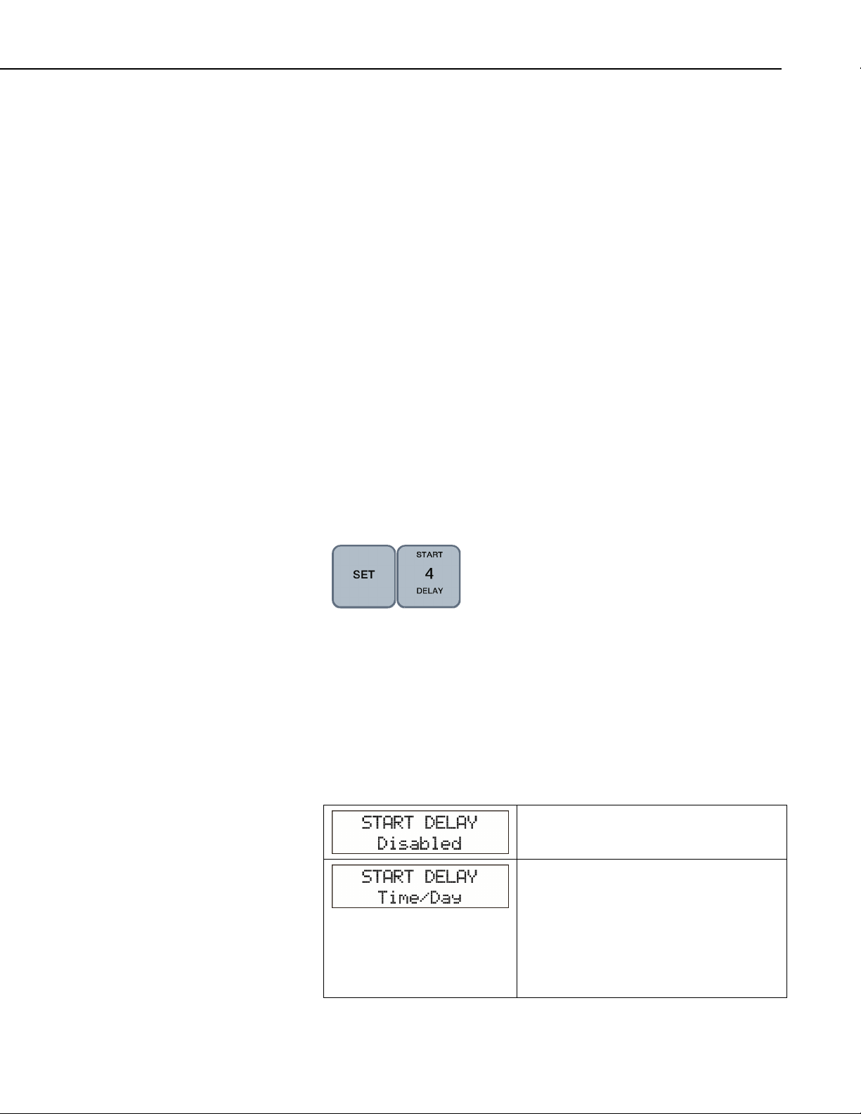
CVS4200 / BVS4300 Stationary Samplers
DAILY CYCLE
Allows the sampler to deposit equal sample volumes into a predetermined
number of containers per programmed day. Each day may have any number of
samples taken, dependent on the SAMPLE INITIATION mode chosen.
Deposits are made to as many as 9 containers per day, to a cumulative total of
24 containers. (For example, choosing a 24 bottle format, the sampler may be
programmed to deposit to Three (3) bottles on any six days of the week,
together with up to Six (6) bottles on the seventh.) Timing is dependent on the
crystal-controlled Real Time Clock in the controller. The first program day
will be the current day the programming is done, unless the START DELAY
option is chosen to determine when sampling will begin.
TIMED STEP (Override)
This option will cause the sample distributor to step to a new container
regardless of the status of the SAMPLE INITIATION setting. For example,
the actual sampling may be under the control of a flowmeter and taking
samples based on the flow rate as determined by pulses or 4-20mA input to the
controller. When the user-programmed Timed interval has elapsed, the
controller will Step to a new container. The Timed Step can be set for any
interval up to 99 hours 59 minutes. Progress of the step timer can be viewed
by selecting View, Program Type and pressing ENTER twice. Thus you may
view the REMAINING TIME or the step timing.
7.6.4 Programming START DELAY
7.6.4.1 START DELAY Overview
START DELAY is the function which will delay the beginning of a sample
program until certain external conditions are met. Upon meeting those
conditions, the sampler will initiate a sample cycle and then operate based on
the SAMPLE INITIATION parameters. Under START DELAY, flashing
text prompts the user to scroll through available options by pressing arrow
keys. These options only require that the correct equipment is present to utilize
them. The last option selected in previous programming will be the first to
appear on the display.
The display showing Disabled will reflect
the fact that the function is not being used.
The basis for several timed functions is the
Real Time Operating System. Time (of) Day
will be a means of setting the timing period
for the START DELAY function. The
format is on a weekly basis, requiring hour,
minute, AM/PM and day inputs (HH:MM
AM SUN). This means the start of a sampler
program can be delayed up to seven days.
37
Page 46
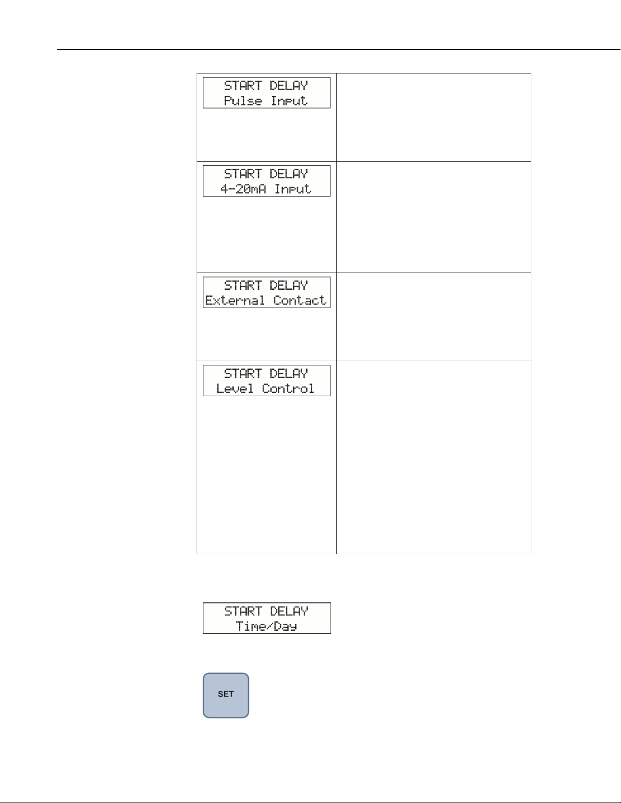
CVS4200 / BVS4300 Stationary Samplers
This option will allow the controller to
determine the sampler’s start of operation
based on external pulses. Pulses fed to an
internal accumulator in the controller will be
compared to the setting entered by the
operator. Pulse requirements of the system
are detailed in the specifications.
Where external devices do not themselves
generate pulses in any relation to their
process but generate a current signal of 420mA, this input option will generate
internal pulses proportional to the incoming
4-20mA signal. These can then be treated
the same as the Pulse Input option a
nd
accumulated in the controller to determine
when a sample program should start.
The sampler controller can react to an
external dry contact, otherwise known as a
zero-voltage contact, to activate a sample
program on demand. This will generally be
when external conditions have caused a
relay to close, requiring a sample program
be started at that tim e.
7.6.4.2 START DELAY using Time/Day
This option is a special case of the external
contact option. The key difference is that
the contact closure must be present fo
pre-programmed time, thus enabling
verification of the signal. This will
accommodate fluctuations as seen in a level
switch, thereby avoiding triggering of
samples at unwanted times. This is the only
case in which the START DELAY is not a
single timed event. Should the contact open
for the same pre-programmed time, the
sampler will, after completing any sample
cycle already in progress, halt the sampling
initiation and await the next verified signal.
At this time, the sampling program will
resume.
The following sequence of entries are made
on the Touchpad to create a future starting
time for the operation of the Sampler. The
ACTIVE SETTINGS are not being altered.
r a
38
1. Press the SET key.
Page 47
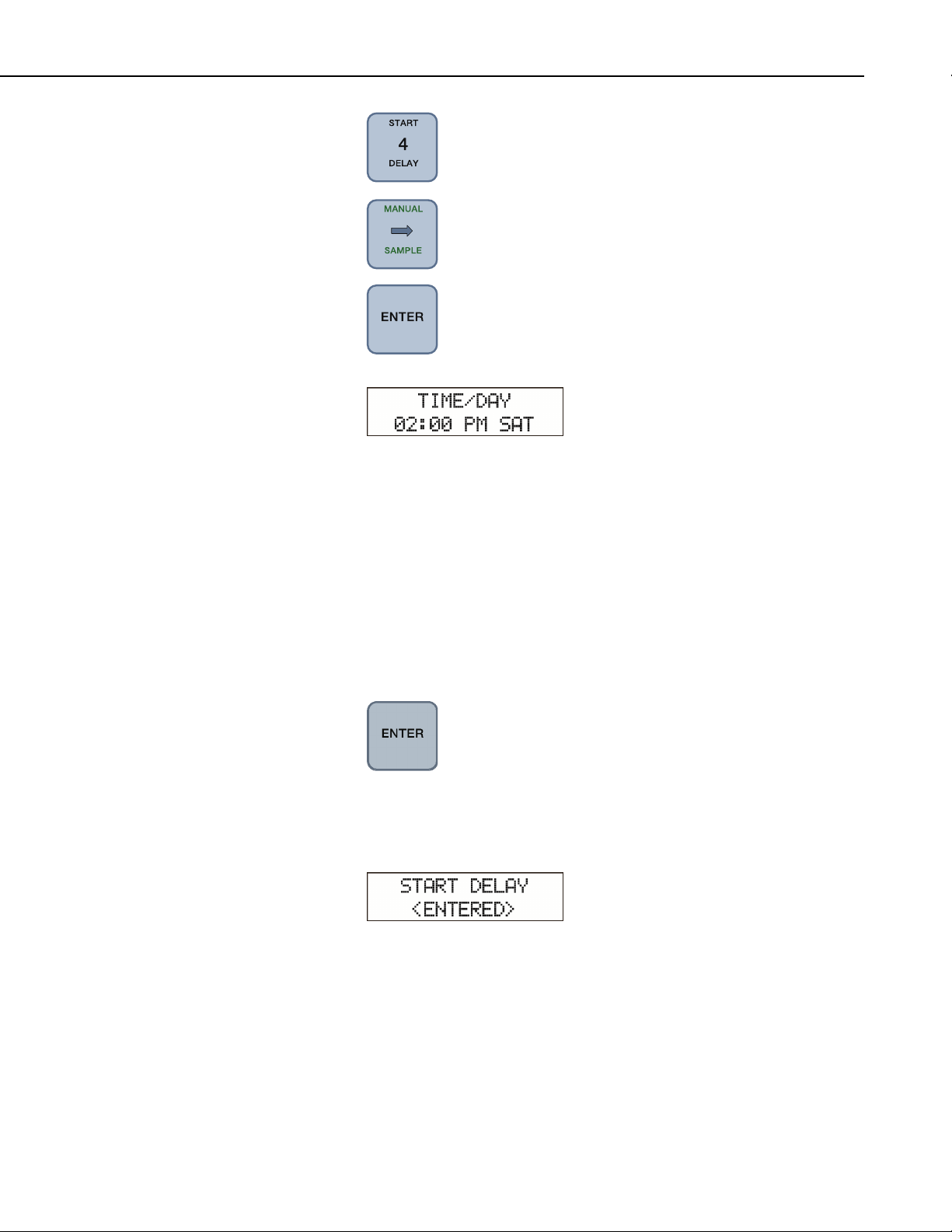
CVS4200 / BVS4300 Stationary Samplers
2. Press the START DELAY key.
3. Press an ARROW key. Continue until
Time/Day is shown on the display.
4. Press the ENTER key.
When setting the time, a single flashing digit
indicates an input from a numeric key is
required. Press a number key to enter a
value. The next digits flash in succession.
Enter each as required. The format is
HH:MM.
When the four digits are entered, press
ENTER. Any wrong entries will require reentry. There are two methods of correcting a
mistake. The digit flashing “wraps around”
and begins again, at which time the correct
entry may be pressed. Alternately, the arrow
keys can be used to reposition the flashing
prompt over the error, which can then be
replaced with the correct value.
The flashing prompt advances to the
AM/PM indicator. Press the ARROW key
until the right indicator is shown. Press
ENTER.
The flashing prompt advances to the day
indicator. Press the ARROW key repeatedly
until the correct day appears. Press ENTER.
The display will echo the last entry with
<ENTERED>.
39
Page 48
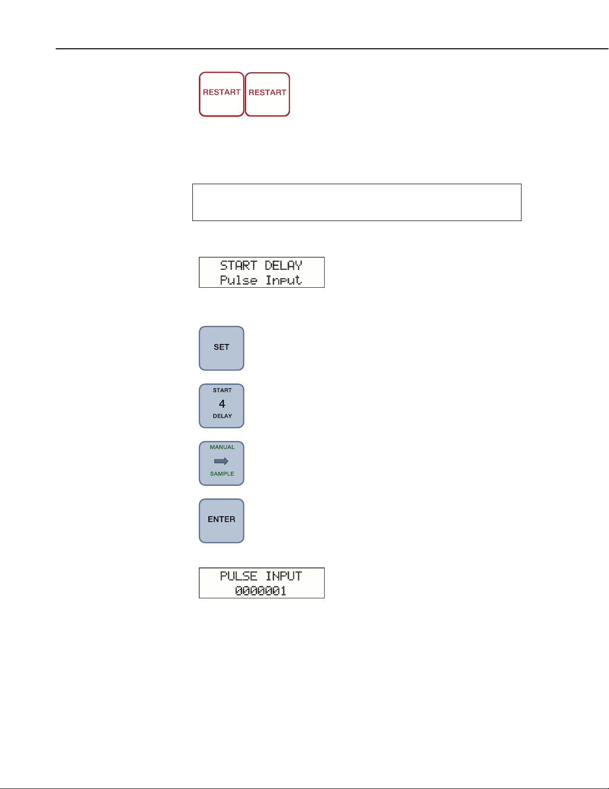
CVS4200 / BVS4300 Stationary Samplers
Summary of Sequence:
SET, START DELAY, ARROW(S), ENTER, #, #, #, #, ENTER,
ARROW(S), ENTER, ARROW(S), ENTER, RESTART, RESTART.
7.6.4.3 START DELAY using Pulse Input
The controller has now been given a new
value for START DELAY. The new values
reside in the NEW ENTRIES area of the
controller memory. To make these changes
active, press the RESTART key; press it
again to confirm your choice. The controller
will then wait until the designated time
before starting its sampling program.
The following sequence of entries are made
on the Touchpad to create a future starting
time for the operation of the Sampler. The
ACTIVE SETTINGS are not being altered.
1. Press the SET key.
2. Press the START DELAY key.
3. Press an ARROW key. Continue until
Pulse Input is shown on the display.
4. Press the ENTER key.
The display will show a new screen
containing the option title PULSE INPUT
on the top line and a 7 digit number with the
leftmost digit flashing as an input prompt.
To set the number of pulses required to be
input before a sample program is started, use
the ARROW keys to move the flashing
prompt until it is over the digit requiring
change.
40
Page 49

CVS4200 / BVS4300 Stationary Samplers
Press a number key (0-9) to replace any
existing number and advance the flashing
prompt to the next digit to change. Replace
digits as required, then press ENTER.
The display will echo the last entry with
<ENTERED>.
Any wrong entries will require re-entry. If
ENTER has not been pressed, reposition the
prompt over the incorrect digit and replace
it. After ENTER has been pressed, the entire
entry must be redone from the beginning
(press SET).
The controller has now been given a new
value for START DELAY. The new values
reside in the NEW ENTRIES area of the
controller memory. To make these changes
active, press the RESTART key; press it
again to confirm your choice. The controller
will then wait until the required pulses have
been received before starting its sampling
program.
Summary of Sequence:
SET, START DELAY, ARROW(S), ENTER, #######, ENTER,
RESTART, RESTART.
7.6.4.4 START DELAY using 4-20mA Input
The following sequence of entries are made
on the Touchpad to create a future starting
time for the operation of the Sampler. The
ACTIVE SETTINGS are not being altered.
1. Press the SET key.
2. Press the START DELAY key.
3. Press an ARROW key. Continue until 4-
20mA Input is shown on the display.
41
Page 50
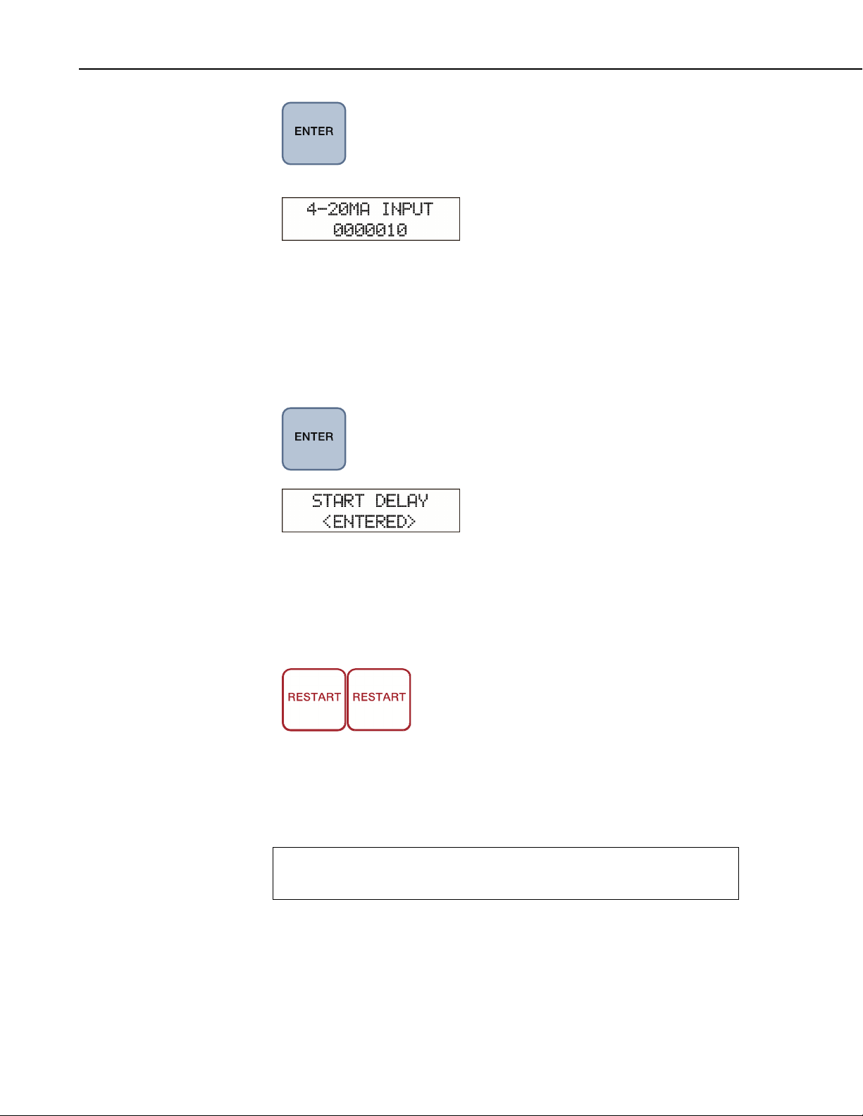
CVS4200 / BVS4300 Stationary Samplers
4. Press the ENTER key.
The display will show a new screen
containing the option title 4-20mA INPUT
on the top line and a 7 digit number with the
leftmost digit flashing as a prompt for input.
The 4-20mA input will be converted by the
controller to pulses, proportional to the span
of the input, at the rate set in the
specifications. To set the number of pulses
required to be input before a sample program
is started, use the ARROW keys to move
the flashing prompt until it is over the digit
requiring change.
Press a number key (0-9) to replace any
existing number and advance the flashing
prompt to the next digit to change. Replace
digits as required, then press ENTER.
The display will echo the last entry with
<ENTERED>.
Any wrong entries will require re-entry. If
ENTER has not been pressed, reposition the
flashing prompt over the incorrect digit and
replace it. After ENTER has been pressed,
the entire entry must be redone from the
beginning (press SET).
The controller has now been given a new
value for START DELAY. The new values
reside in the NEW ENTRIES area of the
controller memory. To make these changes
active, press the RESTART key; press it
again to confirm your choice. The controller
will then wait until the required pulses have
been received before starting its sampling
program
Summary of Sequence:
SET, START DELAY, ARROW(S), ENTER, #######, ENTER,
RESTART, RESTART.
42
Page 51

7.6.4.5 START DELAY using External Contact
CVS4200 / BVS4300 Stationary Samplers
The following sequence of entries are made
on the Touchpad to create a future starting
time for the operation of the Sampler. The
ACTIVE SETTINGS are not being altered.
1. Press the SET key.
2. Press the START DELAY key.
3. Press an ARROW key. Continue until
External Contact is shown on the display.
4. Press the ENTER key.
The display will echo the last entry with
<ENTERED>.
The controller has now been given a new
value for START DELAY. The new value
resides in the NEW ENTRIES area of the
controller memory. To make this change
active, press the RESTART key; press it
again to confirm your choice. The controller
will then wait until it receives a contact
closure (at the External Start inputs on the
terminal block) before starting its sampling
program.
Summary of Sequence:
SET, START DELAY, ARROW(S), ENTER, RESTART, RESTART.
7.6.4.6 START DELAY using Level Control
The following sequence of entries are made
on the Touchpad to create a future starting
time for the operation of the Sampler. The
ACTIVE SETTINGS are not being altered.
43
Page 52

CVS4200 / BVS4300 Stationary Samplers
1. Press the SET key.
2. Press the START DELAY key.
3. Press an ARROW key. Continue until
Level Control is shown on the display.
4. Press the ENTER key.
The display will change to read “Minimum
Contact Time: 03 seconds”. The actual time
shown may be any two digit number. The
first digit will be flashing as a prompt for
input.
Press a number key (0-9). The number will
replace the current number and advance the
flashing prompt to the next digit. Press a
second number key (0-9). Repeat this
procedure if number is wrong, until desired
time is displayed. Press the ENTER key.
The display will echo the last entry with
START DELAY, <ENTERED>.
The controller has now been given a new
value for START DELAY. The new
values reside in the NEW ENTRIES area of
the controller memory. To make these
changes active, press the RESTART key;
press it again to confirm your choice. The
controller will then wait until it receives a
contact closure (at the External Start
inputs on the terminal block). The contact
must remain closed for the length of time
programmed in the steps above.
44
Page 53

Summary of Sequence:
SET, START DELAY, ARROW(S), ENTER, ##, ENTER, RESTART,
RESTART.
7.6.5 Programming SAMPLE INITIATION
7.6.5.1 SAMPLE INITIATION Overview
SAMPLE INITIATION is the function that will determine the frequency that
samples are drawn. A variety of options to enhance the capabilities of this
function are available on the Touchpad. When the SAMPLE INITIATION
has been chosen to be set, a list of options is presented as flashing text below
the main heading of the function selected. The list is advanced using the
ARROW keys (any direction) until the desired option is displayed. These
options are programmable from the Touchpad and require only that the sampler
have the correct equipment configuration to utilize them. The last option
selected in previous programming will be the first to appear on the display.
CVS4200 / BVS4300 Stationary Samplers
The display showing disabled will reflect
the fact that the function is not being used.
Sampler operation can be started at uniform
intervals. This option allows an interval time
to be set between sample cycles.
This option will allow the controller to
determine the SAMPLE INITIATION
based on external pulses. Pulses fed to an
internal accumulator in the controller will be
compared to the setting entered by the
operator and will cause a sample cycle to
start. The accumulator will reset
immediately and counting of pulses will
begin again. There is no loss of count during
the sample cycle.
Where external devices do not themselves
generate pulses in any relation to their
process but generate a current signal of 420mA, this input option will generate
internal pulses proportional to the incoming
4-20mA signal. These can then be treated
the same as the Pulse Input option and
accumulated in the controller to determine
when a sample cycle should occur.
45
Page 54

CVS4200 / BVS4300 Stationary Samplers
7.6.5.2 SAMPLE INITIATION using Interval Time
The sampler controller can react to an
external dry contact, otherwise known as a
zero-voltage contact, to activate a sample
cycle on demand. This will generally be
when external conditions have caused a
relay to close, whose contact will cause a
sample to be taken.
The following sequence of entries are made
on the Touchpad to form a basic operating
parameter for operation of the sampler. This
will determine the time from the start of a
sample cycle to the start of the next sample
cycle. No time is lost during the actual
sample cycle. The ACTIVE SETTINGS are
not being altered.
1. Press the SET key.
2. Press the SAMPLE INITIATION key.
3. Press an ARROW key. Continue until
Interval Time is shown on the display.
4. Press the ENTER key.
When setting the time, a flashing digit
prompts for input from a numeric key. To
set the time, press a numeric key to enter a
value and advance to each digit in
succession. The format is HHH:MM. The
minimum time can be set to 1 minute;
however, practical considerations, such as
equipment duty cycle, maintenance and
service life, suggest times of 3 minutes or
longer.
46
Page 55

CVS4200 / BVS4300 Stationary Samplers
When the five digits are entered, press
ENTER. Any wrong entries will require reentry. there are two methods of correcting a
mistake. The digit flashing “wraps around”
and begins again, at which time the correct
entry may be pressed. Alternately, the
arrow keys can be used to reposition the
flashing prompt over the error, which can
then be replaced with the correct value.
The display will echo the last entry with
<ENTERED>.
The controller has now been given a new
value for SAMPLE INITIATION. The new
values reside in the NEW ENTRIES area of
the controller memory. To make these
changes active, press the RESTART key;
press it again to confirm your choice. The
controller will then wait the designated time
before taking a sample.
Summary of Sequence:
SET, SAMPLE INITIATION, ARROW(S), ENTER, ###:##, ENTER,
RESTART, RESTART.
7.6.5.3 SAMPLE INITIATION using Pulse Input
The following sequence of entries are made
on the Touchpad to form a basic operating
parameter for operation of the sampler. This
will determine the number of pulses from the
start of a sample cycle to the start of the next
sample cycle. The ACTIVE SETTINGS are
not being altered.
1. Press the SET key.
2. Press the SAMPLE INITIATION key.
47
Page 56

CVS4200 / BVS4300 Stationary Samplers
3. Press an ARROW key. Continue until
Pulse Input is shown on the display.
4. Press the ENTER key.
The display will show a new screen
containing the option title PULSE INPUT
on the top line and a 7 digit number with the
leftmost digit flashing to prompt for a
numeric input. To set the number of pulses
required to be input before a sample is taken,
by use of the ARROW keys, move the
flashing prompt until it is over the digit
requiring change.
Press a number key (0-9) to replace any
existing number and advance the flashing
prompt to the next digit to change. Replace
digits as required, then press ENTER.
The display will echo the last entry with
<ENTERED>.
Any wrong entries will require re-entry. If
ENTER has not been pressed, reposition the
prompt over the incorrect digit and replace
it. After ENTER has been pressed, the entire
entry must be redone from the beginning
(press SET).
The controller has now been given a new
value for SAMPLE INITIATION. The new
values reside in the NEW ENTRIES area of
the controller memory. To make these
changes active, press the RESTART key;
press it again to confirm your choice. The
controller will then wait until the required
pulses have been received before taking a
sample.
Summary of Sequence:
SET, SAMPLE INITIATION, ARROW(S), ENTER, #######, ENTER,
RESTART, RESTART.
48
Page 57

7.6.5.4 SAMPLE INITIATION using 4-20mA Input
CVS4200 / BVS4300 Stationary Samplers
The following sequence of entries are made
on the Touchpad to form a basic operating
parameter for operation of the sampler. This
will determine the number of pulses from
the start of a sample cycle to the start of the
next sample cycle. The ACTIVE
SETTINGS are not being altered.
1. Press the SET key.
2. Press the SAMPLE INITIATION key
3. Press an ARROW key. Continue until 4-
20mA Input is shown on the display.
4. Press the ENTER key.
The display will show a new screen
containing the option title 4-20mA INPUT
on the top line and a 7 digit number with the
leftmost digit flashing as a prompt for input.
The 4-20mA input will be converted by the
controller to pulses, proportional to the span
of the input, at the rate set in the
specifications. To set the number of pulses
required to be input before a sample is taken,
use the ARROW keys to move the flashing
prompt until it is over the digit requiring
change.
Press a number key (0-9) to replace any
existing number and advance the flashing
prompt to the next digit to change. Replace
digits as required, then press ENTER.
49
Page 58

CVS4200 / BVS4300 Stationary Samplers
Summary of Sequence:
SET, SAMPLE INITIATION, ARROW(S), ENTER, #######, ENTER,
RESTART, RESTART.
The display will echo the last entry with
<ENTERED>.
Any wrong entries will require re-entry. If
ENTER has not been pressed, reposition the
prompt over the incorrect digit and replace
it. After ENTER has been pressed, the entire
entry must be redone from the beginning
(press SET).
The controller has now been given a new
value for SAMPLE INITIATION. The new
values reside in the NEW ENTRIES area of
the controller memory. To make these
changes active, press the RESTART key;
press it again to confirm your choice. The
controller will then wait until the required
pulses have been received before taking a
sample.
7.6.5.5 SAMPLE INITIATION using External Contact
The following sequence of entries are made
on the Touchpad to form a basic operating
parameter for operation of the sampler. This
will determine the time between samples
being taken. The ACTIVE SETTINGS are
not being altered.
1. Press the SET key.
2. Press the SAMPLE INITIATION key.
3. Press an ARROW key. Continue until
External Contact is shown on the display.
4. Press the ENTER key.
50
Page 59

Summary of Sequence:
SET, SAMPLE INITIATION, ARROW(S), ENTER, RESTART,
RESTART.
7.6.6 Programming PROGRAM TYPE
CVS4200 / BVS4300 Stationary Samplers
The display will echo the last entry with
<ENTERED>.
The controller has now been given a new
value for SAMPLE INITIATION. The new
value resides in the NEW ENTRIES area of
the controller memory. To make this change
active, press the RESTART key; press it
again to confirm your choice. The controller
will then wait until a contact closure has
been received before taking a sample.
7.6.6.1 PROGRAM TYPE Overview
PROGRAM TYPE is the function that determines how the sampler will
perform its program. A variety of options are available. These options are
programmable from the Touchpad and require only that the sampler have the
correct equipment configuration to utilize them. The basic function of the
PROGRAM TYPE is to determine the movement of the distributor.
The program option which determines that
all the samples that are gathered will be
placed in a single container. The sampler
program terminates after the specified
number of samples have been taken.
This option is used for discrete sampling
applications, to deposit one or a number of
samples to one container before advancing
to the next container. The interval betwee
samples is controlled by the SAMPLE
INITIATION function. The
multi-composite setting is programmable up
to 99 samples per container, for up to 24
containers depending on the hardware
configuration.
n
51
Page 60
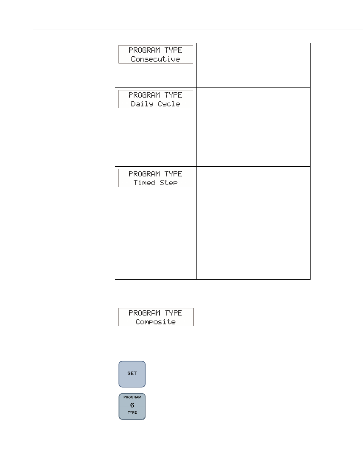
CVS4200 / BVS4300 Stationary Samplers
This option is used for discrete sampling
applications, to successively deposit one
sample to each of a programmed number of
containers on any given sample initiation.
The consecutive setting is programmable up
to 99 containers per sample initiation.
Allows the sampler to deposit equal sample
volumes into a predetermined number of
containers per programmed day. Each day
may have any number of samples taken,
dependent on the SAMPLE INITIATION
mode chosen. Deposits are made to as many
as 9 containers per day, to a cumulative total
of 24 containers. Timing is dependent on the
crystal-controlled Real Time Clock in the
controller. The first program day will be the
current day the programming is done.
This option will cause the sampler to step to
a new container regardless of the status of
the SAMPLE INITIATION setting. For
example, the actual sampling may be under
the control of a flowmeter and taking
samples based on the flow rate as
determined by pulses or 4-20mA input to the
controller. When the user-programmed
timed interval has elapsed, the controller will
step to a new container. The Timed Step c
be set for any interval up to 99 hours 59
minutes. Progress of the step timer can be
viewed by selecting View, Program Type
and pressing ENTER twice. Thus you may
view the step timing and the amount of time
until the next
step occurs.
an
52
7.6.6.2 PROGRAM TYPE - Composite
The following sequence of entries are made
on the Touchpad to describe how the
Sampler controller is to store the samples it
takes, in the hardware specified in its
configuration. The ACTIVE SETTINGS
are not being altered.
1. Press the SET key.
2. Press the PROGRAM TYPE key.
Page 61
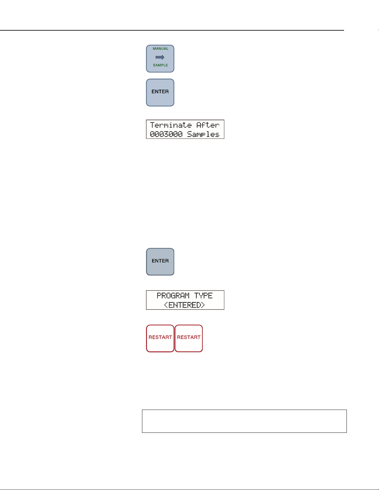
CVS4200 / BVS4300 Stationary Samplers
3. Press an ARROW key. Continue until
Composite is shown on the display (for
storage in single container).
4. Press the ENTER key.
The display will respond with the message
“Terminate After 0003000 Samples”. The
numerical value will be whatever value was
last placed in the controller’s memory,
usually after previous programming. To
keep the previous value, press ENTER, or,
to set a new value, use the ARROW keys to
advance the flashing prompt to the desired
location and replace the digits under the
prompt by using the digits (0-9) on the
Touchpad. Each new entry will
automatically advance the prompt to the next
location. In this way, the entire 7 digit
number can be changed. The ARROW keys
can be used to skip already correct digits, in
either direction.
When the 9 digit number is correctly
entered, press ENTER.
The display will echo the last entry with
PROGRAM TYPE <ENTERED>.
The controller has now been given a new
value for PROGRAM TYPE. The new
value resides in the NEW ENTRIES area of
the controller memory. To make these
changes active, press the RESTART key;
press it again to confirm your choice. The
controller will then be set to perform as a
Composite Sampler in conjunction with the
parameters programmed under the START
DELAY and SAMPLE INITIATION
variables.
Summary of Sequence:
SET, PROGRAM TYPE, ARROW(S), ENTER, #######, ENTER,
RESTART, RESTART.
53
Page 62

CVS4200 / BVS4300 Stationary Samplers
7.6.6.3 PROGRAM TYPE - Daily Cycle
The following sequence of entries are made
on the Touchpad to describe how the
Sampler controller is to store the samples it
takes, in the hardware specified in its
configuration. The ACTIVE SETTINGS are
not being altered.
1. Press the SET key.
2. Press the PROGRAM TYPE key.
3. Press an ARROW key. Continue until
Daily Cycle is shown on the display (for
storage in a single container or a multiple
container).
4. Press the ENTER key.
The display will respond with the message
“DAILY CYCLE Total Bottles ‘nn’”. The
two digits will be flashing as a prompt; they
can be changed using the arrow keys.
Press ENTER. The second line of the
display will change to show a day of the
week. The first day displayed will be the
day the programming is being done.
Following the day of the week will be a
flashing digit, which is prompting for a
numeric input. Using the number keys (0-9)
enter the number of bottles to be utilized on
the displayed day, to a maximum of 9 or the
total number of containers not yet allocated
from the array.
Press ENTER. This will register the value
for the displayed day and advance the
display to the next day. Again, enter a
number for that particular day, remembering
that only containers not previously allocated
can be chosen. If no change in the displayed
54
Page 63

CVS4200 / BVS4300 Stationary Samplers
value is required, the value has been
changed or the value is zero, pressing
ENTER will advance the day of the week.
Therefore...
Press ENTER. Repeat the above procedures
until all the required containers, on their
respective days, have been allocated, or the
7 days of the week are all selected. The total
number available is never allowed to be
more than the amount registered as the two
digit representation of the hardware
configuration in the “Total bottles 00” entry.
The display will echo the last entry with
PROGRAM TYPE <ENTERED>.
The controller has now been given a new
value for PROGRAM TYPE. The new
value resides in the NEW ENTRIES area of
the controller memory. To make these
changes active, press the RESTART key;
press it again to confirm your choice. The
controller will then be set to perform as a
Daily Cycle Sampler in conjunction with the
parameters programmed under the START
DELAY and SAMPLE INITIATION
variables.
Summary of Sequence:
SET, PROGRAM TYPE, ARROW(S), ENTER, ARROW(S), ENTER, #,
ENTER, #, ENTER, #, ENTER, #, ENTER, #, ENTER, #, ENTER, #,
ENTER, RESTART, RESTART.
7.6.6.4 PROGRAM TYPE - Daily Cycle for Dual Station
Dual Station – Flip Flop Application Only (Single Controller, Two Metering
Chambers)
The following sequence of entries are made
on the Touchpad to describe how the
Sampler controller is to store the samples it
takes, when the hardware specified is
configured to deliver Samples from two
separate sources. The ACTIVE SETTINGS
are not being altered.
55
Page 64

CVS4200 / BVS4300 Stationary Samplers
1. Press the SET key.
2. Press the PROGRAM TYPE key.
3. Press an ARROW key. Continue until
Daily Cycle is shown on the display.
4. Press the ENTER key.
The display will show the response “DAILY
CYCLE Total Bottles nn“. The two digits,
nn, will flash, indicating they can be
changed . In this application, the number of
bottles must be set to 24.
Press ENTER. The second line of the
display will change to show a day of the
week. The first day that shows will be the
day the programming is being done.
Following the day of the week will be a
flashing single digit, which is the prompt for
a numeric input. Using the number keys
(0-9) enter the number of bottles to be
utilized on the first day. In this application
this will be set to 2.
Press ENTER. This will register the value
for the displayed day and change that display
to show the next day. Again, enter a number
for that particular day, remembering that in
this application this will be set to 2. If no
change in the displayed value is required, the
value has been changed or the value is zero,
pressing ENTER will advance the day of the
week. Therefore...
Press ENTER. Repeat the above procedures
until all the required containers, on their
respective days, have been allocated, or the
7 days of the week are all selected. If all 7
days have been selected, then continuous
sampling will occur for up to 12 days.
56
Page 65

CVS4200 / BVS4300 Stationary Samplers
The display will echo the last entry with
PROGRAM TYPE <ENTERED>.
The controller has now been given a new
value for PROGRAM TYPE. The new
value resides in the NEW ENTRIES area of
the controller memory. To make these
changes active, press the RESTART key;
press it again to confirm your choice. The
controller will then be set to perform as a
Dual Station Sampler in conjunction with
the parameters programmed under the
START DELAY and SAMPLE
INITIATION variables.
Summary of Sequence:
SET, PROGRAM TYPE, ARROW(S), ENTER, ARROW(S), ENTER, #,
ENTER, #, ENTER, #, ENTER, #, ENTER, #, ENTER, #, ENTER, #,
ENTER, RESTART, RESTART.
7.6.6.5 PROGRAM TYPE - Consecutive
The following sequence of entries are made
on the Touchpad to describe how the
Sampler controller is to store the samples it
takes, in the hardware specified in its
configuration. The ACTIVE SETTINGS are
not being altered.
1. Press the SET key.
2. Press the PROGRAM TYPE key.
3. Press an ARROW key. Continue until
Consecutive is shown on the display (for
storage in single multiple container array).
4. Press the ENTER key.
57
Page 66

CVS4200 / BVS4300 Stationary Samplers
The display will show the response
“CONSECUTIVE Total Bottles nn”. The
two digits, nn, will be flashing, indicating
they can be changed.
Press ENTER. The display now reads “nn
bottles per Sample Cycle”. A previously set
value will be displayed. One of the digits is
flashing. Using the number keys (0-9), enter
the first digit of the number of bottles that
will be used at each sampling time
determined by the programming setting;
enter the number of samples to be taken at
each predetermined time. After the first
digit is entered, the second digit will flash
prompting for the remaining digit of the
entry. The sampler will repeat this quantity
each time the sampling is initiated, until the
“Total-Bottles” setting is reached.
Press ENTER. The display now reads
PROGRAM TYPE <ENTERED>.
The controller has now been given a new
value for PROGRAM TYPE. The new
value resides in the NEW ENTRIES area of
the controller memory. To make these
changes active, press the RESTART key;
press it again to confirm your choice. The
controller will then be set to perform as a
Consecutive Sampler in conjunction with the
parameters programmed under the START
DELAY and SAMPLE INITIATION
variables.
Summary of Sequence:
SET, PROGRAM TYPE, ARROW(S), ENTER, ENTER, ##, ENTER,
RESTART, RESTART.
58
Page 67
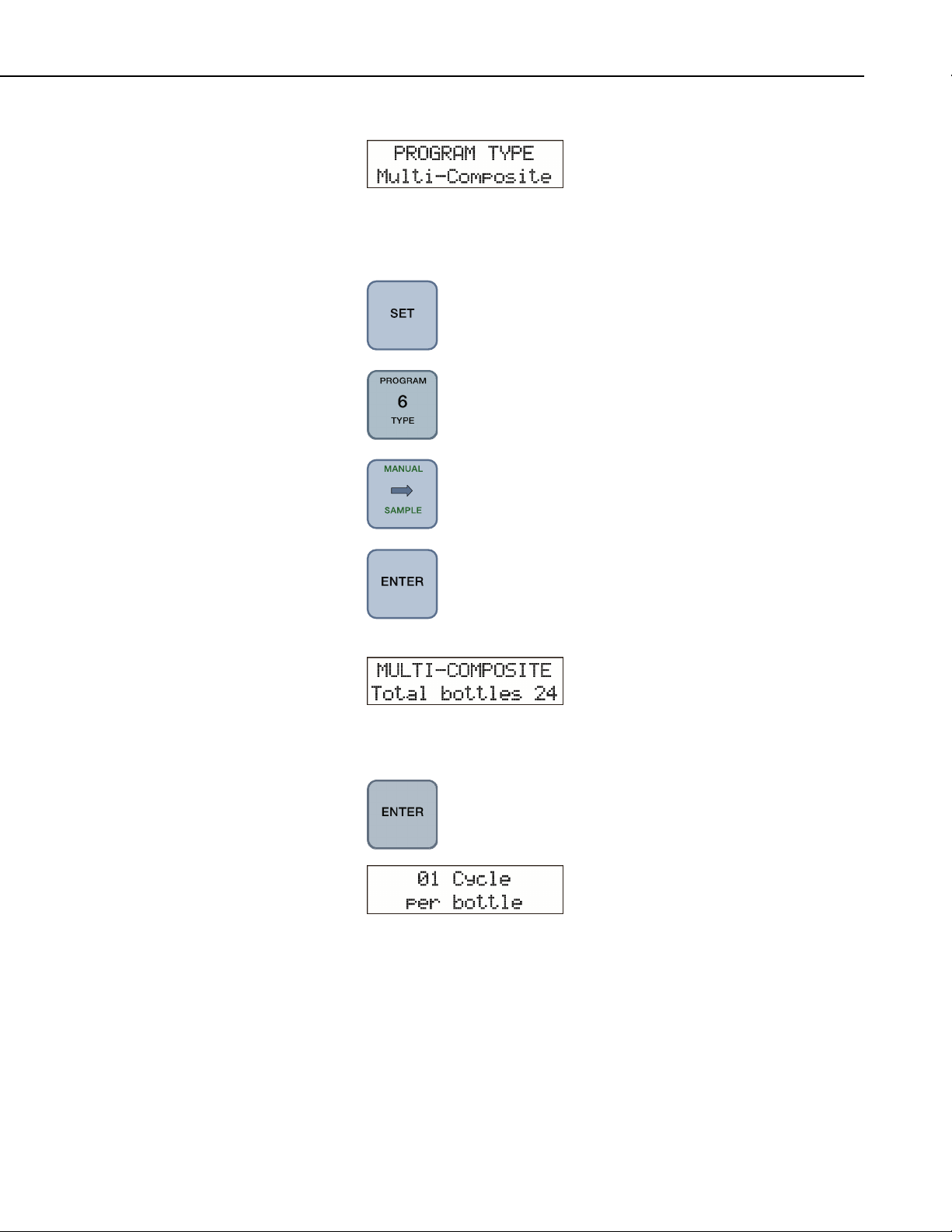
7.6.6.6 PROGRAM TYPE - Multi-Composite
CVS4200 / BVS4300 Stationary Samplers
The following sequence of entries are made
on the Touchpad to describe how the
Sampler controller is to store the samples it
takes, in the hardware specified in its
configuration. The ACTIVE SETTINGS
are not being altered.
1. Press the SET key.
2. Press the PROGRAM TYPE key.
3. Press an ARROW key. Continue until
Multi-Composite is shown on the display
(for storage in multiple container array).
4. Press the ENTER key.
The display will respond with the message
“MULTI-COMPOSITE Total Bottles nn”.
The two digits, nn, will be flashing,
indicating they can be changed by scrolling
with the arrow keys.
Press ENTER. The display now reads
“nn Cycles per bottle”. A previously set
value is displayed. One of the digits is
flashing, prompting for a numeric entry.
Using the number keys (0-9), select the
number of times the same bottle will be used
at the times determined by the programming;
enter the number of samples to be taken
before the stepper advances to the next
bottle. After the first digit is entered, the
second digit will flash, prompting for the
second digit of the entry. Each sample
placed in a bottle will be a complete cycle.
The program will repeat this action each
time the sampling is initiated, until the
“Total Bottles” setting is reached.
59
Page 68

CVS4200 / BVS4300 Stationary Samplers
Summary of Sequence:
SET, PROGRAM TYPE, ARROW(S), ENTER, ENTER, ##, ENTER,
RESTART, RESTART.
Press ENTER. The display now reads
PROGRAM TYPE <ENTERED>.
The controller has now been given a new
value for PROGRAM TYPE. The new
value resides in the NEW ENTRIES area of
the controller memory. To make these
changes active, press the RESTART key;
press it again to confirm your choice. The
controller will then be set to perform as a
Multi-Composite Sampler in conjunction
with the parameters programmed under the
START DELAY and SAMPLE
INITIATION variables.
7.6.6.7 PROGRAM TYPE - Timed Step
The following sequence of entries are made
on the Touchpad to describe how the
Sampler controller is to store the samples it
takes, in the hardware specified in its
configuration. The ACTIVE SETTINGS
are not being altered.
1. Press the SET key.
2. Press the PROGRAM TYPE key.
3. Press an ARROW key. Continue until
Timed Step is shown on the display (for
storage in multiple container array).
60
Page 69

CVS4200 / BVS4300 Stationary Samplers
4. Press the ENTER key.
Press ENTER. The display will show the
response “TIMED STEP Total Bottles nn”.
The two digits, nn, will be flashing,
indicating they can be changed by scrolling
with the arrow keys.
Press ENTER. The bottom line of the
display now reads “Step Intvl 00:00”. A
previously set value is displayed. One of
the digits is flashing, prompting for first
digit of a numeric input. The format is
HH:MM. Using the number keys (0-9),
enter the time interval the stepper MUST
advance, regardless of SAMPLE
INITIATION settings. The program will
repeat this action at the set interval except
during an ongoing sample cycle, when it
will advance the stepper after the sample
cycle is complete.
Press ENTER. The display now reads
PROGRAM TYPE <ENTERED>.
The controller has now been given a new
value for PROGRAM TYPE. The new
value resides in the NEW ENTRIES area of
the controller memory. To make these
changes active, press the RESTART key;
press it again to confirm your choice. The
controller will then be set to perform as a
Timed Step Sampler in conjunction with the
parameters programmed under the START
DELAY and SAMPLE INITIATION
variables.
Summary of Sequence:
SET, PROGRAM TYPE, ARROW(S), ENTER, ENTER, ####, ENTER,
RESTART, RESTART.
61
Page 70

CVS4200 / BVS4300 Stationary Samplers
7.6.7 Programming OTHER OPTIONS
7.6.7.1 OTHER OPTIONS Overview
SET or VIEW
This feature allows the user to SET or
VIEW the internal Real-Time clock of the
microprocessor.
This feature allows the user to SET or
VIEW the duration for which the sampler
will purge the intake line prior to drawing in
a sample to the chamber. The maximum
allowable setting is 99 seconds.
This feature allows the user to change how
the Pinch Valve will operate during
sampling cycles. The setting is dependant
upon which generation of sample the
controller is used on. If this is a new unit, the
Pinch Valve action will have been factory
set. Should the controller be used as a
retrofit into an older model, the setting may
have to be changed. If the sampler has a
Pinch Valve that squeezes shut the discharg
tube even during an inactive state, this
model is termed as normally closed. Shou
the tubing be shut only when the Pinch
Valve is energized, it is termed normally
open. This is the ONLY setting for the
PVS samplers.
This feature will enable or disable the ability
of the controller to cease operations wh
encounters repeated difficulties in the
drawing of samples. The controller norm
will attempt to obtain a valid sample by
repetition of its programming with extend
purge times and vacuum cycles, als
extending the time allowed for the
acquisition of the sample. When a sam
not obtained, this fact is noted in the
controller memory and the program resum
If after two (2) successive attempts have
failed, the controller will Shut Down, haltin
sampling until operator intervention clears
any reason for fault and RESTARTs th
program. This is not always a required
course of action. If FAULT SHUTDOWN is
disabled, the program will record all failures
to obtain samples a
sample initiation.
nd will wait until the next
o
e
ld
en it
ally
ed
ple is
es.
g
e
62
Page 71

VIEW ONLY
CVS4200 / BVS4300 Stationary Samplers
The controller will remember conditions
encountered during normal operation.
Reasons for premature ending of a set
program will also be saved in memory. By
VIEWing this feature, this information
be obtaine
d at the time the sampler is
can
checked.
Values retained by the controller to indicate
number of missed samples.
When equipped with the appropriate
hardware and with the controller running
proper program (Multi-Composite), the
the
current position of the distributor arm can b
determined by VIEWing this option. T
he
position information is relative to the
original position of the arm at the begin
ning
of the program start. Note: There is no
physical “Bottle 1”, any bottle can be
determined to be #
1 at the beginning of a
sample program.
The following selections are all available
under the maintenance heading and are all
for VIEWing only. To check any of these
values or perform any tests, press VIEW,
then OTHER OPTIONS. ARROW le
ft or
right as required until the flashing text
MAINTENANCE appears and press ENTER
Once more, ARROW left or right until t
desired fla
shing text appears, and press
he
ENTER.
Displays the microprocessor’s serial number.
e
.
Tests the controller’s on-board lithium
battery.
Tests the Touchpad keys.
Checks the main IC’s read / write integrity.
Technicians Only! Digital Feedback from
two on-board A/D channels
Channel 1: 4-20mA Input
.
Channel 2: Displays Float Voltage
63
Page 72
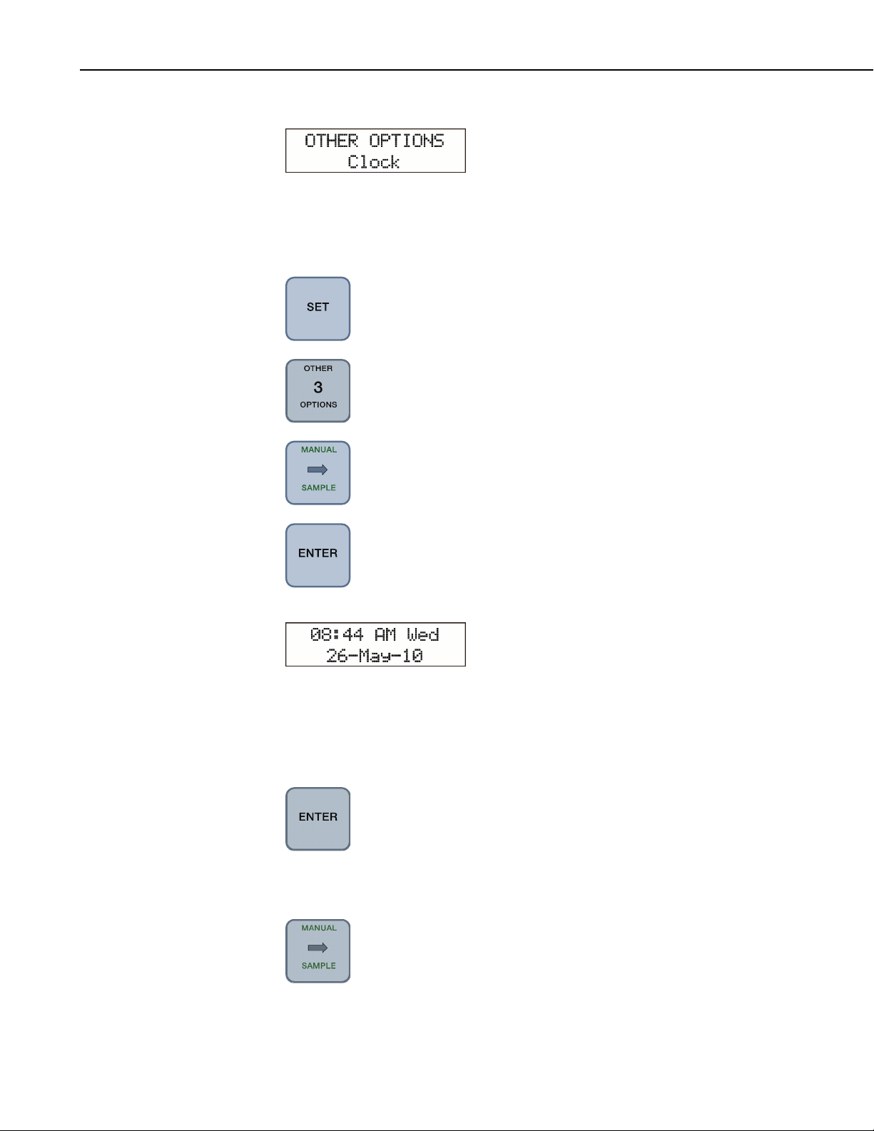
CVS4200 / BVS4300 Stationary Samplers
7.6.7.2 OTHER OPTIONS - Clock
The following sequence of entries are made
on the Touchpad to alter the Real Time
Clock, running internally in the controller,
which is the basis for all timed functions.
The ACTIVE SETTINGS are not being
altered and there are no NEW ENTRIES
generated.
1. Press the SET key.
2. Press the OTHER OPTIONS key.
3. Press an ARROW key. Continue until
Clock is shown on the display (for updating
the internal Real Time Clock).
4. Press the ENTER key.
The display shows a time / date response in
the form of “01:23 AM SUN 01-Jan-92”.
The flashing digits are changed, if necessary,
by use of the number keys (0-9) in the same
manner as a standard watch, in the HH:MM
format. Maximum values are 01 - 12 for the
hours pair and 00 to 59 for the minutes.
However, each digit is set separately.
Press ENTER. The display will shift its
flashing prompt to the AM/PM pair. Since
both characters are flashing, the selection is
made by use of the ARROW keys. The
selection cycles through AM and PM
repeatedly. Choose one.
Press ENTER. The display will shift its
flashing prompt to the three characters
forming the day of the week. Since all three
characters are flashing, the selection is made
by use of the ARROW keys. The selection
cycles through the 7 days. Choose one.
64
Page 73

CVS4200 / BVS4300 Stationary Samplers
Press ENTER. The bottom line of the
display shows a date in the format
DD-MM-YY. The DD pair is a pair of digits
with the normal range of 00 - 31. Set by
number keys (0-9) individually.
Press ENTER. The MM characters are set
using the ARROW keys for the choice of
one regular calendar month.
Press ENTER. The YY pair of digits are set
using the number keys again, corresponding
to the last two digits in the year. Set each
digit individually. Press ENTER. The date
as entered is now checked by the internal
clock. An invalid date will return the prompt
to the beginning of the date setting, after an
error message is displayed. It can then be
corrected and re-entered.
Summary of Sequence:
SET, OTHER OPTIONS, ARROW(S), ENTER, ##, ##, ENTER, ,
ARROWS, ENTER, ARROWS, ENTER, ##, ENTER, ARROWS,
ENTER, ##, ENTER.
7.6.7.3 OTHER OPTIONS - Purge Time
The display now reads CLOCK
<ENTERED>.
The controller has now been given a new
value for the REAL TIME CLOCK. The
new value is in use immediately, once set.
The following sequence of entries are made
on the Touchpad to describe how the
Sampler controller is to operate some of the
hardware specified in its configuration. The
ACTIVE SETTINGS are not being altered.
1. Press the SET key.
65
Page 74

CVS4200 / BVS4300 Stationary Samplers
2. Press the OTHER OPTIONS key.
3. Press an ARROW key. Continue until
Purge Time is shown on the display (for
operating time when the sampler is in the
purge mode of the Sample cycle,
pressurizing the inlet hose to clear it of
obstructions and fluid).
4. Press the ENTER key.
The display shows the response “PURGE
TIME seconds”. The first digit is flashing.
A previously set value may be displayed.
Using the number keys (0-9) enter the time
in seconds that will represent the basic purge
time. Multiples of this time may be used by
the controller to facilitate the removal of
obstructions in the inlet hose.
Press ENTER. The display now reads
PURGE TIME <ENTERED>.
The controller has now been given a new
value for PURGE TIME. The new value
resides in the NEW ENTRIES area of the
controller memory. To make these changes
active, press the RESTART key; press it
again to confirm your choice. The controller
will then be set to perform in conjunction
with the parameters programmed under the
START DELAY, SAMPLE INITIATION
and PROGRAM TYPE settings.
Summary of Sequence:
SET, OTHER OPTIONS, ARROW(S), ENTER, ##, ENTER, RESTART,
RESTART.
66
Page 75

7.6.7.4 OTHER OPTIONS - Pinch Valve
CVS4200 / BVS4300 Stationary Samplers
The following sequence of entries are made
on the Touchpad to describe how the
Sampler controller is to operate some of the
hardware specified in its configuration. The
ACTIVE SETTINGS are not being altered.
1. Press the SET key.
2. Press the OTHER OPTIONS key.
3. Press an ARROW key. Continue until
Pinch Valve is shown on the display.
4. Press the ENTER key.
The Pinch Valve option is for control of the solenoid activated pinch bar
determining vacuum / pressure modes in the sampler operation. This is a factor
usually set at the factory because it relates directly to the equipment
specification. It is alterable only to facilitate the use of the controller in plants
that have a variety of equipment configurations.
The display will show the response “PINCH
VALVE Normally Open / Closed”. All the
characters on the bottom line are flashing,
therefore the choice is made with the
ARROW keys. The choice is a toggle
between ‘Open’ and ‘Closed’. It represents
the state of the pinch valve when the
equipment is idle. Note: The sampler will
not perform properly if this setting is in
error.
Press ENTER. The display now reads
PINCH VALVE <ENTERED>.
67
Page 76
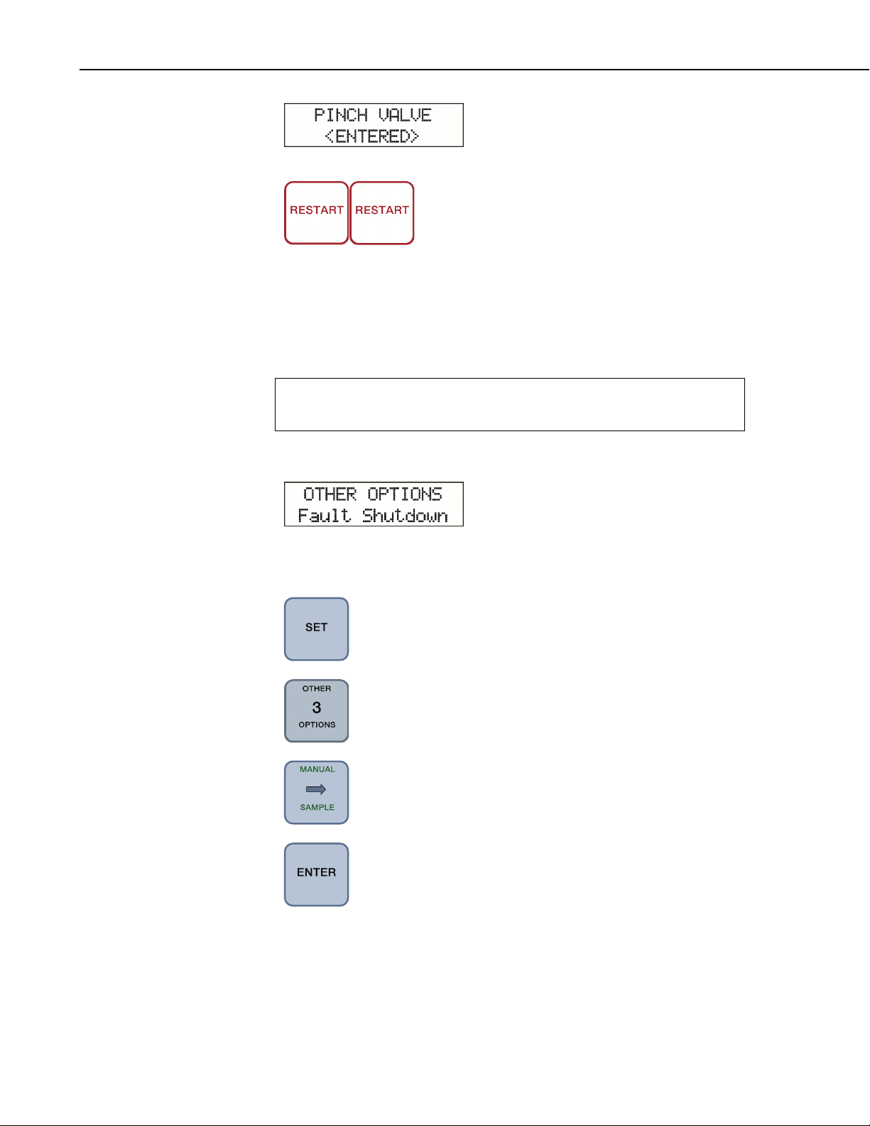
CVS4200 / BVS4300 Stationary Samplers
Summary of Sequence:
SET, OTHER OPTIONS, ARROW(S), ENTER, ARROW(S), ENTER,
RESTART, RESTART.
7.6.7.5 OTHER OPTIONS - Fault Shutdown
The controller has now been given a new
value for PINCH VALVE. The new value
resides in the NEW ENTRIES area of the
controller memory. To make these changes
active, press the RESTART key; press it
again to confirm your choice. The controller
will then be set to perform in conjunction
with the parameters programmed under the
START DELAY, SAMPLE INITIATION
and PROGRAM TYPE settings.
The following sequence of entries are made
on the Touchpad to describe how the
Sampler controller is to operate some of the
hardware specified in its configuration. The
ACTIVE SETTINGS are not being altered.
1. Press the SET key.
2. Press the OTHER OPTIONS key.
3. Press an ARROW key. Continue until
Fault Shutdown is shown on the display.
4. Press the ENTER key.
68
Fault Shutdown is used to control whether the sampler will cease taking
samples after a predetermined number of unsuccessful attempts.
Page 77

CVS4200 / BVS4300 Stationary Samplers
The display will show the response
“FAULT SHUTDOWN Enabled /
Disabled”. All the characters on the bottom
line are flashing, therefore the choice is
made with the ARROW keys. The choice
is a toggle between ‘Enabled’ or
‘Disabled’. If disabled, the controller will
make a lengthy attempt to obtain a sample,
then return control to the SAMPLE
INITIATION to try again. The controller
will accumulate a count of unsuccessful
(abandoned) attempts.
Press ENTER. The display now reads
FAULT SHUTDOWN <ENTERED>.
Summary of Sequence:
SET, OTHER OPTIONS, ARROW(S), ENTER, ARROW(S), ENTER,
RESTART, RESTART.
7.6.8 Viewing Information
7.6.8.1 Viewing Programmed Information
The controller has now been given a new
value for FAULT SHUTDOWN. The new
value resides in the NEW ENTRIES area of
To see current settings, press the VIEW button,
followed by the appropriate button as described on
its label.
The display will show current parameter settings,
beginning with the requested major category.
the controller memory. To make these
changes active, press the RESTART key;
press it again to confirm your choice. The
controller will then be set to perform in
conjunction with the parameters
programmed under the START DELAY,
SAMPLE INITIATION and PROGRAM
TYPE settings.
69
Page 78

CVS4200 / BVS4300 Stationary Samplers
START DELAY
SAMPLE INITIATION
Press the ENTER key. If more information is
available for a given parameter, it will be
displayed. Continue pressing ENTER until no new
information is presented. The display will
“wrap-around” to its first message. Where timing
or counting are used, active values will be shown
which can be used to monitor the progress of the
parameter.
Press the VIEW key.
Press the START DELAY key.
Sequence: VIEW, START DELAY, ENTER,
(ENTER).
Press the VIEW key.
PROGRAM TYPE
OTHER OPTIONS
Press the SAMPLE INITIATION key.
Sequence: VIEW, SAMPLE INITIATION,
ENTER, (ENTER).
Press the VIEW key.
Press the PROGRAM TYPE key.
Sequence: VIEW, PROGRAM TYPE, ENTER,
(ENTER).
Press the VIEW key.
Press the OTHER OPTIONS key.
Use ARROW keys to navigate to desired option
on the flashing display.
Press ENTER to view.
70
Available options are:
Clock - Time, Date (including Day)
Purge Time - Time in seconds
Pinch Valve - Normally Open or Closed
Fault Shutdown - Enabled or Disabled
Sampler Status - Error and system messages that
have been lost from the display by keyboard
entry.
Page 79

ACTIVE SETTINGS
CVS4200 / BVS4300 Stationary Samplers
Cycles Abandoned - Counter
Bottle Position - Relative position of distributor
Maintenance
- Serial Number - Unit identification number
- Analog Channels - /D output display,
- Backup Battery Test - Test of onboard
Lithium battery
– Memory Check - Test of controller
RAM/ROM locations
– Keypad Check - Test of Touchpad
(Under Maintenance, ARROW to selection, then
display with ENTER.)
Press the VIEW key.
Press the ACTIVE SETTINGS key.
The display will show “ACTIVE SETTINGS
‘ENTER’ to list”.
NEW ENTRIES
Press the ENTER key. The display will show the
START DELAY programming.
Continuously pressing the ENTER key will
display all of the active program selections and
return to the original display.
Sequence: VIEW, ACTIVE SETTINGS,
ENTER(S).
Press the VIEW key.
Press the NEW ENTRIES key.
If no “NEW ENTRIES” have been made, the
display will show “No New Entries View Active
Set”. If new parameters have been set, but the unit
hasn’t been RESTARTed, the display will show
“NEW ENTRIES ‘ENTER’ to list”. Press the
ENTER key. The display will show the START
DELAY programming. Continuously pressing the
ENTER key will display all of the program
selections, SUBSTITUTING new parameters where
they’ve been changed, and return to the original
display.
Sequence: VIEW, NEW ENTRIES, ENTER(S).
71
Page 80

CVS4200 / BVS4300 Stationary Samplers
7.6.8.2 Viewing Generated Information
The following sequence of entries are made on the Touchpad to examine the
sample information collected or generated by the controller and stored in its
memory.
SAMPLES TAKEN
REMAINING PULSES
Press the VIEW key.
Press the SAMPLES TAKEN key.
The display will show a count of all samples taken
during the current program. To make these changes
active, press the RESTART key; press it again to
confirm your choice. The controller will then wait
until the designated time before starting its
sampling program.
Press the VIEW key.
REMAINING TIME
Press the REMAINING PULSES key.
The display will show a countdown of incoming
pulses, decreasing from the programmed value.
Only available when either START DELAY or
SAMPLE INITIATION are using their Pulse
Input options or pulses generated by the 4-20mA
input option. The information is updated
continuously and can be left on the display as a
progress indicator.
Sequence: VIEW, REMAINING PULSES.
Press the VIEW key.
Press the REMAINING TIME key.
The display will show various time counters
dependent on the programming of the START
DELAY and SAMPLE INITIATION parameters.
Priority goes to START DELAY, which will show
an incrementing time for event related delays or
decrementing time for time related delays. The
display will then yield to SAMPLE INITIATION
for an elapsed time display for event related inputs
and Remaining Time display for time related
inputs.
72
Sequence: VIEW, REMAINING TIME.
Page 81

7.7 Test Procedure
1. Set volume control tube to 200 cc.
2. Set level probe 1” above bottom of volume control tube.
3. Turn on power. Place the “RUN/OFF” switch in the “RUN” position.
After an initial delay of 15 to 20 seconds, the display will show a two line
message, the top line displaying SAMPLER HALTED and an alternating
message on the second line displaying why the sampling procedure was
interrupted as well as the event time and date.
4. Enter the following sampling program:
a) Set purge time to 10 seconds. See OTHER OPTIONS
b) Set interval time to 2 minutes. See SAMPLE INITIATION
c) Set program type to composite. See PROGRAM TYPE
d) Set to terminate after 2 samples.
f) Press RESTART, RESTART (to confirm)
5. View the following displays:
a) Samples taken - should read 0
b) Remaining time - should be counting down from 2 minutes.
CVS4200 / BVS4300 Stationary Samplers
6. Sampling should begin when remaining time indicator reaches 0.
7. Upon completion of sample, view the following displays:
a) Samples taken - should read 1.
b) Remaining time - should be counting down from 5 minutes.
8. Press MANUAL PURGE. Press again to confirm.
9. Press MANUAL ADVANCE. Press again to confirm.
10. Press MANUAL SAMPLE. Press again to confirm.
11. If equipped with sample container full option, short circuit level probes in
container (no dangerous voltage present - 16 Vdc). The message
“SAMPLER HALTED External Stop” should appear on the display, the
bottom line flashing.
12. Press RESTART, RESTART, the message “RESTART <Completed>”
should appear on the display.
8. Troubleshooting
SAMPLER INOPERATIVE: Check supply voltage.
POWER ON BUT PUMP WILL NOT START: Check wiring from
sampler controller to pump. Ensure controller is properly connected
into harness.
a) Pump defective.
b) Sampler controller defective.
73
Page 82

CVS4200 / BVS4300 Stationary Samplers
SAMPLER WILL NOT TAKE TIMED SAMPLE:
a) Sampler controller defective.
SAMPLER WILL NOT INITIATE FROM AN EXTERNAL
CONTACT: Check wiring from terminal strip to sampler controller
plug. (Terminals 12 & 13)
a) Sampler controller is defective.
b) Sampler controller not programmed for External Contact input.
PUMP IS OPERATING, NO AIR PURGE OF INTAKE LINE: Check for
blockage of intake hose by removing hose from the metering chamber volume
control tube. Initiate manual sample and check for pressure/vacuum throughout
sample cycle.
a) If pressure/vacuum is present throughout sample cycle, intake hose is
plugged.
b) Pinch valve may not be closing the discharge hose with sufficient force
to ensure an adequate seal. Increase tension by tightening the lock nuts on
the pinch valve tension springs and/or replace discharge hose.
c) Check for disconnected air lines from pump to metering chamber.
d) Check for loose gland nuts.
e) Pump flapper valves defective.
PURGE CYCLE OPERATIVE, NO SUCTION: Pinch valve may not be
closing the discharge hose with sufficient force to ensure an adequate seal.
Increase tension by tightening the lock nuts on the pinch valve tension springs
and/or replace discharge hose.
a) Check air lines, metering chamber O-rings and fittings for leakage.
b) Solenoid valve clogged or not working.
c) Intake tube, not below water level.
SAMPLER HAS HAD AN “EXTERNAL STOP”: Contact not supplied via
terminal block.
a) Sample container Full Level Probe has been triggered.
LEVEL SENSING PROBE INOPERATIVE: Check wire contact
connections on volume control tube and level sensing probe. Check wiring to
the sampler controller plug.
a) Sampler controller defective
b) Coating on probe and/or Volume Control Tube.
9. Maintenance
NOTE
The following maintenance procedures should be performed at
regular intervals.
74
9.1 General Maintenance
1. Disconnect power.
2. Open metering chamber by removing wing nuts and chamber cover.
3. Clean volume control tube and level sensing probe with mild detergent.
Alternatively, exchange tube and probe with clean set. Do not use any
Page 83

cleaner which may be harmful to the metering chamber cover. Do not use
solvents such as acetone, benzene, carbon tetrachloride or lacquer thinners.
Grease and oil may be removed with kerosene or aliphatic naphtha (nonaromatic).
4. Check and clean O-rings in metering chamber cover.
Replace if damaged, worn or brittle.
5. Clean metering chamber using mild detergent.
Do not use any cleaner which may be harmful to the clear acrylic (for
example, petrochemical solvents, as noted above). Do not use abrasives or
“scouring” compounds.
6. Check discharge tubing for wear and replace as necessary.
7. Check pinch valve to ensure free movement.
8. If possible, run sampler through several sampling sequences in clean
water.
9.2 Maintenance of Refrigerator
CVS4200 / BVS4300 Stationary Samplers
9.2.1 Cleaning
CAUTION
Never use acids, chemical thinner, gasoline, benzene, or
the like for cleaning ANY part of the refrigerator. Boiling
water and benzene may deform or damage the plastic
parts.
1. Turn off power.
2. Remove containers and trays.
3. Wash interior liner with a warm solution of two tablespoons of baking
powder per quart of water. Rinse and wipe dry. Do not use soaps,
detergents, scouring powder, spray cleaners or the like on the interior liner
as it may cause odors in the refrigerator compartment.
4. Wipe the exterior surface with a soft cloth dampened with soapy water and
then dry with another soft cloth. Common appliance spray cleaner may be
used for exterior only. Use only mild soapy water to clean door gaskets.
9.2.2 Temperature Control
Refrigerator temperature can be regulated by adjusting the cold control. The
closer to “MAX” position, the lower the temperature. Recommended setting is
between “3 – 4”. However, refrigerator temperature will vary depending on the
ambient air temperature and on the frequency with which the door is opened.
This refrigerator may cycle on and off more frequently than regular size
refrigerators. This is normal because of its compactness.
75
Page 84

CVS4200 / BVS4300 Stationary Samplers
9.3 Testing System Vacuum
Using the (optional) built-in pressure/vacuum gauge, take a reading to ensure
system has no leaks. Optimal pressure is above 28 psi. Optimal vacuum should
be 12 psi or better.
If the system is not performing at its peak, try the following:
1. Check intake hose for leaks/kinks.
2. Check discharge tube, ensure it has no leaks and is in good shape.
3. Check all fittings to ensure they are tight.
4. Make sure when tightening and loosening the gland nuts on the top of the
metering chamber that the bottom nut is held secure and does not move on
the cover. Ensure the top nut is securely tightened, and use a wrench if
necessary.
5. If system is still not performing at its peak, inspect pump and all pump
tubing.
9.4 Controller Battery Repalcement Procedure
1. Make sure the controller is powered.
2. Remove Touchpad (clear) cover from the controller, remembering to
handle internal ribbon cable and connector with care.
3. Locate the battery holder on the normal left side of the circuit board. The
battery is a 1/2” cylinder about 1” in length. The positive (+) end of the
battery has a raised button. Note the button’s relative position in the
holder. It should be pointing away from the display side of the board.
4. Place new battery in holder, noting position of button with respect to the
polarity indicators in the holder.
5. Check battery status, as above. If necessary, locate small white button at
top of the control board (under display) and push to restore factory
defaults.
6. Replace cover securely and re-enter user settings.
9.5 Storage
If the sampler is not to be used for an extended period of time, store the unit in
an upright position in a warm, dry location. If the unit has an integral battery,
recharge the unit prior to storage.
76
Acceptable storage temperature: –30º to +60ºC (–22º to +140ºF)
Page 85

Appendix A. Principles of Operation
Switching Methods (Sinking / NPN)
LOAD
Sensor
Sinking (NPN) Switch
The Sinking method connects or switches one side of the load to the negative
(-) side of the power supply. The positive (+) side is connected directly to the
other side of the load as shown. “NPN” refers to the type of transistor used to
act as a switch in this type of solid-state sensor.
Switching Methods (Sourcing / PNP)
Sensor
LOAD
Sourcing (PNP) Switch
The Sourcing method connects or switches one side of the load to the positive
(+) side of the power supply. The negative (-) side is connected directly to the
other side of the load as shown. “PNP” refers to the type of transistor used to
act as a switch in this type of solid-state sensor.
A-1
Page 86

Appendix A. Principles of Operation
A-2
Page 87

Appendix B. Parts List
This is a partial list of most frequently requested CVS/BVS Sampler
replacement parts.
TABLE B-1. CVS/BVS Replacement Parts
Part No.
SAMPLE CONTAINERS
27956 27-03-07 2.5 Gallon (10 L) Glass with Teflon Cap
26900 22-10-32 Discrete Bottle Tray (24-Bottle x 0.5 L)
SINKER / STRAINER
26915 23-28-01-3/8 Sinker (Lead): 3/8 System
27820 23-28-01-5/8 Sinker (Lead): 5/8 System
26914 23-28-11 Sinker Strainer (Stainless Steel): 3/8 System
INTAKE TUBE
27166 PVC Standard: 3/8 in. ID (per foot)
26926 PVC Standard: 5/8 in. ID (per foot)
INTAKE TUBE WITH SINKER/STRAINER
27949 26-02-01 PVC: 3/8 in. ID: 25 ft with Lead Sinker
Old Part No.
(Prior to 8-1-11) D es cript ion
26925-L50-E1 26-02-01-050 PVC: 3/8 in. ID: 50 ft with Lead Sinker
26925-L100-E1 26-02-01-100 PVC: 3/8 in. ID: 100 ft with Lead Sinker
26925-L150-E1 26-02-01-150 PVC: 3/8 in. ID: 150 ft with Lead Sinker
26926-L25-E1 26-02-02 PVC: 5/8 in. ID: 25 ft with Lead Sinker
26926-L50-E1 26-02-02-050 PVC: 5/8 in. ID: 50 ft with Lead Sinker
26926-L100-E1 26-02-02-100 PVC: 5/8 in. ID: 100 ft with Lead Sinker
26926-L150-E1 26-02-02-150 PVC: 5/8 in. ID: 150 ft with Lead Sinker
DISCHARGE TUBE
26898 26-03-01 Discharge Tubing (Latex): 3/8" ID: 3 Ft
27951 26-03-06 Discharge Tubing (Latex): 5/8" ID: 3 Ft
B-1
Page 88

Appendix B. Parts List
METERING CHAMBER
26906 24-01-01 Metering Chamber (Acrylic): 3/8 System, 0.5 L
27941 24-01-02 Metering Chamber (Acrylic): 5/8 System, 0.5 L
28459 24-01-03 Metering Chamber (Acrylic): All Systems, 1000 cc
26905 24-01-08 Metering Chamber (Pyrex): 3/8 System, 0.5 L
28238 24-01-09 Metering Chamber (Pyrex): 3/8 System, 1 L
27942 24-01-10 Metering Chamber (Pyrex): 5/8 System, 500 cc
28239 24-01-11 Metering Chamber (Pyrex): 5/8 System, 1000 cc
28391 50-21-01 Metering Chamber Cover: 3/8 Delrin
28392 50-21-04 Metering Chamber Cover: 5/8 Delrin
28393 50-21-06 Metering Chamber Cover: 3/8 Teflon
28394 50-21-07 Metering Chamber Cover: 5/8 Teflon
26919 23-03-04 Volume Control Tube: 5/8 System, 0.5 L
27939 23-37-02 Liquid Sensing Rod for Metering Chamber: 1 L
26908 28-05-02 O-ring: Metering Chamber (Buna-N)
26910 28-05-03 O-ring: Barrier Valve (Viton)
VACUUM PUMP
28333 32-01-01 Vacuum Pump – 12 Vdc
28009 32-02-05 Pump Assembly (including solenoids and fixtures) – 12 Vdc
26895 32-08-10 Brush & Lead Wire Kit (for 32-01-01)
REFRIGERATOR
28010 32-03-12 Large Refrigerator - Glass Door (Discrete & Dual Station)
DISTRIBUTOR / STEPPER
28287 32-04-01 Distributor (Teflon)
28011 32-05-01 Stepper Motor
28296 32-06-01 Distributor (PVC)
ENCLOSURE
B-2
28170 22-13-02 BVS Cabinet (Powder coated steel)
28175 22-15-00 BVS Cabinet #14 304/2B SS Unfinished
Page 89

Appendix B. Parts List
OTHER COMPONENTS
28005 30-DC-MFCB Multi-Function Input Controller (12 Vdc)
28012 50-02-13 Pinch Valve Assembly (12 Vdc All Systems)
27826 28-11-41 Quick Connector Assembly 3/8 in. System
27998 28-11-42 Quick Connector Stem (SS): 1/2 in.
MANUAL Hard Copy of Manual
26950 Battery: 12 Vdc, 17 Ah, Sealed Rechargeable
28337 55-15-23 Power Supply: 13.6 Vdc, 10.5 A, 110 to 240 Vac
B-3
Page 90

Appendix B. Parts List
B-4
Page 91

Page 92

Campbell Scientific Companies
Campbell Scientific, Inc. (CSI)
815 West 1800 North
Logan, Utah 84321
UNITED STATES
www.campbellsci.com • info@campbellsci.com
Campbell Scientific Africa Pty. Ltd. (CSAf)
PO Box 2450
Somerset West 7129
SOUTH AFRICA
www.csafrica.co.za • cleroux@csafrica.co.za
Campbell Scientific Australia Pty. Ltd. (CSA)
PO Box 8108
Garbutt Post Shop QLD 4814
AUSTRALIA
www.campbellsci.com.au • info@campbellsci.com.au
Campbell Scientific do Brasil Ltda. (CSB)
Rua Apinagés, nbr. 2018 ─ Perdizes
CEP: 01258-00 ─ São Paulo ─ SP
BRASIL
www.campbellsci.com.br • vendas@campbellsci.com.br
Campbell Scientific Canada Corp. (CSC)
11564 - 149th Street NW
Edmonton, Alberta T5M 1W7
CANADA
www.campbellsci.ca • dataloggers@campbellsci.ca
Campbell Scientific Centro Caribe S.A. (CSCC)
300 N Cementerio, Edificio Breller
Santo Domingo, Heredia 40305
COSTA RICA
www.campbellsci.cc • info@campbellsci.cc
Campbell Scientific Ltd. (CSL)
Campbell Park
80 Hathern Road
Shepshed, Loughborough LE12 9GX
UNITED KINGDOM
www.campbellsci.co.uk • sales@campbellsci.co.uk
Campbell Scientific Ltd. (France)
3 Avenue de la Division Leclerc
92160 ANTONY
FRANCE
www.campbellsci.fr • info@campbellsci.fr
Campbell Scientific Spain, S. L.
Avda. Pompeu Fabra 7-9, local 1
08024 Barcelona
SPAIN
www.campbellsci.es • info@campbellsci.es
Please visit www.campbellsci.com to obtain contact information for your local US or international representative.
 Loading...