

Page 1

CSBUOY-DT
Revision: 11/08
Copyright © 2002-2008
Campbell Scientific, Inc.
Page 2

Warranty and Assistance
The CSBUOY-DT is warranted by CAMPBELL SCIENTIFIC, INC. to be
free from defects in materials and workmanship under normal use and service
for twelve (12) months from date of shipment unless specified otherwise.
Batteries have no warranty. CAMPBELL SCIENTIFIC, INC.'s obligation
under this warranty is limited to repairing or replacing (at CAMPBELL
SCIENTIFIC, INC.'s option) defective products. The customer shall assume
all costs of removing, reinstalling, and shipping defective products to
CAMPBELL SCIENTIFIC, INC. CAMPBELL SCIENTIFIC, INC. will
return such products by surface carrier prepaid. This warranty shall not apply
to any CAMPBELL SCIENTIFIC, INC. products which have been subjected
to modification, misuse, neglect, accidents of nature, or shipping damage. This
warranty is in lieu of all other warranties, expressed or implied, including
warranties of merchantability or fitness for a particular purpose. CAMPBELL
SCIENTIFIC, INC. is not liable for special, indirect, incidental, or
consequential damages.
Products may not be returned without prior authorization. The following
contact information is for US and International customers residing in countries
served by Campbell Scientific, Inc. directly. Affiliate companies handle
repairs for customers within their territories. Please visit
www.campbellsci.com to determine which Campbell Scientific company
serves your country.
To obtain a Returned Materials Authorization (RMA), contact CAMPBELL
SCIENTIFIC, INC., phone (435) 753-2342. After an applications engineer
determines the nature of the problem, an RMA number will be issued. Please
write this number clearly on the outside of the shipping container.
CAMPBELL SCIENTIFIC's shipping address is:
CAMPBELL SCIENTIFIC, INC.
RMA#_____
815 West 1800 North
Logan, Utah 84321-1784
For all returns, the customer must fill out a “Declaration of Hazardous Material
and Decontamination” form and comply with the requirements specified in it.
The form is available from our website at
completed form must be either emailed to shanna@campbellsci.com
to 435-750-9579. Campbell Scientific will not process any returns until we
receive this form. If the form is not received within three days of product
receipt or is incomplete, the product will be returned to the customer at the
customer’s expense. Campbell Scientific reserves the right to refuse service on
products that were exposed to contaminants that may cause health or safety
concerns for our employees.
www.campbellsci.com/repair
. A
or faxed
CAMPBELL SCIENTIFIC, INC. does not accept collect calls.
Page 3

CSBUOY-DT Shipping List
Items packaged with the CSBUOY-DT for shipment include:
• CSBUOY-DT
• Solar panel with mounting brackets and cable
• Lid
• Instrument housing with antenna hole plug
• Float with two (2) eye-bolts
• Float plug unscrewed
• Instrument shroud
• Instrumentation mounting bracket
• CR206
• Antenna with cable
• Relay with cable
• 7 AH battery with cable
• Sensors
• Dissolved oxygen/temperature probe
• Wiper brush
• Two (2) large desiccant packs
• Humidity card
• CSBUOY-DT manual
• CR206 manual/CD-ROM
Page 4

This is a blank page.
Page 5

Special Operating Notes
1. Check the shipping list in the front of the manual and make sure that all
the parts checked off the list are with the CSBUOY-DT. If any parts are
missing, please contact Campbell Scientific, Inc. (435) 753-2342.
2. When connecting the battery avoid shorting the battery to the CR206.
3. Damage to the electronics will occur if moisture builds up inside the
CSBUOY-DT instrument housing.
4. The Heyco pressure fittings seal the cable entry points against water
intrusion. These fittings must be tightened periodically to ensure a tight
fit.
Page 6

This is a blank page.
Page 7

CSBUOY-DT Table of Contents
PDF viewers note: These page numbers refer to the printed version of this document. Use
the Adobe Acrobat® bookmarks tab for links to specific sections.
1. Introduction...............................................................1-1
1.1 Specifications........................................................................................ 1-1
2. CSBUOY-DT Description..........................................2-1
2.1 System Components .............................................................................2-1
2.2 Standard Sensors................................................................................... 2-1
2.3 Communication Options....................................................................... 2-2
2.4 Power Supply........................................................................................ 2-2
3. CSBUOY Installation ................................................3-1
3.1 Site Selection........................................................................................3-1
3.2 CSBUOY-DT Assembly ...................................................................... 3-1
4. Communication.........................................................4-1
4.1 Direct Connection to PC....................................................................... 4-1
4.1.1 Device Configuration Utility Software Installation................... 4-1
4.1.2 RF401 Connection...................................................................... 4-1
4.2 CSBUOY-DT as a Wireless Sensor ..................................................... 4-1
5. Maintenance..............................................................5-1
5.1 Instrumentation Maintenance ............................................................... 5-1
5.1.1 Batteries ...................................................................................... 5-1
5.1.2 Desiccant..................................................................................... 5-1
5.1.3 Sensor Maintenance.................................................................... 5-1
5.1.4 Calibration .................................................................................. 5-2
i
Page 8

This is a blank page.
Page 9

Section 1. Introduction
The CSBUOY-DT is programmed to communicate directly with a personal
computer operating Device Configuration Utility software and/or as a wireless
sensor providing data for other Campbell Scientific dataloggers. A 5-watt
solar panel is used to trickle charge the battery.
1.1 Specifications
General
CSBUOY-DT Weight: 37 lbs
Environment: Freshwater and brackish ponds and small lakes;
quiet water marine (no wave or tidal activity)
Buoy
Material: Polyethylene
Dimensions: 47” (119 cm) height, 30” (76 cm) float diameter
Instrument Housing: 6.36” (16.15 cm) OD, 6” (15.24 cm) ID
Wireless Transmitter
Storage: 512 Kbytes Flash Final Storage; data format is 4
Radio Type: RF401, 916 MHz Spread Spectrum Transceiver
Average Continuous
Current Drain: 20 mA radio always on, 2.2 mA radio in 1 s duty
Antenna
Frequency: 900 Mhz
Distance: 5000 ft (1524 m) assuming line of sight
Gain: 0 dBd
Length: 3.25” (8.26 cm)
bytes per data point (table-based); 60 Kbytes Flash
(OS/program)
cycle, 0.6 mA radio in 8 s duty cycle
1-1
Page 10

Section 1. Introduction
Solar Panel
Dissolved Oxygen/Water Temperature Probe
Typical Peak Power: 5 W
Voltage @ Peak Power: 17.1 Vdc
Current @ Peak Power: 300 mA
Dimensions: 9.45” (24 cm) length, 10.4” (26.4 cm) width
Membrane Type: PTFE (Teflon®)
Output at 100% Saturation: 24 to 42 mV
Temperature Range: 0° to 50°C
Accuracy: +/- 2%
Response Time: 2 minutes to reach 90% of final reading
Minimum Water Flow Rate: 2” (5 cm) per second across membrane
Material: Delrin®
PRT: 100 Ohm
Power Requirements
for Agitator Brush: 12 Vdc, 1.1 A
1-2
Page 11
Section 2. CSBUOY-DT Description
The CSBUOY-DT is designed to eliminate the use of hard-wire cable to
connect the dissolved oxygen and water temperature sensors with the
datalogger (CR510, CR10X, CR23X, CR800, CR850, CR1000, CR3000).
Operation is simplified through a modular design, prewired sensors, and
preprogrammed interface. This manual covers installation, communication,
and maintenance.
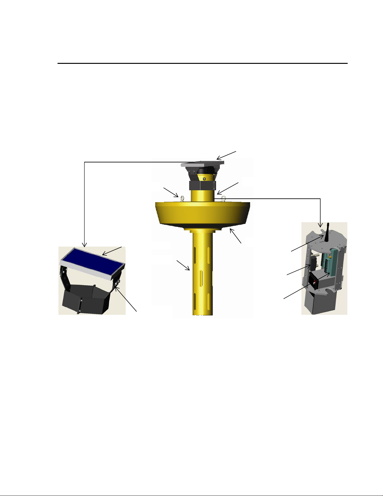
2.1 System Components
Mooring Eyebolts
5 W Solar Panel
Sensor Shroud
Solar Panel
Mounting
Brackets
5 W Solar Panel
Instrument Housing
Float
Antenna
Relay
CR206
2.2 Standard Sensors
Prewired sensors include:
• Dissolved Oxygen
• Water Temperature
• Battery Voltage
• Wiper Brush
• Relative Humidity (optional)
2-1
Page 12

Section 2. CSBUOY-DT Description
2.3 Communication Options
• Direct RS-232 Connection to PC
• RF401 Spread Spectrum Radio Connection to PC
• Rf401 Spread Spectrum Radio Connection to Datalogger (CR510,
CR10X, CR23X, CR800, CR850, CR1000, CR3000)
2.4 Power Supply
• 7 Amp/hr 12 VDC Rechargeable Battery
• 5 W Solar Panel Trickle Charger
2-2
Page 13

Section 3. CSBUOY Installation
3.1 Site Selection
The site should represent the general area being measured. Placement should
allow the buoy to float freely without obstruction from the bottom of the water
compound being monitored. The buoy solar panel should not have any
obstruction from full sunlight. Keep away from overhanging trees or other
obstructions. The solar panel should be angled towards the south to maximize
full solar capabilities.
3.2 CSBUOY-DT Assembly
CR206 Relay DO/WT Probe Wiper Solar Panel Batt
Battery- Black
Battery+ Red
Charge- Black
Charge+ Red
1 Brown
Battery+ 2+ White
SW Batt 3+ Black
G 4 Clear
G Blue
SE1 Red - DO Sig+
GND Black - DO Sig-
SE2 Green - PRT V1
GND White - PRT G
EX1 Purple Vex (2.5v)
G Clear - Shield
Ensure that each wire is in the proper place on the CR206. Connect the battery
cable to the battery. Using a wrench, tighten the Heyco Pressure fitting to
ensure a watertight seal around the sensor cables exiting the instrument
housing. Insert the instrument mounting bracket into the instrument
housing, paying particular attention that the cable are not pinched. Tighten the
instrument housing lid.
With a wrench, tighten the vent plug into the float.
Attach the solar panel to the solar panel brackets. Tighten the connection
with the thumb screws.
3-1
Page 14

Section 3. CSBUOY Installation
Secure the mooring eye-bolts to a mooring line or the anchor eye-bolt to the
anchor line to secure placement of buoy in desired location.
3-2
Page 15

Section 4. Communication
The CSBUOY-DT can be used as a stand-alone monitoring system that
communicates directly with the PC, or as a wireless sensor that is integrated
with other Campbell Scientific dataloggers (CR510, CR10X, CR23X, CR800,
CR850, CR1000, CR3000) with table-based operating systems using the
PakBus communication protocol.
4.1 Direct Connection to PC
In order to communicate with the CSBUOY-DT directly from the PC:
1. Device Configuration Utility software must be installed in the PC.
2. An RF401 Spread Spectrum Radio must be connected via com port to the
PC.
3. The RF401 and CSBUOY-DT Transceiver (CR206) must be configured to
communicate with each other (refer to RF401 and CR206 manuals).
4.1.1 Device Configuration Utility Software Installation
Refer to the Device Configuration Utility Manual for installation an d operation
instructions.
4.1.2 RF401 Connection
Refer to the RF401 Manual for configuration instructions.
4.2 CSBUOY-DT as a Wireless Sensor
A CSBUOY-DT acting as a wireless sensor can communicate with a CR800,
CR850, CR1000, or CR3000 datalogger using the GetVariable instruction.
With a CR10X, CR510, or CR23X, the program instruction P193 is used.
These instructions open the communication between CSBUOY-DT and the
datalogger allowing data to be sent and received. In addition to this
instruction:
1. The datalogger requires a RF401 Spread Spectrum Radio configured with
a datalogger CDSC current port configuration.
2. The RF401 connected to the datalogger and the CSBUOY-DT must be
configured with the same radio address, net address and hopping
sequence.
4-1
Page 16

Section 4. Communication
‘CR1000 Series Datalogger
Public Result, Remotedata (3)
DataTable (Test,1,-1)
DataInterval (0,60,Sec,10)
Sample (3,Remotedata(),FP2)
EndTable
Alias Remotedata(1) = DOmV
Alias Remotedata(2) = WaterTempC
Alias Remotedata(3) = BatteryVolt
BeginProg
Scan (30,Sec,0,0)
GetVariables (Result,ComSDC7,0,1,0000,0,“Public”,“Buoydata()”,Remotedata(),3)
‘where 1 is the PakBus address of the CSBUOY-DT
CallTable Test
NextScan
EndProg
Programming Examples
The following example allows the CR1000 to communicate with one
CSBUOY-DT.
This example allows the CR10X to communicate with one CSBUOY-DT.
;{CR10X-PB}
;
*Table 1 Program
01: 30 Execution Interval (seconds)
1: Batt Voltage (P10)
1: 1 Loc [ Batt ]
2: PakBus - Wireless Network Master (P193)
1: 1 Number of Remotes
2: 10 First Remote Address
3: 0 Time Into Transmit Interval (sec)
4: 300 Transmit Interval (sec, 0 = use execution interval)
5: 0 Transmit Delay Between Remotes (sec)
6: 5 Swath to Receive
7: 7 First Loc for Data Received [ RID_1 ]
8: 0 Swath to Send
9: 18 First Loc to Send [ Scratch ]
10: 2 Result Code Loc [ RCom_1 ]
3: Data Table (P84)
1: 0 Seconds into Interval
2: 300 Seconds Interval
3: 0 (0 = auto allocate, -x = redirect to inloc x)
4: Hist Table Name
4-2
Page 17

4: Sample (P70)
1: 13 Reps
2: 1 Loc [ Batt ]
For further instruction on programming, please refer to the CR10X manual.
Section 4. Communication
4-3
Page 18

Section 4. Communication
4-4
Page 19

Section 5. Maintenance
The CSBUOY-DT has been engineered to provide many years of reliable
service. However, periodic maintenance is required to help ensure that the
system performs up to its potential. Equipment must be in good operating
condition, which requires a program of regular inspection and maintenance.
Routine and simple maintenance can be accomplished by the person in charge
of the CSBUOY-DT.
5.1 Instrumentation Maintenance
The instrumentation requires a minimum of routine maintenance. A few
preventative maintenance steps will optimize battery life and decrease the
chances of system failure.
5.1.1 Batteries
The CSBOUY-DT has been programmed to record battery voltage. This will
allow the user to determine how long a fresh battery will last. The
CSBUOY-DT is supplied with a fresh 12 VDC, 7.0 Ahr rechargeable battery.
This battery is continually recharged by the 5-watt solar panel mounted on top
of the instrument housing. Be aware of battery voltage that consistently
decreases over time, which indicates a failure in the charging circuitry.
5.1.2 Desiccant
Damage to the CR206 and wiring panel will occur if high moisture levels
inside the CSBOUY-DT instrument housing are not corrected. Enclosure
humidity is monitored by a humidity indicator card provided with the
CSBUOY-DT. It can also be more accurately monitored using the 10162
Enclosure Humidity Sensor, which is an optional sensor that can be purchased
with the CSBUOY-DT. The CSBOUY-DT is programmed to provide data
from this sensor.
Regardless if the humidity sensor or the humidity indicator card is used to
monitor humidity inside the instrument housing, desiccant packs should be
replaced when relative humidity inside the instrument housing exceeds 35%.
5.1.3 Sensor Maintenance
Sensor maintenance should be performed at regular intervals, depending on the
desired accuracy and the conditions of use. A suggested maintenance schedule
is outlined below.
First week
• Check the wiper brush to ensure it is removing biological growth from the
dissolved oxygen sensor membrane.
• Check the Heyco pressure seals to ensure a tight fit.
5-1
Page 20

Section 5. Maintenance
• Check inside of the instrument housing to ensure against water leakage.
Any leakage will also be indicated by increase in humidity inside the
instrument housing.
• Check the dissolved oxygen probe to ensure a correct reading.
Each month
• Check wiper brush to ensure it is removing biological growth from the
dissolved oxygen membrane.
• Check humidity indicator card (or humidity readings from sensor).
Replace desiccant pack and tighten Heyco pressure fittings if needed.
• Check dissolved oxygen readings; calibrate probes if required.
Every Six Months
• Replace dissolved oxygen probe membrane and refill electrolyte solution.
Calibrate dissolved oxygen probe.
Each Year
• Check cable for rodent or environmental damage.
• Replace humidity indicator card if necessary.
Every Three to Five Years
• Check anode and cathode metals inside dissolved oxygen probe. Replace
• Replace 10162 Humidity Sensor (if being used).
General Maintenance
• An occasional cleaning of the glass on the solar panel will improve its
• Check sensor leads and cables for cracking, deterioration, and rodent
• Check the CSBUOY-DT float, instrument housing, instrument shroud, and
5.1.4 Calibration
if corrosion is extensive.
efficiency.
damage.
cap for structural damage, poor fittings, loose fittings.
5-2
The multiplier is used to calibrate the dissolved oxygen probe. The calibration
of the probe when using it as a wireless sensor in conjunction with another
datalogger is then a function of the datalogger. Generally this is made simple
by using the feature of PondView software. When using the CSBUOY-DT as
a stand-alone direct to PC connection then the multiplier is changed in the
Device Configuration Utility software.
Page 21

5.1.4.1 Air Calibration
1. Place the dissolved oxygen probe in the air, shaded from the sun. Wait for
the measurement reading to stabilize. This may take 15 minutes or more.
2. Determine the air temperature (use the temperature reading from the
probe; this is found on the Device Configuration Utility screen) and the
barometric pressure(preferred) or elevation.
3. Using the calibration chart determine the oxygen concentration in the air.
4. Use the following equation to calculate the multiplier:
M = P/R
M = Multiplier
P = Concentration in PPM of the air (from calibration chart).
R = The signal output in mV of the dissolved oxygen probe.
5. Enter the multiplier in Device Configuration Utility or LoggerNet from the
calculated number.
5.1.4.2 Hand Calibration
Section 5. Maintenance
1. Use a hand-held dissolved oxygen meter to determine the correct
concentration of dissolved oxygen in the water (the accuracy of the
method will be dependent upon the accuracy of the hand held device).
2. Use the following equation to calculate the multiplier:
M = D/R
M = Multiplier
D = measured dissolved oxygen in PPM.
R = The signal output in mV of the dissolved oxygen probe.
3. Enter the multiplier in Device Configuration Utility or LoggerNet from the
calculated number.
5-3
Page 22

Section 5. Maintenance
This is a blank page.
5-4
Page 23

This is a blank page.
Page 24

Campbell Scientific Companies
Campbell Scientific, Inc. (CSI)
815 West 1800 North
Logan, Utah 84321
UNITED STATES
www.campbellsci.com
info@campbellsci.com
Campbell Scientific Africa Pty. Ltd. (CSAf)
PO Box 2450
Somerset West 7129
SOUTH AFRICA
www.csafrica.co.za
cleroux@csafrica.co.za
Campbell Scientific Australi
PO Box 444
Thuringowa Central
QLD 4812 AUSTRALIA
www.campbellsci.com.au
info@campbellsci.com.au
Campbell Scientific do Brazil Ltda. (CSB)
Rua Luisa Crapsi Orsi, 15 Butantã
CEP: 005543-000 São Paulo SP BRAZIL
www.campbellsci.com.br
suporte@campbellsci.com.br
Campbell Scientific Canada Corp. (CSC)
11564 - 149th Street NW
Edmonton, Alberta T5M 1W7
CANADA
www.campbellsci.ca
dataloggers@campbellsci.ca
Campbell Scientific Ltd. (CSL)
Campbell Park
80 Hathern Road
Shepshed, Loughborough LE12 9GX
UNITED KINGDOM
www.campbellsci.co.uk
sales@campbellsci.co.uk
Campbell Scientific Ltd. (France)
Miniparc du Verger - Bat. H
1, rue de Terre Neuve - Les Ulis
91967 COURTABOEUF CEDEX
FRANCE
www.campbellsci.fr
info@campbellsci.fr
Campbell Scientific Spain, S. L.
Psg. Font 14, local 8
08013 Barcelona
SPAIN
www.campbellsci.es
info@campbellsci.es
Please visit www.campbellsci.com to obtain contact information for your local US or International representative.
a Pty. Ltd. (CSA)
 Loading...