

Page 1

CS725 Snow Water
Equivalency Sensor
Revision: 8/12
Copyright © 2010-2012
Campbell Scientific, Inc.
Page 2

Page 3

Warranty
“PRODUCTS MANUFACTURED BY CAMPBELL SCIENTIFIC, INC. are
warranted by Campbell Scientific, Inc. (“Campbell”) to be free from defects in
materials and workmanship under normal use and service for twelve (12)
months from date of shipment unless otherwise specified in the corresponding
Campbell pricelist or product manual. Products not manufactured, but that are
re-sold by Campbell, are warranted only to the limits extended by the original
manufacturer. Batteries, fine-wire thermocouples, desiccant, and other
consumables have no warranty. Campbell's obligation under this warranty is
limited to repairing or replacing (at Campbell's option) defective products,
which shall be the sole and exclusive remedy under this warranty. The
customer shall assume all costs of removing, reinstalling, and shipping
defective products to Campbell. Campbell will return such products by surface
carrier prepaid within the continental United States of America. To all other
locations, Campbell will return such products best way CIP (Port of Entry)
INCOTERM® 2010, prepaid. This warranty shall not apply to any products
which have been subjected to modification, misuse, neglect, improper service,
accidents of nature, or shipping damage. This warranty is in lieu of all other
warranties, expressed or implied. The warranty for installation services
performed by Campbell such as programming to customer specifications,
electrical connections to products manufactured by Campbell, and product
specific training, is part of Campbell’s product warranty. CAMPBELL
EXPRESSLY DISCLAIMS AND EXCLUDES ANY IMPLIED
WARRANTIES OF MERCHANTABILITY OR FITNESS FOR A
PARTICULAR PURPOSE. Campbell is not liable for any special, indirect,
incidental, and/or consequential damages.”
Page 4

Assistance
Products may not be returned without prior authorization. The following
contact information is for US and international customers residing in countries
served by Campbell Scientific, Inc. directly. Affiliate companies handle
repairs for customers within their territories. Please visit
www.campbellsci.com to determine which Campbell Scientific company serves
your country.
To obtain a Returned Materials Authorization (RMA), contact CAMPBELL
SCIENTIFIC, INC., phone (435) 227-9000. After an applications engineer
determines the nature of the problem, an RMA number will be issued. Please
write this number clearly on the outside of the shipping container. Campbell
Scientific's shipping address is:
CAMPBELL SCIENTIFIC, INC.
RMA#_____
815 West 1800 North
Logan, Utah 84321-1784
For all returns, the customer must fill out a "Statement of Product Cleanliness
and Decontamination" form and comply with the requirements specified in it.
The form is available from our web site at www.campbellsci.com/repair. A
completed form must be either emailed to repair@campbellsci.com or faxed to
(435) 227-9106. Campbell Scientific is unable to process any returns until we
receive this form. If the form is not received within three days of product
receipt or is incomplete, the product will be returned to the customer at the
customer's expense. Campbell Scientific reserves the right to refuse service on
products that were exposed to contaminants that may cause health or safety
concerns for our employees.
Page 5

Table of Contents
PDF viewers: These page numbers refer to the printed version of this document. Use the
PDF reader bookmarks tab for links to specific sections.
1. Introduction.................................................................1
2. Specifications .............................................................1
3. Wiring........................................................................... 2
4. Connecting the CS725 to a Computer ......................2
5. Terminal Setup for RS-232 Communications........... 3
6. Communicating with the CS725 ................................4
6.1 General.................................................................................................4
6.2 Auto Baud Rate Detection....................................................................4
6.3 Main CS725 Menu ...............................................................................4
6.4 Detailed Main Menu Command Information .......................................5
6.5 Hidden Commands.............................................................................17
6.6 Datalogger Talk Through Mode.........................................................17
7. Parts Overview..........................................................17
8. Site Selection Details................................................18
8.1 Collimator ..........................................................................................19
8.2 Soil Moisture Considerations .............................................................19
8.3 Obtaining Site Qualifying Counts ......................................................19
9. Mounting.................................................................... 22
9.1 Mounting Options ..............................................................................23
10. Final Parameter Setup .............................................. 25
11. Firmware Update (using command .0xw) ...............27
12. System Power Requirements and
Recommendations .................................................29
12.1 Non Solar-Powered Sites ...................................................................29
12.2 Solar-Powered Sites ...........................................................................29
i
Page 6

Table of Contents
13. Detailed Measurement Theory .................................29
14. Maintenance and Assembly .....................................31
15. Datalogger CRBasic Programming .........................33
15.1 Extended Data Output (.flla) Command ............................................ 33
15.2 Short Form Data Output (.fs) Command ........................................... 36
Figures
4-1. CS725 connection to DB9F-TERM .................................................... 3
7-1. CS725 components............................................................................ 18
9-1. Position of 1/4‐20 mounting holes .................................................. 23
9-2. Example of wall/plate mounting........................................................ 24
9-3. Horizontal pipe mounting shown with the 27412 Mount Kit............ 25
13-1. Gamma histogram ............................................................................. 30
14-1. CS725 main body.............................................................................. 31
14-2. CS725 inner tube shown.................................................................... 32
14-3. CS725 cutout view ............................................................................ 32
14-4. CS725 with top cap removed............................................................. 33
Tables
8-1. Collimator Guidelines ....................................................................... 19
8-2. Potassium (K) Count Range Guideline.............................................. 21
8-3. Thallium (Tl) Count Range Guideline............................................... 22
ii
Page 7

Cautions / Safety Notes
• If you are unable to determine that your structure or mounting method is
suitable for the CS725 sensor, please contact an expert or professional who
can assist you in determining the structural mounting requirements for
your installation of the CS725.
• Always ensure that the collimator is secured to the structure with the long
safety cable.
• Do not disassemble the CS725 without consulting the factory first. The
CS725 contains a fine bead-like insulation material called Aerogel
Nanogel. The material is manufactured by Cabot Corporation. Proper
MSDS sheets and instructions should be obtained prior to opening the
CS725.
• The collimator is heavy and proper handling procedures need to be
followed when handling the part.
• Never force the connector on to the CS725. If the connector does not
easily fit into place then it is likely misaligned.
Abbreviations/Syntax
K The Element Potassium
SWE Snow Water Equivalency
Tl The Element Thallium
[] Square brackets identify a typed command. The content inside the
brackets is what is sent or typed and the brackets are excluded.
<> Denotes a special key for example <Enter> represents the Enter Key.
Page 8

Page 9

CS725 Snow Water Equivalency Sensor
1. Introduction
The CS725 sensor is primarily designed to measure the SWE (Snow Water
Equivalency) in a snow pack.
The CS725 obtains a measurement by passively monitoring the attenuation of
naturally existing electromagnetic radiation, due to the presence of potassium
and thallium. As snow accumulates on top of the ground, the CS725 measures
a decrease in the normal background radiation levels. The higher the water
content, the higher the attenuation of the radiation.
The CS725 has several characteristics that make it an excellent sensor for SWE
measurement applications.
• The sensor is non-contact. It is installed simply by mounting it above the
snow surface.
• The measurement is passive.
• Its performance is not affected by adverse weather conditions.
• The sensor’s measurement covers a large surface area. Typically 50 to
• It is effective with any type of snow or ice.
Proper operation of the CS725 is dependent on suitable amounts of potassium
(K) and thallium (Tl) being present in the ground. Since the radiation levels
will vary from site to site, the CS725’s performance can also be site specific.*
*No special licenses or precautions are required to install or operate the CS725.
2. Specifications
Power Requirements: 11 to 15 Vdc
Power Consumption: 180 mA
Measurement Time: Continuous, 24 hours/day
Output Format: RS-232 (1200 to 115200 bps)
Default is 9600 bps
2
(538 to 1076 ft2) when mounted 3.0 m above the ground.
100 m
Measurement Range: 0 to 600 mm (0 to 23.6 in) of water equivalency
Accuracy: ±15 mm (±0.6 in) for 0 to 300 mm (0 to 11.8 in)
±15% at 300 to 600 mm (11.8 to 23.6 in)
Resolution: 1 mm (0.004 in)
1
Page 10

CS725 Snow Water Equivalency Sensor
Coverage Beam Angle: 60°
Operating Temperature: -40° to +40°C
Maximum Cable Length: 30 m (95 ft) (9600 bps or less)
Cable Type: 4 conductor, 2-twisted pair,
22 AWG, Santoprene jacket
Dimensions
(Without Collimator)
Length: 62 cm (24.4 in)
Diameter: 12.7 cm (5 in)
Weight
Main Body: 9.0 kg (20 lbs)
Collimator: 25 kg (55 lbs)
Total: 34 kg (75 lbs)
3. Wiring
The wiring for the CS725 connector-cable assembly is as follows:
Color Function Connection
Black Power Ground System Ground and/or RS-232 Receiver
Ground
(Pin 5 of a computer (DTE) DB-9 connector)
Red +12VDC Power Power Source
Green RS-232 (Sensor
Output)
White RS-232 (Sensor Input) Recorder/Reader RS-232 Output
Clear Shield Shield/Earth Ground
Recorder/Reader RS-232 Input
(Pin 2 of a computer (DTE) DB-9 connector)
(Pin 3 of a computer (DTE) DB-9 connector)
4. Connecting the CS725 to a Computer
The CS725 can communicate directly to PC using a terminal program such as
Hyperterminal. To provide a DB9 connection between the CS725 and a PC’s
RS-232 port, the DB9F-TERM interface PCB is used. The DB9F-TERM is
shipped with the CS725. The following diagram demonstrates how to connect
the CS725 to the DB9F-TERM.
2
Page 11

CS725 Snow Water Equivalency Sensor
FIGURE 4-1. CS725 connection to DB9F-TERM
When connecting the CS725 to a computer, a power source is required to
power the CS725. A good quality regulated +12 Vdc power source should be
used such as a bench power supply or a +12 Vdc battery. It is recommended to
disconnect the cable from the CS725 while terminating the cable connections.
After the connections are verified, the connector can be reconnected to the
CS725.
5. Terminal Setup for RS-232 Communications
The following are the settings required for the terminal program to
communicate with the CS725. Typical programs include Hyperterminal or
Procomm.
Baud Rate: 9600 (Default)
Data Bits: 8
Parity: None
Stop Bits: 1
Flow Control: None
Local Echo: Enabled
Terminal Mode: ANSI
Send Line Ends
with Line Feeds: Disabled
3
Page 12

CS725 Snow Water Equivalency Sensor
When the power is applied to the CS725 or the connector is plugged in, the
CS725 will output the following message on the RS-232 port on power up:
GMONIII Scionix 3x3 V4f_13u SN: 9999
Where:
GMONIII: Is the original sensor Identifier (now known as CS725)
Scionix 3x3: Is the Gamma Detector Type
V4f_13u: Is the Firmware Software Revision
SN: 9999 Is the sensor’s serial number
6. Communicating with the CS725
6.1 General
Immediately after power on, the CS725 will default to a baud rate defined by
the “DefaultBaudRate” parameter. This is normally 9600 bps and it is
recommended to leave the setting at 9600 bps.
The escape key resets the current command line being entered into the CS725.
If you are communicating with the CS725 using another intelligent device, the
commands should be preceded with the ESC character to ensure more reliable
operation.
The commands to the CS725 are case sensitive.
All commands are terminated by the enter key or <CR> character.
6.2 Auto Baud Rate Detection
If the terminal speed does not match the CS725’s baud rate, the startup
message will either be absent or garbled. The CS725 does support an Auto
Baud Rate Detection feature. In order to synchronize the CS725 with the
terminal, one can type the letter ‘U’ in uppercase followed by a period “.” and a
carriage return. This will trigger the auto-baud system, and the CS725 will
adjust its baud rate to the baud rate of the terminal. The period “.” followed by
a carriage return (CR) launches the Main menu once the baud rates are
synchronized.
NOTE
Any changes to the CS725 baud rate must be accounted for in
the datalogger program.
4
6.3 Main CS725 Menu
The Main menu can be prompted by sending a period “.” followed by the enter
key
.<Enter>
Page 13

CS725 Snow Water Equivalency Sensor
The menus can be switched between English and French. To change the
language setting, key the command .L<Enter>. This will allow the selection of
either English or French. The English version of the Main menu is as follows:
*** LIST OF COMMANDS ****
[.l] Language (French or English)
[.h] Read the current live histogram
[.hp] Display the K and Tl peak positions from the live histogram
[.hl] Display the current histogram in log scale
[.hr] Display results after completionof a manual measurement (histogram,
position and #counts K and TI).
[.e] Same as <h> command , but erases histogram at end of operation
[.a] Special command: define start/stop time limits for one measurement
[.t] Display temperature data in °C
[.d] Display date and time
[.dd] Modify date and time
[.hd] Read back histograms from EPROM according to selected dates
[.f] Read back measurement results from EPROM according to dates
[.fl] Read back the current day measurement results
[.flla] Read back last calculated line result
[.fs] Read back calculated line result in short form ? (Time and EENS
only)
[.p] Display Parameter menu
[.s] Display status and current measurement information
[.0xps] Parameters save to file function
[.0xpr] Parameters recovery from file function
[%Rhard]/[%Rboot] Restart software processor/reboot firmware
[UU] CS725/terminal synchronizing sequence for rates other than 9600 bps
6.4 Detailed Main Menu Command Information
1. [.l]
The [.l] command is used to set the language setting to either French or
English.
The following menu is activated once the [.l] command is received:
[0] Francais
[1] English
Type the number 0 for French or the number 1 for English followed by
<Enter>.
5
Page 14

CS725 Snow Water Equivalency Sensor
2. [.h]
The [.h] command is used to obtain the current histogram results. This
information would normally be used for diagnostics or by a user who
requires an analysis of the gamma radiation spectrum. The counts for
1024 bin values are returned in this command. The format is as follows:
12<CR><LF> This line represents the counts for BIN#1
345<CR><LF> This line represents the counts for BIN#2
333<CR><LF> This line represents the counts for BIN#3
.
.
.
30<CR><LF> This line represents the counts for BIN#1024
3. [.hp]
The [.hp] command is used to obtain the current bin positions for the Tl
and K peaks. In general the Tl peak should be near 438 and the K peak
should be near 245. It is important for the software to find the peaks
properly in order to obtain proper SWE measurements.
In most cases, the sensor must be monitoring for at least two minutes. It
may take as long as a full hour if the radiation counts are very low.
Once the command is typed, the following is immediately displayed:
This operation may take 1-2 minutes
Once the calculation has been completed, the values are displayed. Even
under ideal conditions, the values are allowed to vary from the target
values. If the value does vary by more than 30 BINS, then there may be
issues with the sensor finding the proper peaks. The displayed values are
formatted as follows:
Tl (nom = 438) K (nom = 245)
435.4 244.7
6
Page 15

CS725 Snow Water Equivalency Sensor
4. [.hl]
The [.hl] command is used to obtain a graphical representation of the
current histogram results. This information would normally be used for
diagnostics or by a user who requires an analysis of the gamma radiation
spectrum. The command produces a log scale graph as follows:
5. [.hr]
The [.hr] command is used to verify radiation counts in manual mode. The
[.hr] command would normally be used in the process of qualifying a site
for adequate background radiation counts and is used in conjunction with
the [.a] command. See the [.a] command for details.
Please note that the [.hr] command can take several minutes to complete.
When the command is entered, the [.hr] command will immediately report
the duration of the current manual count time as follows:
-Elapsed time,current histo : 00:03:59 (HH:MM:SS)
Wait for the calculation to complete...
There will then be a pause that can take several minutes. After the pause,
a histogram will be output followed by the radiation count summary. The
summary will report three lines; the duration of the counting, the position
of the potassium peak and its processed count value, the position of the
thallium peak and its processed count value. The output format after the
histogram is as follows:
7
Page 16

CS725 Snow Water Equivalency Sensor
-Elapsed time,current histo : 00:03:59
Pos K = 240.4; Pos Tl = 427.5;
Cnt K = 003679.8; Cnt Tl = 000088.3;
6. [.a]
The [.a] command is used to set the start and stop times for a specified
measurement interval. This command could be used in the process to
qualify a site for appropriate amounts of background radiation.
This parameter is only made use of when the CS725 is in the manual
mode. The CS725 is placed in in the manual mode by entering the
Parameter menu [.p] and set parameter 19 to 1 for manual mode.
Once the parameter is set (the setting will be saved automatically), use the
.a command to specify the delay and duration in seconds. For qualifying a
site, it is recommended that the sensor be setup in the desired location and
the delay of 5 be used with a duration of 3600 seconds (1 hour) as a
minimum. The example below shows the syntax for the recommended
delay and duration for the manual measurement:
(Delay should be larger or equal to 5s)
Format =>Delay Duration
=>5 3600<Enter>
After completion, the [.hr] command can then be used to view the results
in detail. If the CS725 is placed in Auto or HCalib mode, the following
message will be printed:
This function should be called in manual mode only.
7. [.t]
The [.t] command is used to read the internal temperature sensor of the
CS725 (degrees Celsius). This feature is mainly used for diagnostics to
apply temperature compensations. Temperature measurements are made
inside of the internal electronics and on the surface of the gamma detector
crystal. The output format is as follows:
temp crystal:23 temp electronics:27
8. [.d]
The [.d] command is used to display the current date and time. The
display order is:
Day of Month/Month/Year <4 space characters>
Hour:Min:Sec<CR><LF>
The format is as follows: 16/09/2009 15:00:20
The CS725 does not perform any time zone or daylight-savings time
correction. This can be done in the datalogger.
8
Page 17

CS725 Snow Water Equivalency Sensor
9. [.dd]
The [.dd] command is used to set the current date and time. The following
menu is activated from the [.dd] command:
Modify that date? :
[1] aaaa: 2009
[2] mm: 09
[3] jj: 16
[4] hh: 15
[5] mm: 01
[6] ss: 54
[0] Exit
[99] Accept selection
To Modify: [parameter number, space, new value,CR]
The current values at the time the .dd command was entered are displayed.
To change a value, enter the parameter number followed by the new value
and then the enter key. To change the minute to 02 from 01, one would
enter the following:
5<Space>02<Enter>
After new values are entered, the long format of the date/time will be
displayed once the 99 is entered to accept the selection.
99<enter>
and the CS725 will print
16/09/2009 15:02:54
The time should be set for the purpose of control and analysis of the data.
It can be local time, GMT, or any other. The CS725 does not perform any
time zone or Daylight-Savings time correction.
The time can also be updated using the long command line format of the
date/time as follows:
.dd dd/mm/yy hh:mm:ss<enter>
or
.dd<space>dd/mm/yyyy<space>hh:mm:ss<enter>
Exampe:
.dd 05/11/2010 10:46:00<enter>
or
.dd<space>05/11/2010<space>10:46:00<enter>
Use a .d command to confirm the time has been set.
9
Page 18

CS725 Snow Water Equivalency Sensor
10. [.hd]
The [.hd] command is used to read back histograms from EPROM
according to selected dates. When the [.hd] command is entered, the
following menu is displayed:
Histograms: Select first day to retrieve
Modify that date? :
[1] aaaa: 2009
[2] mm: 09
[3] jj: 16
[.] Exit
[99] Accept selection
To Modify: [parameter number, space, new value,CR]
This is the first day that the historic histograms will be displayed from.
Once the start date is entered and accepted, the menu will prompt for an
end date as follows:
Histograms: Select last day to retrieve
Modify that date? :
[1] aaaa: 2009
[2] mm: 09
[3] jj: 16
[.] Exit
[99] Accept selection
To Modify: [parameter number, space, new value,CR]
After the last day or end date is accepted, the Histograms will be reported
in the following format. For each day requested the date is placed first
followed by the 1024 bin values.
10
22/09/2009 23:59:50 Time stamp of first requested day
29 This line represents the counts for BIN#1
52 This line represents the counts for BIN#2
67 This line represents the counts for
BIN#3
.
.
7 This line represents the counts for
BIN#1024
23/09/2009 23:59:50 Time stamp of second requested day
359 This line represents the counts for BIN#1 for
the second day
No more histogram data available in this time window.
Page 19
CS725 Snow Water Equivalency Sensor
11. [.f]
The [.f] command is used to read back measurement results from EPROM
according to selected dates.
Four lines will be output for every day requested where monitoring
occurred. See the section under [.fl] for output details.
The date selection procedure is the same as the [.hd] command.
12. [.fl]
The [.fl] command is used to read back the current day readings, which
can be up to four detailed measurement results. The output will consist of
four lines as follows:
1 2 3 4 5 6 7 8 9 10 11 12 13 14 15 16 17 18 19
01/10/2009 00:59: 1 2 52913 11342 5716 393 343 411 18 18 64 120 9 24 24 13 4.2 12.98
01/10/2009 06:59: 1 2 57037 13168 6074 371 309 392 18 18 77 110 7 19 24 13 4.2 12.23
01/10/2009 12:59: 1 2 69645 13016 6415 371 360 375 18 18 27 165 2 8 24 12 3.2 12.23
01/10/2009 18:59: 1 2 58951 14218 6280 359 292 382 18 18 83 032 1 16 24 13 3.2 12.23
The format is the date and time stamp followed by the following numbers:
1. Date and Time Stamp
2. Station ID
3. CS725’s Serial number
4. K counts total uncorrected
5. K counts total corrected (this value is used in the actual SWE
calculations)
6. Tl counts total corrected (this value is used in the actual SWE
calculations)
7. SWE value generated from K
8. Radio generated from K and Tl
9. SWE value generated from Tl
10. Soil Moisture values generated from K
11. Soil Moisture values generated from Tl
12. Soil Moisture values generated from K and Tl
13. Precipitation index: Flag indication recent snowfall or rain
14. Crystal temperature min
15. Crystal temperature max
16. Total number of histogram blocks used for the analysis
17. Displacement of the K peak from its nominal position (in bins)
18. Statistical significance of the SWE Tl measurement
19. Power input voltage at the CS725 (after protection diode drop)
13. [.flla]
The [.flla] command is used to read back last calculated line results. The
output will be in the same format as [.fl] command.
08/11/2010 11:59: 1234 1023 637733 485431 24425 0 -706 0 -47 68 -47 0
26 27 24 -1 1.3 12.05
11
Page 20

CS725 Snow Water Equivalency Sensor
14. [.fs]
The [.fs] command is used to read back last results in short form. The
short form consists of the date and time of the readings and the SWE
values in millimeters. The format is as follows:
DD/MM/YYYY HH:MM:SS SWE_K SWE_TL
01/10/2009 06:59:50 123 129
15. [.p]
The [.p] command is used to display the Parameter Setup menu. The
Parameter Setup menu is as follows:
[1] Station ID (Max 8 characters; ex: Gouin_21) : CS725_#1
[3] Time of start of measure (relative to GMON 00h RTC) : 00
[4] Delay after start of measure for data transmission (secs.)
0=> No transmission) : 0
[5] Frequency of data transmission: 0 => every 24 h
1 => every 6 h : 1
[6] GMON height above ground in centimeters : 300
[7] Observed position for the K line on the histogram : 245
[8] Collim (1: Collimator installed; 0: no collimator) : 1
[9] Nominal soil humidity in %weight,(min: 1, max: 150) : 25
[10] Estimated soil humidity in %weight (min: 1, max: 150)
for HCalib mode : 27
[11] NoK : 230000
[12] NooK (residual K counting) Default:0 : 0
[13] N0Tl : 41000
[14] n00Tl ( residual Tl counting) : 0
[16] SN Threshold for the snow cover : 5
[17] Baud rate for scheduled transmissions : 9600
[18] Number of hours per partial histo (hours),(1,2,3,or 6) : 1
[19] Manual mode (1); Auto mode (0) ; HCalib mode (2); : 1
[0] Quit without saving the new parameters on EPROM
[99] Save parameters on EPROM
To modify: [parameter number, space, new value,CR]
=>
12
To modify: [parameter number, space, new value,CR]
[1] Station ID
This is a user-selectable value that can be used to identify a CS725.
The Station ID is part of the output information for certain data
formats. The value is a string (maximum 8 alphanumeric characters).
Avoid using spaces as this can cause problems when parsing the data
output strings.
[1] Station ID (Max 8 characters; ex: Gouin_21) :CS725_#1
[3] Time of start of measure (relative to CS725 00h RTC)
This defines the hour at which a 24-hour period of measurements will
begin. This number is relative to the time set in the internal Real
Time Clock (RTC) by the user. The format is an integer, with values
from 0 to 24. This also defines the time a 24-hour measurement will
end. This end time is 10 seconds before the start of measure.
Page 21

CS725 Snow Water Equivalency Sensor
[4] Delay after start of measure for data transmission (secs.)
This defines the time at which the calculated results from the previous
24-hour period will be automatically transmitted from the serial port.
It is recommended to set the value to zero in order to disable the
automatic transmission of data via the serial port.
This is in seconds after the start of the new 24-hour period. The
minimum value should be 300 in order to allow the calculations to
complete. The maximum value is 23 h 55 min (86100 seconds) in the
case of one transmission every 24 hours, and 5 h 55 min (21,300
seconds) in the case of one transmission every 6 hours. This option is
set with parameter [5]. There will be four transmissions spaced by 6
hours.
[5] Frequency of data transmission: 0 => every 24 h 1 => every 6 h
This configures the Automatic Data output, and allows output every
24 h or every 6 h.
This parameter is a flag to instruct the software to transmit the
calculated data once a day (value = 0), or once every 6 hours (value =
1). All data output configured with this parameter is relative to the
“Time of start of measure” parameter.
It should be noted that the daily output transmission consists of four
averaged values from four overlapping 24-hour periods, which are
offset by 6 hour intervals.
When the every 6 hours mode is selected, the same four periods will
be transmitted, but one at the time, as they become available.
[6] CS725 height above ground in centimeters
Enter the actual installed height of the CS725 above the ground,
measured from the bottom of the main body, not from the collimator.
This is a parameter used in the SWE calculation to account for the
absorption of gamma rays in air.
[7] Observed position for the K line on the histogram
This is a parameter used by the peak finding and identifying
algorithm, in order to properly frame the search window. It is the bin
position at which the
40
K isotope peak is observed on the histogram.
This is to allow for small shifts in the detector gain. The format is an
integer with a value equal or close to 245.
[8] Collim (1: Collimator installed; 0: no collimator)
This parameter indicates whether the collineator is being used with
the CS725. Be sure to select the appropriate configuration, as this
does affect the proper function of the CS725.
[9] Nominal soil humidity in % weight (min: 1, max: 150)
The value (site specific) for the soil humidity is used to account for
the amount of water in the soil. This quantity is defined for a unit
volume of soil as
100 (mass of water/mass of dry soil)
13
Page 22

CS725 Snow Water Equivalency Sensor
Once the soil is frozen, this quantity is relatively constant. The
format is an integer between 1 and 150.
[10] Estimated soil humidity in % weight (min: 1, max: 150) for
HCalib mode
This is a site-specific parameter used for the auto calibration of the
CS725. The auto calibration mechanism calculates baseline values
for the coefficients n0Ke and n0Tl. These coefficients correspond to
the integrated rates of gamma rays seen by the detector for the K peak
(n0Ke) and the Tl peak (n0Tl) with zero moisture. The HCalib
parameter is normally the humidity measured by some other means at
the time of the calibration in order to account for this humidity in the
soil when the parameters n0Ke and n0Tl are evaluated. The format is
an integer.
[11] N0K
This site specific parameter is used in the calculation of the SWE. It
represents the integrated gamma ray count rate for the potassium
40
K
isotope peak, with no snow cover and dry soil. This number is, of
course, dependent upon the level of natural radio-activity of the soil
at the installation site. It can only be calculated on the site. The autocalibration method is a tool to obtain the first estimate of that
parameter . The format is an integer.
[12] N00K (residual K counting) Default: 0
This is a parameter to account for the gamma rays coming from
above the surface of the snow. This is typically a very small number
(less than 225), and affects the SWE evaluation only under very high
SWE conditions (above 300 mm). This value is normally obtained
after a full season of operation and can only be determined by
comparing the CS725 data with manual measurements.
NOTE
This value should not be altered above 225 unless extensive site
data analysis has been completed and Campbell Scientific has
been consulted.
[13] N0Tl
This site-specific parameter is used in the calculation of SWE. It
represents the integrated gamma ray count rate for the thallium
isotope peak, with no snow cover and dry soil. This number is, of
course, dependent upon the level of natural radio-activity of the soil
at the installation site. It can only be calculated on the site. The autocalibration method is a tool to obtain the first estimate of that
parameter. The format is an integer.
[14] N00Tl ( residual Tl counting)
This is a parameter to account for the gamma rays coming from
above the surface of the snow. It affects the SWE evaluation only
under high SWE conditions (above 300 mm). This value is normally
determined after the first year of operation. The value is typically
1900 or less.
208
Tl
14
Page 23

CS725 Snow Water Equivalency Sensor
[16] SN Threshold for the snow cover
This parameter is a threshold above which the normal calculation of
the SWE will be performed. The threshold is applied to a calculation
of the SWE based on the ratio of K/Tl, which is independent of the
humidity of the soil, but less accurate than the SWE measured from
the K and Tl information independently. When the SWE calculated
from the K/Tl ratio is reached, it is assumed that there is a snow
cover. The nominal humidity parameter is then used for the
calculation. Otherwise, the snow cover is assumed to be zero, and the
CS725 calculates the humidity of the soil. The default value is 5 mm.
[17] Baud rate for scheduled transmissions
This parameter defines the baud rate to be used for the automatic data
transmissions. In interactive mode with a terminal, the CS725 can
adjust to the terminal’s baud rate by typing capital UU period then
enter “UU.<Enter>”. However, for scheduled transmissions, the
CS725 will use the baud rate specified by this parameter. This is for
the cases when an interactive terminal used for the configuration of a
site is disconnected and replaced by the normal communication
device (modem, satellite, datalogger) with a different baud rate. This
guarantees that the scheduled transmissions will be done at the proper
baud rate for the communication device. The default rate is 9600 bps.
Valid values for this parameter are: 1200, 2400, 4800, 9600, 19200,
38400, 57600, and 115200.
[18] Number of hours per partial histo (hours),(1,2,3,or 6)
It is highly recommended to leave this setting to 1 hour. It is
recommended to contact Campbell Scientific technical support prior
to using other values.
In normal operation, 1-hour histograms generate 24 partial histograms
per day. However, under very large snow packs (more than 500 mm),
the absorption of the gamma rays is such that the peaks do not stand
up much above the cosmic radiation background after one hour of
counting. In this case, the peak identifying mechanism may fail. To
overcome this situation, it is possible to have histograms generated in
periods of 2,3, or 6 hours.
[19] Manual mode (1); Auto mode (0) ; HCalib mode (2);
This parameter defines the operating mode of the CS725. In the
manual mode (code =1), the CS725 will accumulate a histogram from
the initialization cycle until it a manual command is sent to delete it.
No calculations of SWE will be performed, and no results
transmission will be scheduled. This mode is used normally when
setting up the CS725 (i.e., verifying the peak positions, modifying
parameters, setting the time, etc.).
The HCalib mode (code = 2) has been referred to in the parameter
description for [10] HCalib. When this mode is set, the CS725 will
acquire the data in a normal manner, and the results will be
transmitted at the end of the period at the scheduled transmission
time. However, instead of calculating the SWE, it will assume that
the SWE is zero. Then, it will perform the inverse SWE calculation,
and infer the values of the n0Ke and n0Tl from the measured
integrals for the K and Tl isotope peaks, taking into account the
15
Page 24

CS725 Snow Water Equivalency Sensor
16. [.s]
The [.s] command is used to display status and current measurement
information:
System status:
-Present time : 05/11/2010 12:40:05
-Firmware Version : 5c
-Software Version : 15_L
-V bat(Volts) : 12.64
-V HV (Volts) : 380.02
-V HV-DAC (code) : 20472
|-Data acquisition start time : 05/11/2010 12:37:15
-Data acquisition stop time : 06/02/2136 06:28:15
-Next Results Xmission time : 06/02/2136 06:28:15
-Elapsed time,current histo : 00:02:39
-Mode : MANUAL
-Automatic heating : disabled
-TMax : 24 0 0 0
-Min : 24 0 0 0
humidity of the soil specified in the parameter HCalib. When this is
done, the new values of n0Ke and n0Tl will be stored in the
parameter block, and the operation mode will be changed internally
by the CS725 to automatic (code = 0).
The automatic mode (code =0) is the normal mode of operation. The
CS725 will continuously cycle through 24-hour periods, calculating
the SWE for the previous 24 hours at 6 hours intervals.
17. [.0xps]
[.0xps] Parameters save to file function
The [.0xps] command is used to save the parameters list from the CS725
in a text file. It is useful when a new CS725 replaced an old CS725 at a
site. The CS725 will prompt:
Enable the screen capture to a file with the Hyper Terminal to begin the
transfer of parameters, type S (CR)
where CR is the enter key. Before typing S, the file will be named using
the Hyper Terminal function.
18. [.0xpr]
[.0xpr] Parameters recovery from file function
The [.0xpr] command is used to recover the parameters list from a text file
created with the [.0xps] command and send the list to the CS725. It is
useful when a new CS725 replaced an old CS725 at a site. The CS725
will prompt :
Allocating tempory buffer,,,,,,,,,
Launch the parameter file transfer with the Hyper Terminal
16
Page 25

The file to retrieve will then be selected using the Hyper Terminal
function.
19. [%Rhard][%Rboot]
[%Rhard] restarts the software processor.
[%Rboot] restarts the firmware and it has the same effect as a power off
/power on.
20. [UU]
[UU] CS725/Terminal synchronizing sequence for rates other than 9600
bauds
The [UU] command synchronizes the baud rate of the CS725 to the
terminal baud rate.
6.5 Hidden Commands
Two commands are intentionally hidden from the Main menu to avoid
inadvertent use of them. These two hidden commands are as follows:
CS725 Snow Water Equivalency Sensor
[.edata]
The [.Edata] command is used to erase all internal data memory. Do not use
this command unless you are very sure that the data is no longer required in the
CS725. Once executed, this command cannot be reversed and ALL DATA IS
LOST.
[.0xw]
The [.0xw] command is used to upload new firmware into the CS725. The “0”
character is the number zero. Please refer to Section 11, Firmware Update, for
more details.
6.6 Datalogger Talk Through Mode
Users who use Campbell Scientific dataloggers such as the CR800, CR1000, or
the CR3000 can communicate to the CS725 directly using the serial talk
through mode feature in Loggernet’s Terminal Emulator Mode.
This will allow users to access the CS725 remotely via the datalogger, so that
they can remotely do tasks such as change settings or update the CS725 clock.
7. Parts Overview
The following diagram shows a standard CS725 and some of its included
accessories.
The optional collimator is shipped in a box separate from the CS725 due to its
weight. You will also find a carrying strap for the collimator to facilitate
carrying the part.
17
Page 26
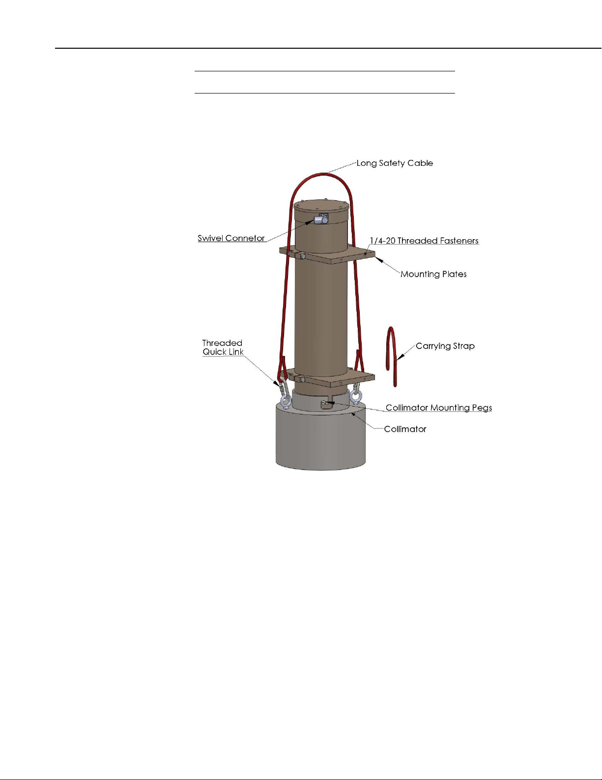
CS725 Snow Water Equivalency Sensor
CAUTION
The collimator weighs 25 kg (55 lb).
A long safety strap is also included for securing the collimator to the mounting
structure once it is installed.
FIGURE 7-1. CS725 components
8. Site Selection Details
It is important to determine if the intended installation site of the CS725 will
have appropriate sources of potassium and thallium to provide sufficient counts
for the expected SWE. It is also important to reduce the affects of background
sources that will adversely affect the SWE measurement.
Do not mount the CS725 in close proximity to wood material or trees. Wood
material can contain potassium (K) and thallium (TI) which can be a source of
gamma radiation that will interfere with the measurements. Potassium sources
above the snow will emit gamma radiation that is not attenuated by the snow
pack. Refer to the following sections for recommendations on how to select a
site.
18
Page 27

8.1 Collimator
CS725 Snow Water Equivalency Sensor
It is reasonable to have small amounts of wood material within the 6 m
clearance radius. Be aware that reducing the amount of material near the
CS725 or increasing the distance will reduce its influence on the readings.
The need for a collimator is typically dictated by the characteristics of the
intended site. The presence of wooded vegetation, man-made structures and
the expected SWE for a given site are all a factor.
It is possible to use the sensor and obtain accurate measurements without using
the collimator option. The following table is a guideline for determining if a
site can be used without a collimator.
TABLE 8-1. Collimator Guidelines
NOTE
Site Characteristics
Very open site with no
proximity to trees, buildings or
tall vegetation within a 48 m
(160 ft) radius.
No trees, buildings or tall
vegetation within a 24 m
(80 ft) radius.
No trees, buildings or tall
vegetation within a 12 m
(40 ft) radius.
Site with minimum clearance
radius of 6 m (20 ft) radius.
Always confirm that your sensor has the Collimator Installed
parameter set properly. The SWE calculations are different for a
sensor with and without a collimator.
Maximum
SWE
<300 mm
Optional Optional Optional
Optional Optional Required
Optional Required Required
Required Required Required
Maximum
SWE 300 to
400 mm
Maximum
SWE
>400 mm
8.2 Soil Moisture Considerations
Moisture in the soil can influence the CS725 readings. It is important to avoid
low lying spots were water will pool or saturate the soil during the snow melt.
Sandy or rocky soil types will have more stable soil moisture levels throughout
the measurement season. Bog type ground conditions should be avoided due to
the potentially high moisture content and variations.
8.3 Obtaining Site Qualifying Counts
There is variability in the natural occurring radiation levels from site to site.
For this reason, it is recommended to qualify the site prior to setting up the
permanent installation for the CS725. You may find that your site has low
19
Page 28

CS725 Snow Water Equivalency Sensor
background levels of K and Tl counts, and moving the location may be
required to improve the results from the CS725.
Required equipment:
• CS725 with accessories.
• Suitable +12 Vdc power supply or battery to run the CS725 for several
hours.
• Suitable mounting mechanism to suspend the CS725 vertically over the
ground at the qualifying site (with the collimator). For qualifying
purposes, the distance above the ground is not critical.
• Laptop computer with Hyperterminal or another suitable terminal emulator
program.
Steps to follow:
• Mount the CS725 as close as reasonable to its desired permanent location.
• Avoid placing items underneath the CS725 during this testing.
NOTE
• For best results try to maintain a mounting height of 1 m or more.
• Ensure that the collimator is installed on the CS725.
• Connect the CS725 to the laptop computer and power supply as shown in
Section 3, Wiring.
• Run Hyperterminal or the terminal program that you have chosen to use.
• Access the Parameter Setup menu by typing “.p<Enter>”.
• If not already done, change the operating state of the CS725 to Manual
mode. To do this type “19<space>1<Enter>”.
Once the site is qualified, the CS725 will need to have the
operating mode reconfigured to Auto or HCalib mode. This can
be done as part of the final parameter setup discussed in Section
10, Final Parameter Setup.
• The CS725 will automatically save this change and exit the Parameter
Setup menu.
• Enter into the “Special Command” by typing “.a<Enter>”
• The command will send out a prompt as follows:
Delay and Duration for the measurement (seconds)
(Delay should be greater than or equal to 5 s)
Format: =>Delay Duration
(example: => 5 3600)
20
Page 29

CS725 Snow Water Equivalency Sensor
• A delay will need to be typed in followed by the run time duration. It is
recommended to run the test for 1 or 2 hours; a value of 1 second can be
entered for the delay. A 1-hour test is 3600 seconds, so the following
would be typed in “1<space>3600<Enter>”.
• The CS725 will now monitor the gamma radiation for an hour.
• The .hr command can be issued several minutes into the test for
verification that it is running properly. The .hr command may take several
minutes to complete. Upon completion, the command will output the
current histogram (which can be captured to file for advanced diagnostics)
followed by the following lines.
-Elapsed time,current histo : 00:03:59
Pos K = 240.4; Pos Tl = 427.5;
Cnt K = 003679.8; Cnt Tl = 000088.3;
The first line indicates how long the CS725 has been monitoring. The
second line indicates the position of the potassium peak and its counts.
The third line indicates the position of the Tl peak and its counts.
It is important to record these numbers and refer to the radiation count
range in TABLE 8-2 and TABLE 8-3 for determining the suitability of
your site.
TABLE 8-2. Potassium (K) Count Range Guideline
Count Range
24 Hour K
Count Range
1 Hour K
Recommendation
0 to 96000 0 to 4000 Insufficient K counts for CS725
SWE measurements.
96000 to 180000 4000 to 7500 Useable K count range for CS725
SWE measurements. May
experience larger errors for higher
SWE values.
180000 to 264000 7500 to 11000 Good K count range for CS725
SWE measurements. Should
maintain specified operating
characteristics.
264000 or greater 11000 or greater Excellent K count range for the
CS725 SWE measurements.
21
Page 30

CS725 Snow Water Equivalency Sensor
TABLE 8-3. Thallium (Tl) Count Range Guideline
9. Mounting
CAUTION
Count Range
24 Hour Tl
0 to 9600 0 to 400 Insufficient Tl counts for CS725
9600 to 36000 400 to 1500 Useable Tl count range for CS725
36000 to 48000 1500 to 2000 Good Tl count range for CS725
48000 or greater 2000 or greater Excellent Tl count range for the
• If you are unable to determine that your structure or
mounting method is suitable for the CS725 sensor, please
contact an expert or professional who can assist you in
determining the structural mounting requirements for your
CS725 installation.
Count Range
1 Hour Tl
Recommendation
SWE measurements.
SWE measurements. May
experience larger errors for higher
SWE values.
SWE measurements. Should
maintain specified operating
characteristics.
CS725 SWE measurements.
• Always ensure that the collimator is secured to the
structure with the long safety cable.
• Always install the collimator after the main CS725 body is
mounted and secured to the structure.
The exact mounting height for the CS725 is not critical. However it is
recommended to mount the CS725 approximately 3.0 m (10 ft) above the
ground. If it is possible for snow levels to exceed 3.0 m (10 ft), then the CS725
should be mounted higher than the maximum snow height. If the CS725 is
submersed in the snow, it may be damaged by water ingress. The CS725 can
also be mounted lower than 3.0 m (10 ft); however, this will reduced the
effective area of coverage.
Once the CS725 is mounted, the actual installed height will need to be entered
into the appropriate setup parameter.
22
Page 31
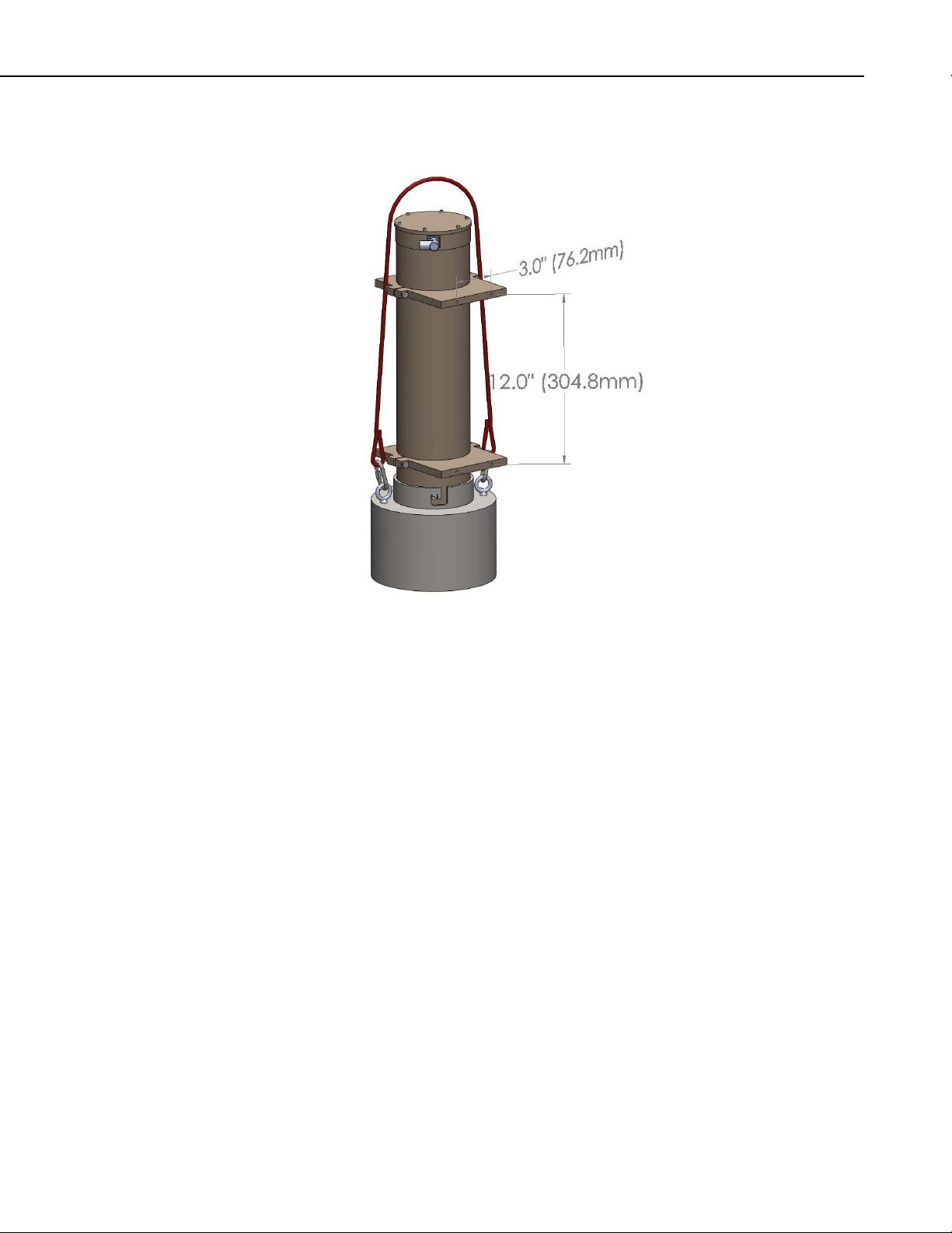
9.1 Mounting Options
CS725 Snow Water Equivalency Sensor
‐
FIGURE 9-1. Position of 1/4
The CS725 comes with mounting plates that can be used with the 27412
mounting kit and 27413 right-angle mounting kit to mount the sensor. The
mounting plates contain four ¼-20 threaded holes for fastening the sensor to
the 27413 or wall mount. Refer to FIGURE 9-1, Position of ¼-20 mounting
holes, for details.
20 mounting holes
23
Page 32

CS725 Snow Water Equivalency Sensor
FIGURE 9-2. Example of wall/plate mounting
It is possible to rotate the CS725’s main body with respect to the mounting
plates. FIGURE 9-2, Example of wall/plate mounting, shows one of four
fasteners that need to be loosened to rotate the main body. Ensure that the
fasteners are not loosened too much to prevent the body from sliding through
the mounting plates.
24
Page 33

CS725 Snow Water Equivalency Sensor
FIGURE 9-3. Horizontal pipe mounting shown with the 27412 Mount Kit
A fully mounted CS725 with the 27412 mounting brackets is shown in
FIGURE 9-3, Horizontal pipe mounting shown with the 27412 Mount Kit.
10. Final Parameter Setup
Once the CS725 is installed, the following items are required for the final setup
of the CS725.
• Obtain the soil moisture values for the ground under the CS725. The
recommended depth of the measurements for most soil types is 20 cm (8 in).
However, when well-drained soils are present, the measurements should
be made at a depth of 30 cm. The value should be in percent by weight
[100 *(mass of water/mass of dry soil)].
• Measure the final installed height of the CS725 in centimeters from the
bottom of the sensor to the ground.
It is best to have the CS725 installed prior to having any snow on the ground.
If the CS725 is being installed with snow already on the ground, then the
average existing SWE value in mm will need to be obtained. The existing
SWE is needed to calculate the background radiation count with no snow
present (i.e., n0Ke and n0Tl parameters). Campbell Scientific technical
support will need to be contacted so that calculations can be performed to
determine the n0K and n0Tl values.
25
Page 34

CS725 Snow Water Equivalency Sensor
If the installation is being done with no snow present, then the following needs
to be done to complete the setup:
Access the Parameter menu of the CS725 via the terminal emulator by keying
in the command [.p<Enter>]
[1] Station ID (Max 8 characters; ex: Gouin_21) : 001
[3] Time of start of measure (relative to GMON 00h RTC) : 00
[4] Delay after start of measure for data transmission (secs.)
0=> No transmission) : 0
[5] Frequency of data transmission: 0 => every 24 h
1 => every 6 h : 1
[6] GMON height above ground in centimeters : 300
[7] Observed position for the K line on the histogram : 245
[8] Collim (1: Collimator installed; 0: no collimator) : 1
[9] Nominal soil humidity in %weight,(min: 1, max: 150) : 25
[10] Estimated soil humidity in %weight (min: 1, max: 150)
for HCalib mode : 27
[11] NoK : 230000
[12] NooK (residual K counting) Default:0 : 225
[13] N0Tl : 41000
[14] n00Tl ( residual Tl counting) : 1900
[16] SN Threshold for the snow cover : 5
[17] Baud rate for scheduled transmissions : 9600
[18] Number of hours per partial histo (hours),(1,2,3,or 6) : 1
[19] Manual mode (1); Auto mode (0) ; HCalib mode (2); : 0
[0] Quit without saving the new parameters on EPROM
[99] Save parameters on EPROM
To modify: [parameter number, space, new value,CR]
=>
• Set parameter [6] to reflect the actual installed height of the CS725 in cm.
• Set parameter [9] to the obtained soil moisture value in %.
• Set parameter [10] to the obtained soil moisture value in %.
o If for any reason the soil moisture values cannot be obtained, then
an estimate could be made based on the soil type as follows:
Sandy soil – 15%
Sand/Organic mixture – 30%
Humus soil – 50%
• Ensure any other parameter is set to meet your requirements.
• Set parameter [19] last. Set the value to 2 - “Calibration Mode”. The
CS725 will automatically reset when this parameter is changed and saved.
• Always key in the [99] command to save the parameters. The CS725 will
prompt the user a second time for the 99 command to avoid an inadvertent
save.
• The setting can be verified by going back into the [.p] Parameter menu
again.
By placing the CS725 in calibration mode (HCalib), it will automatically adjust
the initial n0K and the n0Tl values for you. The n0K and the n0Tl values can
also be calculated by running the CS725 for 24 hours and observing the
26
Page 35

CS725 Snow Water Equivalency Sensor
radiation count values seen in the detailed measurement data output string
which can be accessed by typing the command [.fl].
11. Firmware Update (using command .0xw)
The firmware for the CS725 can be updated using the RS-232 serial
communication interface. This can be accomplished by connecting the CS725
to a computer using the DB9F-TERM (see Section 4, Connecting the CS725 to
a Computer).
A terminal communication program such as Hyperterminal will be required to
transfer the new firmware file to the CS725.
The firmware update involves the transfer of a large file, and for this reason the
baud rate setting can be increased for the program update procedure. The
maximum baud rate that can be used is a function of the cable length. The
following table shows the recommended maximum baud rate for various cable
lengths:
Cable Length Maximum Baud Rate
0 to 7.6 m (0 to 25 ft) 57600
0 to 15.2 m (25 to 50 ft) 38400
0 to 30.5 m (50 to 100 ft) 9600
Terminal settings should be as follows:
Baud Rate: See table above
Data Bits: 8
Parity: None
Stop Bits: 1
Flow Control: XON/XOFF
Local Echo: Enabled
Terminal Mode: ANSI
Send Line Ends with Line Feeds: Disabled
Note that the XON/XOFF flow control needs to be enabled. For all other
normal communications, the XON/XOFF flow control will need to be disabled.
Once the terminal program is setup and the CS725 is connected to the
computer using the DB9F-Term, power can be applied to the CS725.
If a baud rate other than 9600 was selected, the auto baud rate synchronization
can be invoked by typing the command “UU.<Enter>”. Once the menu is
displayed, the command “.0xw” can be entered for reprogramming the
firmware.
The following will be displayed once the “.0xw” is entered:
allocating memory buffer,,,,,,,,,,,
27
Page 36

CS725 Snow Water Equivalency Sensor
After the memory is allocated (within 1 minute), the CS725 will prompt for the
file transfer with the following message:
Launch the file transfer with the Hyper Terminal
If you are using HyperTerminal, select “Send Text File…” from the Transfer
menu.
The supplied programming file will need to be selected and sent to the CS725.
The process will take approximately 5 minutes at 57600 bps and in excess of
30 minutes at 9600 bps. If the scrolling characters stop for a long duration, it is
possible that an error occurred in communications. Shut down Hyperterminal,
power down the CS725, and restart the process again.
A single line of scrolling data will be displayed as the transfer takes place.
Once the transfer is complete, the following text will be displayed on the
terminal:
Transfer completed; type w to overwrite the EPROM memory, type . to
abort
CAUTION
Once the following step is done, it is critical to not
interrupt this process or power down the CS725. If
the process is interrupted, the CS725 may need to
be sent back to the factory for reprogramming.
Type in the character w followed by the enter key “w<Enter>”.
After the w command is entered, the terminal will display that the
programming has begun and the progress will be displayed as follows:
Begin EPROM programming
Erasing block 0x0
Writing EPROM from 0x0 to 0xffff
Upon completion the CS725 will prompt to be reset. It is recommended to
cycle power only after the following message is displayed:
Programming done .. cycle power on the GMONIII, or do a Hard Reset
It is recommended to restart Hyperterminal as well and change the baud rate
setting back to 9600 bps and to disable the XON/XOFF flow control to resume
normal communications and verify that the CS725 powers up properly and
retained its parameter settings.
28
Page 37

CS725 Snow Water Equivalency Sensor
12. System Power Requirements and Recommendations
12.1 Non Solar-Powered Sites
It is always recommended that the CS725 be operated from an uninterruptable
power supply. Normally an AC charger is used to charge +12 Vdc batteries.
For sites that operate this way, it is recommended that the batteries have the
capacity to supply the system for a minimum of 48 hours. This should be
increased for sites where frequent power outages are possible.
12.2 Solar-Powered Sites
The maximum power draw from the CS725 is 180 mA or 4.32 Ah per day. It
is recommended that solar-powered systems be designed with a minimum
reserve capacity of 60 days. This results in a minimum reserve capacity of 260
Ah for the CS725. It is also important to account for the power draw from
other equipment that may operate from the power supply.
The following are some reasons for the large reserve capacity.
• Solar panels can become covered in ice and snow and charging may not be
present for long periods of time.
• Battery capacity decreases with cold temperatures.
• Cold temperatures also significantly reduce a battery’s capacity to charge.
Generally very little charging occurs at temperatures below -30°C.
Solar Panel Size
The size of solar panel required for charging the CS725 system should be sized
according to the geographic location of the installation and total maximum
system power draw.
13. Detailed Measurement Theory
The CS725 sensor is, in fact, a gamma radiation spectrometer that has been
specifically designed for the purpose of measuring SWE. The CS725 uses a
thallium doped sodium iodide crystal NaI(Tl) for detecting the gamma
radiation.
The natural gamma radiation from the ground is produced by the traces of
long-lived radioactive elements that it contains. The most abundant of those
elements is Potassium_40 (
gammas at 1.460 MeV (megaelectronvolts), and Thallium_208 at 2.613 MeV.
Gamma rays have a well defined “probability of interaction” per unit of length
as they go through a material according to the energy of the gamma and the
nature of the material. The net effect when the natural gamma rays from the
ground go through the snow cover is that a fraction of the gammas do not
interact at all with the snow, and that another fraction is either degraded in
energy, or totally absorbed in the snow. The precise measurement of the
40
K) and Thallium_208 (
208
Tl). Potassium_40 emits
29
Page 38
CS725 Snow Water Equivalency Sensor
absorption and energy degradation by the snow of the gamma rays from the
ground is the basic information for the calculation of the SWE.
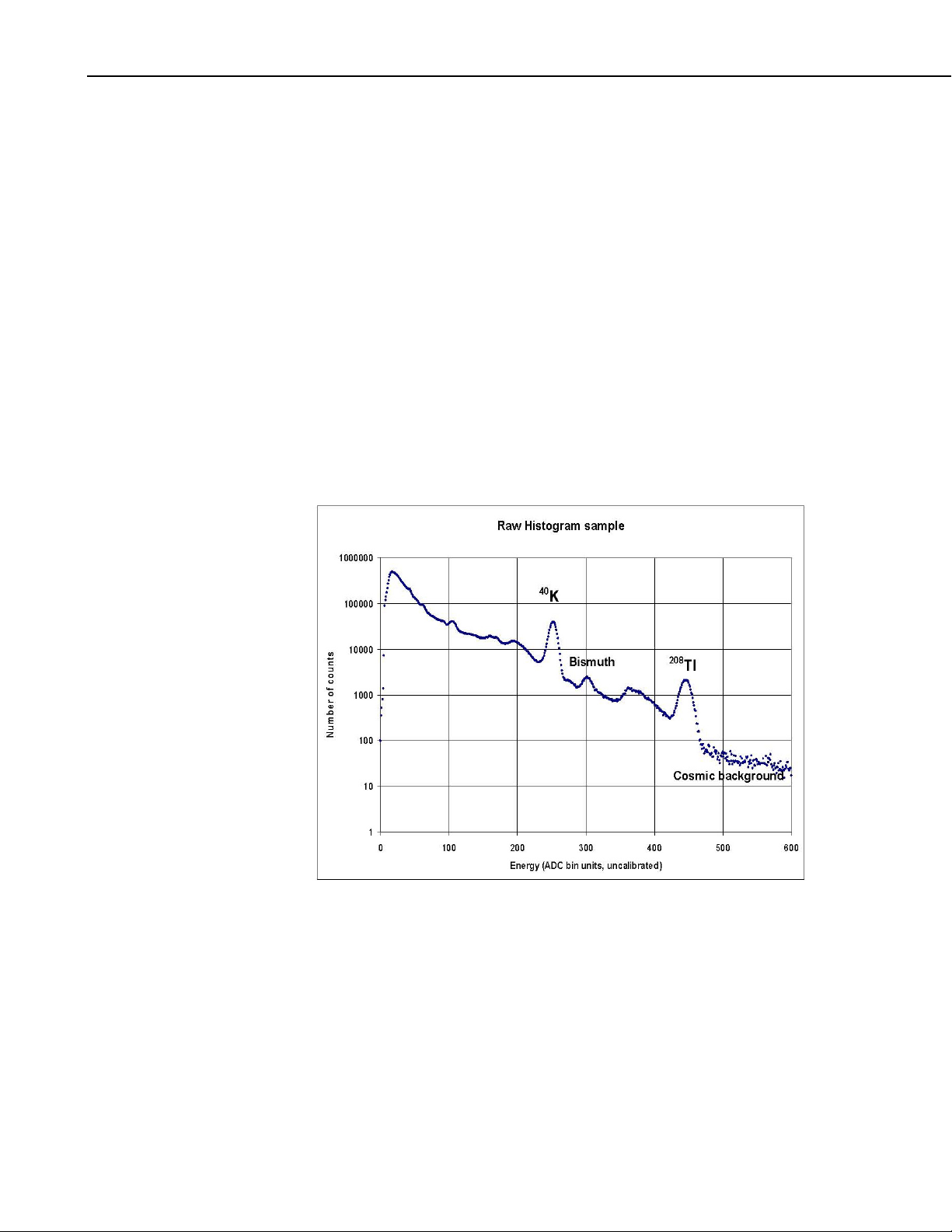
Each time a gamma ray is detected by the CS725, it is placed in its
corresponding bin in the energy histogram. This histogram is the basic data set
for the calculation of the SWEs. Since it is statistical in nature, the accuracy of
the SWE evaluation is proportional to the square root of the measurement time.
The CS725 builds each histogram for a period of 24 hours in order to achieve
the specified accuracy. An example of such a histogram is shown in FIGURE
13-1, Gamma histogram.
It should be noted that only selected portions of the histogram can be used to
evaluate the SWE. The reason is that the SWE is evaluated by measuring the
absorption by the snow cover of the natural radiation coming from the ground.
However, some of the measured radiation comes from above the snow cover.
This is the case of the cosmic radiation and the bismuth isotopes produced by
the radon decay chain. In short, the integrated counts under the
peaks need to be evaluated after removing or accounting for all the other
contaminants.
40
K and
208
Tl
30
FIGURE 13-1. Gamma histogram
Page 39

14. Maintenance and Assembly
There is no recommended user maintenance required for the CS725.
CS725 Snow Water Equivalency Sensor
CAUTION
We do not recommend disassembling the CS725 for any
reason. The CS725 instrument is very complex and is
intended to be repaired or maintained only by factory
trained personnel.
It is recommended that the CS725 be calibrated every seven years. The reason
for the timeline is to ensure the CS725 gamma ray detector does not drift out of
specification.
The following diagrams demonstrate the internal makeup of the CS725. To
reduce drastic temperature gradients, the CS725 is filled with an advanced
insulating material known as Nanogel (see FIGURE 14-3, CS725 cutout view).
The manufacturer’s (Cabot Corporation) MSDS sheet should be consulted
prior to exposing the Nanogel insulation.
FIGURE 14-1. CS725 main body
31
Page 40

CS725 Snow Water Equivalency Sensor
FIGURE 14-2. CS725 inner tube shown
32
FIGURE 14-3. CS725 cutout view
Page 41

CS725 Snow Water Equivalency Sensor
FIGURE 14-4. CS725 with top cap removed
15. Datalogger CRBasic Programming
15.1 Extended Data Output (.flla) Command
The following program example reads the data values from the CS725 using
the command [.flla].
This program obtains information in addition to reported SWE values such as
radiation counts and other diagnostic information.
'CR1000 Series Datalogger
'Program for CS725 Sensor
'Wiring CS725
'Red - +12VDC
'Black and Clear- G - Ground
'Green RS-232 TX - C2
'White RS-232 RX - C1
'Clear Shield- G – Ground
'Declare Public Variables and alias
Public PTemp As Float,batt_volt As Float
Public Read_CS725_SWE_Flag As Boolean
Public CS725SerialIn As String * 120
Public CS725_COMMAND_String As String * 20
Public CS725_TIME_String As String * 17
Public CS725_Date_Time(5) As Float
33
Page 42

CS725 Snow Water Equivalency Sensor
Alias CS725_Date_Time(1) = CS725_Day
Alias CS725_Date_Time(2) = CS725_Month
Alias CS725_Date_Time(3) = CS725_Year
Alias CS725_Date_Time(4) = CS725_Hour
Alias CS725_Date_Time(5) = CS725_Min
Public CS725_StationID As String * 10
Public CS725_Values(17) As Float
Alias CS725_Values(1) = CS725_SerialNum
Alias CS725_Values(2) = CS725_K_Uncorrected
Alias CS725_Values(3) = CS725_K_Counts
Alias CS725_Values(4) = CS725_TL_Counts
Alias CS725_Values(5) = CS725_SWE_K
Alias CS725_Values(6) = CS725_K_TL_Ratio
Alias CS725_Values(7) = CS725_SWE_TL
Alias CS725_Values(8) = CS725_SM_K
Alias CS725_Values(9) = CS725_SM_TL
Alias CS725_Values(10) = CS725_SM_K_TL
Alias CS725_Values(11) = CS725_Precip_Index
Alias CS725_Values(12) = CS725_Crystal_TEMP_MIN
Alias CS725_Values(13) = CS725_Crystal_TEMP_MAX
Alias CS725_Values(14) = CS725_Hist_Blocks
Alias CS725_Values(15) = CS725_K_Disp
Alias CS725_Values(16) = CS725_Stats
Alias CS725_Values(17) = CS725_PWR_Volt
Public CS725SplitStr(20) As String * 16
Dim loopcount As Long
'Declare Constants
'Command to Read back last results in short data output form
'preceed .flla with an ESCAPE key CHR(27) and emd with an Enter CHR(13)
Const CS725_Command_get_output = CHR(27) + ".flla" + CHR(13)
'Define Data Tables
DataTable (Diagnostics,1,-1)
DataInterval (0,1440,Min,10)
Minimum (1,batt_volt,FP2,0,False)
Maximum (1,batt_volt,FP2,0,False)
Minimum (1,PTemp,FP2,0,False)
Maximum (1,PTemp,FP2,0,False)
EndTable
'Define Data Tables
DataTable (CS725_6Hour,1,-1)
DataInterval (30,360,Min,10)
Sample (1,CS725_TIME_String,String)
Sample (1,CS725_StationID,String)
Sample (1,CS725_SerialNum,IEEE4)
Sample (1,CS725_K_Counts,IEEE4)
Sample (1,CS725_TL_Counts,IEEE4)
Sample (1,CS725_SWE_K,IEEE4)
Sample (1,CS725_K_TL_Ratio,IEEE4)
Sample (1,CS725_SWE_TL,IEEE4)
Sample (1,CS725_Crystal_TEMP_MIN,IEEE4)
Sample (1,CS725_Crystal_TEMP_MAX,IEEE4)
Sample (1,CS725_Hist_Blocks,IEEE4)
Sample (1,CS725_K_Disp,IEEE4)
Sample (1,CS725_PWR_Volt,IEEE4)
EndTable
34
Page 43

CS725 Snow Water Equivalency Sensor
'Main Program
BeginProg
'Prepare COM1 for the CS725
SerialOpen (Com1,9600,3,0,1000)
'Scan rate is dependent on application
Scan (30,Sec,7,0)
PanelTemp (PTemp,250)
Battery (batt_volt)
'Based on the Factory default settings of the CS725 will
'calculate SWE on the Hour every 6 Hours.
'The CS725 is read every 6 hour in this program.
'The reading will take place 10 minutes After the period to ensure the CS725 is not
'processing calculations at the top of the hour when the measurement is requested
'flag is set 10 minutes into every 6 hour period
If TimeIntoInterval (10,360,Min) Then Read_CS725_SWE_Flag = TRUE
'If the flag is high obtain a measurement
If Read_CS725_SWE_Flag = TRUE Then
'Reset the Flag
Read_CS725_SWE_Flag = False
'Load the command into the string
CS725_COMMAND_String = CS725_Command_get_output
'Flush the serial buffer
SerialFlush (Com1)
'Send the command string out
SerialOut (Com1,CS725_COMMAND_String,"",0,0)
'Wait up to 2 seconds, a <CR> or 100 chars for the values to be returned.
SerialIn (CS725SerialIn, Com1, 200,13, 100)
'The string is in the following format
'08/11/2010 11:59: 1234 23 637733 485431 24425 80 76 79 22 23 21 0 6 12 24 -1 1.3 12.05
'Split out the string into smaller strings - use a space as the filter
SplitStr (CS725SplitStr(1),CS725SerialIn," ",20,5)
'first string contains 08/11/2010
SplitStr (CS725_Date_Time(1),CS725SplitStr(1),"",3,0)
'Next string contains HH:MM
SplitStr (CS725_Date_Time(4),CS725SplitStr(2),"",2,0)
'Next string contains the station identifier and is left as a string
CS725_StationID = CS725SplitStr(3)
'The next 17 strings are all numerical values
For loopcount = 1 To 17 Step 1
'Convert all strings to numbers
'Values produced are as follows"
'CS725_SerialNum *Suggest to Output to Final Storage*
'CS725_K_Uncorrected
'CS725_K_Counts *Suggest to Output to Final Storage*
'CS725_TL_Counts *Suggest to Output to Final Storage*
'CS725_SWE_K *Suggest to Output to Final Storage*
'CS725_K_TL_Ratio *Suggest to Output to Final Storage*
'CS725_SWE_TL *Suggest to Output to Final Storage*
'CS725_SM_K
'CS725_SM_TL
'CS725_SM_K_TL
'CS725_Precip_Index
'CS725_Crystal_TEMP_MIN *Suggest to Output to Final Storage*
35
Page 44

CS725 Snow Water Equivalency Sensor
'CS725_Crystal_TEMP_MAX *Suggest to Output to Final Storage*
'CS725_Hist_Blocks *Suggest to Output to Final Storage*
'CS725_K_Disp *Suggest to Output to Final Storage*
'CS725_Stats
'CS725_PWR_Volt *Suggest to Output to Final Storage*
SplitStr (CS725_Values(loopcount),CS725SplitStr(loopcount + 3),"",1,0)
Next
'Prepare the output time string from when the CS725 produced the data
'Format is YYYY-MM-DD HH:MM
CS725_TIME_String = FormatFloat (CS725_Year,"%04.0f") + "-" + FormatFloat
(CS725_Month,"%02.0f") + "-" + FormatFloat (CS725_Day,"%02.0f") + " " + FormatFloat
(CS725_Hour,"%02.0f") + ":" + FormatFloat (CS725_Min,"%02.0f")
EndIf
'Call Output Tables.
CallTable Diagnostics
CallTable CS725_6Hour
NextScan
EndProg
15.2 Short Form Data Output (.fs) Command
The following program example reads the SWE values from the CS725 using
the command [.fs].
The format of the data output from [.fs] command is as follows:
DD/MM/YYYY HH:MM:SS SWE_K SWE_TL
01/10/2009 06:59:50 123 129
'CR1000 Series Datalogger
'Program for CS725 Sensor
'Wiring CS725
'Red -Power +12VDC
'Black -Power Gnd G - Ground
'Green -RS-232 TX C2
'White -RS-232 RX C1
'Clear -Shield G – Ground
'Declare Public Variables
Public PTemp As Float,batt_volt As Float
Public Read_CS725_SWE_Flag As Boolean
Public CS725_RET_Values(8) As Float
Public CS725SerialIn As String * 100
Public CS725_COMMAND_String As String * 20
Alias CS725_RET_Values(7) = SWE_K
Alias CS725_RET_Values(8) = SWE_TL
'Declare Constants
'Command to Read back last results in short data output form
'precede .Fs with an ESCAPE key CHR(27) and emd with an Enter CHR(13)
Const CS725_Command_get_output = CHR(27) + ".Fs" + CHR(13)
36
Page 45

CS725 Snow Water Equivalency Sensor
'Define Data Tables
DataTable (Diagnostics,1,-1)
DataInterval (0,1440,Min,10)
Minimum (1,batt_volt,FP2,0,False)
Maximum (1,batt_volt,FP2,0,False)
Minimum (1,PTemp,FP2,0,False)
Maximum (1,PTemp,FP2,0,False)
EndTable
'Define Data Tables
DataTable (CS725Hourly,1,-1)
DataInterval (0,60,Min,10)
Sample (8,CS725_RET_Values(1),IEEE4)
EndTable
'Main Program
BeginProg
'Prepare COM1 for the CS725
SerialOpen (Com1,9600,3,0,10000)
'Scan rate is dependent on application
Scan (30,Sec,7,0)
PanelTemp (PTemp,250)
Battery (batt_volt)
'Based on the Factory default settings of the CS725 the CS725 will
'calculate SWE on the Hour every 6 Hours.
'We will simply read the CS725 every hour in this program.
'The reading will take place 10 minutes After the hour to ensure the CS725
'is not burdened with extra processing when the measurement is requested
If TimeIntoInterval (10,60,Min) Then Read_CS725_SWE_Flag = TRUE
EndIf
If Read_CS725_SWE_Flag = TRUE Then
'Reset the Flag
Read_CS725_SWE_Flag = False
'Load the command into the string
CS725_COMMAND_String = CS725_Command_get_output
'Send the command string out
SerialOut (Com1,CS725_COMMAND_String,"",0,0)
'Wait up to 2 seconds, a <CR> or 100 chars for the values to be returned.
SerialIn (CS725SerialIn, Com1, 200,13, 100)
'The string is in the following format
'23/09/2009 18:59:50 123 456
'Split out the time stamp and values 8 numbers are returned
SplitStr (CS725_RET_Values(),CS725SerialIn,"",8,0)
'The contents of the array are as follows:
'Day,Month,Year,Hour,Min,Second,SWE-from K, SWE-from TL
EndIf
'Call Output Tables.
CallTable Diagnostics
CallTable CS725Hourly
NextScan
EndProg
37
Page 46

CS725 Snow Water Equivalency Sensor
38
Page 47

Page 48

Campbell Scientific Companies
Campbell Scientific, Inc. (CSI)
815 West 1800 North
Logan, Utah 84321
UNITED STATES
www.campbellsci.com
Campbell Scientific Africa Pty. Ltd. (CSAf)
Somerset West 7129
SOUTH AFRICA
www.csafrica.co.za
Campbell Scientific Australia Pty. Ltd. (CSA)
Garbutt Post Shop QLD 4814
www.campbellsci.com.au
Campbell Scientific do Brazil Ltda. (CSB)
Rua Luisa Crapsi Orsi, 15 Butantã
CEP: 005543-000 São Paulo SP BRAZIL
www.campbellsci.com.br
Campbell Scientific Canada Corp. (CSC)
11564 - 149th Street NW
Edmonton, Alberta T5M 1W7
www.campbellsci.ca
Campbell Scientific Centro Caribe S.A. (CSCC)
300 N Cementerio, Edificio Breller
Santo Domingo, Heredia 40305
www.campbellsci.cc
Campbell Scientific Ltd. (CSL)
Shepshed, Loughborough LE12 9GX
UNITED KINGDOM
www.campbellsci.co.uk
Campbell Scientific Ltd. (France)
3 Avenue de la Division Leclerc
www.campbellsci.fr
Campbell Scientific Spain, S. L.
Avda. Pompeu Fabra 7-9, local 1
www.campbellsci.es
Please visit www.campbellsci.com to obtain contact information for your local US or interna tional representative.
• info@campbellsci.com
PO Box 2450
• cleroux@csafrica.co.za
PO Box 8108
AUSTRALIA
• info@campbellsci.com.au
• suporte@campbellsci.com.br
CANADA
• dataloggers@campbellsci.ca
COSTA RICA
• info@campbellsci.cc
Campbell Park
80 Hathern Road
• sales@campbellsci.co.uk
92160 ANTONY
FRANCE
• info@campbellsci.fr
08024 Barcelona
SPAIN
• info@campbellsci.es
 Loading...