

Page 1

INSTRUCTION MANUAL
CS500 Temperature and
Relative Humidity Probe
Revision: 7/04
Copyright (c) 1995-2004
Campbell Scientific, Inc.
Page 2

Warranty and Assistance
The CS500 TEMPERATURE AND RELATIVE HUMIDITY PROBE is
warranted by CAMPBELL SCIENTIFIC, INC. to be free from defects in
materials and workmanship under normal use and service for twelve (12)
months from date of shipment unless specified otherwise. Batteries have no
warranty. CAMPBELL SCIENTIFIC, INC.'s obligation under this warranty is
limited to repairing or replacing (at CAMPBELL SCIENTIFIC, INC.'s option)
defective products. The customer shall assume all costs of removing,
reinstalling, and shipping defective products to CAMPBELL SCIENTIFIC,
INC. CAMPBELL SCIENTIFIC, INC. will return such products by surface
carrier prepaid. This warranty shall not apply to any CAMPBELL
SCIENTIFIC, INC. products which have been subjected to modification,
misuse, neglect, accidents of nature, or shipping damage. This warranty is in
lieu of all other warranties, expressed or implied, including warranties of
merchantability or fitness for a particular purpose. CAMPBELL SCIENTIFIC,
INC. is not liable for special, indirect, incidental, or consequential damages.
Products may not be returned without prior authorization. The following
contact information is for US and International customers residing in countries
served by Campbell Scientific, Inc. directly. Affiliate companies handle repairs
for customers withi n their territories. Please visit www.campbe llsci.com to
determine which Campbell Scientific company serves your country. To obtain
a Returned Materials Authorization (RMA), contact CAMPBELL
SCIENTIFIC, INC., phone (435) 753-2342. After an applications engineer
determines the nature of the problem, an RMA number will be issued. Please
write this number clearly on the outside of the shipping container.
CAMPBELL SCIENTIFIC's shipping address is:
CAMPBELL SCIENTIFIC, INC.
RMA#_____
815 West 1800 North
Logan, Utah 84321-1784
CAMPBELL SCIENTIFIC, INC. does not accept collect calls.
Page 3

CS500 Table of Contents
PDF viewers note: These page numbers refer to the printed version of this document. Use
the Adobe Acrobat® bookmarks tab for links to specific sections.
1. General........................................................................1
2. Specifications .............................................................1
2.1 Temperature Sensor..................................................................................1
2.2 Relative Humidity Sensor.........................................................................2
3. Installation...................................................................2
4. Wiring ..........................................................................6
5. Example Programs .....................................................6
5.1 Example for CR1000................................................................................7
5.2 Example for CR10X.................................................................................7
6. Long Lead Lengths.....................................................8
7. Absolute Humidity......................................................9
8. Maintenance..............................................................11
9. References ................................................................11
Figures
1. CS500 and 41301 Radiation Shield on a CM6/CM10 Tripod Mast...........3
2. CS500 and 41303 Radiation Shield............................................................4
3. CS500 and 41003 Radiation Shield on a CM6/CM10 Tripod Mast...........4
4. Radiation Shield, CS500, and 41381 Adapter ............................................5
5. CS500 Wiring.............................................................................................5
Tables
1. Datalogger Connections..............................................................................6
2. Calibration for Temperature.......................................................................6
3. Calibration for Relative Humidity...............................................................6
4. Wiring for CR1000 and CR10X Examples................................................. 7
5. CR10(X) Wiring for Example 1..................................................................9
i
Page 4

This is a blank page.
Page 5

CS500 Temperature and Relative Humidity Probe
1. General
The CS500 Temperature and Relative Humidity probe contains a Platinum
Resistance Temperature detector (PRT) and a Vaisala INTERCAP® capacitive
relative humidity sensor.
The -L option on the model CS500 Temperature and Relative Humidity probe
(CS500-L) indicates that the cable length is user specified. This manual refers
to the sensor as the CS500.
2. Specifications
Operating Temperature: -40°C to +60°C
Storage Temperature: -40°C to +80°C
Probe Length: 6.8 cm (2.66 in.)
Probe Body Diameter: 1.2 cm (0.47 in.)
Filter: 0.2 µm Teflon membran e
Filter Diameter: 1.2 cm (0.47 in.)
Housing Material: ABS Plastic
Power Consumption: < 2 mA
Supply Voltage: 7 to 28 VDC
Settling Time after power is switched on: 1 second
2.1 Temperature Sensor
Sensor: 1000 Ω PRT, DIN 43760B
Temperature Measurement Range: -40°C to +60°C
Temperature Output Signal range : 0 to 1.0 VDC
1
Page 6
CS500 Temperature and Relative Humidity Probe
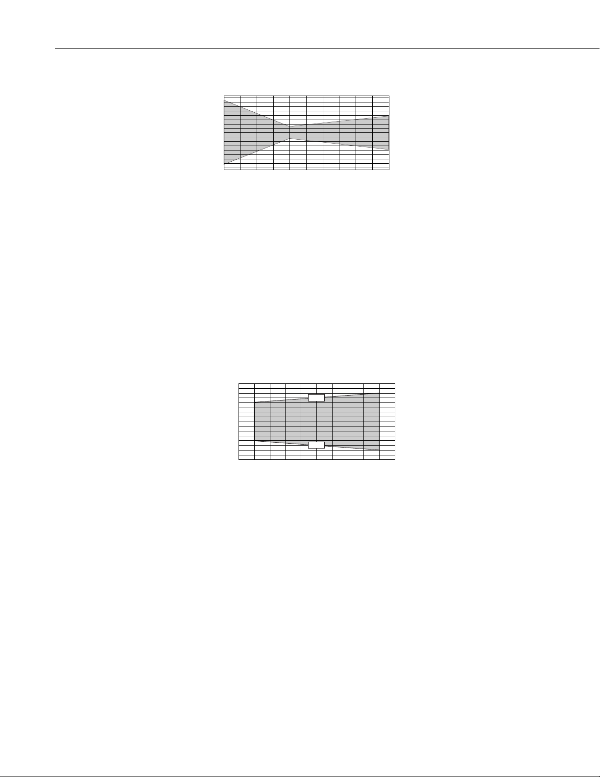
Temperature Accuracy:
1.6
1.2
0.8
0.4
o
( C)
0
-0.4
Error
-0.8
-1.2
-1.6
-20-40 0
2.2 Relative Humidity Sensor
Sensor: INTERCAP
Relative Humidity Measurement Range: 0 to 100% non-condensing
RH Output Signal Range: 0 to 1.0 VDC
Accuracy at 20°C
unspecified (0 to 10% Relative Humidity)
±3% RH (10 to 90% Relative Humidity)
±6% RH (90 to 100% Relative Humidity)
20 40 60
Temperature( C)
®
o
3. Installation
Temperature Dependence of Relative Humidity Measurement:
1.5
1.0
o
0.5
C
0
-0.5
( %RH/ )
-1.0
-1.5
Temperature Dependence
10 20 30 40 50 60 70 80 90 100
60 C
-40 C
RH (%)
o
o
Typical Long Term Stability: Better than 1% RH per year
Response Time (at 20°C, 90% response to a steep change in humidity):
15 seconds with membrane filter
The CS500 must be housed inside a solar radiation shield when used in the
field. The 41303 6-Plate Radiation Shield (Figure 1) mounts to a CM6/CM10
tripod or UT10 tower. The CS500 is held within the 41301 by a mounting
clamp (Figure 2).
The 41003 10-Plate Radiation Shield (Figure 3) mounts to a CM6/CM10
tripod. The UT12VA 12-Plate Radiation Shield mounts to a UT10 or UT30
tower with the UT018 horizontal mounting arm.
2
Page 7

NOTE
CS500 Temperature and Relative Humidity Probe
The CS500 is held in place, within the 41003 or UT12VA Radiation Shield, via
an adapter, Model 41381. The 41381 adapter is threaded onto the bottom of
the CS500 (Figure 4). The 41004 12-Plate Radiation Shield, used with 207
probes, can be converted to a 41002 with P/N 6638.
®
The black outer jacket of the cable is Santoprene
rubber. This
compound was chosen for its resistance to temperature extremes,
moisture, and UV degradation. However, this jacket will support
combustion in air. It is rated as slow burning when tested
according to U.L. 94 H.B. and will pass FMVSS302. Local fire
codes may preclude its use inside buildings.
FIGURE 1. CS500 and 41301 Radiation Shield
on a CM6/CM10 Tripod Mast
3
Page 8

CS500 Temperature and Relative Humidity Probe
Mounting Clamp
FIGURE 2. CS500 and 41303 Radiation Shield
FIGURE 3. CS500 and 41003 Radiation Shield
on a CM6/CM10 Tripod Mast
4
Page 9

CS500 Temperature and Relative Humidity Probe
Tripod Mast
41003 10-Plate Radiation Shield
Lock nut tightens against adapter
CS500
Internal threads secure the CS500 to adapter
41381 Adapter
FIGURE 4. Radiation Shield, CS500, and 41381 Adapter
Black Temperature Signal
Brown Relative Humidity Signal
Green Signal & Power Reference
Red Power
Clear Shield
FIGURE 5. CS500 Wiring
5
Page 10

CS500 Temperature and Relative Humidity Probe
TABLE 1. Datalogger Connections
Description Color CR23X/CR1000 CR10(X), CR510 21X, CR7
Temperature Black Single-Ended Input Single-Ended Input Single-Ended Input
Relative Humidity Brown Single-Ended Input Single-Ended Input Single-Ended Input
Signal & Power
Reference
Power Red 12 V 12 V 12 V
Shield Clear G
Green G G
4. Wiring
Connections to Campbell Scientific dataloggers are given in Table 1. The
probe is measured by two single-ended analog input channels, one for
temperature and one for relative humidity.
CAUTION
Always connect the Green lead to the datalogger first,
followed by the Black, Brown, and Clear leads. Connect
the Red (Power) lead last.
5. Example Programs
This section is for users who write their own datalogger programs. A
datalogger program to measure this sensor can be created using Campbell
Scientific’s Short Cut Program Builder Software. You do not need to read this
section to use Short Cut.
The temperature and relative humidity signals from the CS500 are measured
using two single-ended analog measurements (Instruction 1).
The probe output scale is 0 to 1000 millivolts for the temperature range of 40°C to +60°C and for the relative humidity range of 0 to 100%. Tables 2 and
3 provide calibration information for temperature and relative humidity.
TABLE 2. Calibration for Temperature
Units Multiplier
Celsius 0.1 -40
Fahrenheit 0.18 -40
(degrees mV-1)
Offset
(degrees)
TABLE 3. Calibration for Relative Humidity
Units Multiplier
(% mV-1)
Percent 0.1 0
Fraction 0.001 0
6
Offset
(%)
Page 11

TABLE 4. Wiring for CR1000 and CR10X Examples
Description Color CR1000 CR10(X)
Temperature Black SE 1 SE 3 (2H)
Relative Humidity Brown SE 2 SE 4 (2L)
Signal & Power Refer ence Green G G
Power Red 12 V 12 V
Shield Clear G
5.1 Example for CR1000
'CR1000
'Created by SCWIN (2.1)
Public AirTC
Public RH
DataTable(Table1,True,-1)
DataInterval(0,60,Min,0)
Average(1,AirTC,IEEE4,0)
Sample(1,RH,IEEE4)
EndTable
CS500 Temperature and Relative Humidity Probe
BeginProg
Scan(5,Sec,1,0)
'CS500 Temperature & Relative Humidity Sensor measurements AirTC and RH:
VoltSE(AirTC,1,mV2500,1,0,0,_60Hz,0.1,-40.0)
VoltSE(RH,1,mV2500,2,0,0,_60Hz,0.1,0)
If (RH>100) And (RH<108) Then RH=100
CallTable(Table1)
NextScan
EndProg
5.2 Example for CR10X
;Measure the CS500 temperature.
;
01: Volt (SE) (P1)
1: 1 Reps
2: 5 2500 mV Slow Range ;CR500 (2500 mV); CR23X (1000 mV); 21X,
CR7 (5000 mV)
3: 3 SE Channel ;Black wire (SE 3), Green wire (G)
4: 1 Loc [ T_C ]
5: .1 Mult ;See Table 2 for alternate multipliers
6: -40 Offset ;See Table 2 for alternate offsets
7
Page 12

CS500 Temperature and Relative Humidity Probe
;Measure the CS500 relative humidity.
;
02: Volt (SE) (P1)
1: 1 Reps
2: 5 2500 mV Slow Range ;CR500 (2500 mV); CR23X (1000 mV); 21X,
3: 4 SE Channel ;Brown wire (SE 4), Green wire (G)
4: 3 Loc [ RH_pct ]
5: .1 Mult ;See Table 3 for alternate multipliers
6: 0 Offset
;Limit the maximum relative humidity to 100%.
;
03: If (X<=>F) (P89)
1: 3 X Loc [ RH_pct ]
2: 3 >=
3: 100 F
4: 30 Then Do
04: Z=F (P30)
1: 100 F
2: 0 Exponent of 10
3: 3 Z Loc [ RH_pct ]
CR7 (5000 mV)
05: End (P95)
6. Long Lead Lengths
Long lead lengths cause errors in the measured temperature and relative
humidity. The approximate error in temperature and relative humidity is
0.35°C and 0.35% per 100 feet of cable length, respectively.
When long lead lengths are required and the above errors in temperature and
relative humidity are unacceptable, use the HMP45C temperature and humidity
probe.
Understanding the following details are not required for the general operation
of the CS500 with Campbell Scientific’s dataloggers. The signal reference and
the power ground (black) are the same lead in the CS500. When the CS500
temperature and relative humidity are measured, both the signal reference and
power ground are connected to ground at the datalogger. The signal
reference/power ground lead serves as the return path for 12 V. There will be a
voltage drop along this lead because the wire itself has resistance. The CS500
draws approximately 2 mA when it is powered. The wire used in the CS500
(P/N 9720) has resistance of 17.5 Ω/1000 feet. Using Ohm’s law, the voltage
drop (V
), along the signal reference/ power ground lead, is given by Eq. (1).
d
V
IR
d =∗
=∗
mA ft
2 175 1000
=
mV ft
35 1000
8
. Ω
(1)
Page 13

This voltage drop will raise the apparent temperature and relative humidity
because the difference between the signal and signal reference, at the
datalogger, has increased by V
relative humidity is 0.35
respectively.
7. Absolute Humidity
The CS500 measures the relative humidity. Relative humidity is defined by the
equation below:
CS500 Temperature and Relative Humidity Probe
. The approximate error in temperature and
d
°C and 0.35% per 100 feet of cable length,
e
RH
100
=∗ (2)
e
s
where RH is the relative humidity, e is the vapor pressure in kPa , and e
is the
s
saturation vapor pressure in kPa. The vapor pressure, e, is an absolute measure
of the amount of water vapor in the air and is related to the dew point
temperature. The saturation vapor pressure is the maximum amount of water
vapor that air can hold at a given air temperature. The relationship between
dew point and vapor pressure, and air temperature and saturation vapor
pressure are given by Goff and Gratch (1946), Lowe (1977), and Weiss (1977).
When the air temperature increases, so does the saturation vapor pressure.
Conversely, a decrease in air temperature causes a corresponding decrease in
saturation vapor pressure. It follows then from Eq. (2) that a change in air
temperature will change the relative humidity, without causing a change in
absolute humidity.
For example, for an air temperature of 20°C and a vapor pressure of 1.17 kPa,
the saturation vapor pressure is 2.34 kPa and the relative humidity is 50%. If
the air temperature is increased by 5°C and no moisture is added or removed
from the air, the saturation vapor pressure increases to 3.17 kPa and the relative
humidity decreases to 36.9%. After the increase in air temperature, the air can
hold more water vapor. However, the actual amount of water vapor in the air
has not changed. Thus, the amount of water vapor in the air, relative to
saturation, has decreased.
Because of the inverse relationship between relative humidity and air
temperature, finding the mean relative humidity is meaningless. A more useful
quantity is the mean vapor pressure. The mean vapor pressure can be
computed on-line by the datalogger (Example 1).
TABLE 5. CR10(X) Wiring f or Example 1
Description Color CR10(X)
Temperature Black SE 3 (2H)
Relative Humidity Brown SE 4 (2L)
Signal & Power Refer ence Green G
Power Red 12 V
Shield Clear G
9
Page 14

CS500 Temperature and Relative Humidity Probe
Example 1. Sample CR10(X) Program that Computes Vapor Pressure
and Saturation Vapor Pressure
;Measure the CS500 temperature.
;
01: Volt (SE) (P1)
1: 1 Reps
2: 5 2500 mV Slow Range ;CR500 (2500 mV); CR23X (1000 mV); 21X,
3: 3 SE Channel ;Black wire (SE 3), Green wire (G)
4: 1 Loc [ T_C ]
5: .1 Mult ;See Table 2 for alternate multipliers
6: -40 Offset ;See Table 2 for alternate offsets
;Measure the CS500 relative humidity.
;
02: Volt (SE) (P1)
1: 1 Reps
2: 5 2500 mV Slow Range ;CR500 (2500 mV); CR23X (1000 mV); 21X,
3: 4 SE Channel ;Brown wire (SE 4), Green wire (G)
4: 2 Loc [ RH_frac ]
5: .001 Mult ;See Table 3 for alternate multipliers
6: 0 Offset
CR7 (5000 mV)
CR7 (5000 mV)
;Limit the maximum value of relative humidity
;to 1 (expressed as a fraction).
;
03: If (X<=>F) (P89)
1: 2 X Loc [ RH_frac ]
2: 3 >=
3: 1 F
4: 30 Then Do
04: Z=F (P30)
1: 1 F
2: 0 Exponent of 10
3: 2 Z Loc [ RH_frac ]
05: End (P95)
;Compute the saturation vapor pressure in kPa.
;The temperature must be in degrees Celsius.
;
06: Saturation Vapor Pressure (P56)
1: 1 Temperature Loc [ T_C ]
2: 3 Loc [ e_sat ]
10
Page 15

;Compute the vapor pressure in kPa.
;Relative humidity must be a fraction.
;
07: Z=X*Y (P36)
1: 3 X Loc [ e_sat ]
2: 2 Y Loc [ RH_frac ]
3: 4 Z Loc [ e ]
8. Maintenance
CS500 Temperature and Relative Humidity Probe
The CS500 Probe requires minimal maintenance. Check monthly to make sure
the radiation shield is free from debris. The white screen at the tip of the probe
should also be checked for contaminants.
When installed in close proximity to the ocean or other bodies of salt water
(e.g., Great Salt Lake), a coating of salt (mostly NaCl) may build up on the
radiation shield, sensor, filter and even the chip. NaCl has an affinity for water.
The humidity over a saturated NaCl solution is 75%. A buildup of salt on the
filter or chip will delay or destroy the response to atmospheric humidity.
9. References
The filter can be rinsed gently in distilled water. If necessary, the chip can be
removed and rinsed as well. Do not scratch the chip while cleaning.
The offset and gain on the CS500 electronics can not be adjusted as part of a
recalibration. Replace the RH chip as needed.
Goff, J. A. and S. Gratch, 1946: Low-pressure properties of water from -160°
to 212°F, Trans. Amer. Soc. Heat. Vent. Eng., 51, 125-164.
Lowe, P. R., 1977: An approximating polynomial for the computation of
saturation vapor pressure, J. Appl. Meteor., 16, 100-103.
Weiss, A., 1977: Algorithms for the calculation of moist air properties on a
hand calculator, Amer. Soc. Ag. Eng., 20, 1133-1136.
11
Page 16

CS500 Temperature and Relative Humidity Probe
This is a blank page.
12
Page 17

This is a bla nk page.
Page 18

Campbell Scientific Companies
Campbell Scientific, Inc. (CSI)
815 West 1800 North
Logan, Utah 84321
UNITED STATES
www.campbellsci.com
info@campbellsci.com
Campbell Scientific Africa Pty. Ltd. (CSAf)
PO Box 2450
Somerset West 7129
SOUTH AFRICA
www.csafrica.co.za
sales@csafrica.co.za
Campbell Scientific Australia Pty. Ltd. (CSA)
PO Box 444
Thuringo wa Cent ra l
QLD 4812 AUSTRALIA
www.campbellsci.com.au
info@campbellsci.com.au
Campbell Scientific do Brazil Ltda . (CSB)
Rua Luisa Crapsi Orsi, 15 Butantã
CEP: 005543-000 São Paulo SP BRAZIL
www.campbellsci.com.br
suporte@campbellsci.com.br
Campbell Scientific Canada Corp. (CSC)
11564 - 149th Street NW
Edmonton, Alberta T5M 1W7
CANADA
www.campbellsci.ca
dataloggers@campbellsci.ca
Campbell Scientific Ltd. (CSL)
Campbell Park
80 Hathern Road
Shepshed, Loughborough LE12 9GX
UNITED KINGDOM
www.campbellsci.co.uk
sales@campbellsci.co.uk
Campbell Scientific Ltd. (France)
Miniparc du Verger - Bat. H
1, rue de Terre Neuve - Les Ulis
91967 COURTABOEUF CEDEX
FRANCE
www.campbellsci.fr
campbell.scientific@wanadoo.fr
Campbell Scientific Spain, S. L.
Psg. Font 14, local 8
08013 Barcelona
SPAIN
www.campbellsci.es
info@campbellsci.es
Please visit www.campbellsci.com to obtain contact information for your local US or International representative.
 Loading...