

Campbell Scientific CS470, CS471 User Manual

INSTRUCTION MANUAL
CS470/CS471 Compact
Copyright © 2009- 2014
Campbell Scientific, Inc.
Bubbler System
Revision: 7/14


Limited Warranty
“Products manufactured by CSI are warranted by CSI to be free from defects in
materials and workmanship under normal use and service for twelve months
from the date of shipment unless otherwise specified in the corresponding
product manual. (Product manuals are available for review online at
www.campbellsci.com.) Products not manufactured by CSI, but that are resold
by CSI, are warranted only to the limits extended by the original manufacturer.
Batteries, fine-wire thermocouples, desiccant, and other consumables have no
warranty. CSI’s obligation under this warranty is limited to repairing or
replacing (at CSI’s option) defective Products, which shall be the sole and
exclusive remedy under this warranty. The Customer assumes all costs of
removing, reinstalling, and shipping defective Products to CSI. CSI will return
such Products by surface carrier prepaid within the continental United States of
America. To all other locations, CSI will return such Products best way CIP
(port of entry) per Incoterms ® 2010. This warranty shall not apply to any
Products which have been subjected to modification, misuse, neglect, improper
service, accidents of nature, or shipping damage. This warranty is in lieu of all
other warranties, expressed or implied. The warranty for installation services
performed by CSI such as programming to customer specifications, electrical
connections to Products manufactured by CSI, and Product specific training, is
part of CSI's product warranty. CSI EXPRESSLY DISCLAIMS AND
EXCLUDES ANY IMPLIED WARRANTIES OF MERCHANTABILITY
OR FITNESS FOR A PARTICULAR PURPOSE. CSI hereby disclaims,
to the fullest extent allowed by applicable law, any and all warranties and
conditions with respect to the Products, whether express, implied or
statutory, other than those expressly provided herein.”

Assistance
Products may not be returned without prior authorization. The following
contact information is for US and international customers residing in countries
served by Campbell Scientific, Inc. directly. Affiliate companies handle
repairs for customers within their territories. Please visit
www.campbellsci.com to determine which Campbell Scientific company serves
your country.
To obtain a Returned Materials Authorization (RMA), contact CAMPBELL
SCIENTIFIC, INC., phone (435) 227-9000. After an application engineer
determines the nature of the problem, an RMA number will be issued. Please
write this number clearly on the outside of the shipping container. Campbell
Scientific’s shipping address is:
CAMPBELL SCIENTIFIC, INC.
RMA#_____
815 West 1800 North
Logan, Utah 84321-1784
For all returns, the customer must fill out a “Statement of Product Cleanliness
and Decontamination” form and comply with the requirements specified in it.
The form is available from our web site at www.campbellsci.com/repair. A
completed form must be either emailed to repair@campbellsci.com or faxed to
(435) 227-9106. Campbell Scientific is unable to process any returns until we
receive this form. If the form is not received within three days of product
receipt or is incomplete, the product will be returned to the customer at the
customer’s expense. Campbell Scientific reserves the right to refuse service on
products that were exposed to contaminants that may cause health or safety
concerns for our employees.

Precautions
DANGER — MANY HAZARDS ARE ASSOCIATED WITH INSTALLING, USING, MAINTAINING, AND WORKING ON OR AROUND
TRIPODS, TOWERS, AND ANY ATTACHMENTS TO TRIPODS AND TOWERS SUCH AS SENSORS, CROSSARMS, ENCLOSURES,
ANTENNAS, ETC. FAILURE TO PROPERLY AND COMPLETELY ASSEMBLE, INSTALL, OPERATE, USE, AND MAINTAIN TRIPODS,
TOWERS, AND ATTACHMENTS, AND FAILURE TO HEED WARNINGS, INCREASES THE RISK OF DEATH, ACCIDENT, SERIOUS
INJURY, PROPERTY DAMAGE, AND PRODUCT FAILURE. TAKE ALL REASONABLE PRECAUTIONS TO AVOID THESE HAZARDS.
CHECK WITH YOUR ORGANIZATION'S SAFETY COORDINATOR (OR POLICY) FOR PROCEDURES AND REQUIRED PROTECTIVE
EQUIPMENT PRIOR TO PERFORMING ANY WORK.
Use tripods, towers, and attachments to tripods and towers only for purposes for which they are designed. Do not exceed design
limits. Be familiar and comply with all instructions provided in product manuals. Manuals are available at www.campbellsci.com or
by telephoning (435) 227-9000 (USA). You are responsible for conformance with governing codes and regulations, including safety
regulations, and the integrity and location of structures or land to which towers, tripods, and any attachments are attached. Installation
sites should be evaluated and approved by a qualified engineer. If questions or concerns arise regarding installation, use, or
maintenance of tripods, towers, attachments, or electrical connections, consult with a licensed and qualified engineer or electrician.
General
• Prior to performing site or installation work, obtain required approvals and permits. Comply
with all governing structure-height regulations, such as those of the FAA in the USA.
• Use only qualified personnel for installation, use, and maintenance of tripods and towers, and
any attachments to tripods and towers. The use of licensed and qualified contractors is highly
recommended.
• Read all applicable instructions carefully and understand procedures thoroughly before
beginning work.
• Wear a hardhat and eye protection, and take other appropriate safety precautions while
working on or around tripods and towers.
• Do not climb tripods or towers at any time, and prohibit climbing by other persons. Take
reasonable precautions to secure tripod and tower sites from trespassers.
• Use only manufacturer recommended parts, materials, and tools.
Utility and Electrical
• You can be killed or sustain serious bodily injury if the tripod, tower, or attachments you are
installing, constructing, using, or maintaining, or a tool, stake, or anchor, come in contact with
overhead or underground utility lines.
• Maintain a distance of at least one-and-one-half times structure height, 20 feet, or the distance
required by applicable law, whichever is greater, between overhead utility lines and the
structure (tripod, tower, attachments, or tools).
• Prior to performing site or installation work, inform all utility companies and have all
underground utilities marked.
• Comply with all electrical codes. Electrical equipment and related grounding devices should
be installed by a licensed and qualified electrician.
Elevated Work and Weather
• Exercise extreme caution when performing elevated work.
• Use appropriate equipment and safety practices.
• During installation and maintenance, keep tower and tripod sites clear of un-trained or non-
essential personnel. Take precautions to prevent elevated tools and objects from dropping.
• Do not perform any work in inclement weather, including wind, rain, snow, lightning, etc.
Maintenance
• Periodically (at least yearly) check for wear and damage, including corrosion, stress cracks,
frayed cables, loose cable clamps, cable tightness, etc. and take necessary corrective actions.
• Periodically (at least yearly) check electrical ground connections.
WHILE EVERY ATTEMPT IS MADE TO EMBODY THE HIGHEST DEGREE OF SAFETY IN ALL CAMPBELL SCIENTIFIC PRODUCTS,
THE CUSTOMER ASSUMES ALL RISK FROM ANY INJURY RESULTING FROM IMPROPER INSTALLATION, USE, OR
MAINTENANCE OF TRIPODS, TOWERS, OR ATTACHMENTS TO TRIPODS AND TOWERS SUCH AS SENSORS, CROSSARMS,
ENCLOSURES, ANTENNAS, ETC.


Table of Contents
PDF viewers: These page numbers refer to the printed version of this document. Use the
PDF reader bookmarks tab for links to specific sections.
1. Introduction ................................................................. 1
2. Cautionary Statements ............................................... 1
3. Initial Inspection ......................................................... 1
3.1 Shipping Kit and Accessories .............................................................. 2
3.1.1 Shipping Kit .................................................................................. 2
3.1.2 Accessories ................................................................................... 2
4. Quickstart .................................................................... 2
5. Overview ...................................................................... 5
6. Specifications ............................................................. 5
7. Installation ................................................................... 6
7.1 DIP Switch Settings ............................................................................. 7
7.2 Installation/Water Depth Considerations ............................................. 7
7.3 Mounting the CS470/CS471 ................................................................ 8
7.4 Connect Tubing to the CS470/CS471 .................................................. 9
7.5 Bubble Chamber Installation................................................................ 9
7.6 Purging Function ................................................................................ 11
7.7 Wiring ................................................................................................ 12
7.8 Programming ...................................................................................... 14
7.8.1 CRBasic Programming ............................................................... 14
7.8.2 Edlog Programming .................................................................... 14
8. Operation ................................................................... 15
8.1 SDI-12 Commands ............................................................................. 15
8.2 Measurements at Fast Scan Rates ...................................................... 15
8.3 Long Cables ....................................................................................... 15
8.4 Measuring Multiple SDI-12 Sensors .................................................. 16
9. Maintenance .............................................................. 16
9.1 Replacing Tubing ............................................................................... 17
10. Troubleshooting........................................................ 17
10.1 Status LED ......................................................................................... 17
i

Table of Contents
Appendices
Importing Short Cut Code ...................................... A-1
A.
A.1 Importing Short Cut Code into a Program Editor ............................ A-1
A.1.1 CRBasic Datalogger ................................................................. A-1
A.1.2 Edlog ........................................................................................ A-2
B. Example Programs .................................................. B-1
B.1 CRBasic Programs .......................................................................... B-1
B.1.1 Example CR200(X) Program ................................................... B-1
B.1.2 Example CR1000 Program ....................................................... B-2
B.2 Edlog Program................................................................................. B-3
C. 4 to 20 mA Operation .............................................. C-1
C.1 Setting Operating Parameters using DIP Switches .......................... C-2
D. SDI-12 Sensor Support ........................................... D-1
D.1 SDI-12 Command Basics ................................................................ D-1
D.1.1 Address Query Command (?!) ................................................. D-1
D.1.2 Change Address Command (aAb!) .......................................... D-1
D.1.3 Send Identification Command (aI!) .......................................... D-2
D.1.4 Start Measurement Commands (aM!) ...................................... D-2
D.1.5 Aborting a Measurement Command ........................................ D-2
D.1.6 Send Data Command (aDv!) .................................................... D-2
D.2 SDI-12 Transparent Mode ............................................................... D-3
D.2.1 CR200(X) Series Datalogger Example .................................... D-3
D.2.2 CR1000 Datalogger Example ................................................... D-4
D.2.3 CR10X Datalogger Example .................................................... D-5
D.3 Advanced SDI-12 Commands ......................................................... D-7
Figures
Tables
7-1. Securing the CS470/CS471 to a DIN Rail........................................... 8
7-2. Bubble Chamber Installation ............................................................. 10
7-3. Connection of the Bubble Tube ......................................................... 11
7-4. Purge Button and Status LED ........................................................... 12
7-5. CS470/CS471 Screw Terminals ........................................................ 13
C-1. Diagram to determine the maximum load resistance as a function
of the power supply. ..................................................................... C-1
D-1. CR200(X) example of using the SDI-12 transparent mode to
change the SDI-12 address from 0 to 1. ....................................... D-4
D-2. CR1000 example of using the SDI-12 transparent mode to
change the SDI-12 address from 3 to 1. Sensor is connected
to control port 1. ........................................................................... D-5
D-3. CR10X example of using the SDI-12 transparent mode to
change the SDI-12 address from 0 to 1. Sensor is connected
to control port 1. ........................................................................... D-6
7-1. Dip Switch Settings for SDI-12 Communications............................... 7
7-2. Datalogger Wiring ............................................................................. 13
ii

Table of Contents
10-1. Status LED ......................................................................................... 17
D-1. CS470/CS471 SDI-12 Command and Response Set ...................... D-1
D-2. Send Data Return Values ................................................................ D-3
D-3. Advanced SDI-12 Commands ......................................................... D-7
iii

Table of Contents
iv

CS470/CS471 Compact Bubbler System
1. Introduction
The CS470 and CS471 are designed for general liquid level measurements.
They use SDI-12 or RS-232 communications protocols to communicate with a
SDI-12 or RS-232 recorder simplifying installation and programming.
2. Cautionary Statements
• READ AND UNDERSTAND the Precautions section at the front of this
manual.
• Remember that although the CS470/CS471 is designed to be a rugged and
reliable device for field use, it is also a highly precise scientific instrument
and should be handled as such.
• NEVER open the housing of the CS470/CS471. There are no user-
serviceable parts inside the sensor housing and any attempt to disassemble
the device will void the warranty.
• While connecting the tubing, keep contamination or moisture from
entering the tubing.
• Do not damage or kink the tubing during installation.
• Always use a sharp knife instead of scissors to cut the tubing.
3. Initial Inspection
• Upon receipt of the CS470/CS471, inspect the packaging for any signs of
shipping damage, and, if found, report the damage to the carrier in
accordance with policy. The contents of the package should also be
inspected and a claim filed if any shipping related damage is discovered.
• Care should be taken when opening the package not to damage or cut the
polyethylene tubing (if ordered). If there is any question about damage
having been caused to the tubing, a thorough inspection is prudent.
• The model number and serial number is printed on the housing. Check
this information against the shipping documentation to ensure that the
expected model number was received.
• Refer to Section 3.1, Shipping Kit and Accessories, to ensure you have all
of the components
1
CS470/CS471 Compact Bubbler System
3.1 Shipping Kit and Accessories
3.1.1 Shipping Kit
The CS470/CS471 ships with:
• (1) Installation Kit (top DIN rail with fastening parts; screw terminal
• (2) #505 Screws
• (2) #6044 Grommets
• (1) #1113 Flat-bladed screwdriver
3.1.2 Accessories
The following are ordered as Common Accessories:
• CABLE4CBL-L 4-Conductor 22 AWG Cable — used to connect the
• Polyethylene Tubing, 3/8 inch OD, 1/8 inch ID (pn 25503) — used as
• OTT EPS-50 Bubble Chamber (pn 25502) — includes an NPT
blocks, pin jumpers)
CS470/CS471 to a datalogger. Cable length is user-specified. This
cable can either terminate in stripped and tinned leads that connect
directly to the datalogger or a connector that mates with a prewired
enclosure.
the measuring tube and is submerged in the liquid. Specify length, in
feet, when ordering.
adapter allows the bubble chamber to be connected to standard
plumbing materials.
4. Quickstart
Short Cut is an easy way to program your datalogger to measure the sensor and
assign datalogger wiring terminals. The following procedure shows using
Short Cut to program the CS470/CS471.
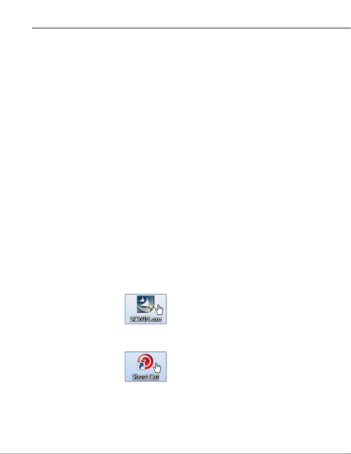
1. Install Short Cut by clicking on the install file icon. Get the install file
from either www.campbellsci.com, the ResourceDVD, or find it in
installations of LoggerNet, PC200W, PC400, or RTDAQ software.
2. The Short Cut installation should place a Short Cut icon on the desktop of
your computer. To open Short Cut, click on this icon.
2
CS470/CS471 Compact Bubbler System
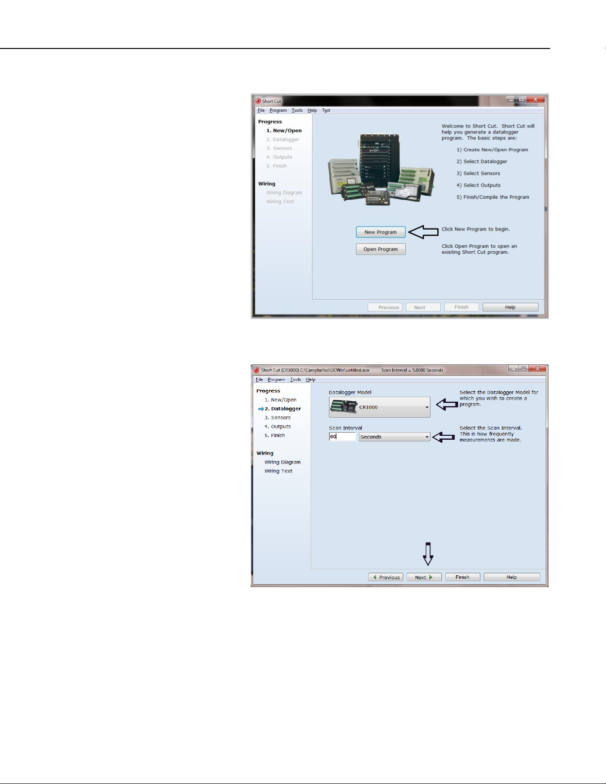
3. When Short Cut opens, select New Program.
4. Select Datalogger Model and Scan Interval (60 second or higher scan
interval is recommended). Click Next.
3
CS470/CS471 Compact Bubbler System
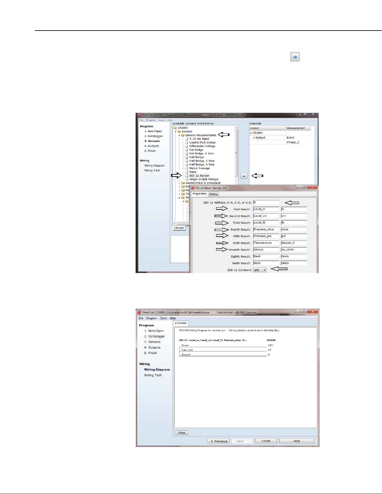
5. Under the Available Sensors and Devices list, select the Sensors |
Generic Measurements folder. Select SDI-12 Sensor, click to move
the selection to the Selected device window. Enter the result names and
units. The default SDI-12 address is 0 and the default SDI-12 command is
aM!. The SDI-12 address should only be changed from the default when
more than one sensor is connected to the same datalogger channel. The
SDI-12 command can be changed by clicking the SDI-12 Command box
and selecting one of the other options.
6. After selecting the sensor, click at the left of the screen on Wiring
Diagram to see how the sensor is to be wired to the datalogger. The
wiring diagram can be printed out now or after more sensors are added.
4
 Loading...