

Page 1
INSTRUCTION MANUAL
CS470/CS471 Compact
Copyright © 2009- 2014
Campbell Scientific, Inc.
Bubbler System
Revision: 7/14
Page 2

Page 3

Limited Warranty
“Products manufactured by CSI are warranted by CSI to be free from defects in
materials and workmanship under normal use and service for twelve months
from the date of shipment unless otherwise specified in the corresponding
product manual. (Product manuals are available for review online at
www.campbellsci.com.) Products not manufactured by CSI, but that are resold
by CSI, are warranted only to the limits extended by the original manufacturer.
Batteries, fine-wire thermocouples, desiccant, and other consumables have no
warranty. CSI’s obligation under this warranty is limited to repairing or
replacing (at CSI’s option) defective Products, which shall be the sole and
exclusive remedy under this warranty. The Customer assumes all costs of
removing, reinstalling, and shipping defective Products to CSI. CSI will return
such Products by surface carrier prepaid within the continental United States of
America. To all other locations, CSI will return such Products best way CIP
(port of entry) per Incoterms ® 2010. This warranty shall not apply to any
Products which have been subjected to modification, misuse, neglect, improper
service, accidents of nature, or shipping damage. This warranty is in lieu of all
other warranties, expressed or implied. The warranty for installation services
performed by CSI such as programming to customer specifications, electrical
connections to Products manufactured by CSI, and Product specific training, is
part of CSI's product warranty. CSI EXPRESSLY DISCLAIMS AND
EXCLUDES ANY IMPLIED WARRANTIES OF MERCHANTABILITY
OR FITNESS FOR A PARTICULAR PURPOSE. CSI hereby disclaims,
to the fullest extent allowed by applicable law, any and all warranties and
conditions with respect to the Products, whether express, implied or
statutory, other than those expressly provided herein.”
Page 4

Assistance
Products may not be returned without prior authorization. The following
contact information is for US and international customers residing in countries
served by Campbell Scientific, Inc. directly. Affiliate companies handle
repairs for customers within their territories. Please visit
www.campbellsci.com to determine which Campbell Scientific company serves
your country.
To obtain a Returned Materials Authorization (RMA), contact CAMPBELL
SCIENTIFIC, INC., phone (435) 227-9000. After an application engineer
determines the nature of the problem, an RMA number will be issued. Please
write this number clearly on the outside of the shipping container. Campbell
Scientific’s shipping address is:
CAMPBELL SCIENTIFIC, INC.
RMA#_____
815 West 1800 North
Logan, Utah 84321-1784
For all returns, the customer must fill out a “Statement of Product Cleanliness
and Decontamination” form and comply with the requirements specified in it.
The form is available from our web site at www.campbellsci.com/repair. A
completed form must be either emailed to repair@campbellsci.com or faxed to
(435) 227-9106. Campbell Scientific is unable to process any returns until we
receive this form. If the form is not received within three days of product
receipt or is incomplete, the product will be returned to the customer at the
customer’s expense. Campbell Scientific reserves the right to refuse service on
products that were exposed to contaminants that may cause health or safety
concerns for our employees.
Page 5

Precautions
DANGER — MANY HAZARDS ARE ASSOCIATED WITH INSTALLING, USING, MAINTAINING, AND WORKING ON OR AROUND
TRIPODS, TOWERS, AND ANY ATTACHMENTS TO TRIPODS AND TOWERS SUCH AS SENSORS, CROSSARMS, ENCLOSURES,
ANTENNAS, ETC. FAILURE TO PROPERLY AND COMPLETELY ASSEMBLE, INSTALL, OPERATE, USE, AND MAINTAIN TRIPODS,
TOWERS, AND ATTACHMENTS, AND FAILURE TO HEED WARNINGS, INCREASES THE RISK OF DEATH, ACCIDENT, SERIOUS
INJURY, PROPERTY DAMAGE, AND PRODUCT FAILURE. TAKE ALL REASONABLE PRECAUTIONS TO AVOID THESE HAZARDS.
CHECK WITH YOUR ORGANIZATION'S SAFETY COORDINATOR (OR POLICY) FOR PROCEDURES AND REQUIRED PROTECTIVE
EQUIPMENT PRIOR TO PERFORMING ANY WORK.
Use tripods, towers, and attachments to tripods and towers only for purposes for which they are designed. Do not exceed design
limits. Be familiar and comply with all instructions provided in product manuals. Manuals are available at www.campbellsci.com or
by telephoning (435) 227-9000 (USA). You are responsible for conformance with governing codes and regulations, including safety
regulations, and the integrity and location of structures or land to which towers, tripods, and any attachments are attached. Installation
sites should be evaluated and approved by a qualified engineer. If questions or concerns arise regarding installation, use, or
maintenance of tripods, towers, attachments, or electrical connections, consult with a licensed and qualified engineer or electrician.
General
• Prior to performing site or installation work, obtain required approvals and permits. Comply
with all governing structure-height regulations, such as those of the FAA in the USA.
• Use only qualified personnel for installation, use, and maintenance of tripods and towers, and
any attachments to tripods and towers. The use of licensed and qualified contractors is highly
recommended.
• Read all applicable instructions carefully and understand procedures thoroughly before
beginning work.
• Wear a hardhat and eye protection, and take other appropriate safety precautions while
working on or around tripods and towers.
• Do not climb tripods or towers at any time, and prohibit climbing by other persons. Take
reasonable precautions to secure tripod and tower sites from trespassers.
• Use only manufacturer recommended parts, materials, and tools.
Utility and Electrical
• You can be killed or sustain serious bodily injury if the tripod, tower, or attachments you are
installing, constructing, using, or maintaining, or a tool, stake, or anchor, come in contact with
overhead or underground utility lines.
• Maintain a distance of at least one-and-one-half times structure height, 20 feet, or the distance
required by applicable law, whichever is greater, between overhead utility lines and the
structure (tripod, tower, attachments, or tools).
• Prior to performing site or installation work, inform all utility companies and have all
underground utilities marked.
• Comply with all electrical codes. Electrical equipment and related grounding devices should
be installed by a licensed and qualified electrician.
Elevated Work and Weather
• Exercise extreme caution when performing elevated work.
• Use appropriate equipment and safety practices.
• During installation and maintenance, keep tower and tripod sites clear of un-trained or non-
essential personnel. Take precautions to prevent elevated tools and objects from dropping.
• Do not perform any work in inclement weather, including wind, rain, snow, lightning, etc.
Maintenance
• Periodically (at least yearly) check for wear and damage, including corrosion, stress cracks,
frayed cables, loose cable clamps, cable tightness, etc. and take necessary corrective actions.
• Periodically (at least yearly) check electrical ground connections.
WHILE EVERY ATTEMPT IS MADE TO EMBODY THE HIGHEST DEGREE OF SAFETY IN ALL CAMPBELL SCIENTIFIC PRODUCTS,
THE CUSTOMER ASSUMES ALL RISK FROM ANY INJURY RESULTING FROM IMPROPER INSTALLATION, USE, OR
MAINTENANCE OF TRIPODS, TOWERS, OR ATTACHMENTS TO TRIPODS AND TOWERS SUCH AS SENSORS, CROSSARMS,
ENCLOSURES, ANTENNAS, ETC.
Page 6

Page 7

Table of Contents
PDF viewers: These page numbers refer to the printed version of this document. Use the
PDF reader bookmarks tab for links to specific sections.
1. Introduction ................................................................. 1
2. Cautionary Statements ............................................... 1
3. Initial Inspection ......................................................... 1
3.1 Shipping Kit and Accessories .............................................................. 2
3.1.1 Shipping Kit .................................................................................. 2
3.1.2 Accessories ................................................................................... 2
4. Quickstart .................................................................... 2
5. Overview ...................................................................... 5
6. Specifications ............................................................. 5
7. Installation ................................................................... 6
7.1 DIP Switch Settings ............................................................................. 7
7.2 Installation/Water Depth Considerations ............................................. 7
7.3 Mounting the CS470/CS471 ................................................................ 8
7.4 Connect Tubing to the CS470/CS471 .................................................. 9
7.5 Bubble Chamber Installation................................................................ 9
7.6 Purging Function ................................................................................ 11
7.7 Wiring ................................................................................................ 12
7.8 Programming ...................................................................................... 14
7.8.1 CRBasic Programming ............................................................... 14
7.8.2 Edlog Programming .................................................................... 14
8. Operation ................................................................... 15
8.1 SDI-12 Commands ............................................................................. 15
8.2 Measurements at Fast Scan Rates ...................................................... 15
8.3 Long Cables ....................................................................................... 15
8.4 Measuring Multiple SDI-12 Sensors .................................................. 16
9. Maintenance .............................................................. 16
9.1 Replacing Tubing ............................................................................... 17
10. Troubleshooting........................................................ 17
10.1 Status LED ......................................................................................... 17
i
Page 8

Table of Contents
Appendices
Importing Short Cut Code ...................................... A-1
A.
A.1 Importing Short Cut Code into a Program Editor ............................ A-1
A.1.1 CRBasic Datalogger ................................................................. A-1
A.1.2 Edlog ........................................................................................ A-2
B. Example Programs .................................................. B-1
B.1 CRBasic Programs .......................................................................... B-1
B.1.1 Example CR200(X) Program ................................................... B-1
B.1.2 Example CR1000 Program ....................................................... B-2
B.2 Edlog Program................................................................................. B-3
C. 4 to 20 mA Operation .............................................. C-1
C.1 Setting Operating Parameters using DIP Switches .......................... C-2
D. SDI-12 Sensor Support ........................................... D-1
D.1 SDI-12 Command Basics ................................................................ D-1
D.1.1 Address Query Command (?!) ................................................. D-1
D.1.2 Change Address Command (aAb!) .......................................... D-1
D.1.3 Send Identification Command (aI!) .......................................... D-2
D.1.4 Start Measurement Commands (aM!) ...................................... D-2
D.1.5 Aborting a Measurement Command ........................................ D-2
D.1.6 Send Data Command (aDv!) .................................................... D-2
D.2 SDI-12 Transparent Mode ............................................................... D-3
D.2.1 CR200(X) Series Datalogger Example .................................... D-3
D.2.2 CR1000 Datalogger Example ................................................... D-4
D.2.3 CR10X Datalogger Example .................................................... D-5
D.3 Advanced SDI-12 Commands ......................................................... D-7
Figures
Tables
7-1. Securing the CS470/CS471 to a DIN Rail........................................... 8
7-2. Bubble Chamber Installation ............................................................. 10
7-3. Connection of the Bubble Tube ......................................................... 11
7-4. Purge Button and Status LED ........................................................... 12
7-5. CS470/CS471 Screw Terminals ........................................................ 13
C-1. Diagram to determine the maximum load resistance as a function
of the power supply. ..................................................................... C-1
D-1. CR200(X) example of using the SDI-12 transparent mode to
change the SDI-12 address from 0 to 1. ....................................... D-4
D-2. CR1000 example of using the SDI-12 transparent mode to
change the SDI-12 address from 3 to 1. Sensor is connected
to control port 1. ........................................................................... D-5
D-3. CR10X example of using the SDI-12 transparent mode to
change the SDI-12 address from 0 to 1. Sensor is connected
to control port 1. ........................................................................... D-6
7-1. Dip Switch Settings for SDI-12 Communications............................... 7
7-2. Datalogger Wiring ............................................................................. 13
ii
Page 9

Table of Contents
10-1. Status LED ......................................................................................... 17
D-1. CS470/CS471 SDI-12 Command and Response Set ...................... D-1
D-2. Send Data Return Values ................................................................ D-3
D-3. Advanced SDI-12 Commands ......................................................... D-7
iii
Page 10

Table of Contents
iv
Page 11

CS470/CS471 Compact Bubbler System
1. Introduction
The CS470 and CS471 are designed for general liquid level measurements.
They use SDI-12 or RS-232 communications protocols to communicate with a
SDI-12 or RS-232 recorder simplifying installation and programming.
2. Cautionary Statements
• READ AND UNDERSTAND the Precautions section at the front of this
manual.
• Remember that although the CS470/CS471 is designed to be a rugged and
reliable device for field use, it is also a highly precise scientific instrument
and should be handled as such.
• NEVER open the housing of the CS470/CS471. There are no user-
serviceable parts inside the sensor housing and any attempt to disassemble
the device will void the warranty.
• While connecting the tubing, keep contamination or moisture from
entering the tubing.
• Do not damage or kink the tubing during installation.
• Always use a sharp knife instead of scissors to cut the tubing.
3. Initial Inspection
• Upon receipt of the CS470/CS471, inspect the packaging for any signs of
shipping damage, and, if found, report the damage to the carrier in
accordance with policy. The contents of the package should also be
inspected and a claim filed if any shipping related damage is discovered.
• Care should be taken when opening the package not to damage or cut the
polyethylene tubing (if ordered). If there is any question about damage
having been caused to the tubing, a thorough inspection is prudent.
• The model number and serial number is printed on the housing. Check
this information against the shipping documentation to ensure that the
expected model number was received.
• Refer to Section 3.1, Shipping Kit and Accessories, to ensure you have all
of the components
1
Page 12
CS470/CS471 Compact Bubbler System
3.1 Shipping Kit and Accessories
3.1.1 Shipping Kit
The CS470/CS471 ships with:
• (1) Installation Kit (top DIN rail with fastening parts; screw terminal
• (2) #505 Screws
• (2) #6044 Grommets
• (1) #1113 Flat-bladed screwdriver
3.1.2 Accessories
The following are ordered as Common Accessories:
• CABLE4CBL-L 4-Conductor 22 AWG Cable — used to connect the
• Polyethylene Tubing, 3/8 inch OD, 1/8 inch ID (pn 25503) — used as
• OTT EPS-50 Bubble Chamber (pn 25502) — includes an NPT
blocks, pin jumpers)
CS470/CS471 to a datalogger. Cable length is user-specified. This
cable can either terminate in stripped and tinned leads that connect
directly to the datalogger or a connector that mates with a prewired
enclosure.
the measuring tube and is submerged in the liquid. Specify length, in
feet, when ordering.
adapter allows the bubble chamber to be connected to standard
plumbing materials.
4. Quickstart
Short Cut is an easy way to program your datalogger to measure the sensor and
assign datalogger wiring terminals. The following procedure shows using
Short Cut to program the CS470/CS471.
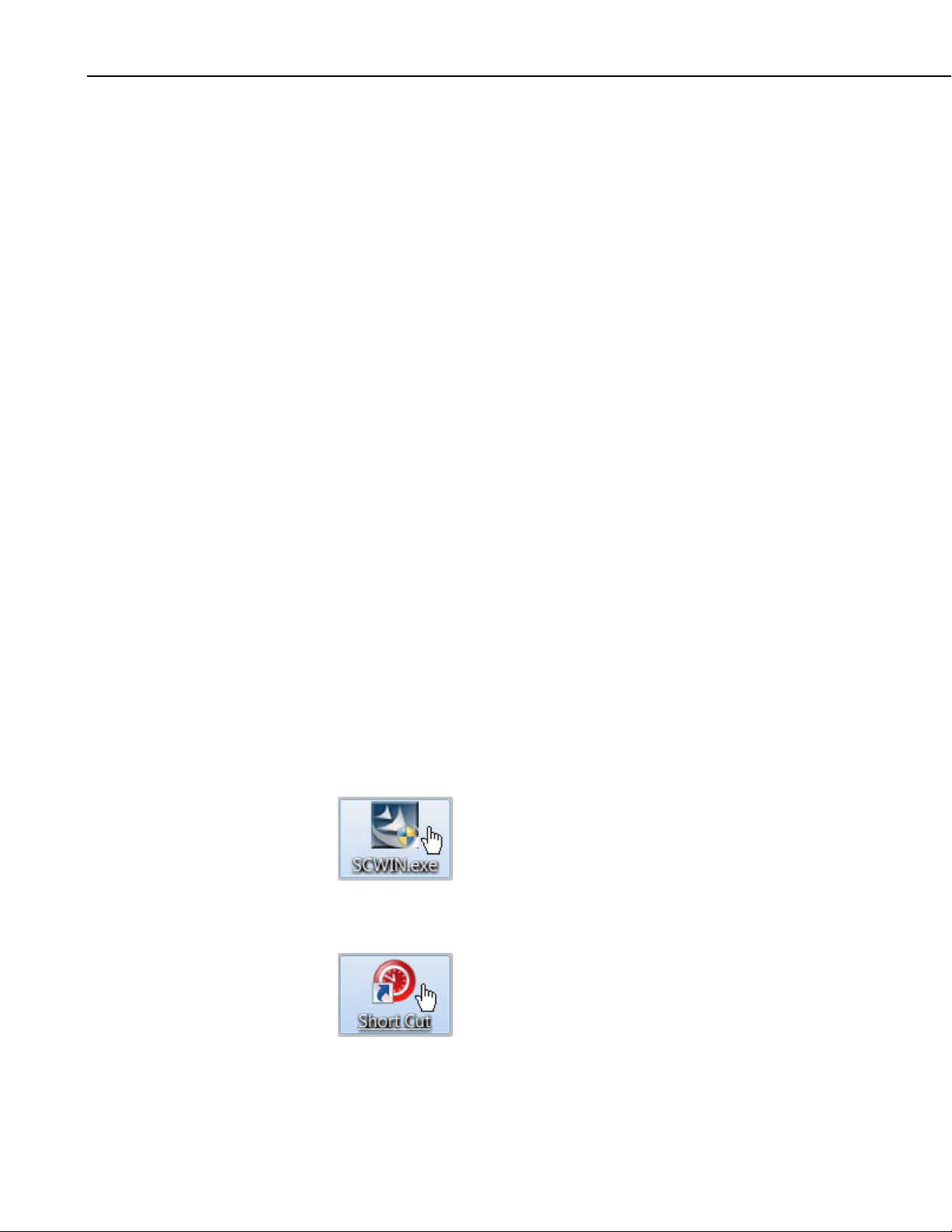
1. Install Short Cut by clicking on the install file icon. Get the install file
from either www.campbellsci.com, the ResourceDVD, or find it in
installations of LoggerNet, PC200W, PC400, or RTDAQ software.
2. The Short Cut installation should place a Short Cut icon on the desktop of
your computer. To open Short Cut, click on this icon.
2
Page 13
CS470/CS471 Compact Bubbler System
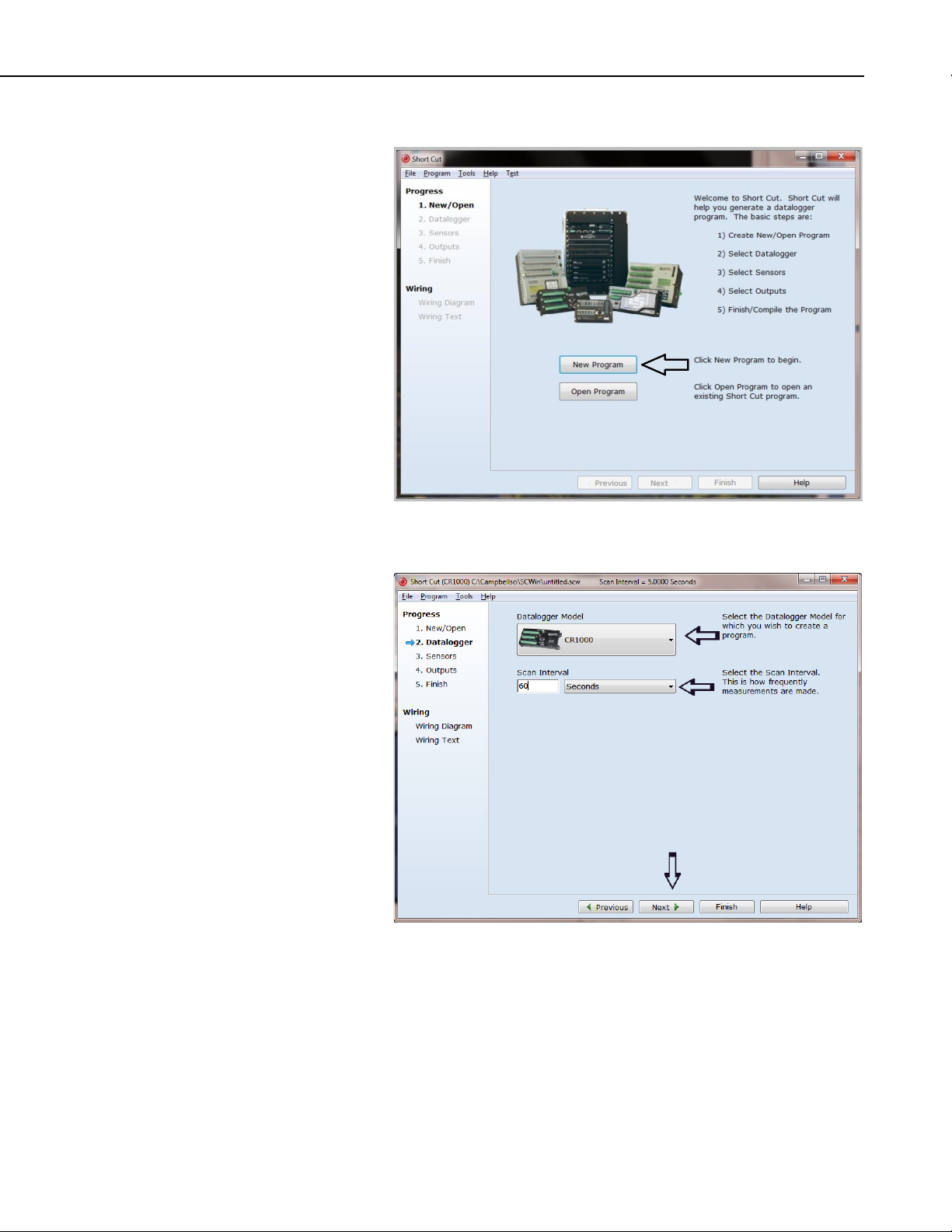
3. When Short Cut opens, select New Program.
4. Select Datalogger Model and Scan Interval (60 second or higher scan
interval is recommended). Click Next.
3
Page 14
CS470/CS471 Compact Bubbler System
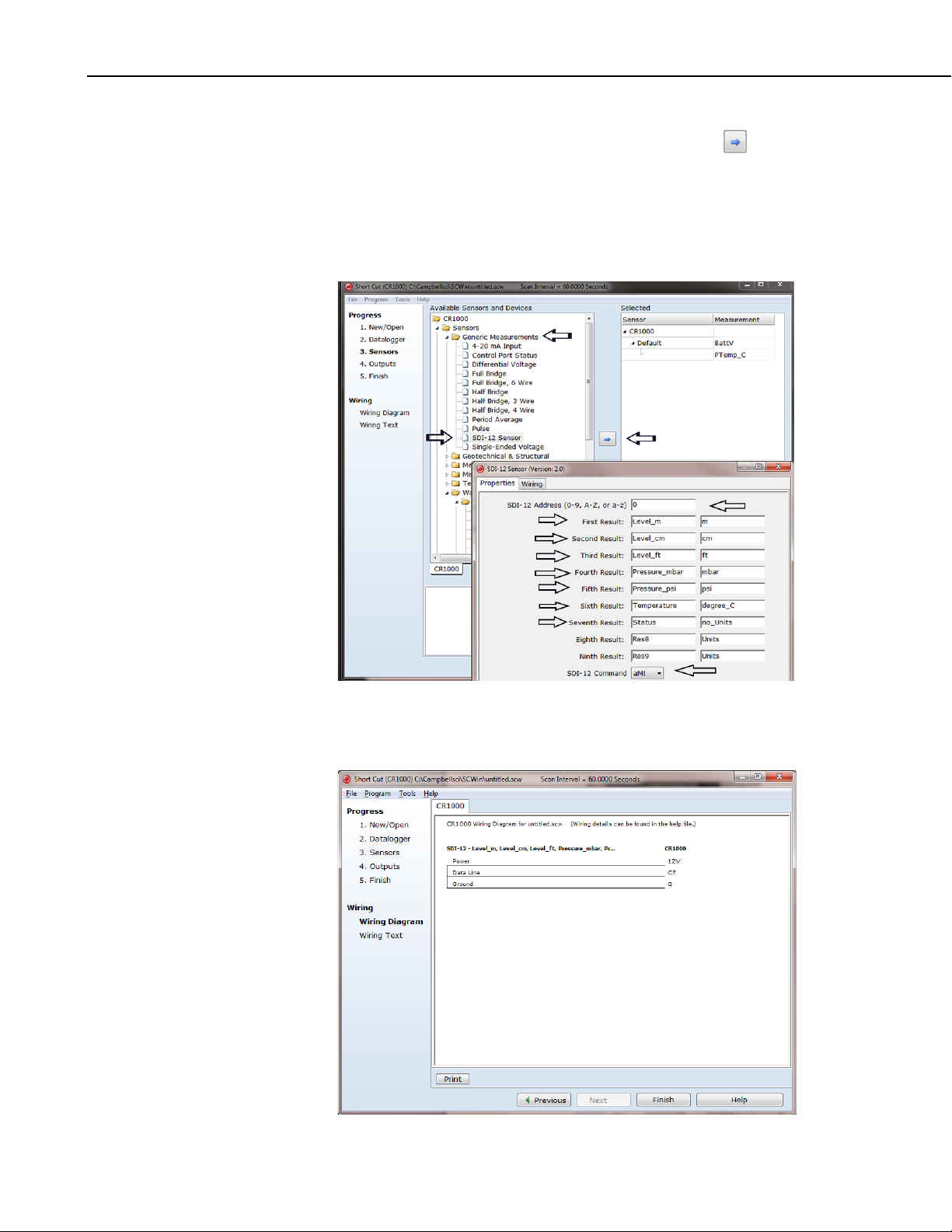
5. Under the Available Sensors and Devices list, select the Sensors |
Generic Measurements folder. Select SDI-12 Sensor, click to move
the selection to the Selected device window. Enter the result names and
units. The default SDI-12 address is 0 and the default SDI-12 command is
aM!. The SDI-12 address should only be changed from the default when
more than one sensor is connected to the same datalogger channel. The
SDI-12 command can be changed by clicking the SDI-12 Command box
and selecting one of the other options.
6. After selecting the sensor, click at the left of the screen on Wiring
Diagram to see how the sensor is to be wired to the datalogger. The
wiring diagram can be printed out now or after more sensors are added.
4
Page 15

5. Overview
CS470/CS471 Compact Bubbler System
7. Select any other sensors you have, then finish the remaining Short Cut
steps to complete the program. The remaining steps are outlined in Short
Cut Help, which is accessed by clicking on Help | Contents |
Programming Steps.
8. If LoggerNet, PC400, or PC200W is running on your PC, and the PC to
datalogger connection is active, you can click Finish in Short Cut and you
will be prompted to send the program just created to the datalogger.
9. If the sensor is connected to the datalogger, as shown in the wiring
diagram in step 6, check the output of the sensor in the datalogger support
software data display to make sure it is making reasonable measurements.
The CS470 and CS471 use the air bubble principle for measuring liquid level.
Generally, they measure ground or surface water level, but any liquid level can
be measured. Typical applications include agricultural water level/flow, water
wells, lakes, streams, and tanks. The CS470 and CS471 differ only in their
measurement accuracy.
Compressed air produced by a piston pump flows via a measuring tube into the
water to be measured. The pressure created in the measuring tube is directly
proportional to the water column above the bubble chamber. The
CS470/CS471 determines the barometric air and bubble pressure one after the
other. By taking the difference between the two signals, the CS470/CS471
calculates the height of the water level above the bubble chamber.
The CS470/CS471 contains a purge function. This clears the measuring tube
and the bubble chamber of any minor contamination by pumping a large
volume of air into the measuring tube.
By using an intelligent pump strategy, no air drying unit is necessary.
The CS470/CS471 has three communication options: SDI-12, 4 to 20 mA, or
RS-485 (SDI-12 protocol via a physical RS-485 interface). As an SDI-12
sensor, the CS470/CS471 is shipped with an address of 0.
The CS470 and CS471 are manufactured by OTT as model CBS.
6. Specifications
Features:
• Ideal for areas where submersed sensors can be damaged due to
corrosion, contamination, flood-related debris, lightning, or
vandalism
• Easy to maintain
• Robust pump design provides reliable operation
• Consistent accuracy ensured by drift-free measurements and offset
compensation using relative measurement
• Purge function clears the measuring tube and the bubble chamber of
contamination
5
Page 16

CS470/CS471 Compact Bubbler System
• Does not use pressurized nitrogen tank — requiring less frequent
• Existing tubes can be used
• Compatible with Campbell Scientific CRBasic dataloggers:
Power Requirements: 10 to 30 Vdc (typically supplied by the datalogger
Power Consumption: Quiescent current < 0.25 mA
Measurement/Communication Current:
Typical 320 mAh/day with 1 minute query interval
Typical 25 mAh/day with 15 min query interval
Measurement Time: 1 minute
Outputs: SDI-12 (version 1.3) 1200 Baud
4 to 20 mA
RS-484 (SDI-12 Protocol via RS-485 interface)
Measurement Ranges: 0 to 50 ft
attendance
CR200(X) series, CR800 series, CR1000, CR3000, and CR5000.
Also compatible with Edlog dataloggers: CR500, CR510, CR10(X),
and CR23X
7. Installation
Accuracy: CS470 Standard: ±0.02 ft
CS471 High Accuracy:
0 to 15 ft: ±0.01 ft
15 to 35 ft: ±0.065% of reading
35 to 50 ft: ±0.02 ft
Resolution: 0.003 ft/0.014 psi
Operating Temperature: –20 to 60 °C
Storage Temperature: –40 to 85 °C
Relative Humidity: 10 to 95% non-condensing
Measuring tube: 1/8 in. I.D, 3/8 in. O.D., 100.6 m (330 ft) maximum
length
Dimensions: 16.5 x 20.5 x 11.5 cm (6.5 x 8.1 x 4.5 in)
Weight: 1.5 kg (3.3 lb)
If you are programming your datalogger with Short Cut, skip Section 7.7,
Wiring, and Section 7.8, Programming. Short Cut does this work for you. See
Section 4, Quickstart, for a Short Cut tutorial.
6
Page 17

7.1 DIP Switch Settings
TABLE 7-1. Dip Switch Settings for
CS470/CS471 Compact Bubbler System
The default DIP switch settings are shown in TABLE 7-1. The default settings
support SDI-12 communications, which is the communication method typically
used by our dataloggers. The DIP switch settings need to be changed if using 4
to 20 mA communications (see Appendix C, 4 to 20 mA Operation).
SDI-12 Communications
SDI-12 Settings Switch Settings
1 ON
2 ON
3 OFF
4 NA
5 NA
6 NA
7 NA
8 NA
7.2 Installation/Water Depth Considerations
The CS470/CS471 and bubble chamber should be installed so that the tubing
has a continuous drop from the CS470/CS471 towards the bubble chamber.
Otherwise, moisture can collect in a hallow and potentially block the tubing
with the formation of drops.
The bubble chamber must be installed below the water at a fixed depth. The
maximum water depth is determined by the maximum tube length, which is
15.24 m (50 ft).
7
Page 18

CS470/CS471 Compact Bubbler System
For optimal measurement results, the bubble chamber should be horizontal and
aligned in the direction of water flow (maximum tolerance ±5°). The bubble
chamber has a ball-and-socket joint that adjusts to 15° in any direction.
7.3 Mounting the CS470/CS471
The CS470/CS471 electronic box should be in a dry and dust-free location
such as a Campbell Scientific enclosure. It mounts to an enclosure backplate
using DIN rails (included with shipped material). With the supplied grommets
and screws, connect the top DIN rails horizontally to the back panel of a
Campbell Scientific enclosure (see FIGURE 7-1).
With the top DIN rails installed, first attach the CS470/CS471 on the upper
edge of the top DIN rail and then press the underside against the top DIN rail
until it clicks into place.
To dismount the CS470/CS471, first press one locking device downwards and
pull the CS470/CS471 slightly forwards at this point. Press the second locking
device downwards and remove the CS470/CS471 upwards from the top DIN
rail.
8
FIGURE 7-1. Securing the CS470/CS471 to a DIN Rail
Page 19

CS470/CS471 Compact Bubbler System
7.4 Connect Tubing to the CS470/CS471
1. Cut the bubble tube at a 90° angle with a sharp knife (not scissors).
2. Insert the tubing as far as possible into the tube fitting.
3. Rotate the nut until finger tight.
4. Tighten the nut with a wrench about one and one-quarter turns.
7.5 Bubble Chamber Installation
1. Install conduit (metal or plastic) from the CS470/CS471 to where the
bubble chamber will be located. There should be a continuous drop from
the CS470/CS471 to the bubble chamber (see FIGURE 7-2).
9
Page 20

CS470/CS471 Compact Bubbler System
10
FIGURE 7-2. Bubble Chamber Installation
2. Fasten the conduit in place
3. Attach an elbow or tee joint at the bubble chamber location. The elbow or
tee joint should terminate with a 2-inch NPT female threaded connection.
4. Route the tubing through the conduit.
5. Cut the tubing at a 90° angle with a sharp knife (not scissors).
6. Detach the NPT adapter from the bubble chamber by unscrewing the three
hexagonal screws of the bubble chamber’s flange (see FIGURE 7-3).
Page 21

CS470/CS471 Compact Bubbler System
NOTE
FIGURE 7-3. Connection of the Bubble Tube
7. Install the NPT adapter on the end of the elbow or tee joint.
8. Activate the CS470/CS471 while immersing the bubble chamber. The
CS470/CS471 needs to be activated, so that the piston pump is operating
during this procedure.
9. Insert the tubing as far as possible into the bubble chamber’s tube fitting
10. Rotate the nut until finger tight.
11. While holding the bubble chamber steady, tighten the nut with a wrench
about one and one-quarter turns.
12. Install the bubble chamber on the NPT adapter.
For optimal measurement results, the bubble chamber must be
adjusted to be horizontal and aligned in the direction of flow
(maximum tolerance ±5°). The 25502 bubble chamber has a balland-socket joint which allows for adjustments by 15° in any
direction.
7.6 Purging Function
On the front of the CS470/CS471, there is a pump membrane button (see
FIGURE 7-4). Pressing the button activates the purge function for as long as it
is pressed. The Status LED lights for approximately 2 seconds. With an
activated purge function, the sensor pumps a large amount of air through the
11
Page 22

CS470/CS471 Compact Bubbler System
NOTE
NOTE
measuring tube for the required time period. The purge function can also be
activated via an SDI-12 command.
Press the membrane button for at least one second as otherwise the
error is called and displayed at the Status LED.
FIGURE 7-4. Purge Button and Status LED
7.7 Wiring
All electrical connections are made using two screw terminal strips (supplied)
at terminal blocks A and B on the underside of the CS470/CS471 (see FIGURE
7-5).
Although the CS470/CS471 has three interfaces available, our dataloggers
typically use SDI-12, and, therefore, only the SDI-12 connections will be
addressed here (for information about 4 to 20 mA communication, see
Appendix C).
It is recommended to power down your system before wiring the
CS470/CS471. SDI-12 communication only requires a four-wire connection
(see TABLE 7-2). Use CABLE4CBL-L 4-conductor 22 AWG cable.
The shield wire plays an important role in noise emissions and
susceptibility as well as transient protection.
12
Page 23

CS470/CS471 Compact Bubbler System
TABLE 7-2. Datalogger Wiring
FIGURE 7-5. CS470/CS471 Screw Terminals
Terminal
Terminal
Number
Function
CR800, CR850,
CR1000, CR3000,
CR23X, CR10(X),
CR500, CR510
CR5000
CR200(X)
A 1 12 V power 12V 12V Battery+
A 4 Power Ground G G G
B 3 SDI-12 Data Odd Numbered
SDI-12 C1/SDI-12
Control Port
(C1, C3, …)
B 4 SDI-12 Ground G G G
13
Page 24

CS470/CS471 Compact Bubbler System
NOTE
7.8 Programming
Short Cut is the best source for up-to-date datalogger programming code.
Programming code is needed,
• when creating a program for a new datalogger installation
• when adding sensors to an existing datalogger program
If your data acquisition requirements are simple, you can probably create and
maintain a datalogger program exclusively with Short Cut. If your data
acquisition needs are more complex, the files that Short Cut creates are a great
source for programming code to start a new program or add to an existing
custom program.
Short Cut cannot edit programs after they are imported and edited
in CRBasic Editor.
A Short Cut tutorial is available in Section 4, Quickstart. If you wish to import
Short Cut code into either Edlog or CRBasic Editor to create or add to a
customized program, follow the procedure in Appendix A.1, Importing Short
Cut Code into a Program Editor. Programming basics for CRBasic and Edlog
dataloggers are provided in the following sections. Complete program
examples for select dataloggers can be found in Appendix B, Example
Programs.
7.8.1 CRBasic Programming
The SDI12Recorder() measurement instruction programs CRBasic
dataloggers (CR200(X) series, CR800 series, CR1000, CR3000, and CR5000)
to measure the CS470/CS471 sensor. This instruction sends a request to the
sensor to make a measurement and then retrieves the measurement from the
sensor. See Section 8.1, SDI-12 Commands, for more information.
When using a CR200(X), the SDI12Recorder() instruction has the following
syntax:
SDI12Recorder(Destination,OutString,Multiplier,Offset)
For the other CRBasic dataloggers, the SDI12Recorder() instruction has the
following syntax:
SDI12Recorder(Destination, SDIPort, SDIAddress, “SDICommand”,
Multiplier, Offset)
7.8.2 Edlog Programming
Edlog dataloggers read the CS470/CS471 using the SDI-12 Recorder (P105)
instruction.
Please note that Edlog only allocates one input location for the SDI-12
Recorder (P105) instruction. Seven input locations are required for the SDI12 M! command. The additional input locations need to be inserted manually
using the Input Location Editor. To get into the Input Location Editor, select
Edit/Input Labels or press the F5 key. Once in the Input Location Editor,
do the following:
14
Page 25

1. Choose Edit/Insert Block.
NOTE
NOTE
2. After the Insert Block dialog box appears, type in a base name for the
input locations. Each input location will have the base name with an
underscore and a consecutive number.
3. In the Start Address field, type in the number of the first input location.
4. In the Number of InLocs field, type in 7 and select OK.
8. Operation
8.1 SDI-12 Commands
This section briefly describes using the SDI-12 commands.
Additional SDI-12 information is available at Appendix D,
SDI-12 Sensor Support, www.sdi-12.org, or
www.youtube.com/user/CampbellScientific
CRBasic instruction SDI12Recorder() measures the CS470/CS471 sensor
using the Start Measurement (aM!) command. The “a” is the address of the
sensor and “!” is the command terminator. The sensor returns the following
seven values.
CS470/CS471 Compact Bubbler System
.
1. Level [m]; resolution: 0.001 m
2. Level [cm]; resolution: 1 cm
3. Level [ft]; resolution: 0.01 ft
4. Pressure [mbar]; resolution: 0.01 mbar
5. Pressure [psi]; resolution: 0.001 psi
6. Temperature [°C]; resolution: 0.1 °C
7. Status
A measurement is initiated with the aM! command. To this command, the
sensor responds with the time until the measurement data are available and the
number of values to be returned when one or more subsequent aD! commands
are issued.
8.2 Measurements at Fast Scan Rates
Using the SlowSequence() function allows the SDI-12 instruction to run as a
background process, causing minimum interference to other measurements that
use the analog hardware. Measuring the sensor in a SlowSequence() section of
the program allows faster programs to run as the main scan.
For the CR5000, use a control port rather than the SDI-12 port to
allow the SDI12recorder instruction to run in the slow sequence.
8.3 Long Cables
Digital data transfer eliminates offset errors due to cable lengths. However,
digital communications can break down when cables are too long, resulting in
either no response from the sensor or corrupted readings. The original SDI-12
standard specifies the maximum total cable length to be 61 meters (200 feet).
To ensure proper operation with long cables, follow these guidelines:
15
Page 26

CS470/CS471 Compact Bubbler System
• Use low capacitance, low resistance, screened cable (as fitted by Campbell
Scientific) to reach distances of several hundred meters.
• Ensure that the power ground cable has low resistance and is connected to
the same ground reference as the datalogger control ports.
• Be aware that “daisy-chaining” sensors reduces the maximum cable length
roughly in proportion to the number of sensors connected in parallel.
8.4 Measuring Multiple SDI-12 Sensors
Up to ten CS470/CS471 sensors or other SDI-12 sensors can be connected to a
single datalogger control port. Each SDI-12 device must have a unique SDI-12
address of 0 and 9, A to Z, or a to z. See Appendix D, SDI-12 Sensor Support,
for more information.
9. Maintenance
Never open the CS470/CS471 housing! There are no adjustments or control
elements inside the housing!
The CS470/CS471 itself is maintenance free. The manufacturer recommends
checking the measuring tube and bubble chamber at regular intervals and
cleaning as required. For every visit, you should do the following:
• Collect data.
• Visually inspect wiring and physical conditions.
• Check battery condition (inspect physical appearance and use a keyboard
display or laptop to view the battery voltage).
• Check all sensor readings; adjust level offsets if necessary.
• Check recent data.
• Check the bubble chamber quarterly for sand buildup and weed
infiltration. For light sand buildup, clean the bubble chamber using the
purge function, and for heavier buildup or weed infiltration, clean the
bubble chamber carefully manually (do not change the position of the
bubble chamber).
• Activate the purge function by pressing the membrane button. Pump and
check whether air bubbles rise out of the bubble chamber. If not, check
whether the bubble chamber is blocked, and/or whether the measuring tube
is leaking or blocked.
After 15 years of operation, test the measuring tube for tightness/pressure
resistance; repeat this test roughly every two years thereafter.
16
Page 27

9.1 Replacing Tubing
TABLE 10-1. Status LED
1. Untighten the nut securing the tubing to the hose connection.
2. Pull out tubing.
3. Untighten the nut securing the tubing to the bubble chamber.
4. Pull out tubing.
5. Follow procedures provided in Sections 7.4, Connect Tubing to the
CS470/CS471, and 7.5, Bubble Chamber Installation, to reconnect the
tubing.
10. Troubleshooting
10.1 Status LED
For the display of any error states that may occur, the CS470/CS471 has a
Status LED on the front of the device.
The following error states can arise:
CS470/CS471 Compact Bubbler System
1 x flash level too low (< 5 cm)
2 x flash level too high (range exceeded)
3 x flash power supply too low
4 x flash pump motor overloaded
5 x flash watchdog error
6 x flash data memory defective
7 x flash data bus defective
8 x flash analog converter defective
9 x flash measuring cell defective
The CS470/CS471 shows an error state when it arises and for approximately 2
minutes after pressing the pump membrane button.
The defective error states signify hardware problems that can only be rectified
by the CS470/CS471 manufacturer repair center. The watchdog error error
state means that the CS470/CS471 has been restarted. No intervention is
necessary.
17
Page 28

CS470/CS471 Compact Bubbler System
NOTE
Any error states arising can be displayed as follows:
Press pump membrane button briefly (< 1 sec). The LED lights
st
once for a longer period as confirmation, then pauses. 1
nd
state arising, then pause. 2
error state arising, then pause. LED
error
lights continue until all error states arising have flashed. The
CS470/CS471 repeats all error states arising for approximately
two minutes.
The most common causes for erroneous data include:
• poor sensor connections to the datalogger
• damaged cables
• damaged transducers
Problem:
Unit will not respond when attempting serial communications.
Suggestion:
Check the power and signal lines to ensure proper connection to the datalogger.
Check the datalogger program to ensure that the same port the SDI-12 data line
is connected to is specified in the measurement instruction.
18
Page 29

NOTE
Appendix A. Importing Short Cut Code
This tutorial shows:
• How to import a Short Cut program into a program editor for
additional refinement.
• How to import a wiring diagram from Short Cut into the comments of
a custom program.
A.1 Importing Short Cut Code into a Program Editor
Short Cut creates files that can be imported into either CRBasic Editor or
Edlog program editor. These files normally reside in the
C:\campbellsci\SCWin folder and have the following extensions:
• .DEF (wiring and memory usage information)
• .CR2 (CR200(X) datalogger code)
• .CR1 (CR1000 datalogger code)
• .CR8 (CR800 datalogger code)
• .CR3 (CR3000 datalogger code)
• .CR5 (CR5000 datalogger code)
• .DLD (contain code for CR10(X), CR23X, CR500, or CR510
dataloggers)
The following procedures show how to import these files for editing.
A.1.1 CRBasic Datalogger
Use the following procedure to import Short Cut code into CRBasic Editor
(CR200(X), CR1000, CR800, CR3000, CR5000 dataloggers).
1. Create the Short Cut program following the procedure in Section 4,
Quickstart. Finish the program and exit Short Cut. Make note of the file
name used when saving the Short Cut program.
2. Open CRBasic Editor.
3. Click File | Open. Assuming the default paths were used when Short Cut
was installed, navigate to C:\CampbellSci\SCWin folder. The file of
interest has a “.CR2”, “.CR1”, “.CR8”, “.CR3, or “.CR5” extension, for
CR200(X), CR1000, CR800, CR3000, or CR5000 dataloggers,
respectively. Select the file and click Open.
4. Immediately save the file in a folder different from \Campbellsci\SCWin,
or save the file with a different file name.
Once the file is edited with CRBasic Editor, Short Cut can no
longer be used to edit the datalogger program. Change the name
of the program file or move it, or Short Cut may overwrite it next
time it is used.
5. The program can now be edited, saved, and sent to the datalogger.
A-1
Page 30

Appendix A. Importing Short Cut Code
NOTE
6. Import wiring information to the program by opening the associated .DEF
file. Copy and paste the section beginning with heading “-Wiring for
CRXXX–” into the CRBasic program, usually at the head of the file.
After pasting, edit the information such that a ' character (single quotation
mark) begins each line. This character instructs the datalogger compiler to
ignore the line when compiling the datalogger code.
A.1.2 Edlog
Use the following procedure to import Short Cut code into the Edlog program
editor (CR10(X), CR500, CR510, and CR23X dataloggers).
1. Create the Short Cut program following the procedure in Section 4,
Quickstart. Finish the program and exit Short Cut. Make note of the file
name used when saving the Short Cut program.
2. Open Edlog.
3. Click File | Document DLD File. Assuming the default paths were used
when Short Cut was installed, navigate to C:\CampbellSci\SCWin folder.
The file of interest has a “.DLD” extension. Select the file and click
Open. The .dld file, which is a type of ASCII machine code, is imported,
documented, and, when saved, given a “.CSI” extension.
4. Immediately save the file in a folder different from \Campbellsci\SCWin,
or save the file with a different file name.
Once the file is edited with Edlog, Short Cut can no longer be used
to edit the program. Change the name of the program file or move
it, or Short Cut may overwrite it.
5. The program can now be edited, saved, and sent to the datalogger.
6. Import wiring information to the program by opening the associated .DEF
file. Copy and paste the section beginning with heading “-Wiring for
CRXXX–” into the Edlog program, usually at the head of the file. After
pasting, edit the information such that a ; (semicolon) begins each line,
which instructs the datalogger compiler to ignore the line when compiling
the datalogger code.
A-2
Page 31

Appendix B. Example Programs
B.1 CRBasic Programs
B.1.1 Example CR200(X) Program
'CR200 Series
'Declare the variable for the water level measurement
Public CS470(7)
'Rename the variable names
Alias CS470(1)=Level_m
Alias CS470(2)=Level_cm
Alias CS470(3)=Level_ft
Alias CS470(4)=Pressure_mbar
Alias CS470(5)=Pressure_psi
Alias CS470(6)=Temperature_C
Alias CS470(7)=Status
'Define a data table for 60 minute maximum and minimums
DataTable(Hourly,True,-1)
DataInterval(0,60,Min)
Maximum(1,Level_ft,0,0)
Minimum(1,Level_ft,0,0)
Maximum(1,Temp_C,0,0)
Minimum(1,Temp_C,0,0)
EndTable
'Read sensor every 60 seconds
BeginProg
Scan(60,sec)
'Code for SDI-12 measurements:
SDI12Recorder(CS470,0M!,1,0)
'Call the data table:
CallTable(Hourly)
NextScan
EndProg
B-1
Page 32

Appendix B. Example Programs
B.1.2 Example CR1000 Program
'CR1000 Series Datalogger
'Declare the variable for the water level measurement
Public CS470(7)
'Rename the variable names
Alias CS470(1)=Level_m
Alias CS470(2)=Level_cm
Alias CS470(3)=Level_ft
Alias CS470(4)=Pressure_mbar
Alias CS470(5)=Pressure_psi
Alias CS470(6)=Temperature_C
Alias CS470(7)=Status
'Define a data table for 60 minute maximum and minimums
DataTable(Hourly,True,-1)
DataInterval(0,60,Min,10)
Maximum(1,Level_ft,FP2,0,0)
Minimum(1,Level_ft,FP2,0,0)
Maximum(1,Temperature_C,FP2,0,0)
Minimum(1,Temperature_C,FP2,0,0)
EndTable
'Read sensor every 60 seconds
BeginProg
Scan(60,sec,1,0)
'Code for SDI-12 measurements:
SDI12Recorder(CS470,”0”,”M!”,1,0)
'Call the data table:
CallTable(Hourly)
NextScan
EndProg
B-2
Page 33

B.2 Edlog Program
NOTE
Below is a portion of a CR10X program that measures the CS470/CS471.
The instructions below do not store data in final storage.
Instruction 92, Instruction 77 and processing instructions such as
Instruction 70 are required to store the data permanently.
;{CR10X}
;
*Table 1 Program
01: 60 Execution Interval (seconds)
1: SDI-12 Recorder (P105)
1: 0 SDI-12 Address
2: 0 Start Measurement (aM0!)
3: 1 Port ;this is where the SDI-12 signal wire is connected
4: 1 Loc[Level_m ]
5: 1.0 Mult
6: 0.0 Offset
*Table 2 Program
02: 0.000 Execution Interval (seconds)
*Table 3 Subroutines
End Program
After this command is executed, the input location with the datalogger called
“Level-m” holds the measured value for Level, reported in meters. The result
may be further processed with the datalogger or stored to final storage
memory. Note that Port 1 specifies that the SDI-12 data line is to be connected
to the Port C1. Using the Inloc editor, allocate seven locations to allow for the
entire string of variables that will be provided by the CS470/CS471.
Appendix B. Example Programs
B-3
Page 34

Appendix B. Example Programs
B-4
Page 35

Appendix C. 4 to 20 mA Operation
The load resistance connected to the CS470/CS471 must not exceed a specific
maximum value. This value depends on the level of the supply voltage of the
CS470/CS471. If the load resistance is greater, the output current can no
longer be evaluated. Smaller load resistances are allowed.
• Read off the maximum load resistance for your power supply from
FIGURE C-1.
Example: Power supply 18 volt max. load resistance 450 Ohm.
The CS470/CS471 delivers an output current corresponding to the measured
value for a load resistance of up to 450 Ohm.
• Dimension the connected electrical circuit accordingly. Check the input
resistance of the connected peripheral.
FIGURE C-1. Diagram to determine the maximum load resistance as a
function of the power supply.
C-1
Page 36

Appendix C. 4 to 20 mA Operation
C.1 Setting Operating Parameters using DIP
Switches
The following 4 to 20 mA operating parameters can be set with DIP switches.
DIP switches 1, 2, and 3 are reserved for the SDI-12 interface.
Setting measurement type to level or depth
• Level Measurement – Set DIP Switch 4 to the OFF position.
• Depth Measurement – Set DIP Switch 4 to the ON position.
Scaling the measurement
With DIPS 5 and 6 you can scale the available measuring range to a smaller
range. Where the whole measuring range is not required, this has the
advantage of increasing the resolution.
• 50 ft (not scaled) – DIPS 5 and 6 to the ON position.
• 25 ft – DIP 5 to the OFF position, DIP 6 to the ON position.
• 12 ft – DIP 5 to the ON position, DIP 6 to the OFF position.
• 6 ft – DIPS 5 and 6 to the OFF position.
Setting the measurement system
Use DIP 7 to set the engineering units of the measurement.
• Metric – DIP 7 to OFF.
• Imperial – DIP 7 to ON.
Setting measurement type
Use DIP 8 to set water level or pressure units.
• Water Level – DIP 8 to OFF.
• Pressure – DIP 8 to ON.
C-2
Page 37

TABLE D-1. CS470/CS471 SDI-12 Command and Response Set
Appendix D. SDI-12 Sensor Support
D.1 SDI-12 Command Basics
SDI-12 commands have three components:
Sensor address (a) – a single character, and is the first character of the
command. The default address of zero (0) can be used unless multiple sensors
are connected to the same port.
Command body (e.g., M1) – an upper case letter (the “command”) followed by
alphanumeric qualifiers.
Command termination (!) – an exclamation mark.
An active sensor responds to each command. Responses have several standard
forms and terminate with <CR><LF> (carriage return – line feed). Standard
SDI-12 commands supported by the CS470/CS471 are listed in TABLE D-1.
Appendix D.3 provides advanced commands.
Name Command Response
Acknowledge
Active
Send
Identification
Change
Address
Address
Query
Start
Measurement
Send Data aD0! a<values><CR><LF>
Start
Verification
a! a<CR><LF>
aI! allccccccccmmmmmmvvvxxx...xx<CR><LF>
aAb! b<CR><LF>
?! a<CR><LF>
aM! atttn<CR><LF>
aV! atttn
D.1.1 Address Query Command (?!)
Command ?! requests the address of the connected sensor. The sensor replies
to the query with the address, a.
D.1.2 Change Address Command (aAb!)
Sensor address is changed with command aAb!, where a is the current address
and b is the new address. For example, to change an address from 0 to 2, the
command is 0A2!. The sensor responds with the new address b, which in this
case is 2.
D-1
Page 38

Appendix D. SDI-12 Sensor Support
D.1.3 Send Identification Command (aI!)
Sensor identifiers are requested by issuing command aI!. The reply is defined
by the sensor manufacturer, but usually includes the sensor address, SDI-12
version, manufacturer’s name, and sensor model information. Serial number or
other sensor specific information may also be included.
An example of a response from the aI! command is:
13OTT HACH CBS107
Where:
SDI-12 version =1.3
Manufacturer = OTT HACH
Sensor model = CBS
Sensor serial number = 107
D.1.4 Start Measurement Commands (aM!)
A measurement is initiated with M! commands. The response to each
command has the form atttnn, where
a = sensor address
ttt = time, in seconds, until measurement data are available
nn = the number of values to be returned when one or more subsequent D!
commands are issued.
D.1.5 Aborting a Measurement Command
A measurement command (M!) is aborted when any other valid command is
sent to the sensor.
D.1.6 Send Data Command (aDv!)
This command requests data from the sensor. It is normally issued
automatically by the datalogger after measurement commands aMv!. In
transparent mode, the user asserts this command to obtain data. If the expected
number of data values are not returned in response to an aD0! command, the
datalogger issues aD1!. TABLE D-2 shows the values returned when using the
send data command.
D-2
Page 39

Appendix D. SDI-12 Sensor Support
TABLE D-2. Send Data Return Values
SDI-12
Command
D! 7 Level [m], Level [cm], Level [ft],
D0! 1 Level [m]; resolution: 0.001 m
D1! 1 Level [cm]; resolution: 1 cm
D2! 1 Level [ft]; resolution: 0.01 ft
D3! 1 Pressure [mbar]; resolution: 0.01 mbar
D4! 1 Pressure [psi]; resolution: 0.001 psi
D5! 1 Temperature [°C]; resolution: 0.1 °C
D6! 1 Status
Number of
Values
Returned
D.2 SDI-12 Transparent Mode
System operators can manually interrogate and enter settings in probes using
transparent mode. Transparent mode is useful in troubleshooting SDI-12
systems because it allows direct communication with probes. Datalogger
security may need to be unlocked before transparent mode can be activated.
Values Returned
Pressure [mbar], Pressure [psi],
Temperature [°C], Status
Transparent mode is entered while the PC is in telecommunications with the
datalogger through a terminal emulator program. It is easily accessed through
Campbell Scientific datalogger support software, but is also accessible with
terminal emulator programs such as Windows HyperTerminal. Datalogger
keyboards and displays cannot be used.
The terminal emulator is accessed by navigating to the Datalogger menu in
PC200W, the Tools menu in PC400, or the Datalogger menu in the Connect
screen of LoggerNet.
The following examples show how to use LoggerNet software to enter
transparent mode and change the SDI-12 address of a CS470/CS471 sensor.
The same steps are used to enter transparent mode with PC200W and PC400
software after accessing the terminal emulator as previously described.
D.2.1 CR200(X) Series Datalogger Example
1. Connect a single CS470/CS471 to the CR200(X) (see TABLE 7-2)
2. In the LoggerNet Connect screen, navigate to the Datalogger menu and
select Terminal Emulator. The terminal emulator window will open. In
the Select Device menu, located in the lower left-hand side of the window,
select the CR200Series station.
3. Click on the Open Terminal button.
D-3
Page 40

Appendix D. SDI-12 Sensor Support
4. Press the <enter> key until the datalogger responds with the CR2XX>
5. To query the C470/CS471 for its current SDI-12 address, key in ?! <enter>
6. To change the SDI-12 address, key in aAb! <enter>, where a is the current
prompt. At the CR2XX> prompt, make sure the All Caps Mode box is
checked and enter the command SDI12 <enter>. The response SDI12>
indicates that the C470/CS471 is ready to accept SDI-12 commands.
and the C470/CS471 will respond with its SDI-12 address. If no
characters are typed within 60 seconds, then the mode is exited. In that
case, simply enter the command SDI12 again and press <enter>.
address from the above step and b is the new address (see FIGURE D-1).
The C470/CS471 will change its address and the datalogger will respond
with the new address. To exit SDI-12 transparent mode, select the Close
Terminal button.
FIGURE D-1. CR200(X) example of using the SDI-12 transparent
mode to change the SDI-12 address from 0 to 1.
D.2.2 CR1000 Datalogger Example
1. Connect a CS470/CS471 to the CR1000 (see TABLE 7-2).
2. In the LoggerNet Connect screen navigate to the Datalogger menu
and select Terminal Emulator. The terminal emulator window will
open. In the Select Device menu, located in the lower left-hand side
of the window, select the CR1000 station.
3. Click on the Open Terminal button.
4. Press the <enter> key until the datalogger responds with the CR1000>
prompt. At the CR1000> prompt, make sure the All Caps Mode box
is checked and enter the command SDI12 <enter>. At the Enter Cx
Port 1, 3, 5, or 7 prompt, key in the control port number where the
CS470/CS471 is connected and press <enter>. The response Entering
SDI12 Terminal indicates that the CS470/CS471 is ready to accept
SDI-12 commands.
5. To query the CS470/CS471 for its current SDI-12 address, key in ?!
<enter> and the CS470/CS471 will respond with its SDI-12 address.
If no characters are typed within 60 seconds, then the mode is exited.
D-4
Page 41

Appendix D. SDI-12 Sensor Support
In that case, simply enter the command SDI12 again, press <enter>,
and key in the correct control port number when prompted.
6. To change the SDI-12 address, key in aAb! <enter>, where a is the
current address from the above step and b is the new address (see
FIGURE D-2). The C470/CS471 will change its address and the
datalogger will respond with the new address. To exit SDI-12
transparent mode, select the Close Terminal button.
FIGURE D-2. CR1000 example of using the SDI-12 transparent mode
to change the SDI-12 address from 3 to 1. Sensor is connected to
control port 1.
D.2.3 CR10X Datalogger Example
1. Connect a CS470/CS471 to the CR10(X) (see TABLE 7-2).
2. Download a datalogger program that contains the SDI-12 Recorder (P105)
instruction with valid entries for each parameter. Make sure that
parameter 3 of the P105 instruction matches the control port number where
the CS470/CS471 is connected.
3. In the LoggerNet Connect screen navigate to the Datalogger menu and
select Terminal Emulator. The terminal emulator window will open. In
the Select Device menu, located in the lower left-hand side of the window,
select the CR10X station.
4. Click on the Open Terminal button.
5. Press the <enter> key until the datalogger responds with the * prompt.
6. To activate the SDI-12 Transparent Mode on control port p, enter pX
<enter>. For this example, key in 1X <enter>. The datalogger will
respond with entering SDI-12. If any invalid SDI-12 command is issued,
the datalogger will exit the SDI-12 Transparent Mode.
D-5
Page 42

Appendix D. SDI-12 Sensor Support
7. To query the CS470/CS471 for its current SDI-12 address, enter the
8. To change the SDI-12 address, enter the command aAb!; where a is the
9. Activate the SDI-12 Transparent Mode on Control Port 1 again by entering
10. To exit the SDI-12 Transparent Mode, enter *.
command ?!. The CS470/CS471 will respond with the current SDI-12
address.
current address from the above step and b is the new address. The
CS470/CS471 will change its address and the datalogger will exit the SDI12 Transparent Mode.
1X <enter>. Verify the new SDI-12 address by entering the ?! command.
The CS470/CS471 will respond with the new address.
FIGURE D-3. CR10X example of using the SDI-12 transparent mode to
change the SDI-12 address from 0 to 1. Sensor is connected to
control port 1.
D-6
Page 43

Appendix D. SDI-12 Sensor Support
TABLE D-3. Advanced SDI-12 Commands
constant nalgravitatio
LocaldensityWater
C4
at
pressure
OmH
level
Water
2
80665.91
∗∗°=
D.3 Advanced SDI-12 Commands
All advanced SDI-12 commands begin with O (the letter not zero).
Command Response Description
aOXP<value>! aOXP<value><CR><LF> Activate purge function.
The parameter <value> represents the setting
defined as follows:
0 = purge function deactivated
1 = purge function activated
aOXG<value>! or aOXG! a<value><CR><LF> Set/query value for local gravitational constant.
Format: cb.aaaaaa
c: Polarity (+ or -)
bb: Number before the decimal point
aaaaaa: Number after the decimal point
(max. 6 digits)
default setting: +9.80665
aOXT<value>! or aOXT! a<value><CR><LF> Set/query value for local water temperature.
Format: cb.aaaaaa
c: Polarity (+ or -)
bb: Number before the decimal point
aaaaaa: Number after the decimal point
(max. 6 digits)
default setting: +3.98
The CS470/CS471 either produces a value proportional to the pressure, or an
actual water level compensated for the relative density of the water (using the
default settings).
The correct water level measurement is calculated according to the following
formula:
Where: water density = -6.017777e
-6 t2
+ 0.0000408 t + 0.999841 and
t = temperature in °C
The CS470/CS471 can calculate the water density at any time using the value
for the local water temperature. You can enter the value for the local
gravitational constant using the command aOXG<value>! and the value for
the local temperature using the command aOXT<value>!.
Calculation of the correct value for the local gravitational constant
The gravitational acceleration at the earth’s surface varies between 9.78036
2
m/s
at the equator and 9.83208 m/s2 at the poles. Also, it decreases by
D-7
Page 44

Appendix D. SDI-12 Sensor Support
0.003086 m/s2 for each kilometer above sea level. With the following formula
2
the local gravitational constant g in m/s
g = 9.780356 * (1 + 0.0052885 sin
can be calculated:
2
-0.0000059 sin2 2) -0.003086 h
where is the degrees of latitude and h the height above sea level in km.
th
(Jursa, A.S., Ed., Handbook of Geophysics and the Space Environment, 4
ed.,
Air Force Geophysics Laboratory, 1985, pp. 14-17).
Example: At a height above mean sea level of 0.669 km and a latitude of
2
47.71°, a gravitational constant of 9.80659 m/s
results.
D-8
Page 45

Page 46

Campbell Scientific Companies
Campbell Scientific, Inc. (CSI)
815 West 1800 North
Logan, Utah 84321
UNITED STATES
www.campbellsci.com • info@campbellsci.com
Campbell Scientific Africa Pty. Ltd. (CSAf)
PO Box 2450
Somerset West 7129
SOUTH AFRICA
www.csafrica.co.za • cleroux@csafrica.co.za
Campbell Scientific Australia Pty. Ltd. (CSA)
PO Box 8108
Garbutt Post Shop QLD 4814
AUSTRALIA
www.campbellsci.com.au • info@campbellsci.com.au
Campbell Scientific (Beijing) Co., Ltd.
8B16, Floor 8 Tower B, Hanwei Plaza
7 Guanghua Road
Chaoyang, Beijing 100004
P.R. CHINA
www.campbellsci.com • info@campbellsci.com.cn
Campbell Scientific do Brasil Ltda. (CSB)
Rua Apinagés, nbr. 2018 ─ Perdizes
CEP: 01258-00 ─ São Paulo ─ SP
BRASIL
www.campbellsci.com.br • vendas@campbellsci.com.br
Campbell Scientific Canada Corp. (CSC)
14532 – 131 Avenue NW
Edmonton AB T5L 4X4
CANADA
www.campbellsci.ca • dataloggers@campbellsci.ca
Please visit www.campbellsci.com to obtain contact information for your local US or international representative.
Campbell Scientific Centro Caribe S.A. (CSCC)
300 N Cementerio, Edificio Breller
Santo Domingo, Heredia 40305
COSTA RICA
www.campbellsci.cc • info@campbellsci.cc
Campbell Scientific Ltd. (CSL)
Campbell Park
80 Hathern Road
Shepshed, Loughborough LE12 9GX
UNITED KINGDOM
www.campbellsci.co.uk • sales@campbellsci.co.uk
Campbell Scientific Ltd. (CSL France)
3 Avenue de la Division Leclerc
92160 ANTONY
FRANCE
www.campbellsci.fr • info@campbellsci.fr
Campbell Scientific Ltd. (CSL Germany)
Fahrenheitstraße 13
28359 Bremen
GERMANY
www.campbellsci.de • info@campbellsci.de
Campbell Scientific Spain, S. L. (CSL Spain)
Avda. Pompeu Fabra 7-9, local 1
08024 Barcelona
SPAIN
www.campbellsci.es • info@campbellsci.es
 Loading...