

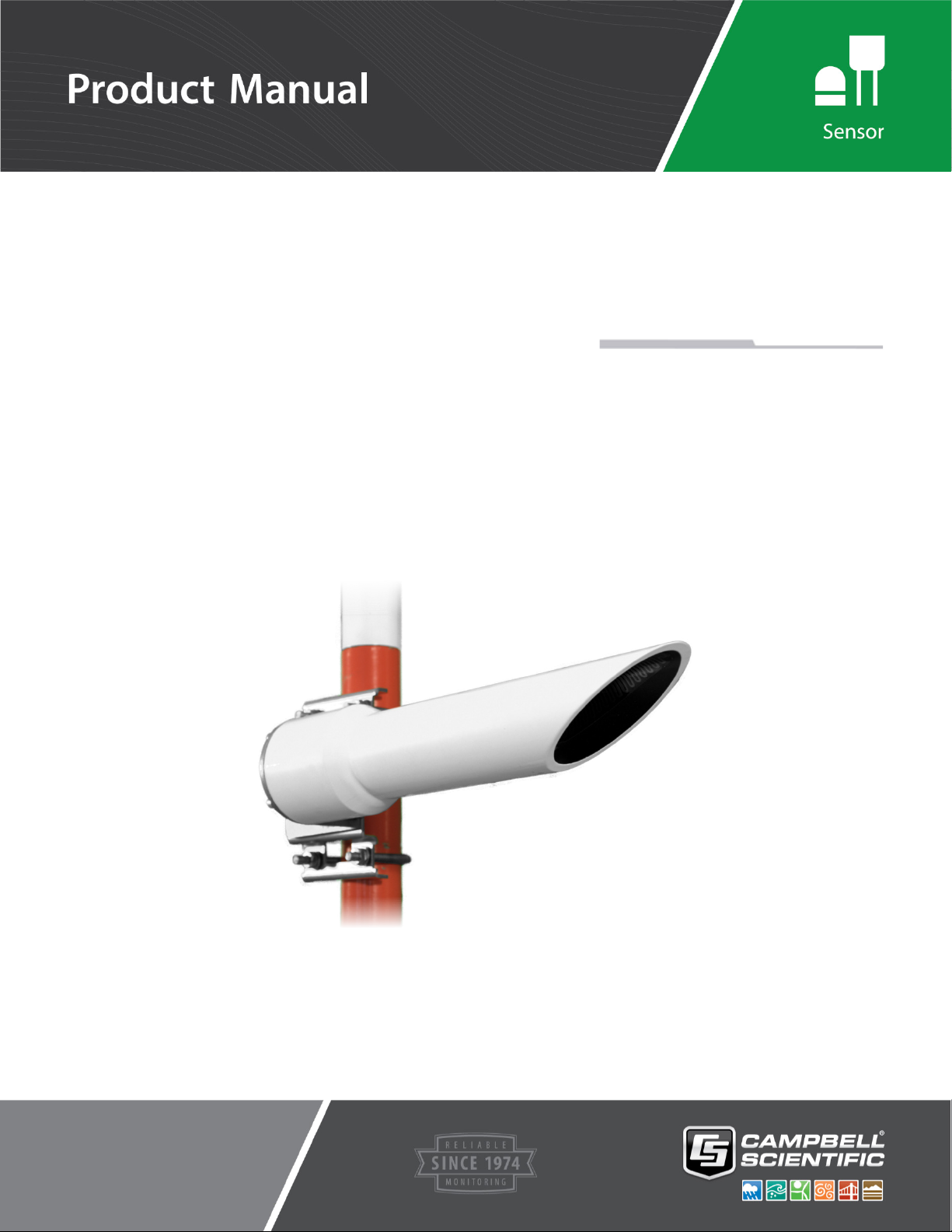
CS140
Background
Luminance Sensor
Revision:
Copyright ©
Campbell Scientific, Inc.
11/20
2013 – 2020

About this manual
Some useful conversion factors:
Area: 1 in
Length: 1 in. (inch) = 25.4 mm
2
(square inch) = 645 mm2
1 ft (foot) = 304.8 mm
1 yard = 0.914 m
1 mile = 1.609 km
Mass:
Pressure: 1 psi (lb/in
Volume: 1 UK pint = 568.3 ml
1 oz. (ounce) = 28.35 g
1 lb (pound weight) = 0.454 kg
2
) = 68.95 mb
1 UK gallon = 4.546 litres
1 US gallon = 3.785 litres
Recycling information
At the end of this product’s life it should not be put in commercial or domestic refuse
but sent for recycling. Any batteries contained within the product or used during the
products life should be removed from the product and also be sent to an appropriate
recycling facility.
Campbell Scientific Ltd can advise on the recycling of the equipment and in some cases
arrange collection and the correct disposal of it, although charges may apply for some
items or territories.
For further advice or support, please contact Campbell Scientific Ltd, or your local agent.
Campbell Scientific Ltd, Campbell Park, 80 Hathern Road, Shepshed, Loughborough, LE12 9GX, UK
Tel: +44 (0) 1509 601141 Fax: +44 (0) 1509 270924
Email: support@campbellsci.co.uk
www.campbellsci.co.uk

Contents
PDF viewers note: These page numbers refer to the printed version of this document. Use
the Adobe Acrobat® bookmarks tab for links to specific sections.
Section 1. General Information ...................................... 1
1.1 General Safety ............................................................................................ 1
1.2 Sensor Unit Safety ...................................................................................... 1
1.3 Recommended Tools .................................................................................. 1
Section 2. Product Overview ......................................... 2
2.1 Introduction ............................................................................................... 2
2.2 Specifications ............................................................................................ 3
2.2.1 Optical Specifications ..................................................................... 3
2.2.2 Electrical Specifications .................................................................. 3
2.2.3 Communications Specifications ...................................................... 3
2.2.4 Environmental Specifications ......................................................... 4
2.2.5 CS140CAL Calibrator Specifications ............................................. 4
Section 3. Mechanical Specifications ........................... 5
3.1 Dimensions ............................................................................................... 5
3.2 Weights ..................................................................................................... 5
Section 4. Installation ..................................................... 5
4.1 Location and Orientation .......................................................................... 5
4.2 Grounding ................................................................................................. 6
4.3 Mounting the CS140 ................................................................................. 6
4.4 Connectors ................................................................................................ 7
4.5 Wiring Using Supplied Campbell Scientific Cables ................................. 8
4.6 Maintenance cable .................................................................................... 9
4.7 Storage Information ................................................................................ 10
Section 5. Messages .................................................... 10
5.1 Message structure.................................................................................... 10
Section 6. Interface methods ....................................... 13
6.1 Command line/menu ............................................................................... 13
6.2 Configuring a PC for talking to the CS140 ............................................. 13
6.3 Definition of the variables that can be set by the user on the CS140
with the command line interface .......................................................... 14
6.4 Command line mode ............................................................................... 15
6.4.1 The SET Command....................................................................... 15
6.4.2 The SETNC Command ................................................................. 16
6.4.3 The GET Command ................................................................ ...... 16
6.4.4 The POLL command – Polling the CS140 .................................... 18
6.5 The CS140 menu system ................................................................ ......... 18
Section 7. Calibrating the CS140 ................................. 23
i

Section 8. Performing an OS update ........................... 25
Section 9. Maintenance ................................................ 27
9.1 General.................................................................................................... 27
9.2 Cleaning .................................................................................................. 27
Appendix
A. Example C code of the CCITT CRC .................... A-1
B. Example CRBasic programs .............................. B-1
Figures
2-1. CS140 Background Luminance sensor .................................................... 2
4-1. Mounting the CS140 onto a pole ............................................................. 6
4-2. Connector layout ..................................................................................... 7
4-3. Connector pin-outs .................................................................................. 8
4-4. Cable Connections ................................................................................... 9
4-5. CS140 Maintenance Cable ...................................................................... 9
7-1. CS140 Calibrator ................................................................................... 23
7-2. CS140 Calibrator Connections .............................................................. 24
8-1. CS140 DevConfig OS download instructions ....................................... 23
8-2. CS140 DevConfig screen when OS update is complete ........................ 23
ii

CS140 Background Luminance Sensor
WARNING
CAUTION
NOTE
CAUTION
1. General Information
1.1 General Safety
This manual provides important safety considerations for the installation,
operation and maintenance of the CS140. These safety considerations are
classified into three levels:
Warnings alert the installer or user to serious hazards.
Ignoring these warnings could result in injury or death
and/or irrevocable damage to the sensor unit.
Cautions warn of potential hazards. Ignoring these cautions
could result in the sensor being damaged and data being lost.
Notes highlight useful information in the installation, use and
maintenance of this product. These should be followed carefully in
order to gain the maximum benefit from the use of this product.
1.2 Sensor Unit Safety
The CS140 sensor has been checked for safety before leaving the factory and
contains no internally replaceable or modifiable parts.
Do not modify the CS140 unit. Such modifications will
lead to damage of the unit.
1.3 Recommended Tools
The following tools are recommended for installation:
10 mm open spanner/wrench (for grounding boss, must be open)
13 mm spanner/wrench
1
CS140 Background Luminance Sensor
2
2. Product Overview
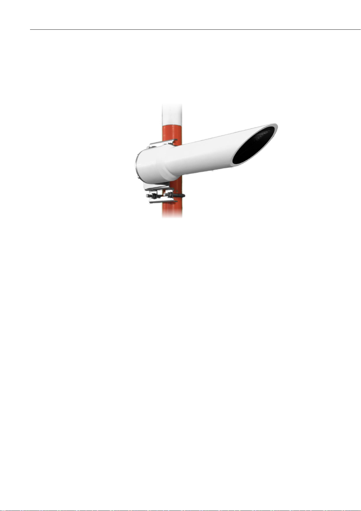
2.1 Introduction
Figure 2-1. CS140 Background Luminance sensor
The CS140 Background Luminance Sensor accurately measures background
luminance over a wide range from 0 cd/m2, to a maximum of 45,000 cd/m2.
It uses a photodiode with a spectral response close to the CIE human eye model and
removes any unwanted wavelengths via an inbuilt band-pass filter.
The CS140 features a fixed 6˚ field of view as specified by the FAA. For easy
installation the CS140 is simply mounted horizontally with the required 6˚ inclination
being built into the design. (Other angles are possible via the sensors mounting
bracket).
A heated hood will prevent ice and snow from building up, dew heaters will prevent
condensation on the glass window and a dirty window detection system measures
window contamination.
The design is undamaged when pointed directly at the sun allowing complete
flexibility in orientation and it has a rugged IP66 rated environmental enclosure that
protects it from the harshest conditions and will measure the atmosphere with high
stability and repeatability.

Instruction Manual
3
2.2 Specifications
2.2.1 Optical Specifications
Accuracy
±0.2 cd/m2 < 2 cd/m2, ±10% > 2 cd/m2
Field of view
6°
Spectral response
CIE 1931
Measurement range
0-45,000 cd/m2
Resolution
0.1 cd/m2
2.2.2 Electrical Specifications
Minimum Value
Nominal Value
Maximum value
Main power supply for DSP and dew heater
Power supply, DC only
9V
12V
30V
Current consumption sampling continuously
with dew heater active (at 12V)
5 mA
90 mA
7 mA
95 mA
9 mA
100 mA
Hood heater power supply
Hood heater voltage (AC or DC)
24V
30V
Hood heater power (at 24V AC or DC)
48W
55W
2.2.3 Communications Specifications
Serial setting 8N1
Supported data rates
1200 baud
2400 baud
9600 baud
19200 baud
38400 baud - default
57600 baud
115200 baud
Supported formats
RS-232 (full duplex, no hardware handshaking)
RS-485 (half duplex only)

CS140 Background Luminance Sensor
4
Signal voltage levels
Minimum
Value
Nominal
Value
Maximum
Value
RS-232 Communications
RS-232 input threshold Low
0.8V
1.5V
-
RS-232 input threshold High
-
2.0V
2.4V
RS-232 input absolute maximum
-15V
-
+15V
RS-232 input resistance
12kΩ - -
RS-232 output voltage low
- - 0.4V
RS-232 output voltage high (into 3KΩ)
4.4V - -
RS-485 Communications
RS-485 input threshold voltage
-0.2V
-
+0.2V
RS-485 output (Unloaded)
- - 5V
RS-485 output (Load 50Ω)
2V - -
Maximum voltage at any terminal
-7V
-
+7V
2.2.4 Environmental Specifications
Minimum Value
Nominal Value
Maximum value
Sensor temperature ranges
Operating temperature
-25°C
-
+60°C
Extended operating temperature
-40°C
+70°C
(1)
Storage temperature
-40°C
-
+85°C
Sensor humidity range
Operating humidity range
0%
-
100%
Sensor heater thresholds
Dew heater turn on
-
<35°C
-
Dew heater turn off
-
>40°C
-
Hood heater turn on
-
<5°C
-
Hood heater turn off
-
>15°C
-
(1) Extended temperature ranges are only guaranteed if the sensor has been tested by Campbell Scientific and verified over this
temperature range.
Ingress protection
IP66
2.2.5 CS140CAL Calibrator Specifications
A field calibration device, the CS140CAL, is available. Specifications as below.
Temperature range
0 – 40°C
Calibration value
4,500 cd/m2
Accuracy
+/- 6%
Ingress protection
IP52
Communication1
RS-232, 38400 bd
Dimensions (excluding cables)
72 mm long x 46 mm diameter
Weight
300 g
1
Connecting the CS140CAL to a CS140 forces communications to RS-232, 38400 bd and also forces the sensor ID to ‘0’.
Instruction Manual
5
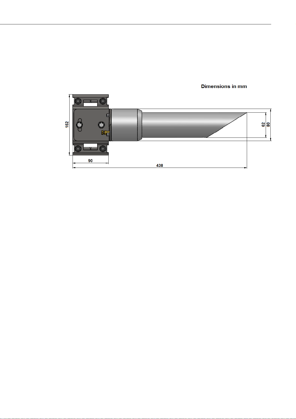
3. Mechanical Specifications
3.1 Dimensions
3.2 Weights
Sensor weight 2.4 kg
Shipping weight 3.5 kg
4. Installation
4.1 Location and Orientation
The CS140 measures environmental variables and is designed to be located in harsh
weather conditions. However there are a few considerations to take into account if
accurate and representative data from a site are to be obtained.
In order to reduce the service frequency with the unit, the CS140 should, if possible,
be placed away from sources of contamination. More regular maintenance will be
required when the instrument is placed in areas where contamination is unavoidable
or where measurements may be safety related.
The CS140 can be orientated in any direction required by local practice and it is not
damaged by sunlight shining directly into it. It should not be pointed at a source of
bright light that may be unrepresentative. Although of course its readings will not be
accurate in these circumstances. Note that with the sensor horizontal the centre of the
field of view is actually 6 degrees above horizontal. The mounting bracket allows
adjustment by +/- 12° if the mast is not vertical or if it is necessary to elevate the field
of view at an angle other than 6°.
CS140 Background Luminance Sensor
6
4.2 Grounding
The CS140 must be properly grounded by taking a ground wire with a minimum
cross sectional area of 6 mm2 and maximum length of 5 m from the brass grounding
lug at the rear of the unit to an adequate grounding point. The pole and foundations of
a pole mounted installation will provide some basic lightning protection and
protection against radio frequency interference and should also be correctly grounded.
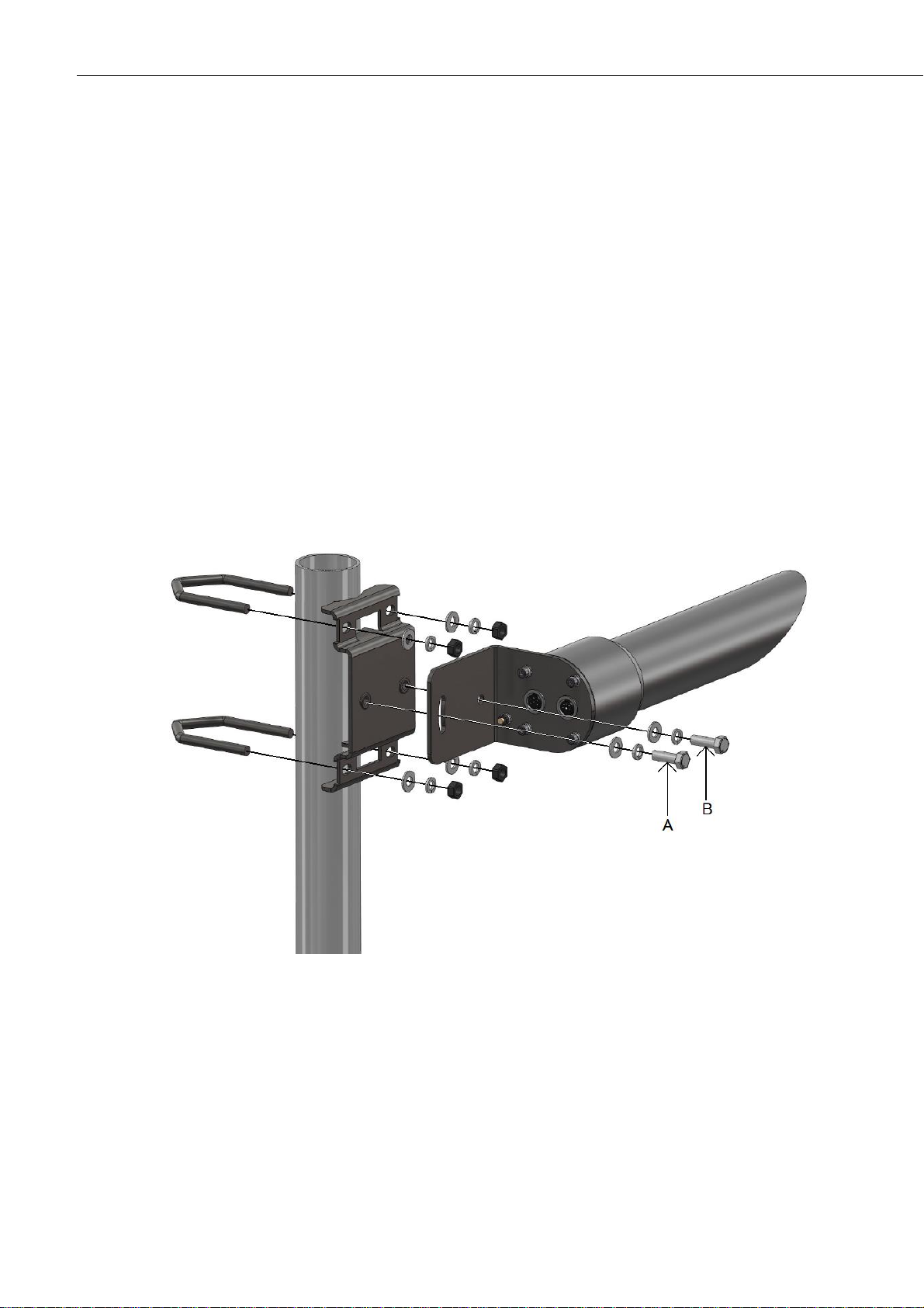
4.3 Mounting the CS140
A pole mounting kit is supplied with the CS140. This kit includes a mounting plate,
two V-bolts and suitable bolts for clamping the pole between the plate and brackets.
To mount the CS140 onto a pole:
1. The mounting plate is supplied ready fixed to the CS140. Offer up the plate to the
pole and present the brackets and bolts from the other side of the pole to fit into
the matching holes of the plate as shown in Figure 4-1.
Figure 4-1. Mounting the CS140 onto a pole
2. Clamp the pole between the plate and brackets by tightening using the nuts
provided.
The machine screws A and B in Figure 4-1 are used to level the CS140. Screw A is
used to lock the CS140 at the right elevation with screw B acting as a pivot. Usually
this will be with the hood horizontal which gives a field of view elevated by 6
degrees.
Instruction Manual
7
Take care not to overtighten the nuts on the bolts as it may be possible to distort and/or damage the brackets by doing so, and/or the nuts may seize up. Only tighten
the nuts to a degree necessary to hold the CS140 firmly in place.
Where the CS140 is to be mounted onto another type of mast, please refer to the
manual for that mast for mounting details.
Do not reposition, once fixings are tightened, by forcing the unit as this can cause
damage.
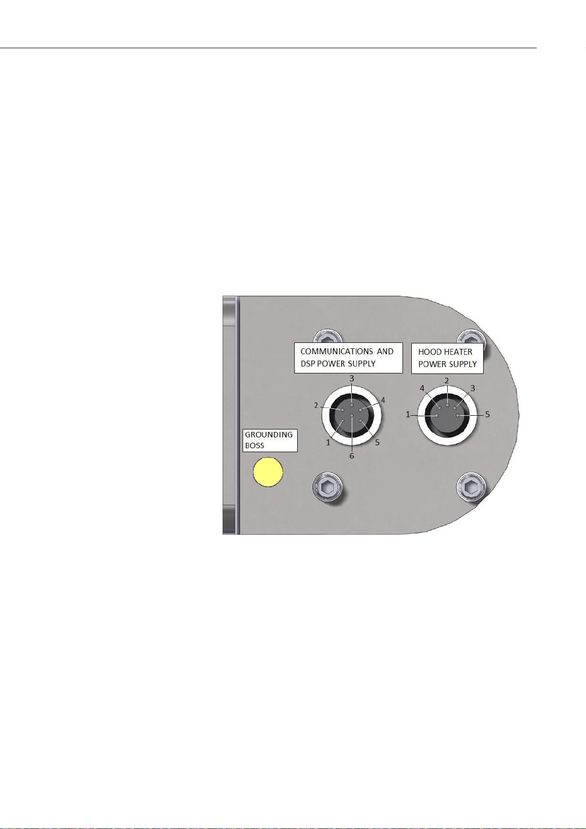
4.4 Connectors
The CS140 has two connectors. One is for communications and the sensor power
supply and one provides power to the hood heater.
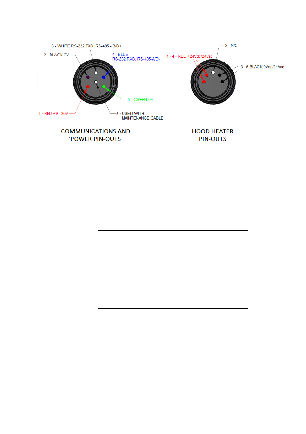
Figure 4-3 shows the pin-outs of the sockets viewed from outside. Colours shown are
the colours of the cores in the supplied cables.
Figure 4-2. Connector layout
CS140 Background Luminance Sensor
CAUTION
CAUTION
Figure 4-3. Connector pin-outs
4.5 Wiring Using Supplied Campbell Scientific Cables
Two cables are supplied, each 5 m long. One is for communications and the sensor
power supply, the other is for the hood heater.
If the power cable is incorrectly wired to the CS140 then
irrevocable damage can be done to the unit.
The communications cable is terminated at one end with a 9 pin D-connector (DB9).
The D-connector can be connected directly to a PC or data logger such as the
Campbell Scientific CR1000 using a suitable interconnecting cable such as the
SC110. If another type of connection is required then the D-connector can be easily
removed.
10 m is the longest length of cable recommended. In
particular additional RS-485 cable should be twisted pair.
Please contact Campbell Scientific if you wish to use a longer
length of cable.
8
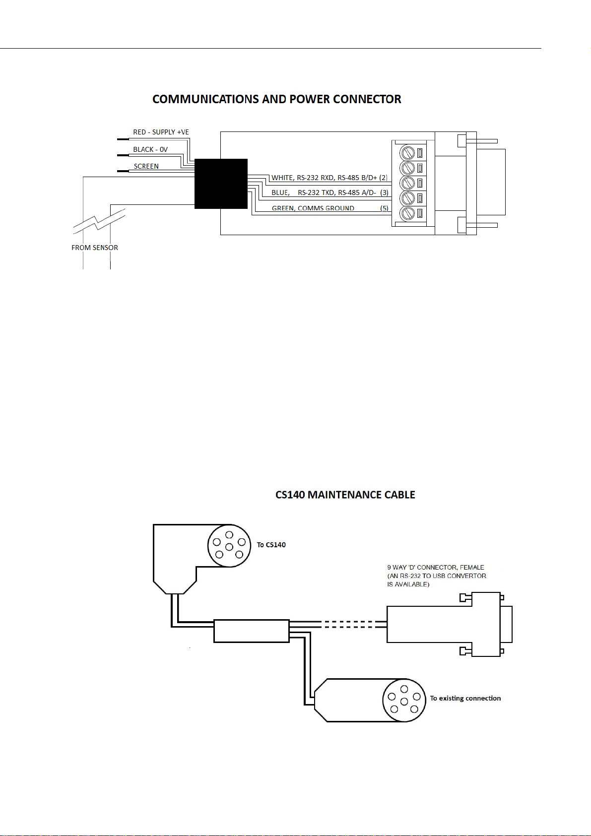
4.6 Maintenance cable
Instruction Manual
Figure 4-4. Cable Connections
A maintenance cable is available from Campbell Scientific that will force
communications to RS-232 38400 baud, and sensor id “0”.
The cable has connectors allowing it to be put in between the CS140 and the existing
connection and a 5 m flying lead with a 9-way D connector for RS-232
communication. The sensor will continue to draw power from the existing source.
When installed, the existing communication path is disconnected and communication
via the flying lead is forced to RS-232, 38400 bd with a sensor ID of “0”.
When it is removed and replaced with the cable previously used the baud rate and ID
will return to those previously set.
Figure 4-5. CS140 Maintenance Cable
9

CS140 Background Luminance Sensor
10
4.7 Storage Information
The CS140 should be stored between -40C to +85C in a dry place. The optics
should be protected from possible accidental damage.
5. Messages
5.1 Message structure
Basic Format
STX
Message ID Sensor ID System status Luminance Units Checksum
(CCITT) ETX
Carriage return Line feed
0x02 0 0 3 35833.7
1
4E7C
0x03
0x0D
0x0A
Example basic format output
Partial Format
STX
Message
ID
Sensor ID System status Message Interval Luminance Units User alarms Checksum
(CCITT) ETX
Carriage return Line feed
0x02
1 0 3
10
15732.2
1
0 0 0 0
1ED9
0x03
0x0D
0x0A
Example partial format output
Full Format (default)
STX
Message ID Sensor ID System status Message Interval Luminance Units
Averaging
Duration
User alarm System alarms Checksum
(CCITT) ETX
Carriage return Line feed
0x02
2 0 3
10
15292.4
1 1 0 0 0 0
1 0 3 0 0 0 0
0 0
F8DA
0x03
0x0D
0x0A
0 0 3 35833.7 1 4E7C
1 0 3 10 15732.0 1 0 0 0 0 1ED9

Instruction Manual
11
Example full format output
Message ID break down
ID
Definition
0
Basic format. Contains only luminance and system information
1
Partial format. Contains user alarm outputs
2
Full format. Contains all system alarms codes
Sensor ID break down
ID
Definition
0-9
Unit number defined by the user to aid identification of data. “0” by default.
Useful for RS-485 networks. Operates as an address in RS-485 mode
System status break down
(1),(2)
Status level
Definition
0
No fault
1
Possible degraded performance
2
Degraded performance
3
Maintenance required
(1) System status break down reflects the highest level of severity of any active alarm.
(2) Refer to the individual alarms (below) for details of the response times of the alarms.
Message interval
Time
Definition
1-3600
The amount of time, in seconds, between outputs in continuous mode
Luminance break down
ID
Definition
0-50,000
Current luminance being detected by the sensor. The maximum luminance level
reported by the sensor can be defined by the user via the menu system.
Visibility units break down
ID
Definition
1
Cd/m2
2
fL
Averaging duration break down
ID
Definition
1
One minute average
10
Ten minute average
2 0 3 10 15292.4 1 1 0 0 0 0 1 0 3 0 0 0 0 0 0 F8DA

CS140 Background Luminance Sensor
12
User and system alarms break down
Alarm
Range
System
status
Definition
User Alarm
0-1
1
0 = User alarm not active
1 = User alarm active
Spare
Reserved for future use
Spare
Reserved for future use
Spare
Reserved for future use
Window
contaminated
(1)
0-3
0
1
3
0 = OK. The reported attenuation is below 10%.
1 or 2 = Reported dirt level is over 10%
3 = High level of returned dirty signal. This could be either a
blocked sensor or a broken dirty window system.
Photo diode
temperature
0-3
0
1
1
3
0 = Temperature is within operating conditions.
1 = Too low. Less than -40°C.
2 = Too high. Over 70°C.
3 = Sensor fault (No sensor detected or below -49°C)
Hood
temperature
0-3
0
1
1
2
0 = Temperature is within operating conditions.
1 = Too low. Less than -45°C.
2 = Too high. Over 70°C.
3 = Sensor fault (No sensor detected or below -49°C)
Detector DC
saturation
level
(2)
0-1
0
2
The amount of background light as seen by the detector hood.
0 = Within limits
1 = Saturated. The CS140 is experiencing direct light levels
that are saturating the photo diode
Signature error
0-1
3
0 = Signature of entire flash was checked and matches the
stored version
1 = Signature does not match previous readings
Flash write
error
0-1
3
0 = No errors
1 = One or more errors writing user variables to flash
occurred
Flash read error
0-1
3
0 = No errors
1 = One or more errors reading user variables from flash
occurred
Internal
voltages
0-1
3
0 = No errors
1 = One or more errors writing user variables to flash
occurred
Spare
Reserved for future use
(1) With firmware version 9 onwards, this alarm flag will not increase in level until the dirt
detector has been above the "dirt" threshold continuously for 15 minutes or more. This is
to prevent transient setting of the flag which might be caused by reflections, insects etc.
(2) With firmware version 9 onwards, this alarm flag will not change to level 1 unless the
sensor has been continuously saturated for 60 mins or more. This is to avoid false alarms
if the sun shines directly into the sensor.

Instruction Manual
13
6. Interface methods
6.1 Command line/menu
The CS140 can be setup and controlled in one of two ways.
The first method is by using the command line interface where discrete commands are
sent without response from the sensor. This would be the preferred method of setting
up a CS140 if it was connected to a logger for instance. The configuration setting
commands can be sent via a logger to the CS140 removing the need for a local PC to
set up the unit.
The second method is by using the simple menu interface built into the CS140
communicating via RS-232 or RS-485, using a terminal emulator program. This menu
system gives access to the more common settings.
6.2 Configuring a PC for talking to the CS140
Described below is the procedure for setting up communications using a terminal
emulator program. The terminal emulators built into many Campbell Scientific
software products can also be used.
The following settings should then be used by default:
Bits per second: 38400
Data bits: 8
Parity: none
Stop bits: 1
Flow control: none
Ensure that if the baud rate of the unit has been adjusted and then the corresponding
bits per second value is entered in the port settings of the terminal emulator. The
CS140 should now be ready to accept commands.

CS140 Background Luminance Sensor
14
6.3 Definition of the variables that can be set by the user on the CS140 with the command line interface
The command line interface can access all the user configurable variables listed
below:
ID
Name
Range
Description
Factory
default
1
Sensor ID
0-9
Separate ID used as an identifier for a particular
CS140 on a network.
0
2
Serial port protocol
0-1
Selects the physical serial interface
0 = RS-232 mode
1 = RS-485 mode
0
3
Serial Baud Rate
0-6
Baud rate for the main RS-232/RS-485 interface
0 = 115200 bps
1 = 57600 bps
2 = 38400 bps
3 = 19200 bps
4 = 9600 bps
5 = 2400 bps
6 = 1200 bps
2
4
Serial Number
(Read only so not used)
0-32000
Internal serial number for the CS140.
(Read only)
-
5
Luminance Units
0-1
Units the CS140s luminance value is reported in.
0 = Candela per metres square (cd/m2)
1 = Foot lamberts (fL)
0
6
Message Interval
1-3600
Interval in seconds between outputs in continuous
mode. This value has no effect if polled mode has
been selected in ‘Measurement mode’
60
7
Measurement mode
0-1
Selects polled or continuous modes.
In continuous mode the sensor will output a string
in the format as set by ‘Message Format’ at
regular intervals as defined by ‘Continuous
Interval’.
0 = Continuous mode
1 = Polled mode
0
8
Message Format
0-2
Level of detail outputted by polled or continuous
modes
0 = Basic 1 = Partial 2 = Full
2
9
Sample timing
1-60
Not currently implemented
1
10
Averaging period
1 or 10
The period of time that the luminance value
should be averaged over. Either one minute or ten.
1
11
Dew heater override
0-1
0 = Allow the CS140 to automatically control the
dew heater
1 = Turn the dew heater off
0
12
Hood heater override
(1)
0-1
0 = Allow the CS140 to automatically control the
hood heater
1 = Turn the hood heater off
0
13
Dirty window
compensation
0-1
0 = No compensation applied
1 = Compensation for dirt on window applied.
The CS140 will compensate for up to 10% signal
loss due to dirt on the window.
0
14
Use CRC
0-1
0 = Disable command line CRC checking
(2)
1 = Enable command line CRC checking
Note: this does not affect communications via
DevConfig or terminal emulator.

Instruction Manual
15
15
Power Supply Unit
(PSU) voltage level
shutdown
9-30
PSU Input voltage level below which the CS140
will enter low power mode. This is usually used to
protect batteries. (Note: The CS140 will start to
shut itself down via hardware at about 8 volts)
9.0
16
Enable alarm
0-1
1 = alarm on
0
17
Alarm high/low
0-1
Sets whether the alarm is triggered by a luminance
higher or lower than the alarm level
0
18
Alarm level
0-45,000
In cd/m2
10,000
(1) Hood heater override needs to be set to `1’ (off) when the hood heater has no power
connected. This will save power as the relay is not enabled at low temperatures in this mode.
(2) If disabled the sensor does not check the validity of received data against the checksum
sent. It is, however, recommended that checksum checking is enabled to remove any chance of
the CS140 being configured incorrectly by accident.
6.4 Command line mode
The command line interface is broken down into three major commands. These are
GET, SET and POLL. The GET command is used to request all current user settable
values from the CS140. The SET commands sets user settable values and the POLL
command is used to request the current visibility and/or alarm conditions from the
sensor.
The CS140 can be configured to expect any commands sent to it to include a valid
checksum. For simple commands, e.g. GET and POLL, fixed value checksums can be
used (see the example programs). For more complex SET commands the checksum
needs to be calculated (see Appendix B). The use of the checksum is disabled by
default. It is recommended that the checksum functionality is enabled where possible,
especially when long cable runs are used, or in electronically noisy environments.
6.4.1 The SET command
The set command is used to configure the CS140 via the command line. The SET
command is a single space delimited string that can be sent from any data logger or
PC equipped with an RS-232 or RS-485 port. The SET command accesses identical
settings within the CS140. This command is used to change the default power up state
of the sensor. The Set command is echoed back.
Example of a SET command and the echoed reply

CS140 Background Luminance Sensor
16
SET transmitted/echoed data
Example
Description
0x02
(1)
STX
:
Delimiting character
SET
SET
:
Delimiting character
0
Address based on Sensor ID
:
Delimiting character
0
Sensor ID
2
Serial port protocol
0
Serial Baud Rate
1000
Sensor serial number (only in echoed reply)
0
Luminance Units
10
Continuous mode output interval
1
Polling Or Continuous modes
2
Message Format (Basic/Partial/Full)
1
Averaging Period
1
Sample timing
0
Dew heater override
0
Hood heater override
0
Dirty window compensation
1
CRC checking on received commands
9.5
Sensor power down voltage
0
Enable alarm
0
Alarm high/low
10 000
Alarm level
:
Delimiting character
0146
Checksum (use the valid CCITT checksum)
:
Delimiting character
0x03
(1)
ETX
0x0D
(1)
Carriage return
(1) These values are shown in hexadecimal format not ASCII.
6.4.2 The SETNC Command
The format of the SETNC command is the same as the SET command except it starts
with SETNC. The only functional difference is that the SETNC command does not
commit the values set into flash memory. This means that the next time the CS140 is
power cycled it will revert back to its previous settings. This command should be
used when a setting in the sensor is changed regularly, e.g. heater functions, as this
command avoids the risk of wearing out the flash storage memory. Note: this includes
communication data rates as well.
6.4.3 The GET Command
The GET command retrieves settings data from the CS140, including message format
data and user alarm settings amongst others. This command does not retrieve
visibility or environmental information from the CS140. To retrieve visibility data
refer to the POLL command.

Instruction Manual
17
The GET command
GET transmitted data
Example
Description
0x02
(1)
STX
GET
GET
:
Delimiting character
0
Address based on Sensor ID
:
Delimiting character
0
Reserved for future use, zero default
:
Delimiting character
2C67
Checksum
:
Delimiting character
0x03
(1)
ETX
0x0D
(1)
Carriage return
(1) These values are shown in hexadecimal format not ASCII.
Example of a GET request
GET : 0 : 0 : 2C67 :
Example data returned by the GET command
GET returned data
Example
Description
0x02
(1)
STX
0
Sensor ID
0
Serial port protocol
2
Serial Baud Rate
1000
Sensor serial number (read only)
0
Luminance Units
60
Continuous mode output interval
0
Polling Or Continuous modes
2
Message Format (Basic/Partial/Full)
1
Averaging Period
1
Sample timing
0
Dew heater override
0
Hood heater override
0
Dirty window compensation
1
CRC checking on received commands
7.0
Sensor power down voltage
0
Enable alarm
0
Alarm high/low
10000
Alarm level

CS140 Background Luminance Sensor
18
:
Delimiting character
626C
Checksum
:
Delimiting character
0x04
(1)
EOT
0x0D
(1)
Carriage return
0x0A
Line feed
(1) These values are shown in hexadecimal format not ASCII.
6.4.4 The POLL command – Polling the CS140
The POLL command requests the current visibility and/or alarm conditions from the
CS140. The output format of this command depends on how the CS140 is configured
using the SET command or the menu interfaces.
Example of a POLL request with returned message
The POLL request
POLL transmitted data
Example
Description
0x02
(1)
STX
POLL
POLL
:
Delimiting character
0
Address based on Sensor ID
:
Delimiting character
0
Reserved for future use, zero default
:
Delimiting character
3A3B
Checksum
:
Delimiting character
0x03
(1)
ETX
0x0D
(1)
Carriage return
(1) These values are shown in hexadecimal format not ASCII.
6.5 The CS140 menu system
When connected to the CS140 the user can enter the menu system by typing ‘open id’
into their terminal program then pressing the return key on their keyboard. The id
corresponds to the sensor ID number. The Sensor ID number can be in the range of 0
to 9. The factory default is 0.
The ‘open 0’ command is not normally echoed.
The terminal menu only gives access to more common settings.
NOTE
POLL:0:0:3A3B:
2 0 0 60 22.9 1 1 0 0 0 0 0 0 0 0 0 0 0 0 0 5EC7

Instruction Manual
19
The following text will now be displayed:
The displayed options are accessed simply by typing the corresponding number then
pressing return. No changes will take effect until you `save and exit’. The exception
to this is the calibration menu, but you will be informed before any changes are made.
The displayed options are accessed simply by typing the corresponding number then
pressing return. No changes will take effect until you `Exit and Save’. The exception
to this is the calibration menu, but you will be informed before any changes are made.
Typing ‘1’ opens the message menu containing settings relating to the CS140’s
outputs.
Menu 1: The message output menu
For example typing ‘2’ will toggle the units through the options cd/m2 and fL and
typing ‘4’ will allow the message interval to be entered.
Option (2) allows the User Alarms to be set, again by toggling through options or
changing values.
It also allows the measurement range to be set. Upper and lower limits can be set
individually or the CS140 can be set to report between FAA limits
(6.85-41115.0 cd/m2, 2-12000fL or UK CAA limits (5-35000.0 cd/m2).
CS140 MESSAGE - MENU 1
ID 0
S/N 1009
(1) Toggle message format: FULL
(2) Toggle units: cd/m2
(3) Toggle polled or continuous mode:CONTINUOUS
(4) Set continuous mode output interval: 6 second(s)
(5) Toggle output averaging period: 1 minute(s)
(6) Sampling interval: 1 second(s)
(9) Refresh
(0) Return to main menu
WELCOME TO THE CAMPBELL SCIENTIFIC LTD CS140 SETUP MENU
ID 0
S/N 1009
(1) Message output menu
(2) User alarm menu
(3) Communications setup
(4) System information
(5) System configuration
(6) Calibration
(9) Exit and save
(0) Exit and don't save

CS140 Background Luminance Sensor
20
Menu 2: The user alarm menu
Option (3) gives the communications menu. This is used to set baud rates and the
mode of operation (RS-232/RS-485).
No change will take effect until you `exit and save’.
Menu 3: The communications menu
CS140 COMMUNICATIONS - MENU 3
ID 0
S/N 1009
(1) Set sensor ID
(2) Set RS232/RS485 baud rate: 38400
(3) Toggle RS232/RS485 modes: RS232
(9) Refresh
(0) Return to main menu
->
NOTE
CS140 ALARM AND LIMIT - MENU 2
ID 0
S/N 1009
(1) Toggle user alarm one: DISABLED
(2) Toggle alarm one threshold: LESS THAN
(3) Set new user alarm one activation point:
10000 cd/m2
(4) Set upper output limit: 45000 cd/m2
(5) Set lower output limit: 5 cd/m2
(6) Set to FAA limits
(7) Set to CAA limits
(9) Refresh
(0) Return to main menu
->

Instruction Manual
21
Option (4) gives the systems information menu containing useful information such as
temperature and system alarms.
Menu 4: The system information menu
CS140 INFORMATION - MENU 4
ID 0
S/N 1009
OS version: 7644-07
Alarm Value
- One Minute Luminance value: - 3100.0
- Overall system status: 0 No faults
- Detector dirty window alarm: 0 0%
- Sensor internal temperature: 0 28.0
- Hood heater temperature: 0 22.7
- CS140 Rig Constant: - 100
- CS140 Reference Value: - 100.00
- Calibration value Fac offset: - -33.00
- Calibration value Fac scale: - 30.00
- User Reference Value, cd/m2: - 4500.00
- User calibration value offset: - 19.66
- User calibration value scale: - 332.4
- Signature fault: 0 -
- Flash write errors: 0 0
- Flash read errors: 0 0
- Supply voltage: <9.0V 11.5V
- Aux supply voltages: +5V=5.0 +3V=3.0
(8) Get debug
(9) Refresh
(0) Return to main menu
->
If the dirty window alarm is set it is recommended you follow the cleaning section of
this manual (Section 8.2).
If there is a flash error or signature error it is recommended that you contact Campbell
Scientific.
The aux supply voltages are internal 5 volt and 3 volt supplies. They should be
between 4.5 and 5.5 and 2.7 and 3.3 volts respectively.
Menu option (5) allows configuration of heaters, window compensation, CRC
Checking and the power down voltage.
CS140 CONFIGURATION - MENU 5
ID 0
S/N 1009
(1) Toggle dew heater override: AUTOMATIC
(2) Toggle hood heater override: AUTOMATIC
(3) Toggle dirty window compensation: NO COMPENSATION
(4) Toggle command line CRC Checking: DO NOT CHECK
(5) Sensor power down voltage: 9.0V
(9) Refresh
(0) Return to main menu
->

CS140 Background Luminance Sensor
22
Menu option (6) allows calibration of the CS140 using an optional CS140CAL
calibration device.
It also allows the user to reset the CS140 to factory default values.
CS140 CONFIGURATION - MENU 6
ID 0
S/N 1004
(1) Perform a user calibration
(2) Reset the user calibration to factory values
(9) Refresh
(0) Return to main menu
->
To perform a calibration chose option (1). See section 7.
Once a calibration is finished changes are immediate, but factory
calibrations can be restored if needed using Option `(2)’ in the
calibration menu.
CS140 CALIBRATION - SUB 1
Are you sure you want to reset to factory defaults?
This will cause the sensor to reset.
Type 1234 followed by return to confirm, or anything
else to exit.
->1234
Menu items 9 and 0:
These exit the menu system with or without saving the changes made.
NOTE

Instruction Manual
23
7. Calibrating the CS140
The CS140 can be checked and adjusted using the optional CS140CAL calibrator.
The calibration must be run using the onboard menu system. If you have Campbell
Scientific’s Device Configuration program (DevConfig) a terminal emulation screen
is provided in the CS140 screens to let you access this function. To perform the
calibration you will need a CS140CAL calibrator and a computer with a compatible
USB port.
The CS140CAL is sealed to IP52 and will generate a test light level of 4,500 cd/m2
accurate to +/-6% over a temperature range of 0 – 40°C.
It is recommended to clean the window before calibrating the CS140.
The system is self-regulating. However it is recommended that the CS140 is
calibrated at least every two years.
The calibration is performed from menu item 6 on the main terminal screen.
Once you have selected menu item 6 you will be presented with the following screen.
Select option 1 to start the calibration.
At this point the calibration device and cable should be installed as shown in Figures
7-1 and 7-2. Connecting the calibrator switches the CS140 to communication at
38400 bd with a sensor ID of ‘0’. This will happen whatever the previous setting or
whether the CS140 was set to RS-232 or RS-485.
Figure 7-1. CS140 Calibrator
CS140 CONFIGURATION - MENU 6
ID 0
S/N 1004
(1) Perform a user calibration
(2) Reset the user calibration to factory values
(9) Refresh
(0) Return to main menu

CS140 Background Luminance Sensor
24
Figure 7-2. CS140 Calibrator Connections
The CS140 menu structure will still be available while the calibrator is connected.
You will then be asked to confirm that you would like to perform a calibration.
Once you have entered yes at this point you will not be able to exit until the test is
complete. However, power cycling the unit at this point will have no adverse effect
on the sensor.
Once you have started the tests you will be asked for the CS140CAL luminance value
with a confirmation at each step giving you the chance to correct typing mistakes. The
luminance value will be 4500.0 for CS140CAL calibrators.
When asked for confirmation you do not need to press return after you type
‘y’.
This part of the test will take approximately two minutes. Every ten seconds a dot
should appear indicating that the test is progressing as normal.
NOTE
Input the CS140CAL luminance value (cd/m2) -> 4500.0
Is 4500.0 correct? (Y/N)?
Y
Place the CS140CAL into the hood.
Ensure the CS140CAL is turned off, then press any
key.
H
Starting dark level calibration.............
Dark level test complete.
Do you want to perform a calibration Y/N?

Instruction Manual
25
This part of the test will take approximately two minutes. Every ten seconds a dot
should appear indicating that the test is progressing as normal.
The CS140 will then ask you to turn on the CS140CAL.
Once confirmed the light level calibration will begin.
Once the light level calibration has been completed the new calibration constants will
be saved automatically. All calibration constants including both the user and the
factory setting can be viewed from menu item (4). from the main menu once the test
is completed.
8. Performing an OS update
Operating system updates for the CS140 background luminance sensor are performed
using Campbell Scientifics Device Configuration Utility (DevConfig) software. This
is available as a free download from the Campbell Scientific website. Please refer to
the help built into the DevConfig software for full instructions on how to update the
CS140.
To use DevConfig to carry out an OS change requires RS-232
communication. However, if a sensor is set to communicate by RS-485
it is not necessary to change this in the sensor.
Connect a PC or laptop with DevConfig running to the sensor with RS232 communications. Run DevConfig to the stage shown in Figure 8-1.
Then turn on the sensors power supply. The update will then take place
through RS-232. The sensor will however remain in RS-485 mode
afterwards.
Figures 8-1 and 8-2 show the procedure using DevConfig.
NOTE
Turn the CS140CAL on.
Press any key once this is done.
Starting light level calibration. (This will take
5-6 minutes).....................................
Saving user calibration settings.
Calibration is now complete. You may remove the
CS140CAL at any time.
CS140CAL Val:4500.0 Offset:20.33 Scale:332.0
Press any key to exit.

CS140 Background Luminance Sensor
26
Figure 8-1. CS140 DevConfig OS download instructions
Figure 8-2. CS140 DevConfig screen when OS update is complete

Instruction Manual
27
9. Maintenance
9.1 General
The CS140 is a robust weather resistant instrument and there is no need for routine
maintenance other than cleaning. The instrument performance is monitored and any
potential problems are covered by error messages. Other maintenance is carried out
by return to Campbell Scientific.
9.2 Cleaning
The CS140 window will require cleaning from time to time. The frequency of
required cleaning depends on the ex posure of the instrument to contaminants such as
salt and dust. This will vary depending on the site location. The CS140 is capable of
self-diagnosing a dirty window and will indicate in its output when the window is
contaminated.
In any case we suggest six monthly intervals for locations not prone to contaminants
and monthly intervals for those prone to contamination (coastal, roadside or airport
use). In some cases more frequent cleaning may be required where there are high
levels of contaminants and high dependency on the instrument output.
If the window requires cleaning, it is very important that only a
proper lens cloth or lens tissue is used. The use of inappropriate
materials to clean the window can permanently damage or
reduce the effectiveness of the window leading to errors in
measurement of precipitation and visibility.
It is advisable to use an air duster to blow any loose dust and dirt from the window as
a first step. Using a lint free lens cloth or lens tissue impregnated with a small amount
of isopropyl alcohol solvent clean the surface by dragging the cloth across it being
careful not to apply excessive pressure.
Excessive pressure may lead to some types of contaminant scratching the window
surface. Over time such scratches can lead to reduced sensitivity.
CAUTION

Appendix A. Example C code of the CCITT CRC
The code below is provided as an example for programmers implementing their own
code to communicate with the sensor. Users using Campbell loggers can use the
checksum command in CRBasic to generate a CCITT checksum.
Command: Checksum/ChkSumString,1,0).
The checksum includes all characters after the STX and before the space preceding the
checksum.
The SET and SETNC commands also exclude the two delimiting `:’ characters, one on
each side of the checksum itself.
//---------------------------------------------------------------
------------// Creates a CCITT CRC16 checksum seeded with 0x0000 (XModem
style) using a
// fast non table based algorithm.
// Pass in the data to convert into a CRC in the form of a NULL
terminated
// character array (a string).
// Returns the CRC in the form of an unsigned 16 bit integer
value
// Note: This algorithm has only been tested on a native 16-bit
processor with
// a hardware barrel shifter
// All integers are 16-bits long
//---------------------------------------------------------------
------------unsigned int CRC_CCITT(char LineOfData[]){
unsigned int crc; // returned CRC value
unsigned int i; // counter
crc = 0x0000;
// create a check sum for the incoming data
for(i=0;i < strlen(LineOfData); i++){
unsigned crc_new = (unsigned char)(crc >> 8) | (crc << 8);
crc_new ^= LineOfData[i];
crc_new ^= (unsigned char)(crc_new & 0xff) >> 4;
crc_new ^= crc_new << 12;
crc_new ^= (crc_new & 0xff) << 5;
crc = crc_new;
}
return(crc);
}
A-1

Appendix B. Example CRBasic programs
B.1 Example CRBasic POLL program
'------------------------------------------------------------------------------' CS140 Luminance
'
' Program to test the POLL command part of the command line interface on the
CS140
' Logger:CR1000
'
' Example polling outputs
' POLL:0:0:3A3B:
' POLL:1:0:0D0B:
' POLL:2:0:545B:
' POLL:3:0:636B:
' POLL:4:0:E6FB:
' POLL:5:0:D1CB:
' POLL:6:0:889B:
' POLL:7:0:BFAB:
' POLL:8:0:939A:
' POLL:9:0:A4AA:
'-------------------------------------------------------------------------------
Public OutString As String * 40 ' Outgoing sting
Dim CheckVal As Long ' Checksum value
Public InString As String * 200 ' Incomming string
Dim TempString As String * 16
'Main Program
BeginProg
' open port to the Luminance sensor
SerialOpen (Com1,38400,3,0,10000)
' Send request for information once every 10 seconds
Scan (10,Sec,0,0)
' Create the POLL string going out to the CS140
TempString = "POLL:0:0"
CheckVal = CheckSum (TempString,1,0) ' Use the CCITT CRC16 checksum
OutString = CHR(2) + TempString + ":" + FormatLong (CheckVal,"%04X") +
":" + CHR(3) + CHR(13) + CHR(10)
SerialOut (Com1,OutString,"",0,100) ' Send POLL request to the CS140
Delay (1,1,Sec)
SerialIn (InString,Com1,100,0,1000) ' Grab retuned data from the POLL
command
NextScan
EndProg
B-1

Appendix B. Example CRBasic programs
B.2 Example CRBasic SET program
'------------------------------------------------------------------------------' CS140 Luminance
'
' Program to test the SET command part of the command line interface on the
CS140
' Do not run this script for extended periods of time (days!) as it writes
' to flash over and over and will eventually wear the flash out
' Logger:CR1000
'-------------------------------------------------------------------------------
Public InString As String * 200
Public TempString As String *100
' Variables for the SET command subroutine
Dim CS140CArray(21) As String * 6 ' CS140 Command Array
'------------------------------------------------------' This function creates a SET command string for the
' CS140 Luminance sensor. Including all delimiting
' characters and checksums
' then returns the string in "CS140CommandString"
' Array variable order is as follows:
' 1. Sensor ID
' 2. RS232 or RS485 serial communications enabled
' 3. Serial BaudRate
' 4. Serial number (Read only so not used)
' 5. Lumiance Units
' 6. Continuous mode output interval
' 7. Polling Or Continuous modes
' 8. Message Format (Basic/Partial/Full)
' 9. Sample timing
' 10. Averaging Period
' 11. Dew heater override
' 12. Hood Heater override
' 13. Dirty window compensation
' 14. Use CRC on SET, GET and POLL commands
' 15. PSU voltage level shutdown
' 16. User Alarm 1
' 17. User Alarm 1 Active
' 18. User Alarm 1 Activate Level
Function CS140_SETCommand As String *100
Dim TempStringFunc As String * 100
Dim CS140CommandString As String * 100
Dim i As Long
Dim CheckVal As Long
' Create a string containing the values going out to the CS140
TempStringFunc = "SET:0:"
For i = 1 To 18
TempStringFunc = TempStringFunc + CS140CArray(i) + " "
Next
' Create a check sum of the values going out
CheckVal = CheckSum (TempStringFunc,1,0) ' Use the CCITT CRC16
checksum
B-2

Appendix B. Example CRBasic programs
' Create final string going out to CS140 including start characters and end
characters
CS140CommandString = CHR(2) + TempStringFunc + ":" + FormatLong
(CheckVal,"%04X") + ":" + CHR(3) + CHR(13) + CHR(10)
'CS140CommandString = CHR(2) + TempStringFunc + CHR(3) + CHR(13) +
CHR(10) ' Use this line if no checksum is desired
Return(CS140CommandString)
EndFunction
'-------------------------------------------------------
'Main Program
BeginProg
' open port to the Luminance sensor using Com1
SerialOpen (Com1,38400,3,0,10000)
' Note: Change the following array variable to suit your own application
' load example/dummy values into the array
CS140CArray(1) = 0 ' Set ID to 0
CS140CArray(2) = 0 ' Serial communications to RS232 mode
CS140CArray(3) = 2 ' Baudrate to 38400
CS140CArray(4) = 0 ' The serial number is read only so this is a place holder
CS140CArray(5) = 0 ' Report in cd/m2
CS140CArray(6) = 10 ' Set the output interval to every 10 seconds
CS140CArray(7) = 1 ' Set POLLED output mode
CS140CArray(8) = 2 ' Full output message
CS140CArray(9) = 1 ' Sample once every second
CS140CArray(10) = 1 ' Average output over 1 minute
CS140CArray(11) = 0 ' Dew heater in automatic mode
CS140CArray(12) = 0 ' Hood heater in automatic mode
CS140CArray(13) = 0 ' Output not compensated by window contamination
level
CS140CArray(14) = 1 ' Check the CRC (Applied after this command)
CS140CArray(15) = 9.5 ' Shut down if supply is below 9.5V
CS140CArray(16) = 0 ' User alarm 1 not active
CS140CArray(17) = 0 ' User alarm 1 activates if less than activate level
CS140CArray(18) = 10000 ' User alarm 1 activate level
' Send information once every 10 seconds
Scan (10,Sec,0,0)
TempString = CS140_SETCommand() ' Create the outgoing string
SerialOut (Com1,TempString,"",0,100) ' Send SET command to the CS140
Delay (1,1,Sec)
SerialIn (InString,Com1,100,0,1000) ' Grab retuned data from the CS140
' Returned data is identical to the
' data a GET command would return
NextScan
EndProg
B-3

Appendix B. Example CRBasic programs
B.3 Example CRBasic SETNC program
'------------------------------------------------------------------------------' CS140 Luminance
'
' Program to test the SETNC command part of the command line interface on the
CS140
' Logger:CR1000
'-------------------------------------------------------------------------------
Public InString As String * 200
Public TempString As String *100
' Variables for the SET command subroutine
Dim CS140CArray(21) As String * 6 ' CS140 Command Array
'------------------------------------------------------' This function creates a SETNC command string for the
' CS140 Luminance sensor. Including all delimiting
' characters and checksums
' then returns the string in "CS140CommandString"
' Array variable order is as follows:
' 1. Sensor ID
' 2. RS232 or RS485 serial communications enabled
' 3. Serial BaudRate
' 4. Serial number (Read only so not used)
' 5. Lumiance Units
' 6. Continuous mode output interval
' 7. Polling Or Continuous modes
' 8. Message Format (Basic/Partial/Full)
' 9. Sample timing
' 10. Averaging Period
' 11. Dew heater override
' 12. Hood Heater override
' 13. Dirty window compensation
' 14. Use CRC on SET, GET and POLL commands
' 15. PSU voltage level shutdown
' 16. User Alarm 1
' 17. User Alarm 1 Active
' 18. User Alarm 1 Activate Level
Function CS140_SETCommand As String *100
Dim TempStringFunc As String * 100
Dim CS140CommandString As String * 100
Dim i As Long
Dim CheckVal As Long
' Create a string containing the values going out to the CS140
TempStringFunc = "SETNC:0:"
For i = 1 To 18
TempStringFunc = TempStringFunc + CS140CArray(i) + " "
Next
' Create a check sum of the values going out
CheckVal = CheckSum (TempStringFunc,1,0) ' Use the CCITT CRC16
checksum
' Create final string going out to CS140 including start characters and end
characters
B-4

Appendix B. Example CRBasic programs
CS140CommandString = CHR(2) + TempStringFunc + ":" + FormatLong
(CheckVal,"%04X") + ":" + CHR(3) + CHR(13) + CHR(10)
'CS140CommandString = CHR(2) + TempStringFunc + CHR(3) + CHR(13) +
CHR(10) ' Use this line if no checksum is desired
Return(CS140CommandString)
EndFunction
'-------------------------------------------------------
'Main Program
BeginProg
' open port to the Luminance sensor using Com1
SerialOpen (Com1,38400,3,0,10000)
' Note: Change the following array variable to suit your own application
' load example/dummy values into the array
CS140CArray(1) = 0 ' Set ID to 0
CS140CArray(2) = 0 ' Serial communications to RS232 mode
CS140CArray(3) = 2 ' Baudrate to 38400
CS140CArray(4) = 0 ' The serial number is read only so this is a place holder
CS140CArray(5) = 0 ' Report in cd/m2
CS140CArray(6) = 10 ' Set the output interval to every 10 seconds
CS140CArray(7) = 1 ' Set POLLED output mode
CS140CArray(8) = 2 ' Full output message
CS140CArray(9) = 1 ' Sample once every second
CS140CArray(10) = 1 ' Average output over 1 minute
CS140CArray(11) = 1 ' Dew heater OFF
CS140CArray(12) = 1 ' Hood heater OFF
CS140CArray(13) = 0 ' Output not compensated by window contamination
level
CS140CArray(14) = 1 ' Check the CRC (Applied after this command)
CS140CArray(15) = 9.5 ' Shut down if supply is below 9.5V
CS140CArray(16) = 0 ' User alarm 1 not active
CS140CArray(17) = 0 ' User alarm 1 activates if less than activate level
CS140CArray(18) = 10000 ' User alarm 1 activate level
' Send information once every 10 seconds
Scan (10,Sec,0,0)
TempString = CS140_SETCommand() ' Create the outgoing string
SerialOut (Com1,TempString,"",0,100) ' Send SET command to the CS140
Delay (1,1,Sec)
SerialIn (InString,Com1,100,0,1000) ' Grab retuned data from the CS140
' Returned data is identical to the
' data a GET command would return
NextScan
EndProg
B-5

Appendix B. Example CRBasic programs
B.4 Example CRBasic GET program
'------------------------------------------------------------------------------' CS140 Luminance
'
' Program to test the GET command part of the command line interface on the
CS140
' Connecting to serial port one on a CR1000 logger
' Logger:CR1000
'
' Example outputs including checksums
' GET:0:0:2C67:
' GET:1:0:1B57:
' GET:2:0:4207:
' GET:3:0:7537:
' GET:4:0:F0A7:
' GET:5:0:C797:
' GET:6:0:9EC7:
' GET:7:0:A9F7:
' GET:8:0:85C6:
' GET:9:0:B2F6:
'-------------------------------------------------------------------------------
Public OutString As String * 40 ' Outgoing sting
Dim CheckVal As Long ' Checksum value
Public InString As String * 200 ' Incomming string
Dim TempString As String * 16
'Main Program
BeginProg
SerialOpen (Com1,38400,3,0,10000) ' open port to the Luminance sensor
' Send a request for information once every 10 seconds
Scan (10,Sec,0,0)
' Create the basic GET string for the CS140
TempString = "GET:0:0"
CheckVal = CheckSum (TempString,1,0) ' Use the CCITT CRC16 checksum
OutString = CHR(2) + TempString + ":" + FormatLong (CheckVal,"%04X") +
":" + CHR(3) + CHR(13) + CHR(10)
SerialOut (Com1,OutString,"",0,100) ' Send GET command to the CS140
Delay (1,1,Sec)
SerialIn (InString,Com1,100,0,200) ' Save the data returned from the GET
command
NextScan
EndProg
B-6

Limited Warranty
Products manufactured by Campbell Scientific are warranted by Campbell
Scientific to be free from defects in materials and workmanship under normal
use and service for twelve months from the date of shipment unless otherwise
specified on the corresponding product webpage. See Product Details on the
Ordering Information pages at www.campbellsci.com. Other manufacturer's
products, that are resold by Campbell Scientific, are warranted only to the
limits extended by the original manufacturer.
Refer to www.campbellsc i.com/terms#warranty for more information.
CAMPBELL SCIENTIFIC EXPRESSLY DISCLAIMS AND
EXCLUDES ANY IMPLIED WARRANTIES OF MERCHANTABILITY
OR FITNESS FOR A PARTICULAR PURPOSE. Campbell Scientific
hereby disclaims, to the fullest extent allowed by applicable law, any and
all warranties and conditions with respect to the Products, whether
express, implied or statutory, other than those expressly provided herein.

Assistance
Products may not be returned without prior authorization.
Products shipped to Campbell Scientific require a Returned Materials
Authorization (RMA) or Repair Reference number and must be clean and
uncontaminated by harmful substances, such as hazardous materials,
chemicals, insects, and pests. Please complete the required forms prior to
shipping equipment.
Campbell Scientific regional offices handle repairs for customers within their
territories. Please see the back page for the Global Sales and Support Network
or visit www.campbellsci.com/contact to determine which Campbell Scientific
office serves your country.
To obtain a Returned Materials Authorization or Repair Reference number,
contact your CAMPBELL SCIENTIFIC regional office. Please write the
issued number clearly on the outside of the shipping container and ship as
directed.
For all returns, the customer must provide a “Statement of Product Cleanliness
and Decontamination” or “Declaration of Hazardous Material and
Decontamination” form and comply with the requirements specified in it. The
form is available from your CAMPBELL SCIENTIFIC regional office.
Campbell Scientific is unable to process any returns until we receive this
statement. If the statement is not received within three days of product receipt
or is incomplete, the product will be returned to the customer at the customer’s
expense. Campbell Scientific reserves the right to refuse service on products
that were exposed to contaminants that may cause health or safety concerns for
our employees.

Safety
DANGER — MANY HAZARDS ARE ASSOCIATED WITH INSTALLING, USING, MAINTAINING, AND WORKING ON OR AROUND
TRIPODS, TOWERS, AND ANY ATTACHMENTS TO TRIPODS AND TOWERS SUCH AS SENSORS, CROSSARMS, ENCLOSURES,
ANTENNAS, ETC. FAILURE TO PROPERLY AND COMPLETELY ASSEMBLE, INSTALL, OPERATE, USE, AND MAINTAIN TRIPODS,
TOWERS, AND ATTACHMENTS, AND FAILURE TO HEED WARNINGS, INCREASES THE RISK OF DEATH, ACCIDENT, SERIOUS
INJURY, PROPERTY DAMAGE, AND PRODUCT FAILURE. TAKE ALL REASONABLE PRECAUTIONS TO AVOID THESE HAZARDS.
CHECK WITH YOUR ORGANIZATION'S SAFETY COORDINATOR (OR POLICY) FOR PROCEDURES AND REQUIRED PROTECTIVE
EQUIPMENT PRIOR TO PERFORMING ANY WORK.
Use tripods, towers, and attachments to tripods and towers only for purposes for which they are designed. Do not exceed design limits. Be familiar and
comply with all instructions provided in product manuals. Manuals are available at www.campbellsci.com. You are responsible for conformance with
governing codes and regulations, including safety regulations, and the integrity and location of structures or land to which towers, tripods, and any
attachments are attached. Installation sites should be evaluated and approved by a qualified engineer. If questions or concerns arise regarding installation,
use, or maintenance of tripods, towers, attachments, or electrical connections, consult with a licensed and qualified engineer or electrician.
General
• Protect from over-voltage.
• Protect electrical equipment from water.
• Protect from electrostatic discharge (ESD).
• Protect from lightning.
• Prior to performing site or installation work, obtain required approvals and permits. Comply with all
governing structure-height regulations.
• Use only qualified personnel for installation, use, and maintenance of tripods and towers, and any
attachments to tripods and towers. The use of licensed and qualified contractors is highly recommended.
• Read all applicable instructions carefully and understand procedures thoroughly before beginning work.
• Wear a hardhat and eye protection, and take other appropriate safety precautions while working on or
around tripods and towers.
• Do not climb tripods or towers at any time, and prohibit climbing by other persons. Take reasonable
precautions to secure tripod and tower sites from trespassers.
• Use only manufacturer recommended parts, materials, and tools.
Utility and Electrical
• You can be killed or sustain serious bodily injury if the tripod, tower, or attachments you are installing,
constructing, using, or maintaining, or a tool, stake, or anchor, come in contact with overhead or
underground utility lines.
• Maintain a distance of at least one-and-one-half times structure height, 6 meters (20 feet), or the distance
required by applicable law, whichever is greater, between overhead utility lines and the structure (tripod,
tower, attachments, or tools).
• Prior to performing site or installation work, inform all utility companies and have all underground utilities
marked.
• Comply with all electrical codes. Electrical equipment and related grounding devices should be installed by a
licensed and qualified electrician.
• Only use power sources approved for use in the country of installation to power Campbell Scientific devices.
Elevated Work and Weather
• Exercise extreme caution when performing elevated work.
• Use appropriate equipment and safety practices.
• During installation and maintenance, keep tower and tripod sites clear of un-trained or non-essential
personnel. Take precautions to prevent elevated tools and objects from dropping.
• Do not perform any work in inclement weather, including wind, rain, snow, lightning, etc.
Maintenance
• Periodically (at least yearly) check for wear and damage, including corrosion, stress cracks, frayed cables,
loose cable clamps, cable tightness, etc. and take necessary corrective actions.
• Periodically (at least yearly) check electrical ground connections.
Internal Battery
• Be aware of fire, explosion, and severe-burn hazards.
• Misuse or improper installation of the internal lithium battery can cause severe injury.
• Do not recharge, disassemble, heat above 100 °C (212 °F), solder directly to the cell, incinerate, or expose
contents to water. Dispose of spent batteries properly.
WHILE EVERY ATTEMPT IS MADE TO EMBODY THE HIGHEST DEGREE OF SAFETY IN ALL CAMPBELL SCIENTIFIC PRODUCTS, THE
CUSTOMER ASSUMES ALL RISK FROM ANY INJURY RESULTING FROM IMPROPER INSTALLATION, USE, OR MAINTENANCE OF
TRIPODS, TOWERS, OR ATTACHMENTS TO TRIPODS AND TOWERS SUCH AS SENSORS, CROSSARMS, ENCLOSURES, ANTENNAS,
ETC.

Campbell Scientific regional offices
Australia
Location:
Phone:
Email:
Website:
Brazil
Location:
Phone:
Email:
Website:
Canada
Location:
Phone:
Email:
Website:
China
Location:
Phone:
Email:
Website:
Garbutt, QLD Australia
61.7.4401.7700
info@campbellsci.com.au
www.campbellsci.com.au
São Paulo, SP Brazil
11.3732.3399
vendas@campbellsci.com.br
www.campbellsci.com.br
Edmonton, AB Canada
780.454.2505
dataloggers@campbellsci.ca
www.campbellsci.ca
Beijing, P. R. China
86.10.6561.0080
info@campbellsci.com.cn
www.campbellsci.com.cn
France
Location:
Phone:
Email:
Website:
Vincennes, France
0033.0.1.56.45.15.20
info@campbellsci.fr
www.campbellsci.fr
Germany
Location:
Phone:
Email:
Website:
Bremen, Germany
49.0.421.460974.0
info@campbellsci.de
www.campbellsci.de
India
Location:
Phone:
Email:
Website:
New Delhi, DL India
91.11.46500481.482
info@campbellsci.in
www.campbellsci.in
South Africa
Location:
Phone:
Email:
Website:
Stellenbosch, South Africa
27.21.8809960
sales@campbellsci.co.za
www.campbellsci.co.za
Thailand
Location:
Phone:
Email:
Website:
UK
Location:
Phone:
Email:
Website:
USA
Location:
Phone:
Email:
Website:
Bangkok, Thailand
66.2.719.3399
info@campbellsci.asia
www.campbellsci.asia
Shepshed, Loughborough, UK
44.0.1509.601141
sales@campbellsci.co.uk
www.campbellsci.co.uk
Logan, UT USA
435.227.9120
info@campbellsci.com
www.campbellsci.com
Costa Rica
Location:
Phone:
Email:
Website:
San Pedro, Costa Rica
506.2280.1564
info@campbellsci.cc
www.campbellsci.cc
Spain
Location:
Phone:
Email:
Website:
Barcelona, Spain
34.93.2323938
info@campbellsci.es
www.campbellsci.es
 Loading...