

Page 1

CS10-L and CS15-L
Current Transformers
Revision: 3/12
Copyright © 2001-2012
Campbell Scientific, Inc.
Page 2

Page 3

Warranty
“PRODUCTS MANUFACTURED BY CAMPBELL SCIENTIFIC, INC. are
warranted by Campbell Scientific, Inc. (“Campbell”) to be free from defects in
materials and workmanship under normal use and service for twelve (12)
months from date of shipment unless otherwise specified in the corresponding
Campbell pricelist or product manual. Products not manufactured, but that are
re-sold by Campbell, are warranted only to the limits extended by the original
manufacturer. Batteries, fine-wire thermocouples, desiccant, and other
consumables have no warranty. Campbell's obligation under this warranty is
limited to repairing or replacing (at Campbell's option) defective products,
which shall be the sole and exclusive remedy under this warranty. The
customer shall assume all costs of removing, reinstalling, and shipping
defective products to Campbell. Campbell will return such products by surface
carrier prepaid within the continental United States of America. To all other
locations, Campbell will return such products best way CIP (Port of Entry)
INCOTERM® 2010, prepaid. This warranty shall not apply to any products
which have been subjected to modification, misuse, neglect, improper service,
accidents of nature, or shipping damage. This warranty is in lieu of all other
warranties, expressed or implied. The warranty for installation services
performed by Campbell such as programming to customer specifications,
electrical connections to products manufactured by Campbell, and product
specific training, is part of Campbell’s product warranty. CAMPBELL
EXPRESSLY DISCLAIMS AND EXCLUDES ANY IMPLIED
WARRANTIES OF MERCHANTABILITY OR FITNESS FOR A
PARTICULAR PURPOSE. Campbell is not liable for any special, indirect,
incidental, and/or consequential damages.”
Page 4

Assistance
Products may not be returned without prior authorization. The following
contact information is for US and international customers residing in countries
served by Campbell Scientific, Inc. directly. Affiliate companies handle
repairs for customers within their territories. Please visit
www.campbellsci.com to determine which Campbell Scientific company serves
your country.
To obtain a Returned Materials Authorization (RMA), contact CAMPBELL
SCIENTIFIC, INC., phone (435) 227-9000. After an applications engineer
determines the nature of the problem, an RMA number will be issued. Please
write this number clearly on the outside of the shipping container. Campbell
Scientific's shipping address is:
CAMPBELL SCIENTIFIC, INC.
RMA#_____
815 West 1800 North
Logan, Utah 84321-1784
For all returns, the customer must fill out a "Statement of Product Cleanliness
and Decontamination" form and comply with the requirements specified in it.
The form is available from our web site at www.campbellsci.com/repair. A
completed form must be either emailed to repair@campbellsci.com or faxed to
(435) 227-9106. Campbell Scientific is unable to process any returns until we
receive this form. If the form is not received within three days of product
receipt or is incomplete, the product will be returned to the customer at the
customer's expense. Campbell Scientific reserves the right to refuse service on
products that were exposed to contaminants that may cause health or safety
concerns for our employees.
Page 5

CS10-L and CS15-L Table of Contents
PDF viewers: These page numbers refer to the printed version of this document. Use the
PDF reader bookmarks tab for links to specific sections.
1. General Description.....................................................1
2. Specifications ..............................................................1
3. Installation....................................................................2
4. Wiring............................................................................3
5. Programming ...............................................................3
5.1 CR800, CR850, CR1000, or CR3000 Programming................................3
5.2 CR200(X)-series Dataloggers...................................................................4
5.3 CR510, CR10X, CR23X Dataloggers ......................................................6
5.4 21X, CR7 Dataloggers..............................................................................8
5.5 CR1000 with Multiplexer Sample Program ...........................................10
5.6 CR10X with Multiplexer Sample Program.............................................11
Appendix
A. Theory of Operation................................................ A-1
A.1 Typical Electrical Circuit.................................................................... A-1
A.2 Current Transformer Description........................................................ A-3
A.3 Converting a Milliamp Signal to a Millivolt Signal............................ A-4
A.4 Multiplier ............................................................................................ A-5
A.5 CS10/CS15 Comparison..................................................................... A-5
Figures
1. CS10-L Current Transformer .....................................................................1
2. AC load wire installed in CS10 (color of ac load wire can vary) ...............2
3. Graph of a CS15 waveform ........................................................................5
4. Graph of CS10 waveform using burst mode ..............................................7
5. Graph of a CS10 waveform using 90 samples of amperage.......................8
A-1. Generator schematic .......................................................................... A-1
A-2. Schematic of generator with current transformer .............................. A-2
A-3. Schematic of current transformer with the wire ................................ A-2
A-4. CS10 with the wire ............................................................................ A-3
A-5. Magnetic flux schematic.................................................................... A-3
A-6. Windings schematic........................................................................... A-4
A-7. CS10 schematic ................................................................................. A-5
A-8. Adding 1250 mV creates positive output .......................................... A-6
A-9. CS15 schematic ................................................................................. A-6
A-10. CS15 measurement range................................................................ A-7
i
Page 6

Page 7

CS10-L and CS15-L Current Transformers
1. General Description
Campbell Scientific’s CS10 and CS15 detect and measure the ac current along
an electrical wire using the magnetic field that is generated by that current.
The CS10 or the CS15 do not have direct electrical connection to the system.
These sensors output a millivolt signal allowing them to be directly connected
to our dataloggers.
The CS10 is compatible with our CR800, CR850, CR1000, CR3000, CR510,
CR10(X), and CR23X dataloggers. It uses CR Magnetic’s CR8459 Current
Transducer to measure the approximate current over a range of 0 to 200 A.
The CS15 was developed specifically for our CR200(X)-series dataloggers. It
is a modified version of the CS10 that measures the approximate current over
the range of 0 to 125 A. Both sensors are recommended for measurements that
do not require high accuracy.
FIGURE 1. CS10-L Current Transformer
2. Specifications
Example Applications:
• Motor or generator load conditions
• Efficiency studies
• Intermittent fault detection
• Rough submetering
1
Page 8
CS10-L and CS15-L Current Transformers
Specifications
Measurement Ranges: 0.15 to 200 A (CS10)
0.15 to 125 A (CS15)
Frequency: 50 and 60 Hz
Insulation Resistance: 100 M ohm @ 500 VDC
High Potential: 2000 volts
Rated Current: 200 A (CS10), 125 A (CS15)
Storage Temperature: -25ºC to 70ºC
Operating Temperature: -25ºC to 55ºC
Case Material: Polypropylene Resin
Construction: Epoxy Encapsulated
Accuracy with 10 ohm
burden max. (resistive): typically ±5 percent of actual value with
provided multiplier
Dimensions: Outer diameter: 1.89” (4.8 cm)
Inner diameter: 0.75” (1.9 cm)
Height: 0.67” (1.7 cm)
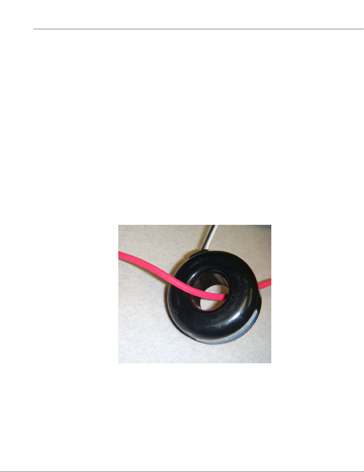
3. Installation
Place one AC load wire through the hole of the CS10-L or CS15-L (see Figure
2).
2
FIGURE 2. AC load wire installed in CS10 (color of ac load wire can
vary)
Page 9
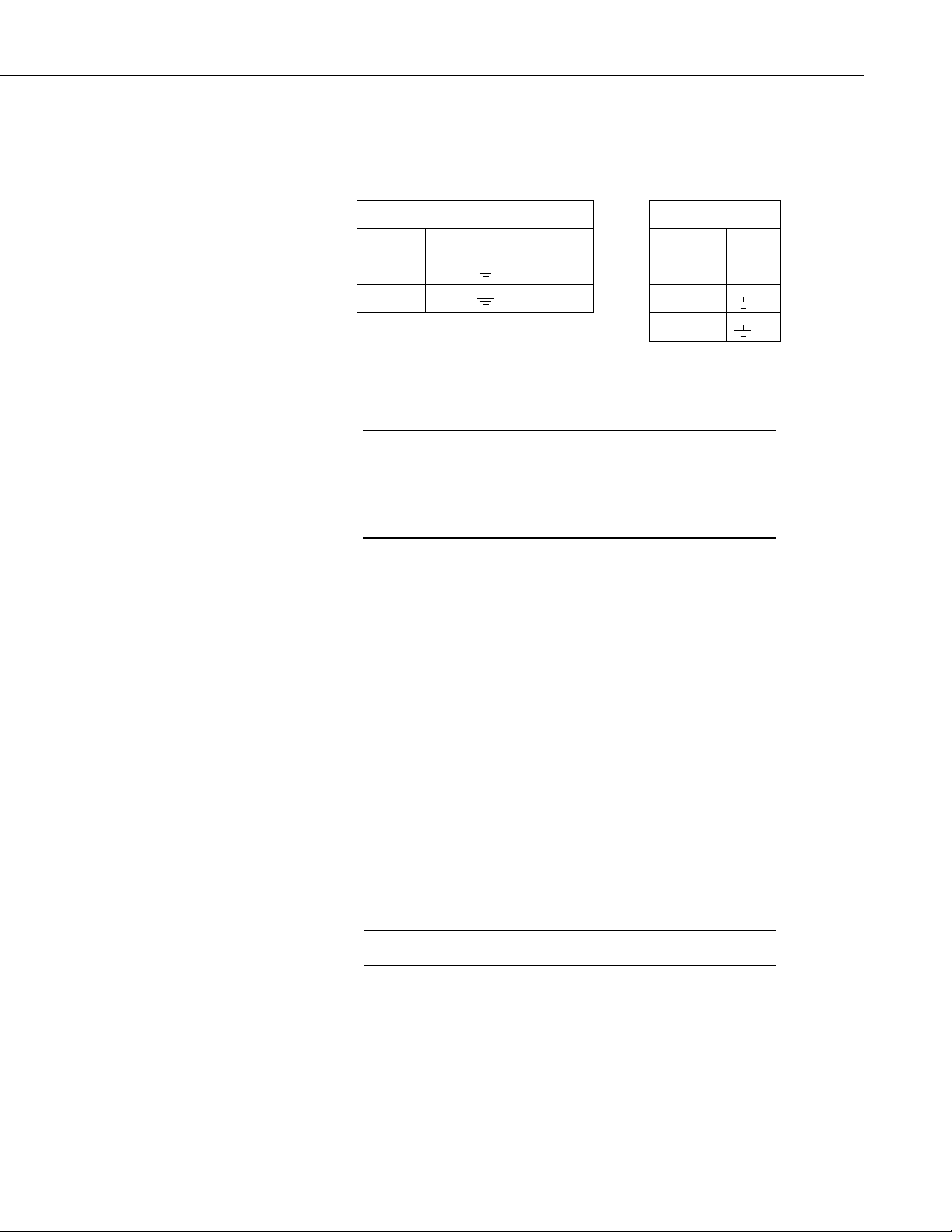
4. Wiring
CS10-L and CS15-L Current Transformers
The CS10-L and CS15-L use a single-ended analog channel as follows.
5. Programming
NOTE
CS10-L
White Single-Ended Channel Red EX
Black AG or White SE
Shield AG or Black
Shield
SCWIN users: This manual was written primarily for those
whose needs are not met by SCWin. Your procedure is much
simpler: just add the CS10-L or CS15 (in the Miscellaneous
Sensors folder), save your program, and follow the wiring shown
in Step 2 of SCWin.
The datalogger is programmed using either CRBasic or Edlog. Dataloggers
that use CRBasic include our CR200(X)-series, CR800, CR850, CR1000, and
CR3000. Dataloggers that use Edlog include our CR510, CR10(X), and
CR23X. In CRBasic, the VoltSE instruction is used to measure the sensor. In
Edlog, a P1 instruction is used.
CS15-L
In order to monitor the amperage of an alternating current circuit, the program
must take many samples from the CS10-L or CS15-L sensor to capture the
waveform over a specified time, and then calculate the average energy under
the curve. There are many methods to do this, depending on the datalogger,
the untapped programming capacity, and other factors.
5.1 CR800, CR850, CR1000, or CR3000 Programming
With these dataloggers, the best method for monitoring amperage is to make
millivolt burst measurements, and then calculate RMS. The millivolt burst
measurements are made by using the VoltSE instruction with multiple reps on
the same channel (i.e., negative value for channel number). The SpaDevSpa
instruction calculates RMS.
NOTE
Program must be run in the pipeline mode.
It is important to get complete cycles. If you make 100 measurements during a
0.1 second time period, you’ll get five complete cycles for a 50 Hz waveform
or six complete cycles for a 60 Hz waveform.
3
Page 10

CS10-L and CS15-L Current Transformers
CAUTION
'CR1000 program to measure rms current
PipeLineMode 'must be pipeline mode
Const num_samples = 100 '100 Samples @ 1000 micro sec = 0.1 second (5 @ 50Hz or 6 @ 60 Hz).
Public Amps 'the line current
Public Amp_mult
Dim i_sig (num_samples) 'to hold the burst measurements, each 100 samples long
PreserveVariables 'to store values between power cycles
DataTable (AmpTable,True,-1)
DataInterval (0,1,Min,10)
Maximum (1,Amps,IEEE4,False,False)
Average (1,Amps,FP2,False)
EndTable
BeginProg
Amp_mult = 0.2 '0.2 multiplier for the CS10-L
Scan (250, mSec, 10, 0)
VoltSe (i_sig (1), num_samples, mV2500,-1, True, 1000, 0, 1.0, 0)
StdDevSpa (Amps, num_samples, i_sig (1))
Amps = Amps * Amp_mult 'put in amps
CallTable (AmpTable)
NextScan
EndProg
Do not average the waveform or use 60 Hz (or 50 Hz)
rejection. Under these circumstances, the amperage value
will always be zero.
Below is an example CR1000 program. In the program, a multiplier of 0.2 is
applied to the RMS value; see Section A.4 for more information.
4
5.2 CR200(X)-series Dataloggers
The CS15 is manufactured specifically for the CR200(X)-series dataloggers. It
has an extra wire and requires an ExciteV instruction in the program. The
voltage excitation creates a positive reference output that the CR200(X)-series
can measure.
The recommended programming method for CR200(X)-series dataloggers
(where the scan interval is limited to once per second) is to place the VoltSE
instruction within a loop. The first CR200(X) example program has a loop that
samples 25 times, and the second CR200(X) example program has a loop that
samples 30 times. A 25-sample loop produces almost two cycles of a 60 Hz
wave form, and a 30-sample loop produces almost two cycles of a 50 Hz wave
form (see Figure 3). The average energy under the curve is calculated using
the RMSSpa instruction. A multiplier of 0.2 is applied to the RMS value; see
Section A.4 for more information.
Page 11

CS10-L and CS15-L Current Transformers
25 Samples of Amperage on CR200(X) Datalogger (60 Hz)
or 30 Samples of Amperage on CR200(X) Datalogger (50 Hz)
80
60
40
20
0
mV
1 3 5 7 9 11 13 15 17 19 21 23 25
-20
-40
-60
-80
Instanteneous Amps
FIGURE 3. Graph of a CS15 waveform
CR200(X) Program for 60 Hz
CS15-L waveform
'CR200(X) Series Datalogger
' Program name: CS15-LManual.cr2
'date: 4 Mar 2009
'program author: Brad Maxfield
Const Samples = 25 ' 25 samples for 2 waves of 60 Hz.
'Const Samples = 30 ' 30 samples for 2 waves of 50 Hz.
Public Crnt_A
Public mV(Samples)
Dim Counter
'Define Data Tables
DataTable (Test,1,-1)
DataInterval (0,1,min)
Average (1,Crnt_A,False)
Maximum (1,Crnt_A,False,0)
EndTable
'Main Program
BeginProg
Scan (1,Sec)
ExciteV (Ex1,mV2500)
For Counter = 1 To Samples
VoltSe (mV(Counter),1,1,1.0,-1250)
Next
ExciteV (Ex1,mV0)
RMSSpa (Crnt_A,(Samples-0),mV(1))
Crnt_A=Crnt_A*0.2 ' Multiplier for sensor
If Crnt_A<0.15 Then ' Eliminate noise below 0.15 amps.
Crnt_A = 0
EndIf
5
Page 12

CS10-L and CS15-L Current Transformers
CallTable Test
NextScan
EndProg
CR200(X) Program for 50 Hz
' CR200(X) Series Datalogger
' Program name: CS15-LManual.cr2
' date: 4 Mar 2009
' program author: Brad Maxfield
Const Samples = 30 ' 30 samples for 2 waves of 50 Hz.
'Const Samples = 25 ' 25 samples for 2 waves of 60 Hz.
Public Crnt_A
Public mV(Samples)
Dim Counter
'Define Data Tables
DataTable (Test,1,-1)
DataInterval (0,1,min)
Average (1,Crnt_A,False)
Maximum (1,Crnt_A,False,0)
EndTable
'Main Program
BeginProg
Scan (1,Sec)
ExciteV (Ex1,mV2500)
For Counter = 1 To Samples
VoltSe (mV(Counter),1,1,1.0,-1250)
Next
ExciteV (Ex1,mV0)
RMSSpa (Crnt_A,(Samples-0),mV(1))
Crnt_A=Crnt_A*0.2 ' Multiplier for sensor
If Crnt_A<0.15 Then ' Eliminate noise below 0.15 amps.
Crnt_A = 0
EndIf
CallTable Test
NextScan
EndProg
6
5.3 CR510, CR10X, CR23X Dataloggers
With these dataloggers, the best method for monitoring amperage is to make
millivolt burst measurements using Instruction 23 and then calculate RMS
using Instruction 82. For Instruction 23, the entry for parameter 4 needs to be
0001. This triggers on the first channel, triggers immediately, stores data in
input locations, and makes single-ended measurements.
Page 13

CS10-L and CS15-L Current Transformers
Remember that it is important to get complete cycles. For Instruction 23, if
parameters 5 and 6 are 2.0 and 0.05, respectively, then you get five complete
cycles for a 50-Hz waveform, and six complete cycles for a 60-Hz waveform
(see Figure 4). The multiplier for the CS10 is 0.2; see Section A.4 for more
information.
Six Cycles at 60 Hz Burst CR10X
I Instanteneous
FIGURE 4. Graph of CS10 waveform using burst mode
The following CR10X program generates the waveforms shown in Figure 4.
NOTE
The instructions listed below do not store data in final storage.
P92, P77, and output processing instructions such as P70 are
required to store the data permanently.
; Parameter 2 should be 2500 mV for 50-200 amps
; should be 250 mV for 5-49 amps
; should be 25 mV for 0-4.9 amps
; Parameter 5 should be 2.0 msec for 50 Hz or 60 Hz
; Parameter 6 should be 0.05 thousand scans for 50 Hz or 60 Hz
; if parameter 5 & 6 are 2.0 and 0.05, then you have 5 complete cycles at 50 Hz
; or 6 complete cycles at 60 Hz.
;
1: Burst Measurement (P23)
1: 1 Input Channels per Scan ; Should always be 1
2: 15 2500 mV Fast Range ; Change according to expected Amperage
3: 1 In Chan ; Change according to Wiring
4: 0001 Trig/Trig/Dest/Meas Options ; Should always be 0001
5: 2.0 Time per Scan (msec) ; Must be 2.0
6: .05 Scans (in thousands) ; Must be 0.05 (for 50 measurements * 2.0 msec = 100 mS)
7: 0 Samples before Trigger ; Should always be 0
8: 0.0 mV Limit ; Should always be 0
9: 0000 mV Excitation ; Should always be 0
10: 4 Loc [ Amps_1 ] ; First location of Block (array)
11: .2 Multiplier ; Match Multiplier of CT:0.2 for CS10-L with 10 ohm shunt
12: 0.0 Offset
2: Z=F x 10^n (P30)
1: 0.0 F
2: 00 n, Exponent of 10
3: 1 Z Loc [ Counter ]
7
Page 14

CS10-L and CS15-L Current Transformers
; This part of the program will calculate the RMS Amperage
; Standard Deviation in this part of the code works mathematically the same
; as RMS calculation, and it is easier to program this way. The RMS
; value is calculated and stored back into an input location for further
; processing if needed.
3: Beginning of Loop (P87)
1: 0 Delay
2: 50 Loop Count
4: Z=Z+1 (P32)
1: 1 Z Loc [ Counter ]
5: If (X<=>F) (P89)
1: 1 X Loc [ Counter ]
2: 1 =
3: 50 F
4: 10 Set Output Flag High (Flag 0)
6: Set Active Storage Area (P80)
1: 3 Input Storage Area
2: 2 Loc [ BurstAmps ]
7: Standard Deviation (P82)^3012
1: 1 Reps
2: 4 -- Sample Loc [ Amps_1 ]
8: End (P95)
5.4 21X, CR7 Dataloggers
Some Edlog dataloggers such as the 21X and CR7 do not have a burst mode.
For those dataloggers, you can use a “Loop Measurement Method” similar to
the method used with the CR200(X). This method is also an option for our
CR510, CR10X, and CR23X, but only three measurements per period will be
made. Figure 5 shows a graph produced by a CR10X program with a loop that
samples 90 times. A portion of this program is shown below.
32 cycles 60 Hz 90 samples in loop on CR10X
FIGURE 5. Graph of a CS10 waveform using 90 samples of amperage
I instant eneous
8
Page 15

CS10-L and CS15-L Current Transformers
NOTE
The instructions listed below do not store data in final storage.
P92, P77, and output processing instructions such as P70 are
required to store the data permanently.
3: Beginning of Loop (P87)
1: 0 Delay
2: 90 Loop Count
4: Z=Z+1 (P32)
1: 4 Z Loc [ Counter ]
5: Volt (SE) (P1)
1: 1 Reps
2: 14 250 mV Fast Range
3: 1 SE Channel
4: 57 -- Loc [ LoopAmp_1 ]
5: .2 Multiplier
6: 0.0 Offset
6: If (X<=>F) (P89)
1: 4 X Loc [ Counter ]
2: 1 =
3: 90 F
4: 10 Set Output Flag High (Flag 0)
7: Z=X (P31)
1: 57 -- X Loc [ LoopAmp_1 ]
2: 3 Z Loc [ Sensor ]
8: Set Active Storage Area (P80)
1: 3 Input Storage Area
2: 2 Loc [ Amp ]
9: Standard Deviation (P82)^12989
1: 1 Reps
2: 3 Sample Loc [ Sensor ]
10: End (P95)
The above CR10X program may provide an adequate waveform because the
program makes more than two measurements per period and samples many
periods. However, if the datalogger’s Burst Measurement Instruction is used
with specific settings, the program will make more measurements per cycle
assuring that complete periods for both 50 and 60 Hz (5 at 50 Hz and 6 at 60
Hz) will be monitored (see Figure 4).
9
Page 16

CS10-L and CS15-L Current Transformers
5.5 CR1000 with Multiplexer Sample Program
This program uses the CR1000 and an AM16/32-series multiplexer to read 32
CS10-L current transformers.
'CR1000 program to measure rms current
PipeLineMode 'must be pipeline mode
Const num_samples = 100 '6 waveforms for 60 Hz, 5 waveforms for 50 Hz
Const NumSensors=32 'Number of Sensors on the Mux MUX in 2X32 Mode *****
'Sensor wired to Low on each of the 32 channels.
'Odd Low on Mux wired to SE2 on Datalogger
Public Amps(NumSensors), i, Batt_Volt 'the line current
Public Amp_mult, TempAmps
Dim i_sig (num_samples) 'to hold the burst measurements, each 100 samples long
PreserveVariables 'to store values between power cycles
DataTable (AmpTable,True,-1)
DataInterval (0,1,Min,10)
Maximum (NumSensors,Amps,IEEE4,False,False)
Average (NumSensors,Amps,FP2,False)
EndTable
BeginProg
Amp_mult = 0.2 '0.2 multiplier for the CS10-L/CS15-L
Scan (10,Sec,0,0)
Battery (Batt_volt)
'Turn AM16/32 Multiplexor On
PortSet(4,1)
i=0
SubScan(0,uSec,NumSensors)
'Switch to next AM16/32 Multiplexer Channel
PulsePort(5,10000)
i=i+1
VoltSe (i_sig (1), num_samples, mV2500,-2, True, 1000, 0, 1.0, 0)
StdDevSpa (Amps(i), num_samples, i_sig (1))
Amps(i) = Amps(i) * Amp_mult 'put in amps
If Amps(i) <= 0.15 Then Amps(i) = 0
NextSubScan
'Turn AM16/32 Multiplexer Off
PortSet(4,0)
CallTable (AmpTable)
NextScan
EndProg
10
Page 17

CS10-L and CS15-L Current Transformers
5.6 CR10X with Multiplexer Sample Program
This program uses the CR10X and an AM16/32-series multiplexer to read 32
CS10-L current transformers.
;{CR10X}
; Example program for CS10-L
;
; Program to test the CS10-L or CS15-L sensor on a CR10X datalogger
; and AM1632 Multiplexer.
;
*Table 1 Program
01: 30 Execution Interval (seconds)
; Turn on the multiplexer
1: Do (P86)
1: 41 Set Port 1 High
2: Excitation with Delay (P22)
1: 1 Ex Channel
2: 0 Delay W/Ex (0.01 sec units)
3: 15 Delay After Ex (0.01 sec units)
4: 0 mV Excitation
3: Beginning of Loop (P87)
1: 0000 Delay
2: 32 Loop Count
; Clock multiplexer to next channel
4: Do (P86)
1: 72 Pulse Port 2
5: Excitation with Delay (P22)
1: 1 Ex Channel
2: 0 Delay W/Ex (0.01 sec units)
3: 1 Delay After Ex (0.01 sec units)
4: 0 mV Excitation
6: Do (P86)
1: 1 Call Subroutine 1
; This part of the program will calculate the RMS Amperage
; Standard Deviation in this part of the code works mathematically the same
; as RMS calculation, and it is easier to program this way. The RMS
; value is calculated and stored back into an input location for further
; processing if needed.
7: Do (P86)
1: 2 Call Subroutine 2
11
Page 18

CS10-L and CS15-L Current Transformers
8: Step Loop Index (P90)
1: 2 Step
9: Z=X (P31)
1: 2 X Loc [ BurstAmps ]
2: 4 -- Z Loc [ CS10_1 ]
10: Do (P86)
1: 3 Call Subroutine 3
11: Z=X (P31)
1: 3 X Loc [ Burst_A2 ]
2: 5 -- Z Loc [ CS10_2 ]
12: End (P95)
13: Do (P86)
1: 51 Set Port 1 Low
; This part of the program will store a one minute average of the amperage.
14: If time is (P92)
1: 0 Minutes (Seconds --) into a
2: 1 Interval (same units as above)
3: 10 Set Output Flag High (Flag 0)
15: Set Active Storage Area (P80)^17815
1: 1 Final Storage Area 1
2: 60 Array ID
16: Real Time (P77)^10331
1: 1220 Year,Day,Hour/Minute (midnight = 2400)
17: Average (P71)^5143
1: 64 Reps
2: 4 Loc [ CS10_1 ]
*Table 2 Program
02: 0.0000 Execution Interval (seconds)
*Table 3 Subroutines
;
; Parameter 2 should be 2500 mV for 50-200 amps
; should be 250 mV for 5-49 amps
; should be 25 mV for 0-4.9 amps
; Parameter 5 should be 2.0 msec for 50 Hz or 60 Hz
; Parameter 6 should be 0.05 thousand scans for 50 Hz or 60 Hz
; if parameter 5 & 6 are 2.0 and 0.05, then you have 5 complete cycles at 50 Hz
; or 6 complete cycles at 60 Hz.
1: Beginning of Subroutine (P85)
1: 1 Subroutine 1
12
Page 19

CS10-L and CS15-L Current Transformers
2: Burst Measurement (P23)
1: 1 Input Channels per Scan
2: 15 2500 mV Fast Range
3: 1 In Chan
4: 0001 Trig/Trig/Dest/Meas Options
5: 2.0 Time per Scan (msec)
6: .05 Scans (in thousands)
7: 0 Samples before Trigger
8: 0.0 mV Limit
9: 0000 mV Excitation
10: 71 Loc [ Amps_1 ]
11: .2 Multiplier
12: 0.0 Offset
3: Burst Measurement (P23)
1: 1 Input Channels per Scan
2: 15 2500 mV Fast Range
3: 2 In Chan
4: 0001 Trig/Trig/Dest/Meas Options
5: 2.0 Time per Scan (msec)
6: .05 Scans (in thousands)
7: 0 Samples before Trigger
8: 0.0 mV Limit
9: 0000 mV Excitation
10: 123 Loc [ AmpsII_1 ]
11: .2 Multiplier
12: 0.0 Offset
4: End (P95)
5: Beginning of Subroutine (P85)
1: 2 Subroutine 2
6: Z=F x 10^n (P30)
1: 0.0 F
2: 00 n, Exponent of 10
3: 1 Z Loc [ Counter ]
7: Beginning of Loop (P87)
1: 0 Delay
2: 50 Loop Count
8: Z=Z+1 (P32)
1: 1 Z Loc [ Counter ]
9: If (X<=>F) (P89)
1: 1 X Loc [ Counter ]
2: 1 =
3: 50 F
4: 10 Set Output Flag High (Flag 0)
10: Set Active Storage Area (P80)
1: 3 Input Storage Area
2: 2 Loc [ BurstAmps ]
13
Page 20

CS10-L and CS15-L Current Transformers
11: Standard Deviation (P82)^13110
1: 1 Reps
2: 71 -- Sample Loc [ Amps_1 ]
12: End (P95)
13: End (P95)
14: Beginning of Subroutine (P85)
1: 3 Subroutine 3
15: Z=F x 10^n (P30)
1: 0.0 F
2: 00 n, Exponent of 10
3: 1 Z Loc [ Counter ]
16: Beginning of Loop (P87)
1: 0 Delay
2: 50 Loop Count
17: Z=Z+1 (P32)
1: 1 Z Loc [ Counter ]
18: If (X<=>F) (P89)
1: 1 X Loc [ Counter ]
2: 1 =
3: 50 F
4: 10 Set Output Flag High (Flag 0)
19: Set Active Storage Area (P80)
1: 3 Input Storage Area
2: 3 Loc [ Burst_A2 ]
20: Standard Deviation (P82)^6732
1: 1 Reps
2: 123 -- Sample Loc [ AmpsII_1 ]
21: End (P95)
22: End (P95)
End Program
14
Page 21

Appendix A. Theory of Operation
A.1 Typical Electrical Circuit
An example of a typical electrical circuit is a generator that provides energy in
the form of a 60-Hz sine wave. The energy is carried from the point of
generation to the point of consumption via two wires. The generator creates an
electrical load that lights up the light bulb (see Figure A-1).
FIGURE A-1. Generator schematic
If we want to know the consumption (amps) of the load, we need a way to
measure what is passing through the wires.
We can add a sensor into the circuit to measure the amperage going through
the circuit (see Figures A-2 through Figure A-4). This sensor is called a CT or
Current Transformer. Our CS10 and CS15 are current transformers.
A-1
Page 22

Appendix A. Theory of Operation
FIGURE A-2. Schematic of generator with current transformer
A-2
FIGURE A-3. Schematic of current transformer with the wire
Page 23

FIGURE A-4. CS10 with the wire
Appendix A. Theory of Operation
A.2 Current Transformer Description
A current transformer is a special kind of transformer that transfers energy
from one side to another through magnetic fluxes (see Figure A-5).
FIGURE A-5. Magnetic flux schematic
The formula for a transformer is as follows (Equation A):
i
* n1 = i2 * n2 Equation A
1
Where i = amps and n = number of turns or windings
And where n
is the primary winding and n2 is the secondary
1
A-3
Page 24

Appendix A. Theory of Operation
With the current transformer, the primary coils or windings are minimized to
avoid removing power out of the circuit, but still have a signal large enough to
measure (see Figure A-6).
FIGURE A-6. Windings schematic
A tiny bit of the current is transferred to the secondary coil.
We can find the current induced on the secondary windings by solving for i
i
= i1 * n1/n2 Equation B
2
:
2
For Example: The CS10 current transducer has an n2 value of 2000 windings.
If 20 amps pass through the primary winding, the following amperage is
produced on the secondary winding:
= 20 * (1/2000) = 0.01 amp on secondary winding
i
2
A.3 Converting a Milliamp Signal to a Millivolt Signal
After the current is transformed from one level to another level, we need to
convert the amperage signal into a voltage signal so that the datalogger can
measure it.
Use Ohm’s Law (Equation C) to convert amperage to voltage:
E = I * R (E=Volts, I = Amps, R = Ohms) Equation C
For Example: Using our previous example:
E = 0.01 amps * R
A-4
The CS10-L contains a 10-ohm burden (shunt) resistor. Therefore E is:
E = 0.01 amps * 10 ohms = 0.1 volts (or 100 mV)
From these calculations, we can determine if we want slightly better resolution
on the measurement. We can lower the Range Code to 250 mV for some
dataloggers.
Page 25

A.4 Multiplier
Appendix A. Theory of Operation
Use Equation D to calculate the multiplier.
m=C*n
Where, C = a correction constant
If we assume a correction constant of 1, then we can solve for the equation
from the above information.
m = 1 * 2000/1 * (1/10) * (1/1000) = 0.2 multiplier
*(1/R)*(1 V/1000 mV) Equation D
2/n1
A.5 CS10/CS15 Comparison
The CS10 consists of a CR Magnectic’s CR8459 Current Transducer with a
10-ohm burden resistor incorporated into its cable (see Figure A-7). The
resistor allows most of our dataloggers to measure it.
CS10-L
FIGURE A-7. CS10 schematic
The CS15, a modified version of the CS10, was developed specifically for the
CR200(X)-series dataloggers. CR200(X)-series dataloggers require special
treatment because they cannot measure negative values; range is only 0 to
2500 mV (see Figure A-9). To create positive reference, the CS15-L uses
Voltage Excitation to shift the measurement range (see Figures A-8 through A-
10).
A-5
Page 26

Appendix A. Theory of Operation
1250 mV
FIGURE A-8. Adding 1250 mV creates positive output
0 mV
A-6
FIGURE A-9. CS15 schematic
Page 27

Appendix A. Theory of Operation
FIGURE A-10. CS15 measurement range
A-7
Page 28

Appendix A. Theory of Operation
A-8
Page 29

Page 30

Campbell Scientific Companies
Campbell Scientific, Inc. (CSI)
815 West 1800 North
Logan, Utah 84321
UNITED STATES
www.campbellsci.com • info@campbellsci.com
Campbell Scientific Africa Pty. Ltd. (CSAf)
PO Box 2450
Somerset West 7129
SOUTH AFRICA
www.csafrica.co.za • cleroux@csafrica.co.za
Campbell Scientific Australia Pty. Ltd. (CSA)
PO Box 444
Thuringowa Central
QLD 4812 AUSTRALIA
www.campbellsci.com.au • info@campbellsci.com.au
Campbell Scientific do Brazil Ltda. (CSB)
Rua Luisa Crapsi Orsi, 15 Butantã
CEP: 005543-000 São Paulo SP BRAZIL
www.campbellsci.com.br • suporte@campbellsci.com.br
Campbell Scientific Canada Corp. (CSC)
11564 - 149th Street NW
Edmonton, Alberta T5M 1W7
CANADA
www.campbellsci.ca • dataloggers@campbellsci.ca
Campbell Scientific Centro Caribe S.A. (CSCC)
300 N Cementerio, Edificio Breller
Santo Domingo, Heredia 40305
COSTA RICA
www.campbellsci.cc • info@campbellsci.cc
Campbell Scientific Ltd. (CSL)
Campbell Park
80 Hathern Road
Shepshed, Loughborough LE12 9GX
UNITED KINGDOM
www.campbellsci.co.uk • sales@campbellsci.co.uk
Campbell Scientific Ltd. (France)
3 Avenue de la Division Leclerc
92160 ANTONY
FRANCE
www.campbellsci.fr • info@campbellsci.fr
Campbell Scientific Spain, S. L.
Avda. Pompeu Fabra 7-9, local 1
08024 Barcelona
SPAIN
www.campbellsci.es • info@campbellsci.es
Please visit www.campbellsci.com to obtain contact information for your local US or International representative.
 Loading...