

Page 1

CR9000X Measurement and
Control System
Revision: 4/12
Copyright © 1995-2012
Campbell Scientific, Inc.
Page 2

Page 3

Warranty
The CR9000X Measurement and Control System is warranted for thirty-six
(36) months subject to this limited warranty:
“PRODUCTS MANUFACTURED BY CAMPBELL SCIENTIFIC, INC. are
warranted by Campbell Scientific, Inc. (“Campbell”) to be free from defects in
materials and workmanship under normal use and service for twelve (12)
months from date of shipment unless otherwise specified in the corresponding
Campbell pricelist or product manual. Products not manufactured, but that are
re-sold by Campbell, are warranted only to the limits extended by the original
manufacturer. Batteries, fine-wire thermocouples, desiccant, and other
consumables have no warranty. Campbell's obligation under this warranty is
limited to repairing or replacing (at Campbell's option) defective products,
which shall be the sole and exclusive remedy under this warranty. The
customer shall assume all costs of removing, reinstalling, and shipping
defective products to Campbell. Campbell will return such products by surface
carrier prepaid within the continental United States of America. To all other
locations, Campbell will return such products best way CIP (Port of Entry)
INCOTERM® 2010, prepaid. This warranty shall not apply to any products
which have been subjected to modification, misuse, neglect, improper service,
accidents of nature, or shipping damage. This warranty is in lieu of all other
warranties, expressed or implied. The warranty for installation services
performed by Campbell such as programming to customer specifications,
electrical connections to products manufactured by Campbell, and product
specific training, is part of Campbell’s product warranty. CAMPBELL
EXPRESSLY DISCLAIMS AND EXCLUDES ANY IMPLIED
WARRANTIES OF MERCHANTABILITY OR FITNESS FOR A
PARTICULAR PURPOSE. Campbell is not liable for any special, indirect,
incidental, and/or consequential damages.”
Page 4

Assistance
Products may not be returned without prior authorization. The following
contact information is for US and international customers residing in countries
served by Campbell Scientific, Inc. directly. Affiliate companies handle
repairs for customers within their territories. Please visit
www.campbellsci.com to determine which Campbell Scientific company serves
your country.
To obtain a Returned Materials Authorization (RMA), contact CAMPBELL
SCIENTIFIC, INC., phone (435) 227-9000. After an applications engineer
determines the nature of the problem, an RMA number will be issued. Please
write this number clearly on the outside of the shipping container. Campbell
Scientific's shipping address is:
CAMPBELL SCIENTIFIC, INC.
RMA#_____
815 West 1800 North
Logan, Utah 84321-1784
For all returns, the customer must fill out a "Statement of Product Cleanliness
and Decontamination" form and comply with the requirements specified in it.
The form is available from our web site at www.campbellsci.com/repair. A
completed form must be either emailed to repair@campbellsci.com or faxed to
(435) 227-9106. Campbell Scientific is unable to process any returns until we
receive this form. If the form is not received within three days of product
receipt or is incomplete, the product will be returned to the customer at the
customer's expense. Campbell Scientific reserves the right to refuse service on
products that were exposed to contaminants that may cause health or safety
concerns for our employees.
Page 5

CR9000X Table of Contents
PDF viewers: These page numbers refer to the printed version of this document. Use the
PDF reader bookmarks tab for links to specific sections.
Quick Start.................................................................. QS-1
QS1. Setting Up....................................................................................... QS-2
QS1.1 Installing RTDAQ.................................................................. QS-2
QS1.2 Opening Enclosure................................................................. QS-2
QS1.3 Connecting the RS232 Port/ Card Installation....................... QS-2
QS1.4 Powering the Logger.............................................................. QS-3
QS1.5 Setting Up Serial Communications....................................... QS-3
QS1.6 Setting Up IP Communications ............................................. QS-9
QS2. Program Generator Basics ............................................................ QS-12
QS2.1 Program Generator Summary Window................................ QS-12
QS2.2 Program Generator Configuration Window......................... QS-13
QS2.3 Program Generator Scan Window ....................................... QS-14
QS2.4 Program Generator Output Table Window.......................... QS-15
QS2.5 Program Generator Special Configuration........................... QS-16
QS2.6 Program Generator: Save and Download ............................. QS-17
QS3. RealTime Monitoring ................................................................... QS-18
QS5. View Data..................................................................................... QS-20
QS6. Comparison of CR9032 and CR9031........................................... QS-21
Overview..................................................................... OV-1
OV1. Physical Description ......................................................................OV-2
OV1.1 Basic System .........................................................................OV-2
OV1.2 Measurement Modules ..........................................................OV-7
OV1.3 Communication Interfaces ..................................................OV-20
OV2. Memory and Programming Concepts ..........................................OV-20
OV2.1 Memory...............................................................................OV-20
OV2.2 Measurements, Processing, Data Storage............................OV-21
OV2.3 Data Tables..........................................................................OV-21
OV3. Commonly Used Peripherals .......................................................OV-22
OV4. Support Software .........................................................................OV-23
OV5. Specifications...............................................................................OV-27
1. Installation.................................................................1-1
1.1 Enclosure .............................................................................................. 1-1
1.1.1 Connecting Sensors..................................................................... 1-1
1.1.2 Quick Connectors ....................................................................... 1-1
1.1.3 Junction Boxes............................................................................ 1-2
1.2 System Power Requirements and Options............................................ 1-3
1.2.1 Power Supply and Charging Circuitry........................................ 1-3
1.2.2 Connecting to Vehicle Power Supply ......................................... 1-5
1.2.3 Solar Panels................................................................................. 1-6
1.2.4 External Battery Connection....................................................... 1-6
1.2.5 Safety Precautions....................................................................... 1-7
i
Page 6

CR9000X Table of Contents
2. Data Storage and Retrieval ..................................... 2-1
1.3 Humidity Effects and Control............................................................... 1-7
1.3.1 Desiccant..................................................................................... 1-7
1.3.2 Nitrogen Purging......................................................................... 1-7
1.4 Recommended Grounding Practices..................................................... 1-8
1.4.1 Protection from Lightning........................................................... 1-8
1.4.2 Operational Input Voltage Limits: Effect on Measurements....... 1-8
1.5 Use of Digital Control Ports for Switching Relays............................... 1-9
2.1 Memory/Data Storage in CR9000X...................................................... 2-1
2.1.1 Internal Flash Memory................................................................ 2-1
2.1.2 Internal Synchronous DRAM...................................................... 2-1
2.1.3 PCMCIA PC Card....................................................................... 2-1
2.2 Internal Data Format ............................................................................. 2-2
2.2.1 NAN and ±INF............................................................................ 2-3
2.3 Data Collection .....................................................................................2-5
2.3.1 The Collect Menu........................................................................ 2-5
2.3.2 Table Monitor Window Save to File........................................... 2-7
2.3.3 File Control Files Retrieval ......................................................... 2-7
2.3.4 Logger Files Retrieval Via PCMCIA PC Card ........................... 2-8
2.3.5 Converting File Format ................................................................ 2-9
2.4 Data Format on Computer................................................................... 2-10
2.4.1 Data File Header Information ...................................................2-10
2.4.2 TOA5 ASCII File Format .........................................................2-13
2.4.3 TOB1 Binary File Format ......................................................... 2-14
2.4.4 TOB3 Binary File Format ......................................................... 2-14
3. CR9000X Measurement Details .............................. 3-1
3.1 Measurements using the CR9041 A/D.................................................. 3-1
3.1.1 Analog Voltage Measurement Sequence ....................................3-1
3.1.2 Single Ended and Differential Voltage Measurements ............... 3-3
3.1.3 Signal Settling Time.................................................................... 3-8
3.1.4 Thermocouple Measurements ................................................... 3-10
3.1.5 Bridge Resistance Measurements.............................................. 3-18
3.1.6 Measurements Requiring AC Excitation................................... 3-20
3.1.7 Influence of Ground Loop on Measurements ...........................3-20
3.2 CR9058E Isolation Module Measurements ........................................ 3-21
3.2.1 CR9058E Supported Instructions.............................................. 3-22
3.2.2 CR9058E Sampling, Noise and Filtering.................................. 3-24
3.2.3 CR9058E; Hard Setting the Filter Order................................... 3-27
3.3 CR9052 Filter Module Measurements................................................ 3-30
3.4 Pulse Count Measurements................................................................. 3-35
3.4.1 CR9070 PulseCount Resolution................................................ 3-35
3.4.2 CR9071E PulseCount Resolution .............................................3-37
3.4.3 CR9071E TimerIO for Measuring Frequency Inputs................ 3-38
3.4.4 High Frequency Pulse Measurements ....................................... 3-38
4. CRBasic – Native Language Programming ........... 4-1
4.1 Introduction to Writing CR9000X Programs........................................ 4-1
4.1.1 ShortCut ......................................................................................4-1
4.1.2 Program Generator ...................................................................... 4-1
ii
Page 7

CR9000X Table of Contents
4.1.3 CRBasic Program Editor............................................................. 4-2
4.1.4 Programming CRBASIC's "Basics":........................................... 4-3
4.2 CRBasic Programming ......................................................................... 4-6
4.2.1 Fundamental elements of CRBASIC include: ............................ 4-6
4.2.2 Numerical Entries ....................................................................... 4-7
4.2.3 Programming Structure............................................................... 4-7
4.2.4 Declarations .............................................................................. 4-11
4.2.5 Constants................................................................................... 4-19
4.2.6 Flags.......................................................................................... 4-19
4.2.7 Parameter Types........................................................................ 4-20
4.2.8 Data Tables ............................................................................... 4-20
4.2.9 Measurement Timing and Processing....................................... 4-24
4.2.10 CRBasic Measurement Instructions........................................ 4-29
4.2.11 Expressions ............................................................................. 4-34
4.3 Program Access to Data Tables.......................................................... 4-39
5. Program Declarations ..............................................5-1
6. Data Table Declarations and Output Processing
Instructions ...........................................................6-1
6.1 Data Table Declaration ......................................................................... 6-1
6.2 Trigger Modifiers ................................................................................. 6-2
6.3 Export Data Instructions..................................................................... 6-11
6.4 Output Processing Instructions........................................................... 6-13
7. Measurement Instructions .......................................7-1
7.1 Voltage Measurements ......................................................................... 7-3
7.2 Thermocouple Measurements............................................................... 7-5
7.3 Resistive Bridge Measurements............................................................ 7-9
7.3.1 Electrical Bridge Circuits............................................................ 7-9
7.3.2 Bridge Excitation ........................................................................ 7-9
7.3.3 Half Bridges.............................................................................. 7-10
7.3.4 Full Bridges............................................................................... 7-13
7.4 Self Measurements.............................................................................. 7-15
7.5 Peripheral Devices.............................................................................. 7-16
7.6 Pulse/Timing/State Measurements....................................................... 7-36
7.7 Serial Sensors ..................................................................................... 7-42
7.8 CR9052DC & CR9052IEPE Filter Module........................................ 7-43
8. Processing and Math Instructions ..........................8-1
9. Datalogger Control ...................................................9-1
9.1 Program Structure/Control.................................................................... 9-1
9.2 Datalogger Status/Control .................................................................. 9-27
9.3 File Control......................................................................................... 9-53
10. Custom Keyboard Display Menus.......................10-1
iii
Page 8

CR9000X Table of Contents
11. String Functions .................................................. 11-1
Appendices
A. Keywords and Predefined Constants.................... A-1
B. Filter Module Available Scan Rates....................... B-1
C. PC/CF Card Information..........................................C-1
11.1 Expressions with Strings................................................................... 11-1
11.1.1 Constant Strings ...................................................................... 11-1
11.1.2 Add Strings ............................................................................. 11-1
11.1.3 Subtraction of Strings.............................................................. 11-1
11.1.4 String Conversion to/from Numeric........................................ 11-1
11.1.5 String Comparison Operators.................................................. 11-2
11.1.6 Sample () Type Conversions and other Output Processing
Instructions ..........................................................................11-2
11.2 String Manipulation Functions.......................................................... 11-2
D. Status Table .............................................................D-1
E. Glossary ................................................................... E-1
E.1 Terms....................................................................................................... 1
E.2 Concepts ................................................................................................ 11
E.2.1 Accuracy, Precision, and Resolution ........................................... 11
Index.........................................................................Index-1
iv
Page 9
Quick Start
QS-1
Page 10
Quick Start
p
y
QS1. Setting Up
QS1.1 Installing RTDAQ
QS1.2 Opening Enclosure
A CD with one licensed copy of RTDAQ is provided with every CR9000X.
Locate and install RTDAQ onto a computer with Windows 2000, XP, or
Vista. It is best to install RTDAQ in a sub folder called RTDAQ under a
CampbellSci directory in your root directory.
The CR9000XC and the
CR9000X with Environmental
Enclosure have air-tight seals. It
may be required to press the gas
relief valve on the side of the
enclosure to equalize the internal
and atmospheric pressures in
order to o
en the enclosure.
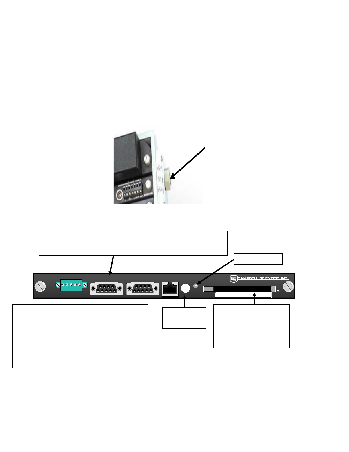
QS1.3 Connecting the RS232 Port/ Card Installation
A nine pin serial cable is supplied with your CR9000X. Plug one end into
your laptop COM port and the other to the CR9032 module's RS232 nine pin
communication port.
+12 G C1 C2 C3
SDM
CR9032 CPU
When using a Card, the process to remove it is to press
the "Card Removal" button and wait for the Card
Status Led to turn green.
CARD STATUS LED:
Not Lit: No card detected.
Red: Accessing the card
Yellow: Corrupt Card, Error
Green: Can safel
remove card
RS-232 CS I/O ETHERNET CARD PC-CARD
STATUS
CONTROL
Card Removal
Button
Card Status LED
Top of Card Faces Down
If you have either a Type II
Flash card or a compact flash
card, format it (CR9000X
accepts FAT16 or FAT32
formats) and install it into the
PC card slot, face down.
MADE IN USA
QS-2
Page 11
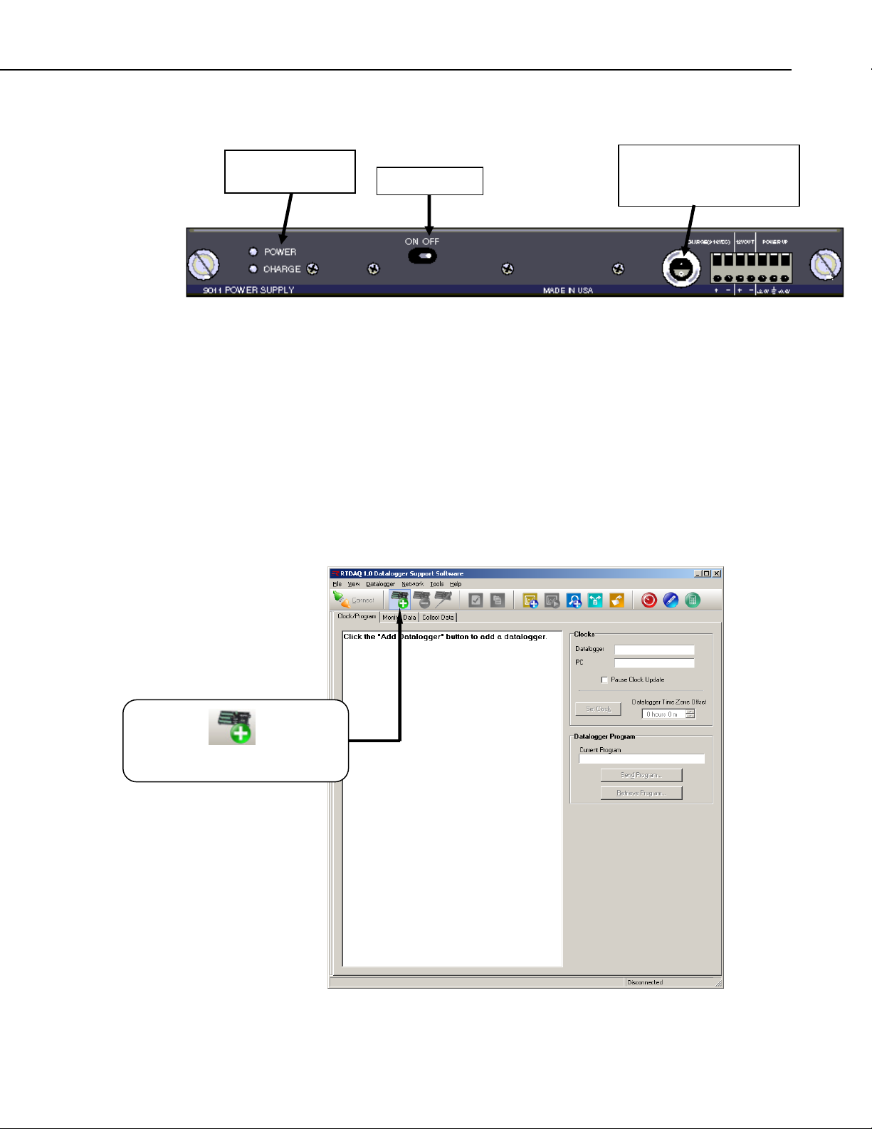
QS1.4 Powering the Logger
g
Quick Start
Power and Charge
LED Li
hts
On/Off Switch
A universal power adapter that can convert 120/240 AC to the required DC
voltage is supplied with the CR9000X(C). The adapter has a Limo
connector which mates with the CR9011 Power Supply module. Connect
the Limo connectors and plug the adapter into the AC wall outlet. The
Charge LED should turn red. You are now ready to power up the CR9000X
with the On/Off toggle switch.
QS1.5 Setting Up Serial Communications
Connect a straight through RS-232 cable from your computers serial port to
the RS-232 port on the CR9032. Start up RTDAQ. You should see the
Window shown below. Click on the Icon with a data logger + sign to start
the Wizard to set up a new CR9000X.
Limo connector for
connection to universal AC
power adapter.
Click on to set up
a CR9000X
datalogger.
QS-3
Page 12
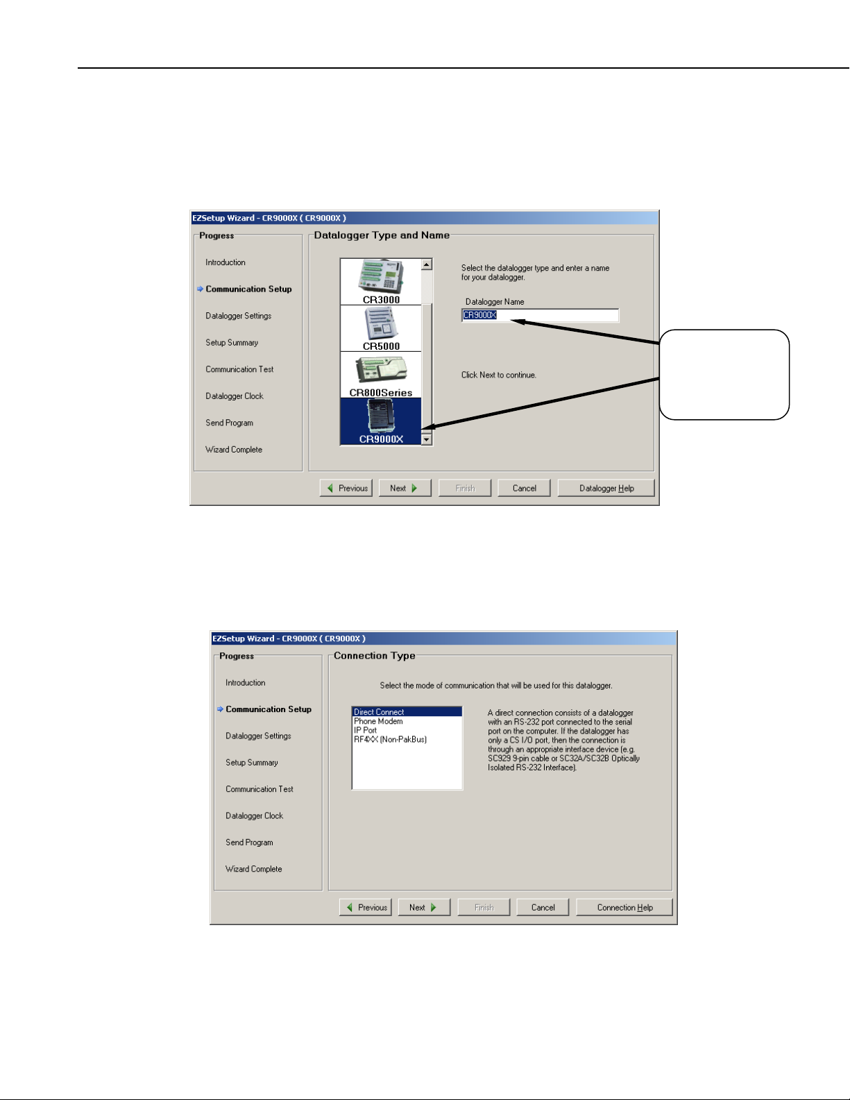
Quick Start
The wizard will prompt you sequentially through the settings required for
your RS232 communication set-up. In this window, scroll down through
the logger types and select the CR9000X. You can enter a descriptive
name for the datalogger set-up. It should be noted that this name is used
solely for the software and does not affect the "Station Name" internal of
the logger.
Select the
CR9000X and
enter a name for
the logger set-up.
Click on Next.
Select "Direct Connect" for your communication mode.
QS-4
Page 13

Quick Start
y
Select the computer COM Port that you will be using to communicate
with the logger. Only COM ports which are recognized and made
available by the PC's operating system will be listed.
Enter 4 seconds for the Com Port Communication Delay. Click "Next".
Select the
COM Port
from the pull
down list, and
enter 4 seconds
for the Port
Comm Dela
.
Select the desired
Baud Rate
Enter 3 for the
Extra Response
Time
Enter 0 for the
Max Time Online.
Enter the Baud Rate supported by your computer, up to 115200 baud.
Enter 3 or 4 seconds for the Extra Response Time and 0 for the Max
Time On-Line. Click on "Next".
QS-5
Page 14
Quick Start
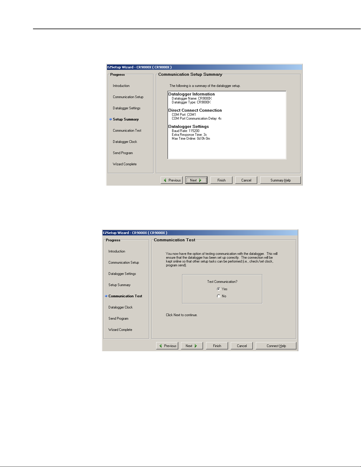
This next window has a Synopsis of your selected options. Verify that it
has the requisite settings and click on "Next".
You will now have the option to Test your Communications link. If you
are connected to a logger, select "Yes", and click on "Next". If you are not
connected to a logger, click on "Finish".
QS-6
Page 15
Quick Start
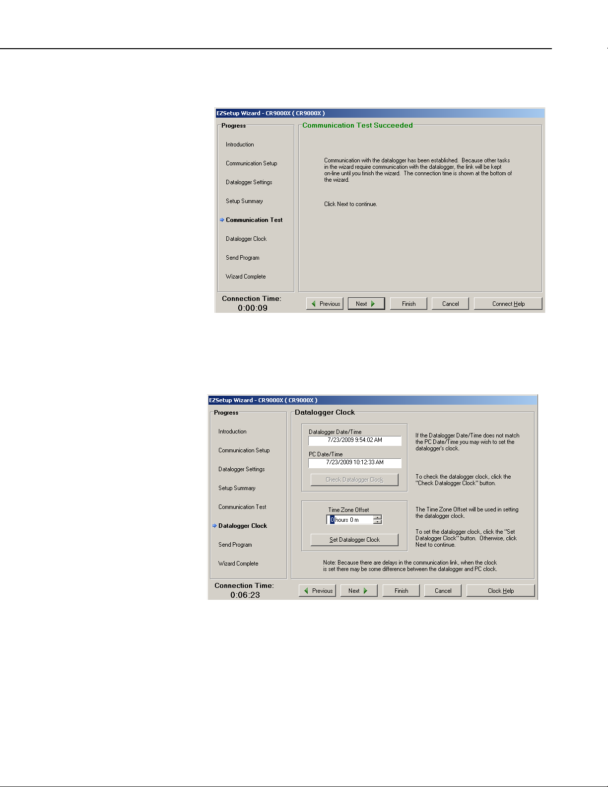
If you have set up the communication link correctly, you should see this
screen. Click on "Next".
The next window is for setting your logger's clock. You have the option to
enter an offset to account for a Time Zone difference between what your
PC is set to and the time zone where the logger will be located. Click on
"Set Datalogger Clock" and then "Next".
QS-7
Page 16
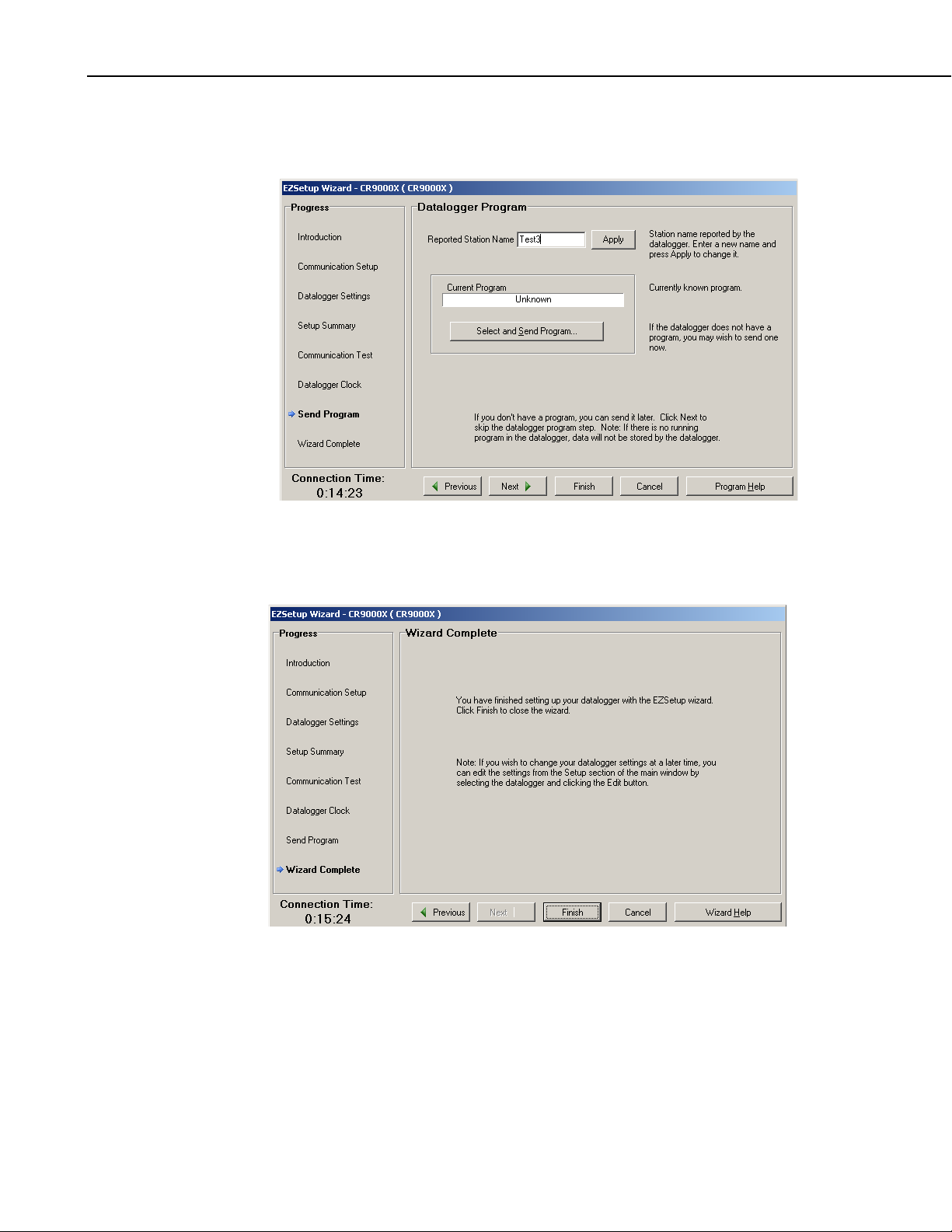
Quick Start
In this next window, the Station Name internal of the logger (Status Table)
is shown and can be modified if desired. A program can also be sent to the
logger if desired. For now, click on "Next".
You are now finished setting up your communication link. Click on
"Finish" and you will be prompted to stay connected to the logger. Click
on "Yes".
QS-8
Page 17
QS1.6 Setting Up IP Communications
b
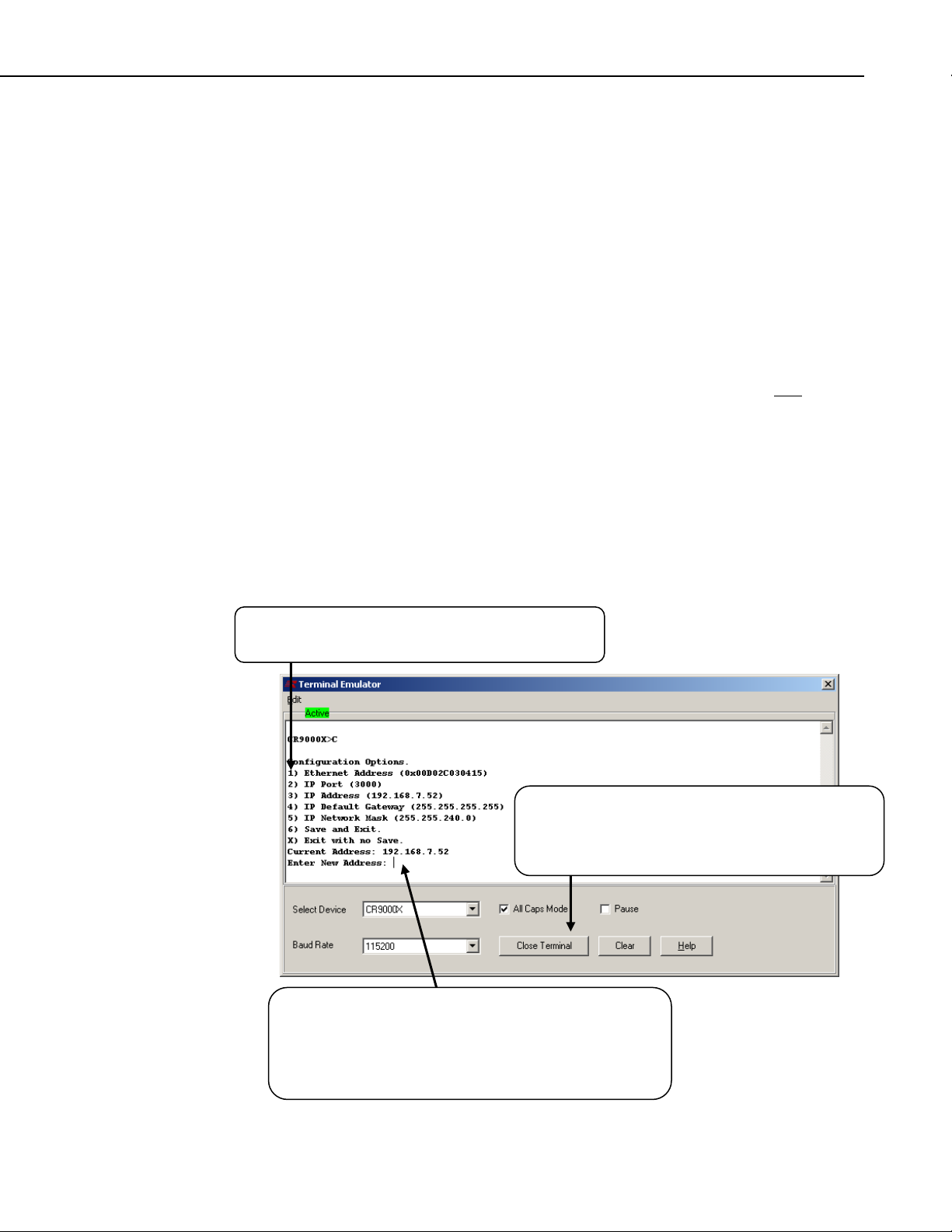
Once serial communications has been established, the CR9000X's IP can be
set. First you have to be connected to the CR9000X through the RS232
port. Next go into RTDAQ's Terminal Mode window
(Datalogger/Terminal Emulator). Click on "Open Terminal" in the "I/O
Port" section and then press <enter> recursively until the "CR9000X"
prompt appears. Press C and <enter>. If you delay for too long, you may
need to press <enter> to re-invoke the CR9000X prompt. The CR9000X's
IP port settings will be shown. To change any of the settings, type in the
associated number, enter the new setting and press <enter>. Once
complete, type in 6 (Save and Exit). Press <enter> until you get the
CR9000X prompt and type in C and <enter> to verify new settings.
For communications across a LAN, or through the Internet, a straight CAT
5 Ethernet cable should be used. For hooking up directly to your PC's
Ethernet port, a CAT 5 Ethernet crossover cable is required.
After the CR9000X's IP settings have been set, you will need to add another
logger communication station, this time setting it up for IP communications
instead of serial communications. Before RTDAQ will allow you to set up
another station, it will be necessary to "Disconnect" from the Serial
Connected Logger (station that we just created). To start, press the Icon
with a data logger + sign to start the Station set-up wizard again. This time
select "IP Port" for the Communication Mode. Once you have setup the IP
station, if communication is still not established, read the section QS1.6.1,
"IP Port Set-up Tips".
Quick Start
To change a setting, type in the associated number and
press <enter>.
First, click on "Open Terminal". Next press <enter>
until the CR9000X prompt is returned. Type in "C"
and <enter> and the CR9000X's I/P port setting will
e returned.
In this example, a 3 (IP Address) was typed in. The
CR9000X responded with the its current IP address and the
software is waiting for a new IP address to be entered.
After changes are made and entered, enter 6 and hit
<enter> to "Save" the new values to the logger.
QS-9
Page 18

Quick Start
QS1.6.1 IP Port Setup Tips
If you are hooking up one or more CR9000Xs on to a Local Area
Network, we recommend that you obtain from your IT department a
value for the SubNet mask and a fixed range of IP addresses for the(se)
CR9000X(s). This will ensure that you are operating within the
requirements set by your IT department, and should eliminate conflicts with
other Ethernet devices on your LAN. No two devices may share an IP
address.
Many Networks are configured to provide dynamic IP addressing (every
time you log onto the Network, your PC is assigned a new IP address). If
your computer is set-up for Dynamic IP addressing, when it is booted up
without being connected to your LAN, its IP address will be set to
000.000.000.000. This setting disables the IP port and network routing for
your computer; i.e. you will not be able to communicate with the
CR9000X. If the computer is booted while connected to the LAN and
receives an IP address, this address should remain in effect until the
computer is rebooted. You can determine whether or not your PC is set-up
for Dynamic Addressing, as well as the current IP address and Subnet Mask
settings for the computer, by going to your Control Panel: Control
Panel/Network Connections/Local Area Network/Properties/ scroll to
Internet Protocol and click on Properties. If "Obtain an IP address
automatically" is clicked on, then your PC is set-up for Dynamic IP
addressing. If the PC was booted up without being connected to the LAN,
remove this selection and enter a IP address and mask.
See Section QS1.6.1.1 Subnet Mask and IP Settings for more on IP
Address and Mask settings.
It should be noted that the CR9000X requires a static IP address. If the
CR9000X will be hooked up to a LAN, this static IP address should be
provided by the IT department. Although the CR9000X may have left
the manufacturer with an IP address and Subnet Mask, these values should
be changed for communications on your LAN.
If you are communicating with the CR9000X using a computer that is never
hooked up to a Network, you can easily choose the Mask and IP addresses
for the CR9000X and the PC. The same mask should be used for both the
CR9000X and the PC. An example of a good Mask setting is
255.255.255.0. Using this Mask setting, the first three bytes of the PC's and
the CR9000X's IP addresses would need to be set to identical values while
the fourth byte could be set to anything from 0 to 255 (example: PC IP
address set to 223.240.0.1 and the CR9000X set to 223.240.0.2). After
changing the computer's IP port settings, you will need to re-boot before the
new settings will be activated. The PC's and CR9000X's IP addresses
cannot be identical.
QS-10
Page 19

QS1.6.1.1 Subnet Mask and IP Settings
The SubNet Mask is a decimal equivalent of a 4-byte binary address. For
any bit set high in the computer's Mask, the corresponding bit in the IP
addresses, for devices that will be communicating with each other, must be
identical.
Example: A PC's SubNet Mask is set to 255.255.240 (binary representation:
is 11111111.11111111.11110000.00000000). For two devices to
communicate, the first two bytes of their IP addresses must be identical.
The first 4 bits of the third byte must also match. So if the third byte for the
PC's IP address is set to 192 (11000000), then any other device that is to
communicate with this PC would need to have the third byte set to
1100XXXX (first 4 bits identical). For this example, a third byte of
11000001 (193) or 11000011 (195) would work. Even 11000000 (192)
would work as long as the fourth byte is not identical for the two devices.
As the PC's Mask fourth byte is all zeros, none of its bits for the two
devices' IP addresses need to match.
It should be remembered that two devices on a network, or that will be
communicating with each other, should not have identical IP addresses. So
for the Subnet Mask of 255.255.240.0, one example of a good pair of IP
addresses is 128.255.192.1 and 128.255.192.2.
Quick Start
If the PC has a fixed IP address, set the CR9000X's Mask to the value of
the PC's SubNet mask, and use the above to determine the CR9000X's IP
address. Example, the PC mask is 255.255.255.0, and its IP address is
192.168.240.3. Valid IP address for the logger would be
192.168.240.XXXX, with XXXX ranging from 0 to 255 with the exception
of 3 (cannot be identical).
If you are using a computer that will be hooked up to a Network, then your
IT people should provide you information on what values you should use
for the SubNet mask and the IP address.
QS-11
Page 20
Quick Start
QS2. Program Generator Basics
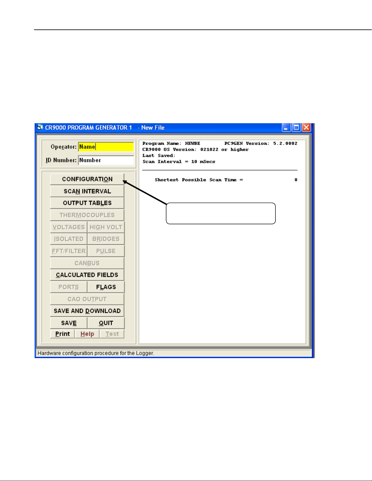
QS2.1 Program Generator Summary Window
Access RTDAQ's Program Generator for the CR9000X using the green
calculator ICON at the right of the main tool bar. If a CR5000 Program
Generator window is invoked, click on File/New/CR9000X.
This Summary window will be shown.
Click on Configuration to enter your
Loggers configuration.
QS-12
Page 21
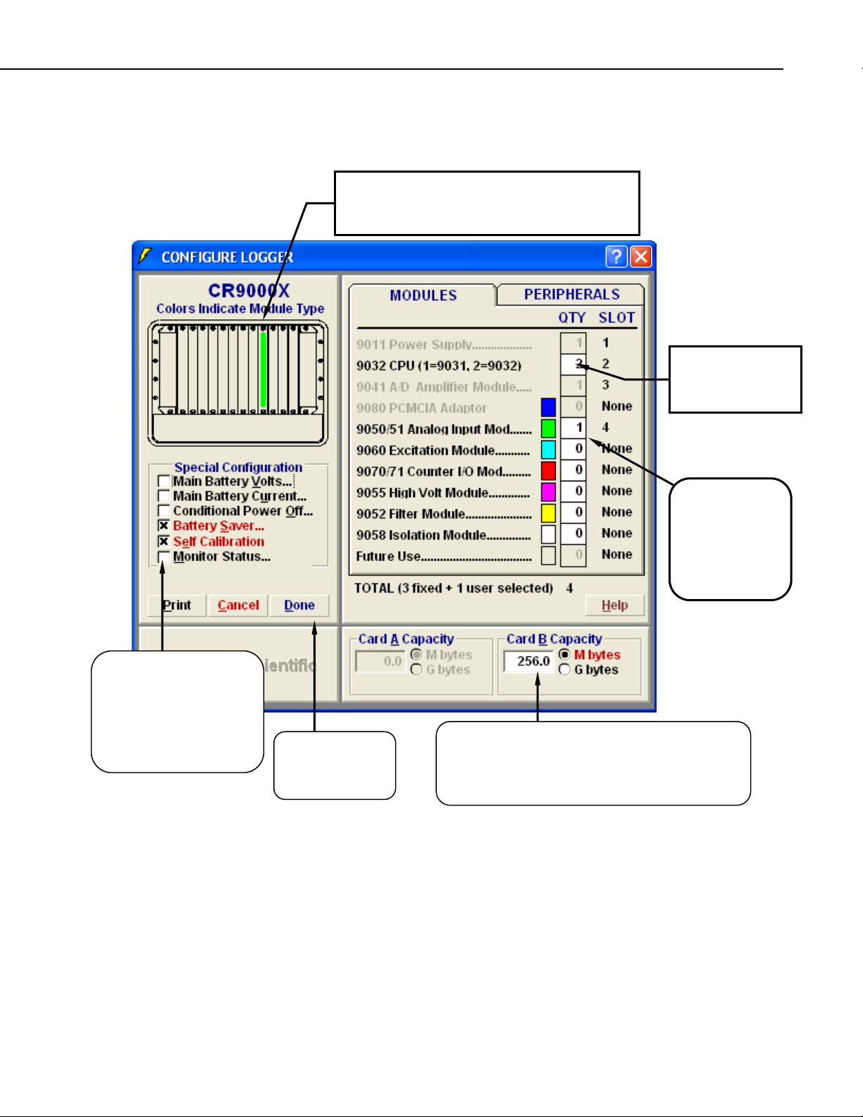
QS2.2 Program Generator Configuration Window
(
Colors match the colors of the module names to
the right. The modules must be inserted into the
Quick Start
Enter a 2 for the
CPU Type
CR9032 CPU).
When checked, these
boxes create the code to
perform special
functions. We will be
selecting some of these
later.
Click on Done
to save your
selections.
Enter the number
and type of
modules that you
will be using in
your CR9000X.
Enter the size of the PCMCIA memory card used in
the CR9032 module's PC card slot. This value will
be used to estimate the amount of remaining
memory in the Output Tables window.
QS-13
Page 22

Quick Start
QS2.3 Program Generator Scan Window
SCAN RATE
The values entered here set the scan rate of the program which determines how often the
measurements are made. You may use the scroll bar to set the time value or type the numeric time
value directly into the Scan Interval box. Enter 10 in the Scan Interval box and select mSeconds for
the units. This will create a program that scans 100 times a second.
Enter 100 for the number of Scans
to Buffer. This sets the number
of scans that processing can la
measurements without having
skipped scans (loss of data). The
number of Scans to Buffer is
limited by the available memory
Click on Done
to save your
selections.
g
QS-14
Page 23
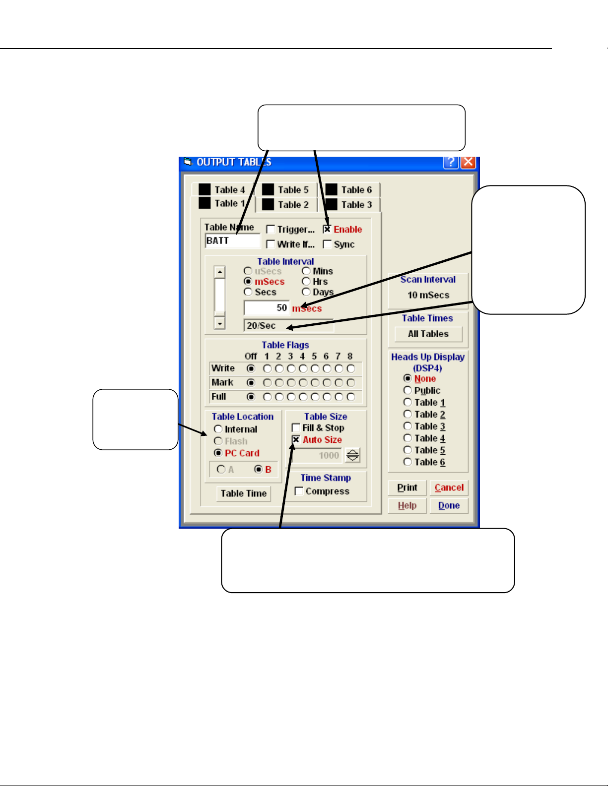
QS2.4 Program Generator Output Table Window
Click on Enable to set-up a Data Table. Click
in the Table Name box and enter a name for
your Data Table (up to 8 characters).
Quick Start
Each table interval is
independently set or
Synchronized to the
program scan interval.
Select mSecs and
enter 50 in the
numeric box (output
to the Table at a rate
of 20 Hz).
Select the
media where
the DataTable
is to be stored
Check the Auto Size box. This will cause the CR9000X to allocate
the largest possible table size for the media selected at compile time.
Specified table sizes will be allocated first, then memory for the
auto-size tables will be allocated to fill at nearly the same time.
Output tables are the data bases created by the CR9000X. They may either
reside within the CR9000X memory or on PCMCIA cards, and may be
accessed with the real-time capabilities of the RTDAQ software. The
Program Generator allows you to create and configure up to 6 tables. Click
on Done after the Data Table is set up.
QS-15
Page 24

Quick Start
QS2.5 Program Generator Special Configuration
Click on Main
Battery Volts and
Main Battery
Current to invoke
the output dialogue
box.
Next we will go back into the Configuration window to enable the
monitoring of the CR9000X's battery.
Click on Done after
setting up the Battery
measurements.
Click on Public
and Average.
QS-16
Page 25
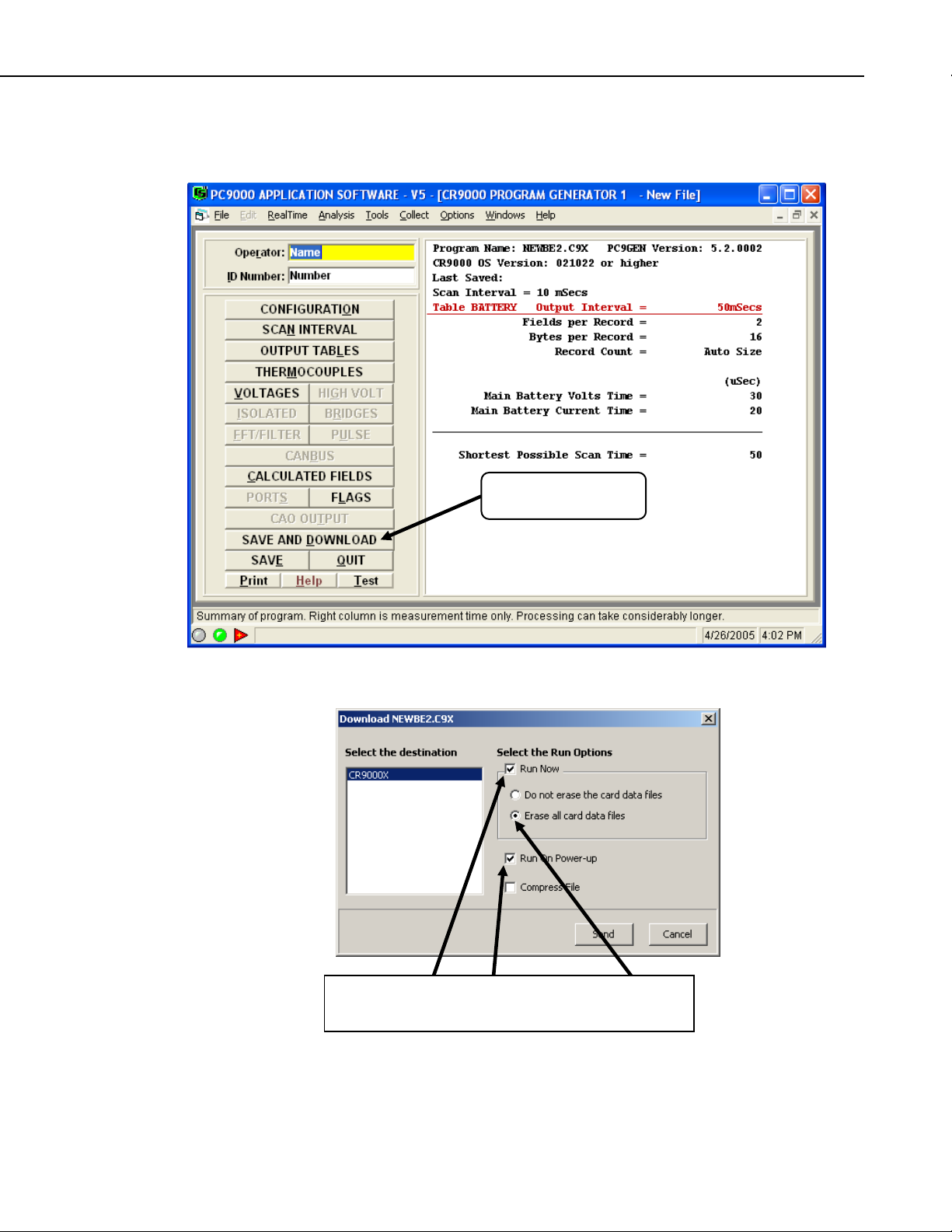
QS2.6 Program Generator: Save and Download
Now we are ready to download the program into the CR9000X.
Click on
Save and Send.
Quick Start
Select a name for the program and "Save" it to a directory on your
computer.
Click on Run Now, Run On Power Up, and Erase all
card data files. Then Click Send.
QS-17
Page 26
Quick Start
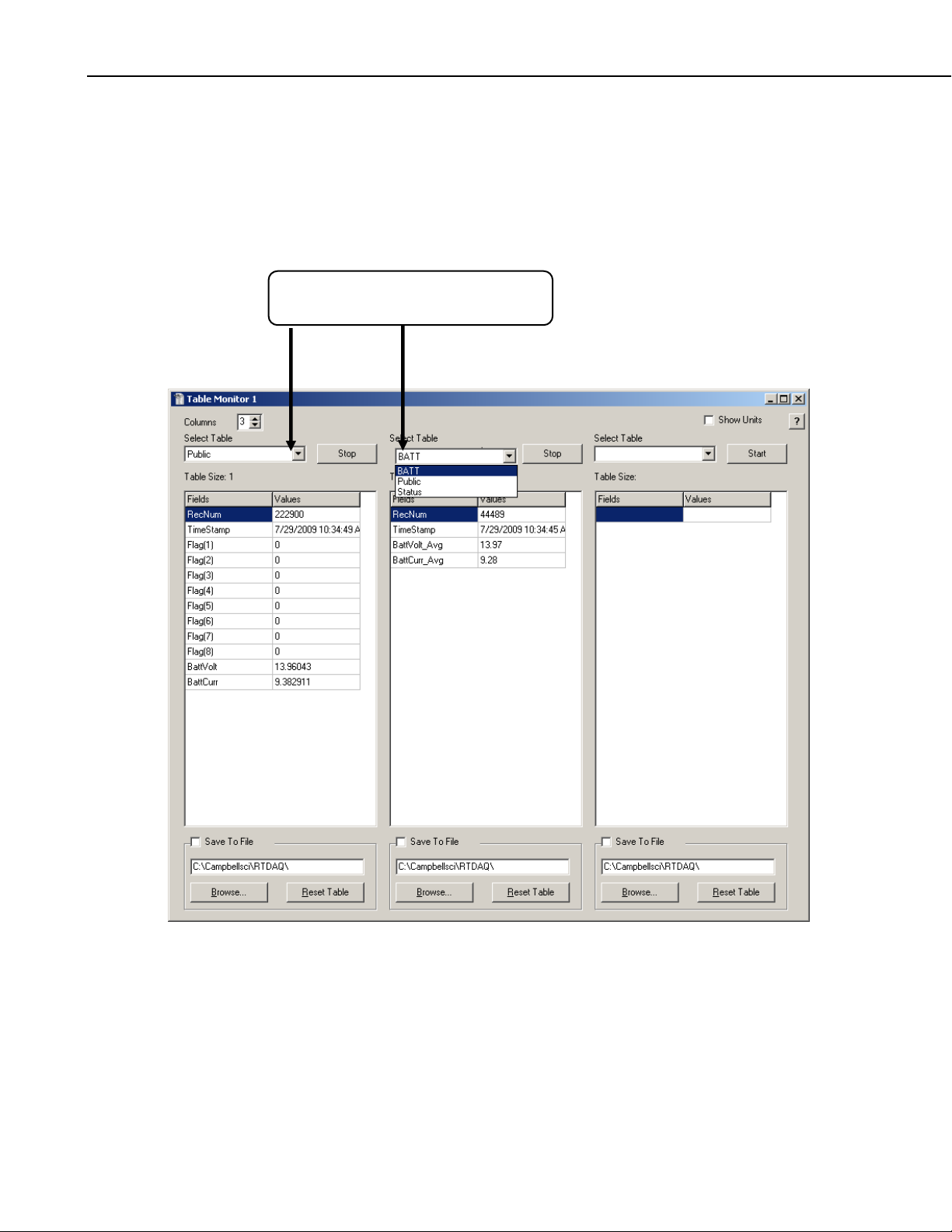
QS3. RealTime Monitoring
The Table Monitor window can be accessed from RTDAQ's "Monitor
Data" tab. From the Icons available, select Table Monitor. Up to three
Tables can be displayed on a single instance of a Table Monitor window.
Simply select the Table(s) to monitor from the pull down list.
Select Public and Batt from the pull
down list of available Data Tables.
QS-18
Page 27
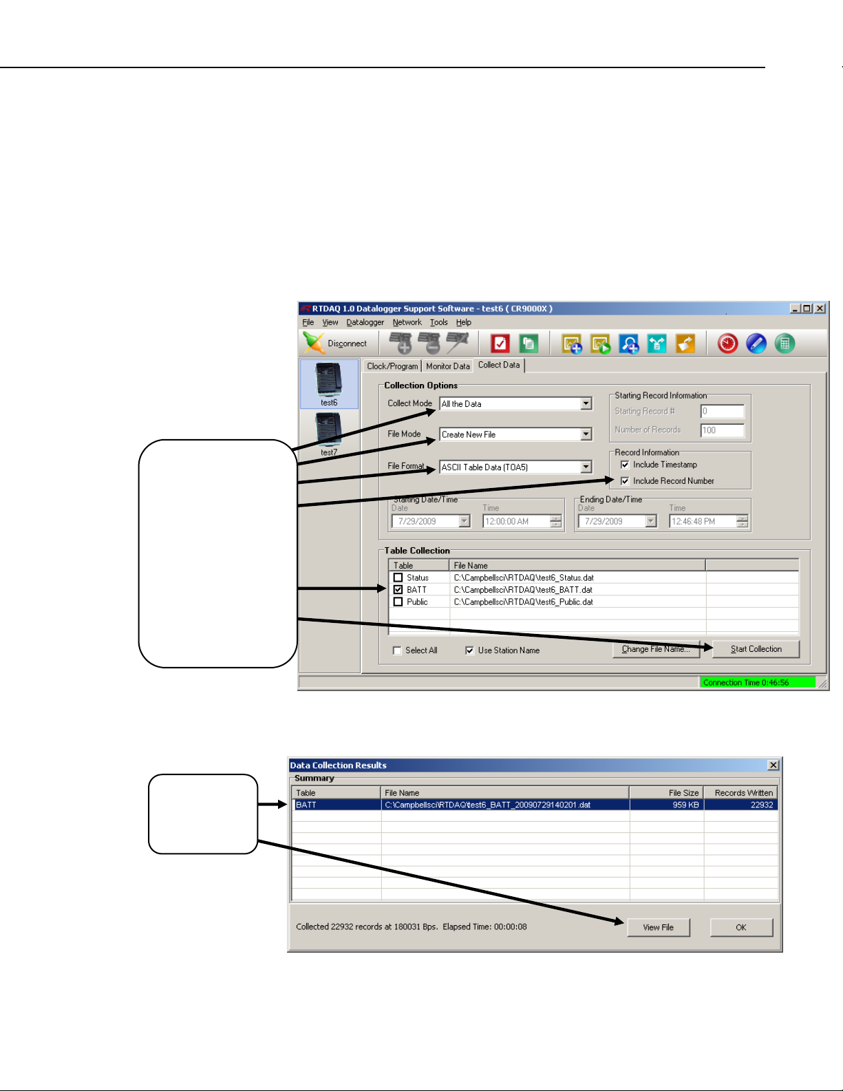
QS4. Data Collection
The Collect window can be accessed from RTDAQ's Collect Data tab.
There are options for setting-up the collection mode, the file mode, and file
format for the data collection process. The file name and path can also be
set here. The default path and name would be:
C:\CampbellSci\RTDAQ\LoggerName_TableName.dat; where
LoggerName = The name user defined name in RTDAQ's network
TableName = The name of the data table in the logger.
Quick Start
map.
Select
All the Data,
Create New File and
AS
CII Data
w/ Time Stamps and
Record Numbers.
Click off Select All,
select the Batt Data
Table from the list
and then click
Start Collectio
Highlight
Batt, and then
click on
ViewFile.
on
n.
Once the collection is complete, a Data Collection Results window will
appear. Highlight the Table Batt and click on View File.
QS-19
Page 28
Quick Start
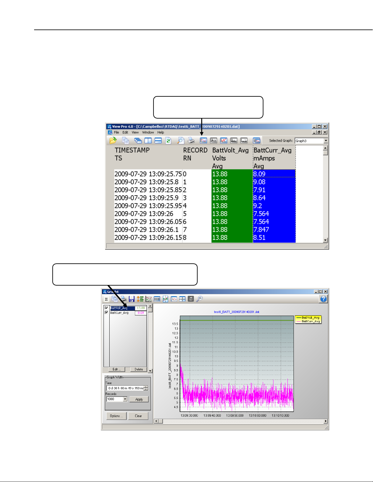
QS5. View Data
The ViewPro utlitity can also be accessed from RTDAQ's main toolbar:
Tools\ViewPro. ViewPro includes a full set of graphing capabilities.
Select one or two columns and click on the Line Graph Icon.
Highlight BattVolt & BattCurr columns
and click on the Line Graph icon.
Right click on trace name and select "Edit Selection"
to change trace properties and set up the X axis.
QS-20
Page 29
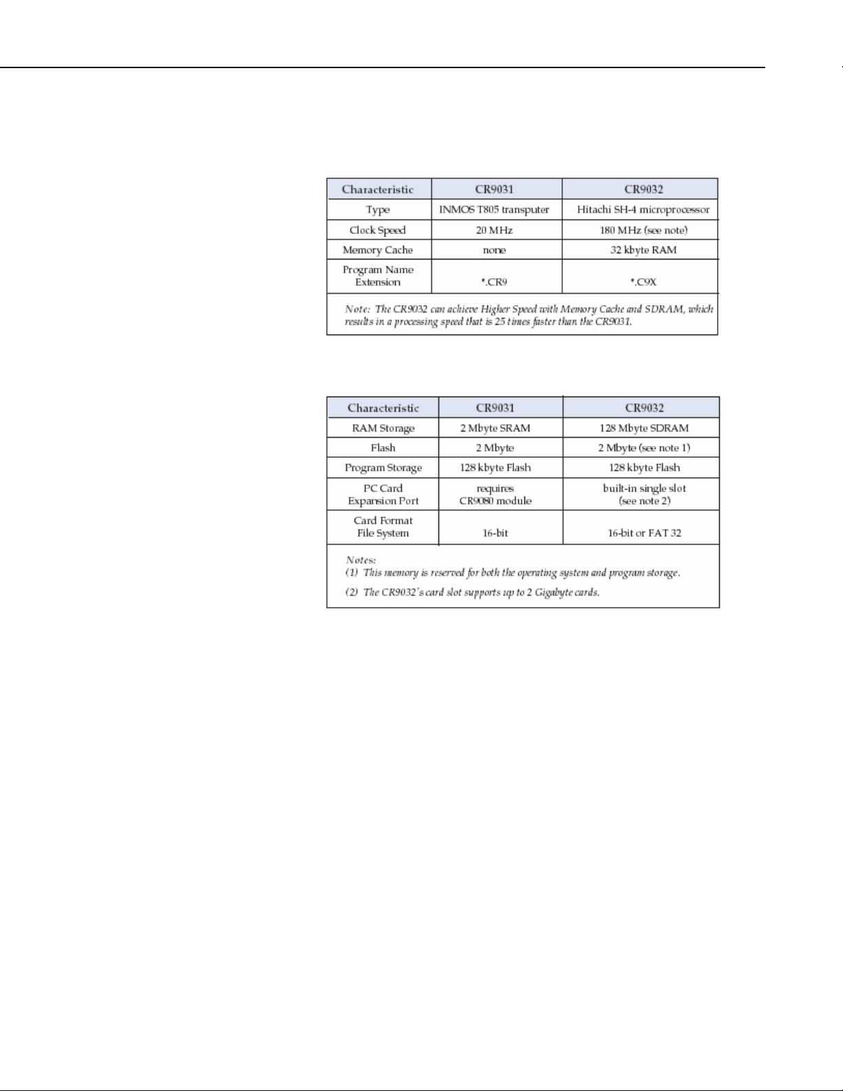
QS6. Comparison of CR9032 and CR9031
Processor
Memory
Quick Start
QS-21
Page 30
Quick Start
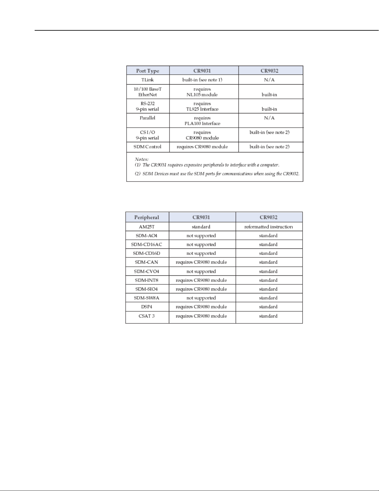
Communication Ports
Peripheral Compatibility
QS-22
Page 31

PC-Card LED Indicator Status
Instruction Set
The CR9031 and CR9032 have similar instruction sets, and many existing
CR9000 programs will function properly without modifications. The
CR9032 includes additional instructions that support capabilities not
provided in the CR9031. Also, some of the CR9031’s instructions have
been modified or removed, and programs containing those instructions will
need to be revised.
Quick Start
New Instructions
QS-23
Page 32

Quick Start
Modified or Removed Instructions
Existing CR9000 programs that include one or more of the following
instructions will need to be revised if the CR9000 is upgraded to a
CR9000X (i.e., the CR9031 module is replaced with the CR9032).
QS-24
Page 33

Overview
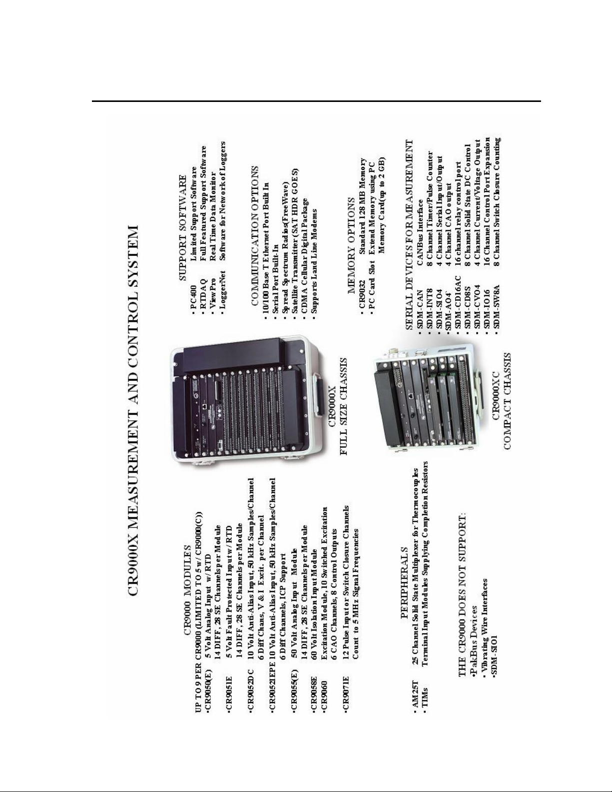
The CR9000X is a modular, multi-processor system that provides precision measurement
capabilities in a rugged,stand-alone, battery-operated package. The system makes
measurements at a rate of up to 100 K samples/second with 16-bit resolution. The
CR9000X Base System includes CPU, power supply, and A/D modules. Up to nine I/O
modules are inserted in the CR9000X, or up to five I/O modules are inserted into the
CR9000XC, to configure a system for specific applications. The on-board, BASIC-like
programming language includes data processing and analysis routines. RTDAQ
Windows
realtime monitoring. LoggerNet software can be used for multiple station applications
requiring modem communications and/or where schedule data collection to a PC is
required.
™
Software provides program generation and editing, data retrieval, and
CR9000
AC ADAPTOR
FIGURE OV1-1. CR9000X Measurement and Control System
OV-1
Page 34

Overview
OV1. Physical Description
OV1.1 Basic System
The basic CR9000X system includes a CR9011 Power supply module, a
CR9032 CPU module, and a CR9041 A/D module. These are installed into a
mother board in an enclosure. Also included in all CR9000X base systems is a
battery, and a wall charger.
There are two sizes of base systems to choose from. The CR9000XC compact
version comes in an aluminum enclosure and can accommodate up to 5
measurement modules. The CR9000X full size chassis can be configured with
a lab enclosure or a fiberglass environmental enclosure and can accommodate
up to 9 measurement modules.
The CR9000XC includes a 7 AHr lithium battery. The CR9000X full size
logger includes two 7 AHr batteries. It is recommended to keep these
batteries from reaching a state of deep discharge (10.5 V) which can damage
the cells.
CR9011 Power Supply Module and AC Adapter
POWER
CHARGE
9011 POWER SUPPLY
ON OFF
MADE IN USA
FIGURE OV1-4. CR9011
The CR9011 Power Supply Module provides regulated power to the CR9000X
from either the internal battery modules or from the 9 to 18 VDC (fuse and
diode protected) charge inputs. It also regulates battery charging (up to 2
amps) from power supplied by the AC adapter, a DC input, or other external
sources. The AC adapter may be used where AC power is available (100 - 240
volts) to provide power to the CR9000X and charge its batteries.
High Current Demand Applications
A DC source with voltage in the range of 9 to 18 VDC will charge the internal
lead acid batteries and power the CR9000X provided sufficient current is
available and the system is set-up to use 3 amps or less. If the CR9000X
system configuration requires greater than 3 amps, consult a CSI applications
engineer for information about the CR9011 Power Supply High-Current
modification.
CHARGE(9-18VDC)
12VOUT POWER UP
>2.0V
<0.8V
OV-2
LEDs There are 2 LEDs: Power and Charge. The Power LED is red if
the logger is powered up. The Charge LED is red to indicate the
presence of a charging source for the batteries.
On/Off The ON/Off toggle switch is used to manually power up and down
the logger. It should be noted that if the toggle switch is in the ON
position, but the Power LED is dark, it could either mean that there
Page 35

Overview
is no power available, the logger has been shut down through
software control or that the internal fuse is blown.
Charge There are two connections, in parallel, for hooking up a 9 to 18
VDC charging source. These connections are fuse and diode
protected. The CR9011's 12VOUT supply is current limited to 300
mA. If a peripheral requires more current, the CR9032 SDM 12
volt out can source up to 1.85 amps.
>2.0V The CR9011 has a relay that allows shutting off power under
program control. The Power Up inputs allow an external signal to
awaken the CR9000X from a powered down state (see the
PowerOff topic in Section 9 9.2 Data Logger Status/ Control).
When the CR9000X is in this "Power Off" state, the On/Off switch
is in the ON position but the internal relay is open and the power
LED is not lit. If the ">2" input has a voltage greater than 2 volts
applied to it (most common usage is 12 Volts), the CR9000X will
awake, load the program in memory and run.
<0.8V If the <0.8 input is shorted to ground during the CR9000X's 2 to 5
second initialization during power-up, any program set to Run On
Powerup will be disabled. This is useful if a program is in some
endless loop and communications cannot be established. Can also
be used to wake up a logger that has been shut down through
software control.
In addition to regulating and supplying power to the logger, the CR9011 keeps
track of the date and time. If the CR9000X system's CR9011 module is
swapped out, the Date/Time will need to be reset. The clock is powered off the
main 12 volt batteries. In addition, there are two backup power sources for the
clock, a lithium battery and a super capacitor, both located on the CR9011
board.
The run time attributes (Run Now, Run on Powerup ..) of the program files are
also stored on the CR9011. If the CR9011 in the system is swapped out for
a different CR9011, the run time attribute settings will no longer be valid
and will need to be reset by the user.
MEASUREMENTS:
Battery (voltage and current)
CONTROL:
PowerOff
Program Run Attributes
ClockSet
See Section 1.2 System Power Requirements and Options for additional
details.
OV-3
Page 36

Overview
CR9032 CPU Module
SDM
CR9032 CPU
+12 G C1 C2 C3
RS-232 CS I/O ETHERNET CARD PC-CARD
STATUS
CONTROL
Top of Card Faces Down
FIGURE OV1-2. CR9032
The CR9032 CPU Module provides system control, processing, and
communication. The CR9032 CPU module is the main processor for the
datalogger as well as memory for program storage and buffering data. The
main processor is a 180 MHz Hitachi SH-4 microprocessor. The module has
128 MB SDRAM and 2 MB Flash EEPROM. 128 KB of the Flash memory is
reserved for program storage.
MADE IN USA
NOTE
The 128 MB of SDRAM is not battery backed and that data that
is stored there will be lost when the logger is powered down or
experiences a watchdog reset.
CRITICAL DATA SHOULD BE STORED ON THE
PCMCIA CARD.
The CR9032 CPU Module provides the following:
SDM Ports C1 through C3 are used for communication with SDM (Synchronous Device
for Measurements) peripherals such as the SDM-CAN or SDM-SIO4. The
SDM 12 volt supply is current limited to 1.85 amps and can be used to power
other peripherals besides SDM devices.
RS232 The Datalogger RS-232 port can function as either a DCE (Data
Communication Equipment such as a modem) or DTE (Data Terminal
Equipment such as a computer) device. For the Datalogger RS-232 port to
function as a DTE device, a null modem cable is required. The most common
use of the Datalogger's RS-232 port is a connection to a computer DTE device.
A standard DB9-to-DB9 cable can connect the computer DTE device to the
Datalogger DCE device. Pins 1, 4, 6 and 9 function differently than a standard
DCE device. This is to accommodate a connection to a modem or other DCE
device via a null modem. Pin configuration for the CR9000X RS-232 9-pin
port is listed in TABLE OV1-1.
TABLE OV1-1. Datalogger RS-232 Pin-Out
OV-4
PIN
1 DCD DTR (tied to pin 6) O* Data Terminal Ready
2 TXD TXD O Asynchronous data Transmit
3 RXD RXD I Asynchronous data Receive
4 DTR N/A X* Not Connected
5 GND GND GND Ground
6 DSR DTR O* Data Terminal Ready
7 CTS CTS I Clear to send
8 RTS RTS O Request to send
9 RI RI I* Ring
DCE
Function
Logger
Function
I/O
Description
Page 37

Overview
* Different pin function compared to a standard DCE device. These pins will
accommodate a connection to modem or other DCE devices via a null modem
cable.
I/O Descriptors: O = Signal Out of the CR1000 to a RS-232 device;
I = Signal Into the CR1000 from a RS-232 device,
X = Signal has no connection (floating)
CS I/O CSI 9 Pin port for communications with CSI's peripherals (such as the DSP4).
Table OV1-2 lists the pin configuration for the CR9000X CS I/O port.
TABLE C-1. CS I/O Pin Description
O = Signal Out of the CR9000X to a peripheral.
I = Signal Into the CR9000X from a peripheral.
PIN ABR I/O Description
1 5 V O 5V: Sources 5 VDC, used to power peripherals.
2 SG Signal Ground: Provides a power return for pin 1 (5V),
and is used as a reference for voltage levels.
3 RING I Ring: Raised by a peripheral to put the CR9000X in the
telecommunications mode.
4 RXD I Receive Data: Serial data transmitted by a peripheral are
received on pin 4.
5 ME O Modem Enable: Raised when the CR9000X determines
that a modem raised the ring line.
6 SDE O Synchronous Device Enable: Used to address
Synchronous Devices (SDs), and can be used as an enable
line for printers.
7 CLK/HS I/O Clock/Handshake: Used with the SDE and TXD lines to
address and transfer data to SDs. When not used as a
clock, pin 7 can be used as a handshake line (during printer
output, high enables, low disables).
8 +12 VDC
9 TXD O Transmit Data: Serial data are transmitted from the
CR9000X to peripherals on pin 9; logic low marking (0V)
logic high spacing (5V) standard asynchronous ASCII, 8
data bits, no parity, 1 start bit, 1 stop bit, 300, 1200, 2400,
4800, 9600, 19,200, 38,400, 115,200 baud (user
selectable).
Ethernet Supports 10BaseT or 100baseT communications. An Ethernet crossover
cable is required for hooking up directly to a computer.
There are two LEDs on the Ethernet port. The LED on the lower left of the
port indicates communication speed. If hooked into a 10BaseT link it will be
dark, if hooked into a 100BaseT link it will be lit green.The LED on the lower
right of the port indicates communication traffic. If communications is active,
it should be flashing yellow.
PC Card The CR9000X has a built in PCMCIA card slot that can support cards up to 2
GB in size with a status LED and control button. Removing a card while it is
active can corrupt the data and potentially damage the card. Press Card
removal button and wait for LED to turn green before removing Card. Do not
switch off the power (CR9011 Module) while the cards are present and active
OV-5
Page 38

Overview
(Press card button prior to flipping the power switch). If the logger is powered
off using software control (PowerOff instruction), the data buffered in the CPU
is flushed to the card and the Logger is shut down properly.
NOTE
DO NOT POWER DOWN LOGGER WHILE PCMCIA CARD
IS ACTIVE.
LED code description:
Dark: No card detected or formatted card present without errors
Yellow: Either no card or corrupt card with program trying to access the card
Red: Accessing the card
Green: Can safely remove the card
Only Industrial grade PC cards should be used. They can operate over a wider
temperature range, have better vibration and shock resistance, have faster
read/write times, and can withstand more write cycles than the commercial
grade cards. It should be remembered that a system is only as good as its
weakest link. Do not buy a cheap memory card to store data for a test whose
results are important.
See Appendix C PC/CF Card Information for details on selecting memory card.
Up to a total of 30 data tables, each capable of storing data at different rates,
can be created between the CPU's SDRAM and the PC Card. Data Tables
created on the PC cards will also have a buffer table created in SDRAM. The
size of this buffer can either be manually or auto allocated.
MEASUREMENTS/INSTRUCTIONS THAT DIRECTLY UTLIZE THE
CPU HARDWARE OR COMMUNICATIONS OPTION:
CardOut Output Data to PC Card
CS7500 Open Path CO2/H20 Sensor
CSAT3 CSI Sonic Anemometer
DSP4 DSP4 Heads up Display
SDMA04 Analog Voltage Output Peripheral
SDMCANBus CANBus Interface Peripheral
SDMCD16AC I/O Port Peripheral used for controlling relays
SDMCVO4 Analog Current and Voltage Output Peripheral
SDMINT8 Interval Timer Peripheral
SDMIO16 Control Port Expansion device
SDMSIO4 Serial Input/Output Peripheral
SDMSW8A Switch Closure Measurement Peripheral
CR9041 A D
OV-6
CR9041 A/D and Amplifier Module
CR9000X
MEASUREMENT & CONTROL SYSTEM
LOGAN, UTAH
FIGURE OV1-3. CR9041
The CR9041 A/D and Amplifier Module provides signal conditioning and 16
bit, 100 kHz A/D conversions.
MADE IN USA
Page 39

OV1.2 Measurement Modules
CR9050(E) Analog Input Module
1
3
5
7
9
SE
2
4
6
1
2
H
DIF
H
L
3
H
L
8
4
H
L
L
11
10
5
H
12
6
H
L
L
Overview
13
15
17
19
21
23
25
14
16
18
20
22
7
8
9
10
H
H
H
L
L
H
L
11
H
L
24
12
H
L
L
27
26
13
H
28
14
H
L
L
9050 ANALOG INPUT W RTD
MADE IN USA
FIGURE OV1-5. CR9050
The only difference between a CR9050 and a CR9050E is that the CR9050E is
an "Easy Connect" module type, and includes a CR9050EC. Both the
CR9050E and the CR9051E use the same CR9050EC Easy Connect module
(See Figure OV1-6). The CR9050E typically remains in the CR9000(X)
chassis while each CR9050EC remains connected to the sensors. This allows
one CR9000(X) system to be moved from location to location and be quickly
connected to the sensors on-site.
The CR9050(E) Analog Input Module has 14 differential inputs for measuring
voltages up to ±5 V. Each differential input can be, independently, configured
as two Single Ended inputs. Next to each differential channel, is an analog
ground input. All analog grounds on all CR9050(E), CR9051E, CR9055(E),
CR9060, CR9070, and CR9071E modules in a CR9000X chassis are common.
Diff. Channel H
Differential Channel 1 through 14
Diff. Channel L
.
Sensor
Sensor wired up as a Differential (DIF) input
Each differential analog input can, independently, be setup as 2 single-ended
inputs.
S.E. Channel
Single Ended Channel 1 through 28
Sensor
Ground
Sensor wired up as a Single Ended (SE) input
All inputs on the CR9050(E), CR9051E, and CR9055(E) modules are
multiplexed through the single 16 bit A/D on the CR9041 A/D module. The
maximum aggregate throughput for all channels on all modules is 100,000
samples per second. Resolution on the most sensitive range is 1.6 μV.
OV-7
Page 40

Overview
Full Scale Maximum
Range Resolution Throughput
± 5000 mV 158 uV 100 KHz
± 1000 mV 32 uV 100 KHz
± 200 mV 6.3 uV 100 KHz
± 50 mV 1.6 uV 50 KHz
The CR9050(E) operational input voltage limits are ± 5 volts with reference to
datalogger ground. Voltages exceeding ±9 V with reference to datalogger
ground may cause errors on other channels. When the logger is powered off,
the CR9050(E)'s input impedance drops drastically.
The CR9050(E) contains an on-board PRT, located at the top center of the
module, which provides the reference temperature for thermocouple
measurements. A heavy copper grounding bar and connectors combined with
the aluminum case help to reduce temperature gradients for accurate
thermocouple measurements. If the logger is in an environment that is
experiencing rapid temperature fluctuations, it is recommended that the
CR9000X be insulated to reduce the temperature gradient along the copper bar.
This is true for all modules used to measure thermocouples.
CR9050 SUPPORTED MEASUREMENT INSTRUCTIONS:
Voltage
VoltDiff Differential Voltage
VoltSe Single-Ended Voltage
TCDiff Differential Thermocouple
TCSE Single Ended Thermocouple
NOTE
Bridge measurements (also requires CR9060 Excitation Module)
BrFull Full Bridge
BrFull6W 6 Wire Full Bridge
BrHalf Half Bridge
BrHalf3W 3 Wire Half Bridge
BrHalf4W 4 Wire Half Bridge
Self measurements (reference PRT for thermocouple measurements)
ModuleTemp Module Temperature
See Section 3.1 Measurements using the CR9041 A/D for measurement details.
See Section 7 Measurement Instructions for Instruction details.
The CR9051E is recommended over the CR9050E for
applications where fault voltages beyond ±9 V could come in
contact with the inputs, or when the CR9000X could be powered
off while still connected to sensors that have power applied to
them.
OV-8
Page 41

CR9051E Fault Protected 5 V Analog Input Module
Overview
FIGURE OV1-6. CR9051E with CR9050EC
The number of channels are the same as for the CR9050(E) Analog Input
Module. This module includes an Easy Connect (CR9050EC) that can quickly
be removed from the CR9000X chassis. The CR9050EC contains the PRT that
is used to provide the reference temperature for thermocouple measurements.
All inputs on the CR9050(E), CR9051E, and CR9055(E) modules are
multiplexed through the single 16 bit A/D on the CR9041 A/D module. The
maximum aggregate throughput for all channels on all modules is 100,000
samples per second. Resolution on the most sensitive range is 1.6 μV.
Full Scale Maximum
Range Resolution Throughput
± 5000 mV 158 uV 100 KHz
± 1000 mV 32 uV 100 KHz
± 200 mV 6.3 uV 50 KHz
± 50 mV 1.6 uV 50 KHz
Although the measurable voltage range with respect to data logger ground is
±5 V, the same as the CR9050, the CR9051E's input channels are faultprotected so as to permit over-voltages between +50 V and –40 V without
corruption of measurements on other input channels.
Another difference from the CR9050(E) module is that the CR9051E's input
channels become open switches when the CR9000X is powered off.
The CR9051E supports the same instruction set as the CR9050.
See Section 3.1 Measurements using the CR9041 A/D for measurement details.
See Section 7 Measurement Instructions for Instruction details.
OV-9
Page 42

Overview
CR9052DC Anti-Alias Filter Module with DC Excitation
CR9052EC
CR9052DC MADE IN USA
FILTER MODULE CONNECTOR DC EXCITATION MADE IN USA
FIGURE OV1-7. CR9052DC with CR9052EC
The CR9052DC is a high-performance Fast Fourier Transform (FFT) spectrum
analyzer and anti-alias Finite Impulse Response filter module. Each
CR9052DC includes one CR9052EC. Additional CR9052ECs can be
purchased separately. The CR9052DC typically remains in the CR9000(X)
chassis while each CR9052EC remains connected to sensors. This allows one
CR9000(X) system to be moved from location to location and be quickly
connected to the sensors on-site.
NOTE
The module includes six anti-aliased, differential analog measurement
channels, each channel having its own programmable gain amplifier, presampling analog filter, and 16 bit sigma-delta analog to digital converter. \
The Differential channels cannot be configured as two Single
Ended inputs.
The CR9052DC can burst measurements to its on-board, 8-million sample
buffer at 50,000 measurements per second per channel. Using the FFT
spectrum analyzer mode, the module's DSP can provide real-time spectra from
"seamless", anti-aliased, 50-kHz, 2048-point time-series snapshots for each of
its six analog input channels. The decimated data can be downloaded to an
appropriate PC card at an aggregate rate of 300,000 measurements per second.
It has differential input ranges from ±20 mV to ±5 V and operational input
voltage limits of -5 to +15 VDC. Inputs outside of this range will return either
erroneous measurements or NAN.
Inputs outside of the range of -40VDC to +50VDC can compromise the
integrity of the measurements for all of the inputs on this and other modules in
the CR9000X chassis, as well as possibly damaging the system and creating
communication problems between the logger and PC.
Each input channel has both regulated constant voltage excitation (VEX) and
regulated constant current excitation (IEX) channels. These can be used for
ratiometric bridge measurements. The corresponding Current Return (IRTN)
or Voltage Return (VRTN) must be used for the input of the ground side of
OV-10
Page 43

Overview
the bridge. See figure OV1-8 for an example of how to wire up a full
Wheatstone bridge using the VEX output and VRTN return channels.
V
EEEXXX
V
IN+
V
IN-
V
RTN
FIGURE OV1-8. Wiring a Wheatstone bridge
Channel Description
V
Regulated DC voltage output. Can be set to 5 VDC or 10 VDC
EX
and can source up to 85 mA. Must use the V
input for the
RTN
voltage return.
I
Regulated 10 mA DC current output. Has a compliance voltage
EX
of 12 Volts. Must use the I
V
High side of the differential voltage input for measurement.
IN+
V
Low side of the differential voltage input for measurement.
IN-
V
Return, or ground plane, for VEX
RTN
I
Return, or ground plane, for IEX
RTN
input for the voltage return.
RTN
System analog ground. Same reference ground as grounds on the
CR9050 and CR9060. Used mainly for shield drain.
It should be noted that the raw value returned from the VoltFilt measurement
is in millivolts. This is true even when measuring an electrical bridge that is
excited using one of the excitation options supplied by the CR9052DC
module. If it is desired to have a ratio-metric value returned (mVolts per
Volt), the applicable multiplier will need to be applied.
For example, if 5 volts were used to excite the Wheatstone bridge depicted in
Figure OV1-8, a multiplier of 0.2 (1/5) would need to be applied to have a
ratio-metric value returned.
The CR9052DC supports Hanning, Hamming, Blackman, and Kaiser-
Bessel windowing. Windowing may be shut off if desired. The CR9052DC
can also implement A, B, or C spectral weighting for all spectral output
modes as defined in the IEC 60651 international standard. It also supports 1/N
octave analysis (such as the 1.3 octave analysis) for acoustic applications.
CR9052DC SUPPORTED MEASUREMENT INSTRUCTIONSS:
VoltFilt Differential Filter Measurement
FFTFilt Differential FFT Measurement
See Section 3.3 CR9052 Filter Module Measurements for measurement details.
See Section 7 Measurement Instructions for Instruction details.
OV-11
Page 44

Overview
CR9052IEPE Anti-Alias Filter Module
CR9052IEPE
SHORT
OPEN
CH 1
SHORT
OPEN
CH 2
SHORT
OPEN
CH 3
SHORT
OPEN
CH 4
SHORT
OPEN
CH 5
SHORT
OPEN
CH 6
FIGURE OV1-9. CR9052IEPE
The The CR9052IEPE module allows direct connection of Internal Electronics
Piezo-Electric (IEPE) accelerometers and microphones to CR9000X
dataloggers. A CR9052IEPE has six channels. Each channel has a BNC
connector, an open circuit indicator LED, and a short circuit indicator LED
which can indicate if the channel is over-or under-driven. Each channel has a
built-in constant current source, which is software programmable to 0, 2, 4, or
6 mA.
OPEN LED input Resistance code description:
Programmed Current Level
2 mA
4 mA 6mA
Red (Open): > 15 KOhm > 7.8 KOhm > 5.2 KOhm
Green(connected): < 15 KOhm < 7.7 KOhm < 5.2 KOhm
SHORT LED input Resistance code description:
Programmed Current Level
2 mA
4 mA 6mA
Red (Short): < 1 KOhm < 500 Ohm < 300 Ohm
Green(connected): > 1 KOhm > 500 Ohm > 300 Ohm
MADE IN USA
OV-12
The CR9052IEPE can burst measurements to its on-board, 8-million sample
buffer at 50,000 measurements per second per channel. Using the FFT
spectrum analyzer mode, the module's DSP can provide real-time spectra from
"seamless", anti-aliased, 50-kHz, 2048-point time-series snapshots for each of
its six analog input channels. The decimated data can be downloaded to an
appropriate PC card at an aggregate rate of 300,000 measurements per second.
MEASUREMENTS:
VoltFilt Differential Filter Measurement
FFTFilt Differential FFT Measurement
The CR9052IEPE module measurements have two programmable time
constants available: 5 seconds and 0.5 seconds.
See Section 3.3 CR9052 Filter Module Measurements for measurement details.
See Section 7 Measurement Instructions for Instruction details.
Page 45

CR9055(E) 50-Volt Analog Input Module
1
3
5
7
9
11
SE
2
4
6
8
1
2
3
H
H
DIF
L
H
L
4
H
L
10
5
H
L
L
13
12
6
H
14
7
H
L
L
Overview
15
17
19
21
23
25
16
18
20
22
8
9
10
H
H
L
H
L
11
H
L
24
12
H
L
L
27
26
13
H
28
14
H
L
L
9055 50V ANALOG INPUT
MADE IN USA
FIGURE OV1-10. CR9055
The only difference between a CR9055 and a CR9055E is that the CR9055E is
an "Easy Connect" module type, and includes a CR9055EC (See Figure OV1-
6). The CR9055E typically remains in the CR9000(X) chassis while each
CR9055EC remains connected to the sensors. This allows one CR9000(X)
system to be moved from location to location and be quickly connected to the
sensors on-site.
The CR9055(E) 50-Volt Analog Input Module has 14 differential or 28 singleended inputs for measuring voltages up to ±50 V. Resolution on the most
sensitive range is 16 μV. The CR9055 has an operational input voltage limit
range of ±50 V.
Full Scale Maximum
Range Resolution Throughput
± 50.0 V 1580 uV 50 KHz
± 10.0 V 320 uV 50 KHz
± 2.0 V 63 uV 25 KHz
± 0.5 V 16 uV 25 KHz
All inputs on the CR9050(E) and CR9051E modules are multiplexed through
the single 16 bit A/D on the CR9041 A/D module. The maximum aggregate
throughput for all channels on all modules is 100,000 samples per second. The
higher range codes are simply accomplished through the use of a voltage
divider network.
NOTE
CR9055(E) SUPPORTED MEASUREMENT INSTRUCTIONS:
VoltDiff Differential Voltage
VoltSe Single-Ended Voltage
TCDiff Differential Thermocouple
TCSE Single Ended Thermocouple
Normally thermocouple measurements would be made on the CR9050 Analog
Input Module (±5 Volt) because of its greater resolution, however they can be
made with the CR9055(E) using the 0.5 V range if the ±50 V operational
voltage range is necessary and a CR9058E Isolation module is not available.
The 16 μV resolution corresponds to about 0.41 degrees C resolution for the
measurement.
As the CR9055(E) does not have a PRT for measuring the
reference temperature for the thermocouple measurement, either
an adjacent CR9050 or CR9051E module's reference
temperature can be used. If there are temperature gradients in
the chassis, this will lead to additional measurement errors.
OV-13
Page 46

Overview
CR9058E Isolation Module
CR9058EC
CR9058E 60V ISOLATED ANALOG INPUT MODULE W/RTD MADE IN USA
60V ISOLATED ANALOG INPUT CONNECTOR FOR CR9058E MADE IN USA
FIGURE OV1-9. CR9058E with CR9058EC
The CR9058E is a 10-channel, differential input isolation module. One
CR9058EC Easy Connector Module is included with the CR9058E; additional
CR9058ECs can be purchased as accessories. The CR9058E typically remains
in the CR9000(X) chassis while the CR9058EC remains connected to sensors.
This allows one CR9000(X) system to be moved from location to location and
be quickly connected to the sensors on-site.
Next to each channel is an isolated ground. The CR9058E ten input channels
cannot be configured as Single Ended inputs. Each channel has a 24-bit A/D
converter which supplies input isolation for up to ±60 VDC continuous
operational voltage conditions. Inputs with voltages greater than 469 VDC
with respect to data logger ground can damage the logger. The full-scale
ranges available are ±60 VDC, ±20 VDC, and ±2 VDC with a resolution to 2
μVolts. Due to its superb signal to noise ratio, and good resolution, an
accurate thermocouple measurement can be made on the 2 Volt range code.
The measurement speed for the CR9058E is lower than the other CR9000X
modules, but this is somewhat offset by the fact that all of the channels are
sampled simultaneously:
Full Scale Maximum Maximum
Range Resolution Throughput
± 60 V 300 uV 650 Hz
± 10 V 100 uV 650 Hz
± 2 V 10 uV 650 Hz
CR9058E SUPPORTED MEASUREMENT INTRUCTIONS:
ModuleTemp Module Temperature
VoltDiff Differential Voltage
VoltSe Single-Ended Voltage
See Section 3.2 CR9058E Isolation Module Measurements for measurement details.
See Section 7 Measurement Instructions for Instruction details.
OV-14
Page 47

Overview
CR9060 Excitation Module
1 2 3 4 5 6 7 8 9 10 11 12 13 14 15 16 1 3 6 82457
9060 EXCITATION C.A.O. SWITCHED EXCITATION DIGITAL CONTROL OUTPUT
FIGURE OV1-11. CR9060
The CR9060 is the Excitation Module for the CR9000X Measurement and
Control System. The CR9060 module has 6 Continuous Analog Outputs
(CAO), 10 Switched Excitation, and 8 Control Ports.
: The CR9060 Excitation Module has six continuous analog outputs with
CAOs
individual digital-to-analog converters for PID Algorithm, waveform
generation, and excitation for bridge measurements. The six CAOs can be
controlled independently, or can be turned on simultaneously.
Switched Excitation
: The CR9060 also has ten switched excitation channels
that provide precision voltages for bridge measurements. Only 1 switched
excitation is active at a time, where all 6 of the CAOs can be turned on
simultaneously. The advantage of using switched excitation is that it requires
less power and it reduces, or eliminates, self-heating sensor errors, as the on
time of the excitation is limited.
The ten switched and six continuous analogue output excitation channels can
be set to any value within the range of ±5 VDC with a compliance current of
50 mA. Again, only one switched excitation can be on at a time.
Control Ports
: The CR9060 also has 8 built in control ports (output only).
These can be set to TTL levels (0 Volts or 5 Volts). These ports can be used to
activate external relays, or simply to toggle the state of LEDs for monitoring
purposes. The output resistance of these ports is 100 ohms, so the current drive
is rather limited.
MADE
IN USA
CR9060 Supported measurement Instructions
BrFull Requires CR9050(1) Full Bridge
BrFull6W Requires CR9050(1) 6 Wire Full Bridge
BrHalf Requires CR9050(1) Half Bridge
BrHalf3W Requires CR9050(1) 3 Wire Half Bridge
BrHalf4W Requires CR9050(1) 4 Wire Half Bridge
CR9060 Supported control Instructions
Excite Sets a CAO or Switched Excite Channel
PortSet Sets the logic level of a Single Control Port
WriteIO Sets the logic level of a group of Control Ports
See Section 3.1.5 Bridge Resistance Measurements for measurement details.
See Section 7 Measurement Instructions for Measurement Instruction details.
See Section 9.2 Data Logger Status/Control for Control Instruction details.
OV-15
Page 48

Overview
CR9070 Counter - Timer / Digital I/O Module — Obsolete
1 2
45 78 9 10 12 13 15 16 1 2 3 4 5 6 7 8 9 10 11 12
3 6 11 14
9070 COUNTER & DIGITAL I O
Digital I/O
DIGITAL I/O
LOW LEVEL AC SWITCH CLOSURRE
FIGURE OV1-12. 9070
The CR9070 has been replaced by the CR9071E, which provides better overvoltage protection, increased channel-to-channel cross-talk isolation, interval
(edge) timing with 40 nanosecond resolution, and a Wait Digital Trigger
function.
The CR9070 Pulse Module has 16 Digital I/O channels and 12 Pulse channels
with 16 bit accumulators. The CR9070 is used for Pulse measurements, as
well as state monitoring and control.
CHANNEL DESCRIPTION
The CR9070 has 16 Digital I/O ports selectable, under program control, as
binary inputs or control outputs. These ports have multiple function capability
including: edge timing, TTL signal period or frequency measurements, device
driven interrupts, and, as shown in Figure OV1-13, state monitoring and
control (i.e.: turning on/off devices and monitoring whether the device is On or
Off). The Edge Timing resolution is limited to the logger's Scan Interval.
MADE IN USA
Digital I/O Ports Used to Control/Monitor Pump
C1 - Used as input to monitor pump status.
C2 - Used as output to switch power to a pump via a solid state relay.
FIGURE OV1-13. Control and monitoring of a device using digital I/O
ports
OV-16
Page 49

Overview
Pulse Counting
The CR9070 has 12 Pulse input channels with 16 bit counters. These channels
count on the rising edge of the input signal and can be configured to output
Counts or Signal Frequency. The maximum input voltage allowed on these
channels is
interval (e.g., a PulseCount instruction in a 1 second scan has a frequency
resolution of 1 Hz, a 0.5 second scan gives a resolution of 2 Hz, and a 1 ms
scan gives a resolution of 1000 Hz). The resolution can be increased through
using the running average parameter of the PulseCount instruction. The
resultant measurement will bounce around by the resolution.
These twelve channels are further segmented based on the input signal's
characteristics.
Channels 1-8:
± 20 volts. The resolution of the frequency measurement is 1/scan
The first 8 Pulse input channels can be configured as Low
Level AC inputs to count the frequency of low level AC
signals from such sensors as a magnetic pickups. The
minimum input voltage that can be counted is 20 mV RMS
with a max frequency of 10 KHz. With input amplitudes
greater than 50 mV RMS, up to 20 KHz signals can be read.
The maximum allowable input voltage for this or the high
frequency mode is 20 VDC.
Channels 1 through 8 can also be configured to measure
"High Frequency" pulses, which are signals that have
transitions from below 1.5 volts to above 3.5 volts. High
Level Frequency input up to 5 MHz can be measured. If
possible, it is preferable to place Low Level measurement
inputs and high frequency measurement inputs on opposite
ends of the module to eliminate the possible of crosstalk.
Channels 9-12:
CR9070 SUPPORTED MEASUREMENT/CONTROL INSTRUCTIONS:
PulseCount Count Pulses or Frequency
ReadI/O Read State of I/O Channels
TimerIO Interval and Timing Measurements
WriteI/O Set State of I/O Channels
See Section 3.4 Pulse Count Measurements for measurement details.
See Section 7 Measurement Instructions for Measurement Instruction details.
See Section 9.2 Data Logger Status/ Control for Control Instruction details.
The last 4 Pulse channels (9-12) can be configured as Switch
Closure inputs. The dry contact switch should be connected
between the Pulse port and ground. When the switch is open,
the port is pulled to 5 volts through a 100 kohm pull up
resistor. Maximum frequency : 100 Hz.
Channels 9 through 12 can also be configured to measure
"High Frequency" pulses, which are signals that have
transitions from below 1.5 volts to above 3.5 volts. High
Level Frequency input up to 5 MHz can be measured.
OV-17
Page 50

Overview
CR9071E Counter and Digital I/O Module
CR9071EC
CR9071E COUNTER MADE IN USA
COUNTER & DIGITAL I/O MADE IN USA
FIGURE OV1-13. CR9071E
The CR9071E is an "Easy Connect" module type, and includes a CR9071EC
(See Figure OV1-6). The CR9071E typically remains in the CR9000(X)
chassis while each CR9071EC remains connected to the sensors. This allows
one CR9000(X) system to be moved from location to location and be quickly
connected to the sensors on-site.
This module is the direct replacement module for the CR9070. It has improved
resolution, channel isolation, over-voltage input protection, as well as new
functionality.
The CR9071E Pulse Module has 16 Digital I/O channels and 12 Pulse
channels with 32 bit accumulators. The CR9071 is used for Pulse
measurements, as well as state monitoring and control.
Digital I/O
CHANNEL DESCRIPTION
The CR9071E has 16 Digital I/O ports selectable, under program control, as
binary inputs or control outputs. These ports have multiple function capability
including: edge timing, TTL signal period or frequency measurements, device
driven interrupts, and, as shown in Figure OV1-13, state monitoring and
control (i.e.: turning on/off devices and monitoring whether the device is On or
Off). The Edge Timing resolution is 40 nanoseconds.
Digital I/O Ports Used to Control/Monitor Pump
OV-18
C1 - Used as input to monitor pump status.
C2 - Used as output to switch power to a pump via a solid state relay.
FIGURE OV1-13. Control and monitoring of a device using digital I/O
ports
Page 51

Overview
Pulse Counting
The CR9071E has 12 Pulse input channels with 32 bit counters. These
channels count on the falling edge of the input signal and can be configured to
output in Counts or Signal Frequency. The maximum input voltage allowed on
these channels is
40 nanoseconds.
These twelve channels are further segmented based on the input signal's
characteristics.
Channels 1-8:
± 20 volts. The resolution of the frequency measurement is
The first 8 Pulse input channels can be configured as Low
Level AC inputs to count the frequency of low level AC
signals from such sensors as a magnetic pickups. The
minimum input voltage that can be monitored is 25 mV RMS
with a max frequency of 10 KHz. With input amplitudes
greater than 50 mV RMS, up to 20 KHz signals can be read.
The maximum allowable input voltage for this or the high
frequency mode is 20 VDC.
Channels 1 through 8 can also be configured to measure
"High Frequency" pulses, which are signals that have
transitions from below 1.5 volts to above 3.5 volts. High
Level Frequency input up to 1 MHz can be measured.
Channels 9-12:
CR9071 SUPPORTED MEASUREMENT/CONTORL INSTRUCTIONS:
PulseCount Count Pulses or Frequency
ReadI/O Read State of I/O Channels
TimerIO Interval and Timing Measurements
WaitDigTrig Trigger Measurement Scan
WriteI/O Set State of I/O Channels
See Section 3.4 Pulse Count Measurements for measurement details.
See Section 7 Measurement Instructions for Measurement Instruction details.
See Section 9.2 Data Logger Status/ Control for Control Instruction details.
The last 4 Pulse channels (9-12) can be configured as Switch
Closure inputs. The dry contact switch should be connected
between the Pulse port and ground. When the switch is open,
the port is pulled to 5 volts through a 100 kohm pull up
resistor. Maximum frequency : 100 Hz.
Channels 9 through 12 can also be configured to measure
"High Frequency" pulses, which are signals that have
transitions from below 1.5 volts to above 3.5 volts. High
Level Frequency input up to 1 MHz can be measured.
OV-19
Page 52

Overview
OV1.3 Communication Interfaces
The CR9000X's CPU module (CR9032) has built-in RS-232 and Ethernet ports, thus eliminating the need for expensive external communication interfaces.
Using the CR9000X's RS232 port, any terminal emulator program can be used
to set up the CR9000X's IP address parameters. Hyper Terminal is an example
of an available terminal emulator. The computer's RS232 port settings that
should be used are listed below:
Bits per Second: 115,200
Data bits: 8
Parity: None
Stop bits: 1
Flow control: Hardware
RTDAQ's Terminal Mode can also be used. Set the Comm window to your
computer’s Comm port and set the baud rate to 115200. With a serial cable
hooked between your PC's and CR9000X's RS-232 ports, press the test button
to ensure that you have established communications. Close the Comm window
and open RTDAQ's terminal emulator (Data Logger/Terminal Mode). Click in
the Low Level I/O box. Press enter a few times until a CR9000> prompt is
returned. Press C and enter. It may be required to do this recursively because
of the short time out period. The IP port configuration options will be shown.
See Sections QS1.5 Setting Up Serial Communications and QS1.6 Setting Up
IP Communications for information about setting up the IP Port.
OV2. Memory and Programming Concepts
OV2.1 Memory
The CR9032 CPU Module in the CR9000X base system has 128 MB SDRAM
and 2 MB Flash EEPROM. The operating system, user program listing(s), and
calibration files are stored in the flash EEPROM. 128 Kbytes of flash memory
is allocated for program storage. When the CR9000X is powered up, the
operating system, the compiled program, and any calibration files are uploaded
into SDRAM.
The amount of available memory in flash for program storage may be viewed,
using LoggerNet or RTDAQ, in the File Control window or in the Status
Table. Amount of available memory for data tables on the CPU can be viewed
in the Status Table. Additional data storage is available through the use of a
PCMCIA memory card using the built-in card slot.
NOTE
It should be noted that the 128 MB SDRAM is volatile. If the
logger experiences a power failure or a watchdog error, all data
stored in SDRAM will be lost. CRITICAL DATA SHOULD
BE STORED ON THE PCMCIA CARD.
OV-20
See Section 2 Data Storage and Retrieval for more on Data Storage and
Logger Memory.
Page 53

OV2.2 Measurements, Processing, Data Storage
The CR9000X divides a program into two tasks. The measurement task
manipulates the measurement and control hardware on a rigidly timed
sequence. The processing task processes and stores the resulting
measurements and makes the decisions to actuate controls.
The measurement task stores raw Analog to Digital Converter (ADC) data
directly into memory. As soon as the data from a scan is in memory, the
processing task starts. There are at least two Scan buffers allocated for this
raw ADC data (additional buffers can be allocated under program control),
thus the buffer from one scan can be processed while the measurement task is
filling another.
When a program is compiled, the measurement tasks are separated from the
processing tasks. When the program runs, the measurement tasks are
performed at a precise rate, ensuring that the measurement timing is exact and
invariant.
Processing Task: Measurement Task:
Digital I/O task
Read and writes to ports and counters on CR9071
(ReadIO, WriteIO, TimerIO)
Processes measurements
Determines controls (port states) to set next scan
Stores data
Analog measurement and excitation sequence and
timing
Sets ports on 9060 Excitation Module (SetPort)
Sends interrupt to Processor task that reads and sets
ports/counters.
Polls CR9052 and CR9058 for Data
Overview
OV2.3 Data Tables
The CR9000X can store individual measurements or it may use its extensive
processing capabilities to calculate averages, maxima, minima, histograms,
FFTs, etc., on periodic or conditional intervals. Data are stored in tables such
as listed in Table OV2-1. The values to output are selected when running the
program generator or when writing a datalogger program directly.
Table OV2-1. Typical Data Table
TOA4 StnName Temp
TIMESTAMP RECORD RefTemp_Avg TC_Avg(1) TC_Avg(2) TC_Avg(3) TC_Avg(4) TC_Avg(5) TC_Avg(6)
TS RN DegC DegC DegC degC degC degC degC
Avg Avg Avg Avg Avg Avg Avg
2004-02-16 15:15:04.61 278822 31.08 24.23 25.12 26.8 24.14 24.47 23.76
2004-02-16 15:15:04.62 278823 31.07 24.23 25.13 26.82 24.15 24.45 23.8
2004-02-16 15:15:04.63 278824 31.07 24.2 25.09 26.8 24.11 24.45 23.75
2004-02-16 15:15:04.64 278825 31.07 24.21 25.1 26.77 24.13 24.39 23.76
See Section 2.4 Data Format on Computer for additional details on Logger
Memory and Data Structure.
OV-21
Page 54

Overview
OV3. Commonly Used Peripherals
DEPICTION DEVICE DESCRIPTION FUNCTION
SDM-AO4
SDM-CAN CANBus interface
SDM-CD16AC
SDM-CD16D
SDM-CVO4
SDM-INT8
SDM-SIO4
Four Channel
Analog Out
16 Channel
AC/DC Controller
16 Channel Digital
Control Port Module
4 Channel Current
or Voltage Output
Module
8 Channel Timer
Pulse Counter
4 Channel Serial
Input/Output
Independent CAOs updated by the logger.
Max current that can be sourced is 1 mA
CANBus data can be stored and synchronized
with measurements made by the logger.
16 relays to control power to up to 16 external
devices. Max. 5 A @ 30 Vdc, 0.3 A @ 110 Vdc,
5 A @ 125 Vac, or 5A @ 277 Vac.
16 Digital Outputs that can be set to 0 or 5 Volts
Can source up to 100mA, allowing direct control
of low voltage valves, relays, etc.
Independently program each channel to output:
0 to 10 Vdc (2.5 mV resolution) or
0 to 20 mA (5 micro-Amp resolution).
The INT8 calculates period, pulse width, frequency,
counts, or time interval with a 1 microsec
resolution.
Maximum time interval of 16.7 seconds.
Four configurable serial RS232 ports that
communicate with intelligent sensors, display
boards, printers, satellite links, etc.
OV-22
SDM-SW8A
AM25T
AM16/32
GPS16-HVS
TIMS
8 Channel
Switch Closure
25 Channel
Multiplexer for
Thermocouples
16 Bank (4 Wires) or
32 Bank (2 wires)
Multiplexer
Geographical
Position
Reciever
Terminal
Input
Modules
8 Channel pulse count module that can calculate
state, duty cycle, or counts.
Maximum input frequency: 100 Hz
Solid state multiplexer, with a PRT, for measuring
thermocouple outputs. Can also be used to
multiplex voltages (cannot be used for currents).
Mechanical relay multiplexer that can be configured
as 16 banks of 4 lines or as 32 banks of 2 lines.
Commonly used for bridge measurements.
Consists of a receiver and an integrated antenna.
Receives signals from GPS satellites for calculating
positionand velocity.
Molded components that supply completion
resistors for resistive bridge measurements, or, act
as voltage dividers or current shunts.
Page 55

OV4. Support Software
PC / Windows® compatible software products are available from Campbell
Scientific to facilitate CR1000 programming, maintenance, data retrieval, and
data presentation. PC200W and ShortCut are designed for novice integrators,
but have features useful in some applications. PC400, RTDAQ, and
LoggerNet
integration, programming and networking applications. Support software for
PDA and Linux applications are also available.
PC200W
PC200W utilizes an intuitive user interface to support direct serial
communication to the CR9000X via COM / RS-232 ports. It sends programs,
collects data, and facilitates monitoring of digital measurement and process
values. PC200W is available at no charge from the Campbell Scientific web
site.
ShortCut is included as the only means for Programming the Loggers. This
package does not include the CRBasic Editor.
TM
provide increasing levels of power required for advanced
Overview
PC400
RTDAQ
PC400 is a mid-level software suite. It includes CRBASIC Editor, EDLOG
editor, ShortCut Program generator, point-to-point communications over
several communications protocols, simple real-time digital and graphical
monitors, and report generation. PC400 supports all contemporary dataloggers
and many retired dataloggers (e.g., CR510, CR23X, CR10X).
PC400 does not support scheduled collection or multi-mode communication
networks.
RTDAQ is targeted for industrial and other high-speed data acquisition
applications. It includes real time windows for monitoring FFTs, Histograms,
Rainflow Histograms, X/Y Plots, and dynamic plotting windows for fast
updates. It includes Program Generators for the CR5000 and CR9000X data
loggers for easy pick n click programming as well as the CRBasic editor for
more complex programming .
RTDAQ supports all contemporary dataloggers but does not support Legacy
loggers (e.g., 21X, CR7, CR510, CR23X, CR10X), nor does it support the
CR9000 (it does support the CR9000X).
RTDAQ does not support scheduled collection or multi-mode communication
networks.
OV-23
Page 56

Overview
LoggerNetTM Suite
The LoggerNetTM suite utilizes a client-server architecture that facilitates a
wide range of applications and enables tailoring software acquisition to
specific requirements. Table OV4-1 lists features of LoggerNet
that include the LoggerNet
LoggerNet
TM
products that require the LoggerNetTM server as an additional
TM
server. Table OV4-2 lists features of
TM
products
purchase.
TABLE OV4-1. LoggerNet
TM
Products that Include the LoggerNetTM
Server
LoggerNetTM Datalogger management, programming, data
collection, scheduled data collection, network
monitoring and troubleshooting, graphical data
displays, automated tasks, data viewing and
post-processing.
LoggerNetTM Admin All LoggerNetTM features plus network
security, manages the server from a remote PC,
runs LoggerNet
TM
as a service, exports data to
third party applications, launches multiple
instances of the same client, e.g., two or more
functioning Connect windows.
LoggerNetTM Remote Allows management of an existing
LoggerNet
remote location, without investing in another
complete copy of LoggerNet
TM
datalogger network from a
TM
Admin.
LoggerNetTM-SDK Allows software developers to create custom
client applications that communicate through a
LoggerNet
supported by LoggerNet
LoggerNet
TM
server with any datalogger
TM
.
TM
. Requires
OV-24
LoggerNetTM Server – SDK Allows software developers to create custom
client applications that communicate through a
LoggerNet
supported by LoggerNet
complete LoggerNet
TM
server with any datalogger
TM
. Includes the
TM
Server DLL, which can
be distributed with the custom client
applications.
LoggerNetTM Linux Includes LoggerNetTM Server for use in a
Linux environments and LoggerNet
TM
Remote
for managing the server from a Windows
environment.
Page 57

Overview
Short Cut
TABLE OV4-2. LoggerNet
(these require, but do not include, the LoggerNet
Baler Handles data for third-party application feeds.
RTMCRT RTMC viewer only.
RTMC Web Server Converts RTMC graphics to HTML.
RTMC Pro Enhanced version of RTMC.
LoggerNetTMData Displays / Processes real-time and historical
data.
CSI OPC Server Feeds data into third-party OPC applications.
Short Cut utilizes an intuitive user interface to create CR9000X program code
for common measurement applications. It presents lists from which sensors,
engineering units, and data output formats are selected. It features “generic”
measurement routines, enabling it to support many sensors from other
manufacturers. Programs created by Short Cut are automatically well
documented and produce examples of CRBASIC programming that can be
used as source or reference code for more complex programs edited with
CRBASIC Editor.
TM
Clients
TM
Server)
Short Cut is included with PC200W, Visual Weather, PC400, RTDAQ, and
LoggerNet
site.
TM
and is available at no charge from the Campbell Scientific web
View Pro
View Pro lets you examine data files (*.DAT files) and display data, raw text,
or tabular format, record by record. It can create graphs that display multiple
traces of data. View Pro also supports the viewing of specialized data storage
such as FFTs and histograms.
RTMC (Real-Time Monitoring and Control)
RTMC is used to create customized displays of realtime data, flags, and ports.
It provides digital, tabular, graphical, and Boolean data display objects, as well
as alarms. Sophisticated displays can be organized on multi-tabbed windows.
RTMC is bundled in RTDAQ, LoggerNet, LoggerNetData, and LoggerNet
Admin software packages.
RTMC Pro
RTMC Pro is an enhanced version of the RTMC client. RTMC Pro provides
additional capabilities and more flexibility, including multi-state alarms, email
on alarm conditions, hyperlinks, and FTP file transfer.
OV-25
Page 58

Overview
RTMCRT
RTMC Web Server
Software Development Kits (SDKs)
RTMCRT allows you to view and print multi-tab displays of real-time data.
The displays are created in RTMC or RTMC Pro.
RTMC Web Server converts real-time data displays into HTML files, allowing
the displays to be shared via an Internet browser. For security reasons, all
interactive controls are disabled.
Campbell Scientific software development kits (SDKs) permit software
developers to create custom applications that communicate with our
dataloggers.
OV-26
Page 59

OV5. Specifications
Overview
OV-27
Page 60

Overview
CR9052DC & CR9052IEPE Specifications
OV-28
Page 61

CR9052DC & CR9052IEPE Specifications (continued)
Overview
OV-29
Page 62

Overview
OV-30
Page 63

Section 1. Installation
1.1 Enclosure
The CR9000X is equipped with either the –L option laboratory case or the –F
option fiberglass case. There is also the CR9000XC, which is a compact
version that will only hold five I/O modules. The laboratory case can be used
in a clean, dry, indoor environment or mounted in an enclosure. The fiberglass
case provides a self-contained field enclosure. Campbell Scientific does not
punch holes in the fiberglass case because it is our experience that most users
like to customize the wire entry locations for their applications.
During the manufacturing of the fiberglass case, the base and lid are formed
together to ensure a perfectly matched fit. A six-digit serial number is stamped
into the extruded aluminum rims on both the base and lid. When more than
one CR9000X is owned, care should be taken to avoid a mismatch which could
prevent a gas-tight seal. (Note that there is a pressure release valve on the
enclosure. If you have difficulty removing the lid, try pressing the release
valve to equalize the pressure differential between the case and atmosphere.)
1.1.1 Connecting Sensors
The CR9000X input modules use screw terminals for connecting sensor wires
(Figure 1.1-1). Terminals for individual wires provide the most flexibility for
connection to the wide range of sensors the CR9000X is used to measure as
well as allowing the simplest field repair of the wire termination (strip and
twist or tin).
1.1.2 Quick Connectors
Some customers who use CR9000Xs for numerous tests requiring the same or
similar sets of sensors have found it useful to pre-wire the CR9000X to a set of
plug-in quick connectors that mate with those installed on their sensors. Most
of the CR9000X's modules have quick connect options (EC option when
ordering, i.e. CR9051EC)) for this type of applications. Customers can either
use these or build their own bulkhead type connectors that can be installed
either in the aluminum wiring panel cover or in the fiberglass case (Figure
1.1-2).
1-1
Page 64

Section 1. Installation
Strip
0.5”
FIGURE 1.1-1. CR9000X input terminals
1-2
FIGURE 1.1-2. Bulkhead connectors installed in CR9000X cover
1.1.3 Junction Boxes
Individual sensor leads (and multiconductor cables) may be routed directly
from the sensor locations to the CR9000X or routed to a junction box and then
to the CR9000X. When sensors are spread out over a large area, a junction
box provides a convenient method for changing sensors in one location
quickly. Junction boxes can also provide more localized protection against
instrumentation damage as a result of lightning induced high voltages.
Junction boxes should be sealed adequately to limit air exchange and stocked
with fresh desiccant (Section 1.3). When used for thermocouple lead wires
junction boxes need to be insulated to reduce thermal gradients (Section 3.4).
Page 65

Section 1. Installation
1.2 System Power Requirements and Options
The standard CR9000X is equipped with two sealed lead acid battery packs
and charging circuitry for charging the batteries from a 9-18 volt DC input.
The charging input can come from 120/240 VAC line power via the universal
AC power adapter (included with CR9000X), vehicular 12 V power sources,
solar panels, et cetera. When fully charged, the internal batteries of the
CR9000X are capable of providing 13-14 Amp-hours, between 4 and 13 hours
of operation in a typical application where the CR9000X is active continuously
(not powering itself down).
1.2.1 Power Supply and Charging Circuitry
The CR9011 Power Supply Module has two CHARGE inputs, wired in
parallel, for connecting a DC Power source: either the plug connector used
with the AC adapter or the screw terminals. A DC source with voltage in the
range of 9 to 18 VDC will charge the internal lead acid batteries and power
CR9000X provided sufficient current is available and the system is setup to
use 3 amps or less (see Table 1.2-2 Current required by CR9000X modules).
If the CR9000X system configuration requires greater than 3 amps, consult a
Campbell Scientific applications engineer for information on the CR9011
Power Supply High-Current modification. The voltage is automatically
stepped up to an adequate voltage for charging. A temperature compensated
charging regulator circuit regulates the charging voltage supplied to the lead
acid batteries and the CR9000X. The charging circuitry operates with the
ON/OFF switch in either position. The charging circuitry is NOT designed to
charge a large external 12 V battery as it is current limited to 2 amps.
Power for running the CR9000X and charging the internal batteries from AC
line power can be provided via the CR9000X's universal AC adapter through
the power input connector located on the 9011 Power Supply Module. The
universal adapter converts 100–240 VAC 50–60 Hz to 17.5 VDC.
On the left end of the Power Supply Module there are two LEDs: Power and
Charge. The charge LED is lit when there is sufficient power connected to
charge the batteries. Power to the CR9000X is controlled by the ON/OFF
toggle switch. The power LED is lit when the CR9000X is on. It goes off
when the switch is in the off position, when the CR9000X is powered off
under program control (PowerOff instruction), or when there is insufficient
voltage to run the system.
The lead acid battery packs are located at each end of the CR9000X (Figure
1.2-1).
CR9000
FIGURE 1.2-1. CR9000X battery pack
1-3
Page 66

Section 1. Installation
TABLE 1.2-1. CR9000X Battery and Charging Circuitry Specifications
CR9000X WITH STANDARD BATTERIES (4):
Battery life, no supplemental
charge
Voltage at full discharge 10.5 volts
Recharge time
(AC Adapter input)
5 hours from 50% discharge.
Individual Batteries
Type Yuasa NP7-6
Nominal Voltage 6 Volts
Nominal Capacity 20 hr rate of 350 mA to 5.25 V, 7 Ahr
10 hr rate of 650 mA to 5.25 V, 6.5 Ahr
Operating Temperature range:
Charge –15 to 50 ºC
Discharge –20 to 60 ºC
Shelf Life @ 20 ºC:
1 month 97%
3 months 91%
6 months 85%
Life Expectancy:
Standby 3 to 5 years
Cycle use
100% depth of discharge 250 cycles
50% depth of discharge 550 cycles
30% depth of discharge 1200 cycles
Number of batteries 4
CHARGING CIRCUIT
Type Controlled voltage with temperature
Charging Current limited to 2 Amps max
POWER SUPPLY TRANSFORMER
Input Voltage 100-240 VAC,
Input Current 1.4 A maximum
Output Voltage 17.5 VDC
Output Current 3.5 A maximum
13 hours to 10.5 V (assuming 1A current)
9 hours from 100% discharge
compensated voltage regulation
50-60 Hz
1-4
NOTE
At typical CR9000X current demand, the batteries are 100%
discharged at a system battery voltage of 10.5 V. Discharging
the batteries below this voltage damages the cells. As can be
seen from the above table, battery life expectancy decreases with
depth of discharge.
CSI'S WARRANTY DOES NOT COVER BATTERIES.
Avoid deep discharge states by measuring and monitoring the battery voltage
(BattVolt instruction) as part of the collected data and periodically checking
the voltage record to be sure the batteries and charging system are working
correctly.
Page 67

Section 1. Installation
All external charging devices must be disconnected from the CR9000X in
order to measure the true voltage level of the internal batteries.
This CR9000X current drain depends on the number and type of modules
installed, the sensors excited, and the scan interval and measurements made.
The current drain of a specific CR9000X can be approximated from the
information provided in Table 1.2-2.
TABLE 1.2-2. Current required (at 12 VDC Input) by CR9000X modules
Model No. Module Quiescent
Current
CR9032
CR9041
CR9011
CR9050(E)
CR9051E
CR9052DC
CR9052IEPE Integrated Electronics
CR9055 50–Volt Analog Input
CR9058E 60 V Isolation Module 5 mA 360 mA
CR9060 Excitation Module 108 mA 125 mA +1.5 (excitation
CR9070 Counter–Timer
CR9071E Counter–Timer
As an example, the current drain of a CR9000X System containing the base
system (CPU Module, A/D Module, and Power Supply Module: 410 mA / 485
mA) one CR9060 Excitation Module (108 mA / 125 mA, this does not include
the current required for exciting the sensors), two CR9070 Counter/Timer
Modules (0 mA / 30 mA), and four CR9050 Analog Input Modules (0 mA / 60
mA) is about 518 mA between measurement scans and 700 mA during
measurement. If it was active measuring close to 100 percent of the time, fully
charged internal batteries (14 A-hr) would be depleted to a full SAFE
discharge level (10.5 V) in about 20 hours. If the CR9000X system
configuration requires greater than 3 amps, consult a Campbell Scientific
applications engineer for information on the CR9011 Power Supply HighCurrent modification.
CPU Module
A/D Module
Power Supply Module
Analog Input Module 0 mA 15 mA
DC Filtered Analog
Input Module
Piezo-Electric (IEPE)
Filtered Analog Input
Module
Module
Module
Module
410 mA 485 mA
5 mA if not
programmed
5 mA if not
programmed
0 mA 15 mA
0 mA 80 mA
25 mA 35 mA
Current During
Measurement
500 mA + 1.5 (sum of
excitation currents on
channels)
6 Channels Programmed
Excite off: 760 mA
Excite 2 mA: 840 mA
Excite 4 mA: 920 mA
Excite 6 mA: 1000 mA
currents on channels)
1.2.2 Connecting to Vehicle Power Supply
A vehicle 12 Volt electrical system can be connected directly to the charge
input on the Power Supply Module. The Power Supply Module will step the
voltage from the vehicle up or down to the proper voltage for charging the
1-5
Page 68

Section 1. Installation
1.2.3 Solar Panels
1.2.4 External Battery Connection
CR9000X batteries. The input is diode protected so the CR9000X batteries
will not leak power to the vehicle if the vehicle's battery is low.
Because the charge input supplies power to charge the CR9000X batteries (up
to two amps when discharged) as well as power for the CR9000X, the current
drawn from the vehicle could be in excess of three amps.
In a remote installation, large solar panels, in conjunction with large external
batteries and an external regulator/charging circuit, may be used to power the
CR9000X. It may be required to periodically power down the logger to give
the batteries time to recharge. Contact a Campbell Scientific application
engineer for help in configuring a solar powered CR9000X installation.
An external battery may be used in place of the internal lead acid batteries of
the CR9000X. The external battery is connected using a special cable
(connector P/N 8879) that is plugged into the CR9000X in place of a standard
battery pack (Figure 1.2-2). It should be noted that the charging circuitry for
the batteries is current limited to 2 amperes.
CAUTION
Reverse polarity protection is NOT provided on these
terminals and CR9000X damage will occur if external
power is connected with reverse polarity.
CSI recommends using 16 AWG lead wires or larger when connecting an
external battery to the CR9000X.
1-6
FIGURE 1.2-2 Connector for external battery
Page 69

1.2.5 Safety Precautions
There are inherent hazards associated with the use of sealed lead acid batteries.
Under normal operation, lead acid batteries generate a small amount of
hydrogen gas. This gaseous by-product is generally insignificant because the
hydrogen dissipates naturally before buildup to an explosive level (4%) occurs.
However, if the batteries are shorted or overcharging takes place, hydrogen gas
may be generated at a rate sufficient to create a hazard. Because the potential
for excessive hydrogen buildup does exist, CSI makes the following
recommendations:
1. A CR9000X equipped with standard lead acid batteries should NEVER
be used in environments requiring INTRINSICALLY SAFE
EQUIPMENT.
2. When attaching an external battery to the CR9000X, insulate the bare lead
ends to protect against accidental shorting while routing the power leads.
3. When the CR9000X is to be located in a gas-tight enclosure or used in a
gas-tight mode with the standard ENVIRONMENTALLY SEALED
FIBERGLASS CASE, the internal lead acid batteries SHOULD BE
REMOVED and an external battery substituted.
Section 1. Installation
1.3 Humidity Effects and Control
The CR9000X system is designed to operate reliably under environmental
conditions where the relative humidity inside its enclosure does not exceed
90% (noncondensing). Condensing humidity may result in damage to IC
chips, microprocessor failure and/or measurement inaccuracies due to
condensation on the various PC board runners. Effective humidity control is
the responsibility of the user and is particularly important in environments
where the CR9000X is exposed to salty air.
Two humidity control methods are:
1. the use of desiccant
2. nitrogen purging
1.3.1 Desiccant
As a minimal precaution, the packets of HUMI-SORB desiccant shipped with
the CR9000X should be placed inside the case. These packets should be
routinely replaced. Obviously, the desiccant requires more frequent attention
in environments where the relative humidity is high.
1.3.2 Nitrogen Purging
Several CSI customers have had success in preventing humidity-related
equipment malfunctions in harsh environments by allowing nitrogen gas to
slowly bleed into the datalogger enclosure. The sensor leads, power cables,
etc. are routed to the terminal blocks of the datalogger through simple,
inexpensive conduit elbows which are left unplugged. A nitrogen bottle is
then left at the field site with its regulator valve slightly open so that nitrogen is
allowed to escape slowly through a rubber tube which is routed along with the
sensor leads through the conduit elbows into the CR9000X enclosure.
1-7
Page 70

Section 1. Installation
Equipment required for this method of humidity control generally can be
obtained from any local welding supply shop and includes a nitrogen bottle,
regulator with tube adapter (content gauge, optional), hose clamp and a
suitable length of small diameter rubber tubing. Nitrogen bottles are available
in various sizes and capacities. The size of the nitrogen bottle used depends on
the transport facilities available to and from the field site and on the time
interval between visiting the site. Where practical, larger nitrogen bottles
should be used to reduce cost and refilling frequency.
1.4 Recommended Grounding Practices
1.4.1 Protection from Lightning
Primary lightning strikes are those where the lightning hits the datalogger or
sensors. Secondary strikes occur when the lightning strikes somewhere near
the lead in wires and induces a voltage in the wires. All input and output
connections in the I/O module are protected using spark gaps. This transient
protection is useless if there is not a good connection between the CR9000X
and earth ground.
All dataloggers in use in the field should be grounded. A 12 AWG or larger
wire should be run from the grounding terminal on the right side of the I/O
module case to a grounding rod driven far enough into the soil to provide a
good earth ground.
A modem/phone line connection to the CR9000X provides another pathway
for transients to enter and damage the datalogger. The phone lines should have
proper spark gap protection at or just before the modem at the CR9000X. The
phone line spark gaps should also have a solid connection to earth ground.
1.4.2 Operational Input Voltage Limits: Effect on Measurements
A difference in ground potential between a sensor or signal conditioner and the
CR9000X can offset the measurement. A differential voltage measurement
gets rid of offset caused by a difference in ground potential. However, in order
to make a differential measurement, the inputs must be within the CR9000X's
operational input voltage range of ±5V (+15/-5 for the CR9052E module,
±50V for the 9055 module, or ±60V for the CR9058E module).
The operational input voltage limit is the voltage range, relative to CR9000X
ground, within which both inputs of a differential measurement must lie, in
order for the differential measurement to be made. For example, if the high
side of a differential input is at 4 V and the low side is at 3.1 V relative to
CR9000X ground, there is no problem, a measurement made on the ± 1000
mV range would indicate a signal of 1 V. However, if the high input is at 5.8
V and the low input is at 4.8 V, the measurement cannot be made because the
high input is outside of the CR9000X operational voltage range.
See Section 3.1.2 Single Ended and Differential Voltage Measurements for
more material about Input Limits and Common Mode voltage.
1-8
Page 71

Section 1. Installation
Sensors that have a floating output or are not referenced to ground through a
separate connection may need to have one side of the differential input
connected to ground to ensure the signal remains within the operational
voltage range.
Problems with exceeding the operational input voltage range may be
encountered when the CR9000X is used to read the output of external signal
conditioning circuitry if a good ground connection does not exist between the
external circuitry and the CR9000X. When operating where AC power is
available, it is not always safe to assume that a good ground connection exists
through the AC wiring. If a CR9000X is used to measure the output from a
laboratory instrument (both plugged into AC power and referencing ground to
outlet ground), it is best to run a ground wire between the CR9000X and the
external circuitry. Even with this ground connection, the ground potential of
the two instruments may not be at exactly the same level, which is why a
differential measurement is desired.
1.5 Use of Digital Control Ports for Switching Relays
The digital control outputs on the CR9060 Excitation Module and the I/O
channels on the CR9070/CR9071E Counter Timer Module may be used to
actuate controls, but because of current supply limitations, the output ports are
not used directly to drive a relay coil. Relay driver circuitry is used to switch
current from another source to actually power the relay. These relays may be
used for activating an external power source to run a fan motor or for altering
an external circuit as a means of multiplexing signal lines, etc. CSI's Model
A21REL-12 and A6 REL12 are Relay Controllers using a 12 VDC source for
switching the relays. Solid state relays that may be controlled with a 0-5 V
logic signal are also available for switching AC or DC power.
Figure 1.5-1 is a schematic representation of a typical external coil driven relay
configuration which may be used in conjunction with one of the CR9000Xs
digital control output ports. The example shows a DC fan motor and 12 V
battery in the circuit. This particular configuration has a coil current limitation
of 75 mA because of the NPN Medium Power Transistors used (Part No.
2N2222).
FIGURE 1.5-1. Typical connection for activating/powering external
devices, using a digital control output port and relay driver
1-9
Page 72

Section 1. Installation
1-10
Page 73

Section 2. Data Storage and Retrieval
The CR9000X can store individual measurements or it may use its extensive processing
capabilities to calculate averages, maxima, minima, histograms, FFTs, etc., on periodic
or conditional intervals. Data are stored in tables. For simplicity, RTDAQ's Program
Generator allows a maximum of eight data tables (up to 30 Tables can be created using
the CRBasic editor). The number of tables and the parameters to store in each table
are selected when running the program generator (Overview) or when writing a
datalogger program directly (Sections 4 – 9).
2.1 Memory/Data Storage in CR9000X
2.1.1 Internal Flash Memory
The 2 Mbytes of Internal Flash Memory is reserved for the CR9000X's
operating system, user created programs, and sensor calibration factor files.
128 Kbytes of the Flash Memory are explicitly reserved for the Program
Files and the sensor calibration files. Sensor calibration files can be created
using the CalFile or FieldCal instructions. These files can be accessed
using RTDAQ's or LoggerNet's File Control window.
2.1.2 Internal Synchronous DRAM
The CR9032 has 128 MB of Internal SDRAM. This is volatile memory and
should normally only be used as a buffer area for Data Tables being written
to the PC card. Data in SDRAM are lost if the CR9000X is powered down
due to power loss, by switching off the power switch, or with the PowerOff
instruction. In the CRBASIC program, the DataTable instruction sets the
memory allocation in the CPU for the data table/buffer area. The
maximum number of data tables that can be accessed by the datalogger is
30.
2.1.3 PCMCIA PC Card
The CR9000X's CR9032 CPU Module has a built-in PC card slot allowing
the expansion of the CR9000X’s memory capacity using Type I, II, or III
PCMCIA Cards. SRAM, ATA Flash, and ATA hard disk cards, up to 2
GB in size, are supported. Compact Flash cards can be used via a Compact
Flash Adapter (contact Campbell Scientific). It should be noted that ATA
hard disks cards cannot withstand the environmental temperature range of
the CR9000X’s specifications. The Cards normally should be formatted
using a FAT32 format. If possible, it is better to format the cards using
the CR9000X (File Control window).
See Appendix C: PC/CF Card Information for information on
recommended cards.
Data Tables can be stored to a PC card by including the CardOut
instruction within the Data table declaration. When using a PCMCIA card,
the DataTable instruction's Size parameter sets the size of the buffer area
2-1
Page 74

Section 2. Data Storage and Retrieval
located in the CPU DRAM and the CardOut instruction's size parameter
sets the actual memory allocated for the Data Table on the PC Card.
See the CardOut topic in Section 6.3 Export Data Instructions for
additional material on the CardOut instruction.
When a card is removed for data retrieval, new data will still be buffered to
the CPU's DRAM, up to the number of records specified by the DataTable
instruction's "Size" parameter. When the same card is reinserted the
buffered records that were not previously written to a card will be written
to the Data Table file located on the card. If a newly formatted card is
inserted, the Data Table structure will be created, and the buffered records
that have not previously been written to a Card will be written to the Card.
See Section 2.3.3 Logger Files Retrieval for additional material on data
retrieval using a PC card.
Using RTDAQ or LoggerNet, data stored on cards can be retrieved through
one of your computer's communication ports tied to the CR9000X, or by
removing the card and inserting it in a PC card slot in a computer. Proper
procedure should be followed when removing the PC card to insure that the
buffered data is flushed to the card and the card is not being accessed when
the card is removed.
If the proper steps are not taken when removing the card, the card
could be corrupted resulting in data loss.
See Section 2.3.4.1: Removing PC Card from CR9000X.
The Data Tables are stored on the card in a TOB3 binary format. CSI's
ViewPro and Split utilities support this format. For all other uses, the data
will need to be converted using CSI's Card Convert utility or the Collect
Data window. Converting the data directly from the PC Card, using the
computer's PC card slot, is usually much faster than retrieving it through
CR9000X using RTDAQ's Collect Data window.
See Section 2.3.5 Converting File Format.
2.2 Internal Data Format
Data are stored internally in a binary format. Variables and calculations are
performed internally in IEEE 4 byte floating point or in 32 bit Long Format
with some operations calculated in double precision. Variables can be
declared using one of four formats. In addition, there are eight data types
(FP2, IEEE4 (float), Long (ULong), UINT2, Bool4 (Boolean), Bool8,
NSEC, and String) used to store data. The output data format is selected
in the instruction that outputs the data. The four byte integer format
(LONG) is used by the CR9000X for storing time (two 4 byte integers) and
record number. Within the CR9000X, time is stored as integer seconds and
nanoseconds into the second since midnight, the start of 1990.
2-2
See Table 4.2.4-1 Data Types in Section 4.2.4 Declarations.
Page 75

2.2.1 NAN and ±INF
NAN (not-a-number) and ±INF (infinite) are data words indicating an
anomaly has occurred in datalogger function or processing. NAN is a
constant that can be used in expressions such as shown in Example 2.2-1.
If WindDir = NAN Then
WDFlag = True
Else
WDFlag=False
EndIf
EXAMPLE 2.2-1. Using NAN in an Expressions
NAN can also be used in the disable parameter in output processing
instructions. For example, using the following syntax, any NANs would
not be included in the average compilation.
Average(1,Source,FP2,Source=NAN).
2.2.1.1 Analog Measurements and NAN
Section 2. Data Storage and Retrieval
NAN indicates that an operation or instruction failed to return a valid
result.
When NAN results from analog voltage measurements, it indicates an
voltage over-range error wherein the input voltage exceeds the
programmed input range.
If an analog channel is open (inputs not connected but “floating” or
broken), the inputs can remain floating near the voltage that they were last
connected to or they can gradually build up a static charge. This can result
in a measurement result of NAN or a measurement reading that looks good,
but is erroneous. In addition, sensors that have a floating output (output is
not referenced to a ground, such as a thermocouple) can float out of range
of the logger's operational voltage limits resulting in a measurement result
of NAN.
See Section 3.1.2.2 Differential Voltage Range for information on using
the C option on range codes to null the static charge.
To make a differential measurement, voltage inputs must be within the
CR9000X operational input voltage limits of ±5 V. If either the high side
or the low side of a differential measurement is outside of this range, either
a NAN or an erroneous value can be returned by the measurement.
See Section 3.1.2.2 Differential Voltage Range for information on the R
option used on Range Codes to insure that NAN is returned rather than an
erroneous result.
2-3
Page 76

Section 2. Data Storage and Retrieval
2.2.1.2 Floating Point Math, NAN, and ±INF
Table 2.2-1 lists math expressions, their CRBASIC form, and IEEE
floating point math result loaded into variables declared as FLOAT or
STRING.
TABLE 2.2-1. Math Expressions and CRBASIC Results
Expression CRBASIC Expression Result
0 / 0 0 / 0 NAN
∞-∞
(-1)∞
0 * (-∞)
±∞/±∞
1∞
0 *∞
x / 0 1 / 0 INF
x / -0 1 / -0 INF
-x / 0 -1 / 0 -INF
-x / -0 -1 / -0 -INF
0
∞
0∞
00 0 ^ 0 1
(1 / 0) - (1 / 0) NAN
-1 ^ (1 / 0) NAN
0 * (-1 * (1 / 0)) NAN
(1 / 0) / (1 / 0) NAN
1 ^ (1 / 0) NAN
0 * (1 / 0) NAN
(1 / 0) ^ 0 INF
0 ^ (1 / 0) 0
NAN and ±INF are presented differently depending on the declared
variable data type. Further, they are recorded differently depending on the
final storage data type chosen compounded with the declared variable data
type used as the source.
For example, INF in a variable declared as LONG is represented by the
integer -2147483648. When that variable is used as the source, the final
storage word when sampled as UINT2 is stored as 0. See Table 2.2-2
below.
TABLE 2.2-2. Variable and Final Storage Data Types with NAN and ±INF
Variable Test Variable's Final Storage Data Type & associated stored value
Type Expression Value FP2 IEEE4 UINT2 STRING BOOL LONG
As FLOAT
As LONG
BOOLEAN 0 / 0 TRUE -1 -1 65535 -1 TRUE -1
As STRING
1 / 0 INF INF INF 65535 +INF TRUE 2,147,483,647
0 / 0 NAN NAN NAN 0 NAN TRUE -2,147,483,648
1 / 0 2,147,483,647 7999 2.147484E+09 65535 2147483647 TRUE 2,147,483,647
0 / 0 -2,147,483,648 -7999 -2.147484E+09 0 -2147483648 TRUE -2,147,483,648
1 / 0 TRUE -1 -1 65535 -1 TRUE -1 As
1 / 0 +INF INF INF 65535 +INF TRUE 2,147,483,647
0 / 0 NAN NAN NAN 0 NAN TRUE -2,147,483,648
2-4
Page 77

2.3 Data Collection
Data can be transferred into a computer using either RTDAQ or LoggerNet
via a communications link or by transferring a PC card from the CR9000X
to the computer. There are four ways to collect data using the RTDAQ
software:
1. The Collect menu is used to collect any or all stored data Tables and
is used for most archival purposes.
2. In RTDAQ’s Table Monitor RealTime window there is a "Save To
File" check box. Data stored in Logger memory for the selected table
are also stored to a file on the PC while the "Save To File" box is
checked.
3. File Control under the Datalogger menu has the option of retrieving a
file from a PC card. This can be used to retrieve a data file in the raw
TOB3 binary format.
4. When the CR9000X is used without a computer in the field, or large
data files are collected on a PC card, the PC card can be transported
to the computer with the data on it.
The format of the data files on the PC card is different than the data file
formats created by RTDAQ when the Collect or Save to file options are
used. Data files retrieved from the Logger Files screen or read directly
from the PC card generally need to be converted into another format to be
used.
Section 2. Data Storage and Retrieval
See Section 2.3.5 Converting File Format for information on the Convert
Utility.
2.3.1 The Collect Menu
When the Collect Data tab is selected, RTDAQ displays the Collect Data
dialog box (Figure 2.3-1).
FIGURE 2.3-1. Collect Data dialog box
2-5
Page 78

Section 2. Data Storage and Retrieval
2.3.1.1 Collect Mode
The Collect Mode allows the user to select what data records to collect.
The most common Collect Modes are to collect All the Data and/or Data
Since Last collection. The other options require more knowledge of the
data set that is being stored.
All the Data –
Data Since Last Collection –
Data from Selected Data and Time –
Collects the entire table stored in the CR9000X. RTDAQ gets the
current record number from the table in the CR9000X and then
retrieves the oldest record in the table up to the current record
number.
Select this option to only collect new data that was recorded since
the last time that data was collected from this Table using this
RTDAQ Station. RTDAQ has tracking pointers that stores the
last record number collected, and will collect, starting from the
next sequential record, up to the current record.
Allows you to specify a time frame for data collection. When this
option is selected, the Starting Date/Time and Ending Date/Time
fields will be enabled.
2.3.1.2 File Mode
Newest Number of Records –
If a specific number of the most recent records is desired, select
this option and enter the number of most recent records desired to
retrieve into the Number of Records box.
Specific Records –
Select this option if a number of records, starting with a specified
record number, is desired. Enter the Starting Record number
and the Number of Records to collect.
The File Mode options allow the user to select how he wants to manage the
file in which the data is collected to.
Create New File –
Leaves any existing files intact and creates a new file whose
default filename will include the date and time of file creation.
(The new filename will be the specified filename with
_yyyy_mm_dd_hh_mm_ss appended to the end. For example, a
file created on Jan 27, 2007 at 4:04:15 PM with a specified
filename of CR1000_FFT.dat will be created as
CR10000_FFT_2007_01_27_16_04_15.dat.)
Append to End of File –
Adds new data to the end of the existing data file. If the header of
the existing data file does not match the collected data (for
example, a field has been added to the table) or if a different file
format is specified, the existing data file will be backed up to
filename.backup. Only the currently collected data will be
2-6
Page 79

2.3.1.3 File Format
Section 2. Data Storage and Retrieval
contained in the specified filename. If no file with the specified
filename exists, a new file will be created.
OverWrite Existing File –
Overwrites the existing file with a new file, keeping the same
nomenclature. The data in the original file will be irrevocably
lost.
If no file with the specified filename exists, a new file will be
created.
The File Format options allow the user to choose whether to store the data
in a binary format in a ASII format.
ASCII Table Data (TOA5) –
Data is stored in a comma separated format. Header information
for each of the columns is included, along with field names and
units of measure if they are available.
See Section 2.4.2: TOA5 ASCII File Format.
Binary Table Data (TOB1) –
Data is stored in a binary format. Though this format saves disk
storage space, it must be converted before it is usable in most
other programs.
See Section 2.4.3 TOB1 Binary File Format.
2.3.2 Table Monitor Window Save to File
In RTDAQ’s Table Monitor RealTime window there is a "Save To File"
check box. Data stored to the Data Table in Logger memory while the box
is checked are also stored to a file on the PC. If communications cannot
keep up with the measurement rate, there will be holes (missing data) in the
data files.
This feature is provided to allow the user to start and stop collecting data
for some event without leaving the real-time window. Check this box to
write the current table to a file in the computer. Writing begins with the
current record and continues until the "Save To File" box is unchecked or
until the window is closed. The default path for the file created with this
option is C:\CampbellSci\RTDAQ\"Station Name"\"DataTable".dat, where
"Station Name" is the name for the station in RTDAQ's tree listing of
stations, and "TableName" is the name of the data table being monitored.
2.3.3 File Control Files Retrieval
The File Control window under RTDAQ's DataLogger menu allows the
user to check the programs stored in CPU Flash memory and the files
stored on the PCMCIA cards. Any of the files shown in logger files can be
copied to the computer by highlighting the file and pressing the retrieve
button. Data files in the CR9000X CPU's memory are not shown.
2-7
Page 80

Section 2. Data Storage and Retrieval
FIGURE 2.3-2. Logger Files dialog box
To retrieve a Data File from the PC Card, first highlight "CRD" under the
Device column. Select the File that you wish to retrieve and click on the
"Retrieve" button. The retrieved data file is stored on the computer in the
same form that it was stored on the PC card (TOB3). This format generally
needs to be converted to another format for analysis. Note that this is the
raw file format, and the complete amount of memory allocated for that file
will be retrieved (whether it has had data written to it or not).
2.3.4 Logger Files Retrieval Via PCMCIA PC Card
When the CR9000X is used without a computer in the field, or large data
files are collected on a PC card, the PC card can be transported to the
computer with the data on it. Data stored on the card is in the TOB3 binary
format, and will need to be converted to another format for most uses.
See Section 2.3.5 Converting File Format.
2.3.4.1 Removing PC Card from CR9000X
The CR9032 contains one slot for a Type I/II/III PCMCIA card. The LED
indicates the status of the card.
• Not lit: no card detected or formatted card present without errors.
• red: accessing the card.
• yellow: card not present and program has a CardOut instruction or
card is present but corrupt.
• green: can safely remove card.
To remove a card, press the Control button next to the status LED to power
down the card. The LED will turn green for 10 seconds. Remove the card
while the LED is green. The card will be reactivated if not removed.
CAUTION
Removing a card while it is active can cause garbled
data and can actually damage or corrupt the card. Do
not switch off the power (9011 Module) while the cards
are present and active.
2-8
When the PC card is inserted in a computer, the data files can be copied to
another drive or used directly from the PC card just as one would from any
Page 81

other disk. In most cases, however, it will be necessary to convert the file
format before using the data.
It is usually better to format the card, after the data has been retrieved from
it, prior to inserting it back into the logger. This will insure that memory is
available on the Card for the program to create the File structure for its
requisite Data Tables.
2.3.5 Converting File Format
The CR9000X stores data on its CPU and on PC cards in a TOB3 Format.
TOB3 is a binary format that incorporates features to improve reliability of
the data storage. TOB3 allows the accurate determination of each record’s
time without the space required for individual time stamps.
This raw TOB3 format is the only format that includes any FileMarks that
have been written to the Tables. When converting the data table, it can be
separated out into multiple data files based on the location of these file
marks. If is desire to utilize FileMarks, it must be done using the raw
TOB3 file, either using a file from the Card, or a file that has been
retrieved using the File Control window.
Section 2. Data Storage and Retrieval
See the FileMark topic in Section 9.1, Program Structure/Control.
FIGURE 2.3-3. File Conversion dialog box
RTDAQ’s file converter will convert TOB1 binary files to ASCII, array
compatible CSV, or CSIXML files. It can convert TOB3 binary files to all
of these plus to the TOB1 file format.
The Convert Data Files utility is under RTDAQ's Tools menu. Data can
be converted with or without Time Stamps and/or Record Numbers.
2-9
Page 82

Section 2. Data Storage and Retrieval
2.4 Data Format on Computer
The format of the converted file stored on computer can be either ASCII or
Binary depending on the file type selected in the Convert/Collect data
dialog box. Files collected using the Save to File feature in the Table
Monitor window are always stored in ASCII format.
The file formats are described below:
ASCII, TOA5 -
Data is stored in a comma separated format. Header
information for each of the columns is included, along with
field names and units of measure if they are available.
Binary, TOB1 or TOB3 -
Data is stored in a binary format. Though this format saves
disk storage space, it must be converted before it is usable in
most programs.
Array Compatible CSV -
Data is stored in a user-defined comma separated format. This
option can be used to produce output files that are similar to
those created by mixed array dataloggers.
CSI XML -
Data is stored in XML format with Campbell Scientific defined
elements and attributes.
2.4.1 Data File Header Information
Every data file stored on disk has an ASCII header at the beginning. The
header gives information on the file format, datalogger type, and the
program used to collect the data. Figure 2.4.1 is a sample header where
the text in the header is a generic name for the information contained in the
header. The entries are described following the figure.
LINE 1:
LINE 2: "TIMESTAMP","RECORD","Field Name","Field Name","Field Name"
LINE 3: "TS","RN","Field Units","Field Units","Field Units"
LINE 4: "","","Processing Type","Processing Type","Processing Type "
LINE 5: "Data Type","Data Type","Data Type","Data Type","Data Type"
LINE 6: timestamp,record number,field data,field data,field data,
LINE 1 "File Format"
"File Format","Station Name","Logger Model","CPU Serial No.","OS
Version","Program File","Program File Signature ","Table Name"
FIGURE 2.4-1. Header information
The format of the file on disk. TOA5 is an ASCII format. TOB1 AND
TOB3 are Binary formats.
"Station Name"
The station name stored in logger memory.
"Logger Model"
The datalogger model that the data was collected from.
2-10
Page 83

Section 2. Data Storage and Retrieval
"CPU Serial Number"
The serial number of the logger that the data was collected from. This is
the serial number of the CR9000X's CPU.
"Operating System Version"
The operating system version used in the logger.
"Program File"
The name of the program file that was running when the data were created.
"Program File Signature"
The signature of the program file that created the data.
"Table Name"
The data table name as stored in the Logger.
LINE 2 "Time Stamp" (or "Seconds" and "NanoSeconds" in TOB1 Files)
TimeStamp column. "TimeStamp" is shown for column header.
"Record"
Record Number column. "Record" is shown for column header.
"Field Name"
The Field Name for the variable whose data is listed in this column. Each
field that is written to the table will have a column. The Field Name is
created by the CR9000X by appending an underscore ( _ ) and a three
character mnemonic, representing the output processing, to the name of the
Variable that is being stored.
See Table 4.3-1 Output Processing Abbreviations for a listing of the
mnemonics.
See the FieldNames topic in Section 6.4 Output Processing Instructions
and the Alias topic in Section 5 Program Declarations.
LINE 3 "TS" or "Seconds" and "NanoSeconds" in TOB1 Files)
Placeholder for timestamp column(s).
Field Units
The units for the fields in the data table. Units are assigned in the program
with the Units declaration.
LINE 4 "" ( ,, in TOB1 Files)
Comma separated double quotations (or just commas in the case of the
TOB1 format) are used as placeholder(s) for Timestamp column(s).
"" ( , in TOB1 Files)
Comma separated double quotations (or just commas in the case of the
TOB1 format) are used as a placeholder for the Record Number column.
Field Processing
The output processing that was used when the field was stored. Examples:
Smp = Sample Avg = Average
See Section 4.3 Program Access to Data Tables for a list of the 3 letter
mnemonics.
2-11
Page 84

Section 2. Data Storage and Retrieval
LINE 5 Field Data Type
This header line is only in TOB1 and TOB3 binary formats and identifies
the data type for each of the fields in the data table. Data types include
FP2, IEEE4 (float), Long (ULong), UINT2, Bool4 (Boolean), Bool8,
NSEC, and String.
See "Table 4.2.4 Data Types" located in Section 4.2.4.4.
LINE 6 Time Stamp
This field is the date and time stamp for this record. It indicates the time,
according to the logger clock, that each record was stored. It is actually
stored in the Binary format as the Seconds and Nanoseconds since Jan. 1,
1990.
Record Number
This field is the record number of this record. The number will increase up
32
and then start over with zero. The record number will also start over
to 2
at zero if the table is reset.
Field Data
This is the data for each of the fields in the record.
All of the Data File structure format examples that follow in this section
were created with the program listed in Example Program 2.4-1.
SlotConfigure(9050)
Public TC(4) : Units TC = Deg_F 'Declare Var array for TCs
Public TRef(1) : Units TRef = Deg_C 'Declare Reference Temp
Public Flag(8) 'Declare General Purpose Flags
DataTable(TEMP,True,-1) 'Name, Trigger, auto size
DataInterval(0,10,mSec,100) '10 mS rate, 100 lapses, autosize
CardOut(0,-1) 'PC card , Ring, Auto-size
Sample (1,TRef(),IEEE4) '1 Rep, Source,IEEE4
Average(4,TC(),FP2,False) '4 Reps,Source,FP2,Enabled
EndTable 'End of table TEMP
BeginProg 'Program begins here
Scan(5,mSec,100,0) 'Scan once every 5 mSecs
ModuleTemp(TRef(),1,4,20) 'Make measurements
TCDiff(TC(),4,mV50C,4,1,TypeT,TRef(1),True,40,70,1.8,32)
If Flag(1) Then CallTable TEMP 'Call Data Table Temp
Next Scan 'Loop up for the next scan
EndProg 'Program ends here
Example Program 2.4-1: Data.C9X program file that created all
example data files in this section
2-12
Page 85

Section 2. Data Storage and Retrieval
2.4.2 TOA5 ASCII File Format
TOA5 data files are stored in a comma separated format. Header
information for each of the columns is included, along with field names and
units of measure if they are available. TOA5 file formats can be created
with or without Time Stamps and Record Numbers.
Figure 2.4-2 shows an example of a data file collected as TOA5 with time
stamps and record numbers. The Data file was collected using RTDAQ's
collection window.
"TOA5","LogName","CR9000X","1045","CR9000X.STD05","CPU:Data.C9X","2373","Temp"
"TIMESTAMP","RECORD","TRef","TC_Avg(1)","TC_Avg(2)","TC_Avg(3)","TC_Avg(4)"
"TS","RN","deg_C","deg_F","deg_F","deg_F","deg_F"
"","","Smp","Avg","Avg","Avg","Avg"
"2009-10-27 16:40:43.42",0,29.94,25.6,25.36,25.48,25.4
"2009-10-27 16:40:43.43",1,29.93,25.6,25.36,25.41,25.35
FIGURE 2.4-2. TOA5 with timestamps and record numbers
Figure 2.4-3 shows how the data from Figure 2.4-2 might look when
imported into a spreadsheet.
TOA5 LogName CR9000X 1045 CR9000X.STD.05 CPU:Data.C9X 2373 Temp
TIMESTAMP RECORD TRef TC_Avg(1) TC_Avg(2) TC_Avg(3) TC_Avg(4)
TS RN Deg_C Deg_F Deg_F Deg_F Deg_F
Smp Avg Avg Avg Avg
2009-10-27 16:40:43.42 0 29.94 25.6 25.36 25.48 25.4
2009-10-27 16:40:43.43 1 29.93 25.6 25.36 25.41 25.35
FIGURE 2.4-3. Spreadsheet of TOA5 with timestamps and record
numbers.
Figure 2.4-4 shows the same data table collected as TOA5 without Time
Stamps or Record Numbers.
"TOA5","LogName","CR9000X","1045","CR9000X.STD.05","CPU:Data.C9X","2373","Temp"
"TRef","TC_Avg(1)","TC_Avg(2)","TC_Avg(3)","TC_Avg(4)"
"Deg_C","Deg_F","Deg_F","Deg_F","Deg_F"
"Smp","Avg","Avg","Avg","Avg"
29.94,25.6,25.36,25.48,25.4
29.93,25.6,25.36,25.41,25.35
FIGURE 2.4-4. TOA5 without timestamps and record numbers
Figure 2.4-5 shows how the TOA5 data without Timestamps and Record
Numbers from Figure 2.4-4 might look when imported into a spreadsheet.
TOA5 LogName CR9000X 1045 CR9000X.STD.05 CPU:DAT.C9X 2373 Temp
TRef TC_Avg(1) TC_Avg(2) TC_Avg(3) TC_Avg(4)
Deg_C Deg_C Deg_F Deg_F Deg_F
Smp Smp Avg Avg Avg
29.94 25.6 25.36 25.48 25.4
29.93 25.6 25.36 25.41 25.35
FIGURE 2.4-5. Spreadsheet of TOA5 without timestamps and
record numbers
2-13
Page 86

Section 2. Data Storage and Retrieval
2.4.3 TOB1 Binary File Format
The TOB1 binary file format is typically only used when it is essential to
minimize the file size or when other software requires, or more readily
accepts, this format over ASCII (such as DaDisp) . Campbell Scientifics'
ViewPro and Split utilities directly support TOB1 file formats.
Files can be collected as TOB1 through the collect menu in RTDAQ or
LoggerNet software support packages. The Card Convert utility can also
convert TOB3 data files into TOB1 data files.
Figure 2.4-6 is a sample of a data file that was generated using Example
Program 2.4-1 and collected as TOB1 Binary with time stamps.
"TOB1","LogName","CR9000X","1045","CR9000X.STD.05","CPU:Data.C9X",2373,Temp
"SECONDS","NANOSECONDS","RECORD","TRef","TC_Avg(1)","TC_Avg(2)","TC_Avg(3)","TC_Avg(4)
"
"SECONDS","NANOSECONDS","RN","Deg_C","Deg_F","Deg_F","Deg_F","Deg_F"
"","","","Smp","Avg","Avg","Avg","Avg","Avg"
"WLONG","WLONG","WLONG","IEEE4","FP2","FP2","FP2","FP2"
(data lines are binary and not directly readable )
FIGURE 2.4-6. TOB1 with timestamps and record numbers
Figure 2.4-7 shows the same data file collected as TOB1 w/o time stamps.
"TOB1","LogName","CR9000X","1045","CR9000X.STD.05","CPU:Data.C9X",2373,Temp
"TRef","TC_Avg(1)","TC_Avg(2)","TC_Avg(3)","TC_Avg(4)"
"Deg_C","Deg_F","Deg_F","Deg_F","Deg_F"
"Smp","Avg","Avg","Avg","Avg","Avg"
"IEEE4","FP2","FP2","FP2","FP2"
(data lines are binary and not directly readable )
FIGURE 2.4-7 TOB1 without timestamps and record numbers
2.4.4 TOB3 Binary File Format
Data Files that are created internal of the CR9000X, either on the CPU or
on the PC card, are stored in the raw TOB3 binary format. The only way
to access this raw TOB3 file, without converting it to another format, is
directly from the PC card (copying or accessing), or through retrieving the
file using the File Control utility in RTDAQ or LoggerNet. It should be
noted that FileMarks that have been written to data files can only be
processed using this raw TOB3 binary file.
The File header information of the TOB3 format differs slightly from the
other data file formats. Figure 2.4-8 lists the information included in the
TOB3 file header.
2-14
Page 87

Section 2. Data Storage and Retrieval
LINE 1:
"File Format","Station Name","Logger Model","CPU Serial No.","OS Version",
"Program File","Program File Signature", "File Creation Time"
LINE 2: "Table Name","Record Interval","Data Frame Size","Intended Table Size",
"Validation Stamp","Frame time resolution"
LINE 3: "Field Name","Field Name","Field Name","Field Name","Field Name"
LINE 4: "Field Units","Field Units","Field Units","Field Units","Field Units"
LINE 5: "Process Type","Process Type","Process Type","Process Type","Process Type"
LINE 5: "Data Type","Data Type","Data Type","Data Type","Data Type"
FIGURE 2.4-8. TOB3 file header information
Figure 2.4-9 is an illustration of a TOB3 data file that was created using the
Example Program listed in Example Program 2.4-1.
"TOB3","LogName","CR9000X","1045","CR9000X.STD.05","CPU:Data.C9X",2373,"2009-10-27 16:40:14"
"Temp","10 MSEC","1024","2574034","34004","Sec10Usec"," 0"," 625511219","0677345253"
"TRef","TC_Avg(1)","TC_Avg(2)","TC_Avg(3)","TC_Avg(4)"
"Deg_C","Deg_F","Deg_F","Deg_F","Deg_F"
"Smp","Avg","Avg","Avg","Avg"
"IEEE4l","FP2","FP2","FP2","FP2"
(data lines are binary and not directly readable )
FIGURE 2.4-9. TOB3 data file example
TOB3 data are stored in fixed size “frames” that generally contain a
number of records. The size of the frames is a function of the record size.
The frames are time stamped, allowing the calculation of time stamps for
their records. If there is a lapse in periodic interval records that does not
occur on a frame boundary, an additional time stamp is written within the
frame and its occurrence noted in the frame boundary. This additional time
stamp takes up space that would otherwise hold data.
When TOB3 files are converted to another format, the number of records
may be greater or less than the number requested in the data table
declaration. There are always at least two additional frames of data
allocated. When the file is converted these will result in additional records
if no lapses occurred. If more lapses occur than were anticipated, there
may be fewer records in the file than were allocated.
2-15
Page 88

Section 2. Data Storage and Retrieval
2-16
Page 89

Section 3. CR9000X Measurement Details
3.1 Measurements using the CR9041 A/D
The CR9050(E), CR9051E, and the CR9055(E) modules all use the A/D
module to digitize their analog measurements. Section 3.1 documents
measurement details for the measurements made using these modules. The
Filter module (CR9052) and the Isolation Module (CR9058E) both have an
A/D converter for each channel. The analog inputs are digitized by the
modules (the CR9041 A/D module is not used) and the digital data is sent
directly to the CR9000X’s CPU module. The differences in measurement
details for these modules are covered in Sections 3.2 and 3.3. The
measurement details for the CR9070 and CR9071 Pulse modules are covered
in Section 3.4.
3.1.1 Analog Voltage Measurement Sequence
The CR9000X measures analog voltages with a sample and hold analog to
digital (A/D) conversion. The signal at a precise instant is sampled and this
voltage is held or "frozen" while the digitization takes place. The A/D
conversion is made with a 16 bit successive approximation technique which
resolves the signal voltage to approximately one part in 62,500 of the full scale
range (e.g., for the ±5000 mV range, 10 V/62,500 = 160 µV). The analog
measurements are multiplexed through a single A/D converter with a
maximum conversion rate of 100,000 per second or one every 10 µs.
The timing of the CR9000X measurements is precisely controlled by the task
sequencer, a combination of components that switches the measurement
circuitry on a rigid schedule that is determined at compile time and loaded into
the task sequencer's memory. The basic tick of the task sequencer
measurement clock may be thought of as 10 µs. The minimum time between
measurements is 10 µs. When voltage signals are measured at a 10
µs/measurement rate, every 10 µs the task sequencer holds the signal from one
channel and then switches to the next channel. When the signal is held, the
A/D converter goes to work and ships the result off to the transputer memory.
The instructions executed by the task sequencer (e.g., hold, turn on the
excitation, switch to the next channel, etc.) take 400 ηs each. When measuring
every 10 μs, after holding for one measurement, the task sequencer switches to
the next channel (400 ηs), waits 9200 ηs, then holds for the next measurement
(400 ηs).
Changing voltage ranges requires one 10 μs tick; the task sequencer sets up the
new voltage range then delays until the next 10 μs boundary before switching
to the first channel. This only occurs before the first measurement within a
scan or when the voltage range actually changes. Using two different voltage
measurement instructions with the same voltage range takes the same
measurement time as using one instruction with two repetitions. (This is
3-1
Page 90

Section 3. CR9000X Measurement Details
not the case in the CR10, 21X and CR7 dataloggers where there is always a
setup time for each instruction.)
There are four parameters in the measurement instructions that may vary the
sequence and timing of the measurement. These are options to reverse the
polarity of the excitation voltage (RevEx), reverse the high and low
differential inputs (RevDiff), to set the time to wait between switching to a
channel and making a measurement (Delay), and the length of time to integrate
a measurement (Integ).
3.1.1.1 Reversing Excitation or the Differential Input
Reversing the excitation polarity or the differential input are techniques to
cancel voltage offsets that are not part of the signal. For example, if there is a
+5 μV offset, a 5 mV signal will be measured as 5.005 mV. When the input is
reversed, the measurement will be -4.995 mV. Subtracting the second
measurement from the first and dividing by 2 gives the correct answer: 5.005(-4.995)=10, 10/2=5. Most offsets are thermocouple effects caused by
temperature gradients in the measurement circuitry or wiring.
Reversing the excitation polarity cancels voltage offsets in the sensor, wiring,
and measurement circuitry. One measurement is made with the excitation
voltage with the polarity programmed and a second measurement is made with
the polarity reversed. The excitation "on time" for each polarity is exactly the
same to ensure that ionic sensors do not polarize with repetitive measurements.
3.1.1.2 Delay
Reversing the inputs of a differential measurement cancels offsets in the
CR9000X measurement circuitry. One measurement is made with the high
input referenced to the low input and a second with the low referenced to the
high.
When the CR9000X switches to a new channel or switches on the excitation
for a bridge measurement, there is a finite amount of time required for the
signal to reach its true value. Delaying between setting up a measurement
(switching to the channel, setting the excitation) and making the measurement
allows the signal to settle to the correct value. The default CR9000X delays,
10 μs for the 5000 and 1000 mV ranges and 20 μs for the 200 and 50 mV
ranges, are the minimum required for the CR9000X to settle to within its
accuracy specifications. Additional delay is necessary when working with
high sensor resistances or long lead lengths (higher capacitance). It is also
possible to shorten the delay on the 200 and 50 mV ranges to 10 μs when
speed and resolution is more important than high accuracy. Using a delay
increases the time required for each measurement.
When the CR9000X Reverses the differential input or the excitation polarity, it
delays the same time after the reversal as it does before the first measurement.
Thus there are two delays per channel when either RevDiff or RevEx is used.
If both RevDiff and RevEx are selected, there are four measurement segments,
positive and negative excitations with the inputs one way and positive and
negative excitations with the inputs reversed. The CR9000X switches to the
channel:
3-2
Page 91

3.1.1.3 Integration
Section 3. CR9000X Measurement Details
sets the excitation, delays, measures,
reverses the excitation, delays, measures,
reverses the excitation, reverses the inputs, delays, measures,
reverses the excitation, delays, measures.
Thus there are four delays per channel measured.
With the CR9050 and CR9055 analog input modules, there is no analog
integration of the signal and minimal filtering from the 422 ohm series resistor
and 0.001 μF capacitor to ground that protect the input. The signal is sampled
when the task sequencer issues a hold command and any noise that may be on
the signal becomes part of the measured voltage. The rapid sample is a
necessity for high speed measurements. Integrating the signal will reduce
noise. When lower noise measurements are needed or speed is not an issue,
integration can be specified as part of the measurement.
The CR9000X uses digital integration. An integration time in microseconds
(10 μs resolution) is specified as part of the measurement instruction. The
CR9000X will repeat measurements every 10 μs throughout the integration
interval and store the average as the result of the measurement.
The random noise level is decreased by the square root of the number of
measurements made. For example, the input noise on the ±5000 mV range
with no integration (one measurement) is 105 μV RMS; integrating for 40 μs
(four measurements) will cut this noise in half (105/(√4)=52.5).
One of the most common sources of noise is not random but is 60 Hz from AC
power lines. An integration time of 16,670 μs is equal to one 60 Hz cycle.
Integrating for one cycle will integrate the AC noise to 0.
The integration time specified in the measurement instruction is used for each
segment of the measurement. Thus, if reversing the differential input or
reversing the excitation is specified, there will be two integrations per channel;
if both reversals are specified, there will be four integrations.
3.1.2 Single Ended and Differential Voltage Measurements
A single-ended measurement is made on a single input which is measured
relative to ground. A differential measurement measures the difference in
voltage between two inputs. Twice as many single ended measurements can
be made per Analog Input Module.
NOTE
There are two sets of channel numbers on the Analog Input
Modules. Differential channels (1-14) have two inputs: high (H)
and low (L). Either the high or low side of a differential channel
can be used for a single ended measurement. The single-ended
channels are numbered 1-28.
3-3
Page 92

Section 3. CR9000X Measurement Details
The CR9000X incorporates a programmable gain input instrumentation
amplifier, as illustrated in FIGURE 3.1.2-1. The voltage gain of the
instrumentation amplifier is determined by the user selected range code
associated with voltage measurement instructions. The instrumentation
amplifier can be configured to measure either single-ended (SE) or differential
(DIFF) voltages.
For SE measurements the voltage to be measured is connected to the H input
while the L input is internally connected to the signal ground (
wiring panel. CRBasic instructions BRHalf, BRHalf6W, TCSE, and VoltSE
perform Single Ended voltage measurements.
For DIFF measurements, the voltage to be measured is connected between the
H and L inputs on the instrumentation amplifier. CRBasic instructions
BrFull(), BrFull6W(), BrHalf4W(), TCDiff(), and VoltDiff() perform DIFF
voltage measurements.
) on the
FIGURE 3.1.2-1. Programmable gain instrumentation amplifier
An instrumentation amplifier processes the difference between the H and L
inputs, while rejecting voltages that are common to both with respect to the
CR9000X ground. FIGURE 3.1.2-2 illustrates the instrumentation amplifier
with the input signal decomposed into a common-mode voltage (V
DIFF mode voltage (V
voltages on the H and L inputs, i.e., V
). The common-mode voltage is the average of the
dm
= (VH + VL)/2, which can viewed as
cm
) and a
cm
the voltage remaining on both the H and L inputs when the DIFF voltage
) equals 0. The voltage on the H and L inputs is given as VH = Vcm +
(V
dm
/2, and VL = Vcm – Vdm/2, respectively.
V
dm
3-4
FIGURE 3.1.2-2. Programmable gain instrumentation amplifier with
input signal decomposition
Page 93

Section 3. CR9000X Measurement Details
Input Limits
The Input Limit specifies the voltage range, relative to CR9000X ground,
which both H and L input voltages must be within in order to be processed
correctly by the instrumentation amplifier. The Input Limits for the
CR9050(E) and CR9051E modules are
CR9055(E) modules are
±50 V. Differential measurements in which the H or
±5 V . The Input Limits for the
L input voltages are beyond the INPUT LIMITs may suffer from undetected
measurement errors.
Example 3.1.2-2
: Lets take the case of a type K thermocouple
at about 246 degrees C (thermoelectric voltage of 10 mV) that is
floating with a static charge of 1000 mV. In this case, V
mV, V
= 10 mV, VH = 995 mV, and VL = 1005 mV. A valid
dm
= 1000
cm
measurement can be made using the mV50 range code because the
1000 mV static charge is within the common mode range, the Diff
voltage is below 50 mV, and the total voltage on both the H (V
and L (V
)inputs are within the ±5 V Input Limits of the
L
)
H
CR9050.
It should be noted that the term “Common-mode Range”, which defines the
valid range of common-mode voltages, is often used instead of “Voltage Input
Limits.” For DIFF voltages that are small compared to the Input Limits, the
Common-mode Range is essentially equivalent to the Input Limits. Yet as
shown in FIGURE 3.1.1-2, the Common-mode Range = ±⎪Input Limits –
/2⎪, indicating a reduction in Common-mode Range for increasing DIFF
V
dm
signal amplitudes. For example, with a 5000 mV DIFF signal, the Commonmode Range is reduced to ±2.5 V, whereas the voltage Input Limits are
always ±5 V. Hence, the term INPUT LIMITS is used in place of the
widely used term, Common-mode range.
Because a single ended measurement is referenced to CR9000X ground, any
difference in ground potential between the sensor and the CR9000X will result
in an error in the measurement. For example, if the measuring junction of a
copper-constantan thermocouple, being used to measure soil temperature, is
not insulated and the potential of earth ground is 1 mV greater at the sensor
than at the point where the CR9000X is grounded, the measured voltage would
o
be 1 mV greater than the thermocouple output, or approximately 25
C high.
Another instance where a ground potential difference creates a problem is in a
where external signal conditioning circuitry is powered from the same source
as the CR9000X. Despite being tied to the same ground, differences in current
drain and lead resistance result in different ground potential at the two
instruments. For this reason, a differential measurement should be made on an
analog output from the external signal conditioner. Differential measurements
MUST be used when the low input is known to be different from ground, such
as the output from a full bridge.
3.1.2.1 Single Ended Voltage Range
The voltage range for single ended measurements is the range in which the
input voltage must be, relative to CR9000X ground, for the measurement to be
made.
The resolution (the smallest difference that can be detected) for the A/D
conversion is a fixed percentage of the full scale range. To obtain the best
3-5
Page 94

Section 3. CR9000X Measurement Details
resolution, select the smallest range that will cover the voltage output by the
sensor. For example, the resolution of an A/D conversion made on the ± 50
mV range is 1.6 μV; the resolution on the ±5000 mV range is 160 μV. A
copper-constantan thermocouple outputs a voltage of about 40 μV / °C
(difference in temperature between the measurement and reference junction).
The temperature resolution on the ± 50 mV range is 0.04 degrees (1.6 μV /
40 μV / 1°C); the resolution on the ±5000 mV range is 4 degrees (160 μV /
40 μV / °C). Because the smallest ± 50 mV range will allow a 1250 degree
difference (0.05 V / 0.00006 V), which is greater than the sensor capability
(-200 to 400 degrees C) there is no reason to use a larger range.
3.1.2.2 Differential Voltage Range
When a differential voltage measurement is made, the high (H) input is
referenced to the low (L) input. To obtain the best resolution, select the
smallest range that will cover the voltage output by the sensor as described for
single ended voltage measurements above.
Range Code C option: Open Sensor Detect
Sensors that have a floating output (the output is not referenced to ground
through a separate connection, such as thermocouples) may float outside of the
Input Limits, causing measurement problems. For example, a larger static
charge in Example 3.1.2-1 could result in an invalid thermocouple
measurement. Hence, the ability to null any residual common-mode voltage
prior to measurement is useful in order to pull the H and L Instrumentation
Amp inputs within the ±5 V Input Limits. Adding a “C” to the end of the
range code (i.e. mV50C) enables the nulling of the common-mode voltage
prior to a differential measurement for the ±50 mV and ±200 mV input ranges.
The “C” range code option results in a brief internal connection of the H and L
inputs of the IA to 2800 mV and ground, respectively, while still connected to
the sensor to be measured. The resulting internal common-mode voltage is ≈
1400 mV, which is well within the ±5 V Input Limits. Upon disconnecting the
internal 2800 mV and ground connections, the associated input is allowed to
settle to the desired sensor voltage and the voltage measurement is made. If the
associated input is open (floating), the input voltages will remain near the 2800
mV and ground, resulting in an over range (NAN) on the ±50 mV and ±200
mV input ranges. If the associated sensor is connected and functioning
properly, a valid measured voltage will result. When this option is selected,
the time required for each measurement will be increased by 10 micro-seconds.
Example 3.1.2-2
: Start with example 3.1.2-1. If the static
charge were to build up to 5000 mV, with a thermoelectric voltage
of 10 mV the V
would equal 5005 mV. This is above the Input
H
Limit of 5000 mV, and a reliable measurement cannot be made on
the CR9050 or CR9051E modules without pulling the inputs to
within the allowable Input Limit range. If the 50mVC, Open Sense
Detect, range code, were utilized, the input voltages would be
pulled within the Input Levels and a good measurement could be
made.
3-6
Page 95

Section 3. CR9000X Measurement Details
The C option has the added benefit of being able to detect an open input (e.g.,
broken thermocouple). The H input is connected to a voltage approximately
2.8 V above the L input so that an open input will result in an over range on
the ±200 mV and ±50 mV input ranges. With an open input the high and low
inputs are floating independently and remain close to the values they reached
while connected to the excitation, over ranging voltage ranges up to ±200 mV
and causing Not a Number (NAN) to be returned for the result.
Input Limit check, R option
As previously mentioned, input voltages in which V
:
or VL are beyond the
H
±5V Input Limits may suffer from undetected measurement errors. The “R”
range code option (e.g., mV1000R) invokes SE measurements of both V
after the associated differential voltage measurement. If either VH or VL is
V
L
and
H
found to be outside the Input Limit range, then a NAN is returned for the
measured result instead of a possible erroneous value. To avoid misleading
data, either be sure that the inputs are within the Input Limits with respect to
the CR9000X analog ground, or use the voltage range R option to check
common mode range.
Example 3.1.2-3
: If VH of a differential input is at 4.3 V and VL is at 3.4
V relative to CR9000X ground, a sound measurement can be made. A
measurement made on the CR9050 module using the mV1000 range code
option range will return 900 mV. However, if the high input is at 5.6 V
and the low input is at 4.8 V, the measurement result returned could either
be NAN or some erroneous numeric. If the mV1000R range code option
were utilized, it would force a result of NAN to be returned rather than
possibly allowing a bogus value to be returned.
“C” and “R” Range Combination
The “C” and “R” options can both be utilized for a given VoltDiff and TCDiff
instruction combined (e.g., mV200CR). For a “CR” range code option, the “C”
portion is first performed, followed by the associated differential voltage
measurement, followed by the “R” portion of the measurement. A NAN result
indicates either a sensor over range, an open input, or that V
and/or VL
H
exceeded the ± 5 V Input Limits when using the “CR” range code option.
Problems with exceeding the Input Limits may be encountered when the
CR9000X is used to read the output of external signal conditioning circuitry if
a good ground connection does not exist between the external circuitry and the
CR9000X. When operating where AC power is available, it is not always safe
to assume that a good ground connection exists through the AC wiring. If a
CR9000X is used to measure the output from a laboratory instrument (both
plugged into AC power and referencing ground to outlet ground), it is best to
run a ground wire between the CR9000X and the external circuitry. Even with
this ground connection, the ground potential of the two instruments may not be
at exactly the same level, which is why a differential measurement is desired.
A differential measurement has the option of reversing the inputs to cancel
offsets as described in Section 3.1.1.1. The maximum offset when the inputs
are reversed on a differential measurement offset is about one quarter what it is
on a single ended or one way differential.
3-7
Page 96

Section 3. CR9000X Measurement Details
NOTE
Sustained voltages in excess of ±20 V on the CR9050 Module
inputs or ±150 V on the CR9055 Module inputs will damage the
CR9000X circuitry.
3.1.3 Signal Settling Time
Whenever an analog input is switched into the CR9000X measurement
circuitry prior to making a measurement, a finite amount of time is required for
the signal to stabilize at it's correct value. The rate at which the signal settles is
determined by the input settling time constant which is a function of both the
source resistance and input capacitance. The CR9000X delays after switching
to a channel to allow the input to settle before initiating the measurement. The
default delays used by the CR9000X are 10 µs on the ±5000 and ±1000 mV
ranges and 20 µs on the ±200 and ±50 mV range. This settling time is the
minimum required to allow the input to settle to the resolution specification.
The additional wire capacitance associated with long sensor leads can increase
the settling time constant to the point that measurement errors may occur.
There are three potential sources of error which must settle before the
measurement is made:
1. The signal must rise to its correct value.
2. A small transient caused by switching the analog input into the
measurement circuitry must settle.
3. When a resistive bridge measurement is made using a switched excitation
channel, a larger transient caused when the excitation is switched must
settle.
MINIMIZING SETTLING ERRORS
When long lead lengths are mandatory, the following general practices can be
used to minimize or measure settling errors:
1. When measurement speed is not a prime consideration, additional delay
time can be used to ensure ample settling time.
2 When making fast bridge measurements, use the continuous excitation
channels (1-6) to excite the bridges so the excitation doesn't have to settle
before each measurement.
3. Where possible run excitation leads and signal leads in separate shields to
minimize transients.
4. DO NOT USE WIRE WITH PVC INSULATED CONDUCTORS. PVC
has a high dielectric which extends input settling time.
5. Use the CR9000X to measure the input settling error associated with a
given configuration. Stabilize the sensor so that its output is not
changing. Program the CR9000X to make the measurement with the
delay you would like to use and a second time with a much longer delay
that ensures adequate settling time. The difference between the two
measurements is the error due to inadequate settling time.
3-8
Page 97

Section 3. CR9000X Measurement Details
Settling time for a particular sensor and cable can be measured with the
CR9000x. Programming a series of measurements with increasing settling
times will yield data that indicates at what settling time a further increase
results in negligible change in the measured voltage. The programmed
settling time at this point indicates the true settling time for the sensor and
cable combination.
Example 3.1.3-1
presents CRBASIC code to help determine settling time
for a pressure transducer with 200 feet of cable. The code consists of a
series of full-bridge measurements (BrFull ()) with increasing settling
times. The pressure transducer is placed in steady-state conditions so
changes in measured voltage are attributable to settling time rather than
changes in the measured pressure.
EXAMPLE 3.1.3-1. CRBASIC Code: Measuring Settling Time
'CR9000X Series Datalogger
'Program to measure the settling time of a sensor
'measured with a differential voltage measurement
Public PT(20) 'Variable to hold the measurements
DataTable (Settle,True,100)
Sample (20,PT(),IEEE4)
EndTable
BeginProg
Scan (1,Sec,3,0)
BrFull (PT(1),1,mV7_5,4,1,5,1,1,5000,True,True,100,250,1.0,0)
BrFull (PT(2),1,mV7_5,4,1,5,1,1,5000,True,True,200,250,1.0,0)
BrFull (PT(3),1,mV7_5,4,1,5,1,1,5000,True,True,300,250,1.0,0)
BrFull (PT(4),1,mV7_5,4,1,5,1,1,5000,True,True,400,250,1.0,0)
BrFull (PT(5),1,mV7_5,4,1,5,1,1,5000,True,True,500,250,1.0,0)
BrFull (PT(6),1,mV7_5,4,1,5,1,1,5000,True,True,600,250,1.0,0)
BrFull (PT(7),1,mV7_5,4,1,5,1,1,5000,True,True,700,250,1.0,0)
BrFull (PT(8),1,mV7_5,4,1,5,1,1,5000,True,True,800,250,1.0,0)
BrFull (PT(9),1,mV7_5,4,1,5,1,1,5000,True,True,900,250,1.0,0)
BrFull (PT(10),1,mV7_5,4,1,5,1,1,5000,True,True,1000,250,1.0,0)
BrFull (PT(11),1,mV7_5,4,1,5,1,1,5000,True,True,1100,250,1.0,0)
BrFull (PT(12),1,mV7_5,4,1,5,1,1,5000,True,True,1200,250,1.0,0)
BrFull (PT(13),1,mV7_5,4,1,5,1,1,5000,True,True,1300,250,1.0,0)
BrFull (PT(14),1,mV7_5,4,1,5,1,1,5000,True,True,1400,250,1.0,0)
BrFull (PT(15),1,mV7_5,4,1,5,1,1,5000,True,True,1500,250,1.0,0)
BrFull (PT(16),1,mV7_5,4,1,5,1,1,5000,True,True,1600,250,1.0,0)
BrFull (PT(17),1,mV7_5,4,1,5,1,1,5000,True,True,1700,250,1.0,0)
BrFull (PT(18),1,mV7_5,4,1,5,1,1,5000,True,True,1800,250,1.0,0)
BrFull (PT(19),1,mV7_5,4,1,5,1,1,5000,True,True,1900,250,1.0,0)
BrFull (PT(20),1,mV7_5,4,1,5,1,1,5000,True,True,2000,250,1.0,0)
CallTable Settle
NextScan
EndProg
3-9
Page 98

Section 3. CR9000X Measurement Details
Each trace in Figure 3.1-1, Settling Time for Pressure Transducer, contains all
20 PT() values for a given record number, along with an averaged value
showing the measurements as percent of final reading. The reading has settled
to 99.5% of the final value by the fourteenth measurement, PT(14). This is a
suitable accuracy for the application, so a settling time of 1400 μs is
determined to be adequate.
0.044
0.043
0.042
0.041
0.04
mV/Volt
0.039
0.038
Settling Time
Series1
Series2
Series3
Series4
Series5
Average %
99
97
95
93
% of Final Value
91
89
0.037
0.036
1234567891011121314151617181920
FIGURE 3.1.3-1. Settling time for pressure transducer
3.1.4 Thermocouple Measurements
A thermocouple consists of two wires, each of a different metal or alloy, which
are joined together at each end. If the two junctions are at different
temperatures, a voltage proportional to the difference in temperatures is
induced in the wires. When a thermocouple is used for temperature
measurement, the wires are soldered or welded together at the measuring
junction. The second junction, which becomes the reference junction, is
formed where the other ends of the wires are connected to the measuring
device. (With the connectors at the same temperature, the chemical
dissimilarity between the thermocouple wire and the connector does not induce
any voltage.) When the temperature of the reference junction is known, the
temperature of the measuring junction can be determined by measuring the
thermocouple voltage and adding the corresponding temperature difference to
the reference temperature.
87
85
Time (x100 us)
3-10
The CR9000X determines thermocouple temperatures using the following
sequence. First the temperature of the reference junction is measured. If the
reference junction is the CR9000X Analog Input Module, the temperature is
measured with the PRT in the CR9050 Analog Input Module (ModuleTemp
o
instruction). The reference junction temperature in
C is stored and then
referenced by the thermocouple measurement instruction (TCDiff or TCSE).
The CR9000X calculates the voltage that a thermocouple of the type specified
Page 99

Section 3. CR9000X Measurement Details
would output at the reference junction temperature if its reference junction
o
were at 0
C, and adds this voltage to the measured thermocouple voltage. The
temperature of the measuring junction is then calculated from a polynomial
approximation of the NIST TC calibrations.
3.1.4.1 Error Analysis
The error in the measurement of a thermocouple temperature is the sum of the
errors in the reference junction temperature, the thermocouple output
(deviation from standards published in NIST Monograph 175), the
thermocouple voltage measurement, and the linearization error (difference
between NIST standard and CR9000X polynomial approximations). The
discussion of errors which follows is limited to these errors in calibration and
measurement and does not include errors in installation or matching the sensor
to the environment being measured.
Reference Junction Temperature with CR9050
The PRT in the CR9000X is mounted on the circuit board near the center of
the CR9050 terminal strip. This resistance temperature device (RTD) is
accurate to ±0.1
The error in the reference temperature measurement is a combination of the
error in the thermistor temperature and the difference in temperature between
the module thermistor and the terminals the thermocouple is connected to.
When using the CR9051E, the insulated cover for the CR9051EZ connector
should always be used when making thermocouple measurements. It insulates
the terminals from drafts and rapid fluctuations in temperature as well as
conducting heat to reduce temperature gradients. Also, the foam block that
was supplied with the CR9000X should be utilized to minimize temperature
gradients.
o
C over the CR9000X operating range.
The I/O Module was designed to minimize thermal gradients. It is encased in
an aluminum box which is thermally isolated from the CR9000X fiberglass
enclosure. Measurement modules have aluminum mounting plates extending
beyond the edges of the circuit cards that provide thermal conduction for rapid
equilibration of thermal gradients. Sources of heat within the CR9000X
enclosure exist due to power dissipation by the electronic components or
charging batteries. In a situation where the CR9000X is at an ambient
o
temperature of approximately 20
C and no external temperature gradients
exist, the temperature gradient between one end of an Analog Input module to
the other is likely to be less than 0.1°C.
The gradient from one end of the I/O Chassis to the other, is likely to be about
4°C. The end of the enclosure with the CPU Module will be warmer due to
heat dissipated by the processor.
For the best accuracy, use the temperature of each CR9050 module as the
reference temperature for any thermocouples attached to it. Given the above
conditions, this would keep the reference junctions within 0.05°C of the
temperature of the RTD. When making more thermocouple measurements
than can be accomplished on a single CR9050 module, it is faster to measure
the temperature of one CR9050 module and use it for all thermocouples. If
3-11
Page 100

Section 3. CR9000X Measurement Details
speed is more important than the reduced accuracy, the temperature of a single
CR9050 module can be used for thermocouples connected to other modules.
A foam block that fits under the terminal cover is sent with the CR9000X.
When installed, this block insulates and limits air circulation around the
terminals. This helps to limit temperature gradients on the analog input
modules, particularly when the CR9000X is subjected to rapid temperature
changes and/or convective air currents.
Figure 3.1.4-1 shows the thermocouple temperature errors experienced on
different channels of the CR9051E analog module when a CR9000X, in a lab
enclosure with the foam block inserted under the lid, was subjected to an
abrupt change in temperature. The logger was enclosed in 1 mil plastic, to keep
convective air currents from directly impinging on the logger surfaces, and
placed inside a test chamber. Throughout the test, channels 1, 7, and 14 of the
CR9051E module were used to measure the temperature of an ice bath. The
Logger was soaked until it reached -40 ˚C and then the chamber was cycled
from -40 ˚C to 60 ˚C in 12 minutes. The measured temperature of the ice bath
was compared with the actual temperature, which was measured using an
independent, calibrated device. The measurement errors on Channels 1, 7, and
14 are plotted against the left axis. The reference temperature (PRT_Ref) of the
CR9051E and the ambient chamber temperature are plotted against the right
axis.
1
0
‐1
‐2
Channels(?C)
‐3
TemperatureDifference
‐4
0
0. 25
0.5
0.75
1
Thermocouple Limits of Error
80
60
40
1.25
Channel 1
Channel 7
Channel 14
Cham ber_A mbie nt
PRT_Ref
1.5
1.75
2
2. 25
2.5
2.75
3
3.25
3. 5
3.75
4
4. 25
4.5
4.75
20
0
‐20
‐40
‐60
Time(hrs)
FIGURE 3.1.4-1. Thermocouple temperature errors during rapid
temperature change
The standard reference which lists thermocouple output voltage as a function
of temperature (reference junction at 0
and Technology Monograph 175 (1993). The American National Standards
Institute has established limits of error on thermocouple wire which is accepted
as an industry standard (ANSI MC 96.1, 1975). Table 3.1.4-1 gives the ANSI
limits of error for standard and special grade thermocouple wire of the types
accommodated by the CR9000X.
o
C) is the National Institute of Standards
Chamber/PRT_Ref(?C)
3-12
 Loading...