

Page 1

INST. 01: 02: 03: 04: 05: 06: 07: 08: 09: 10: 11: 12: 13: 14:
1 VOLT (SE) REPS RANGE† SE CHAN LOC MULT OFFSET
2 VOLT (DIFF) REPS RANGE† DIFF CHAN LOC MULT OFFSET
3 PULSE REPS CHAN/PORT CONFIG† LOC MULT OFFSET
4 EX-DEL-SE REPS RANGE† SE CHAN EX CHAN† DELAY 0.01 s EXCIT mV LOC MULT OFFSET
5 AC HALF BR REPS RANGE† SE CHAN EX CHAN† EXCIT mV LOC MULT OFFSET
6 FULL BR REPS RANGE† DIFF CHAN EX CHAN† EXCIT mV LOC MULT OFFSET
7 3W HALF BR REPS RANGE† SE CHAN EX CHAN† EXCIT mV LOC MULT OFFSET
8 EX-DEL-DIFF REPS RANGE† DIFF CHAN EX CHAN† DELAY 0.01 s EXCIT mV LOC MULT OFFSET
9 FULL BR w/M EX REPS EX RANGE† BR RANGE† DIFF CHAN EX CHAN† EXCIT mV LOC MULT OFFSET
10 BATT VOLT LOC
11 TEMP (107) REPS SE CHAN EX CHAN† LOC MULT OFFSET
12 RH (207) REPS SE CHAN EX CHAN† TEMP LOC RH LOC MULT OFFSET
13 TC TEMP (SE) REPS RANGE† CHAN/LOC† TC TYPE† REF LOC LOC MULT OFFSET
14 TC TEMP (DIFF) REPS RANGE† CHAN/LOC† TC TYPE† REF LOC LOC MULT OFFSET
15 PORT SERIAL I/O REPS CONFIG† CTS/DELAY PORT OUT LOC NO. LOC T CHAR MAX IN DELAY LOC MULT OFFSET
16 RTD TEMP REPS R/Ro LOC LOC MULT OFFSET
17 INTERNAL TEMP LOC
18 TIME OPTION† MOD/BY LOC
19 SIGNATURE LOC
20 PORT SET 8765† 4321†
21 PORT w/DURATION PORT LOC DELAY 0.01 s
22 EXCIT w/DEL EX CHAN† DEL w/ex. DEL after ex. EXCIT mV†
23 BURST MODE NO. CHAN RANGE† IN CHAN OPTION† SCAN (ms) SCANS (10
3
) SMPLS TR LIM mV EXCIT mV LOC MULT OFFSET
24 CALIBRATION LOC†
25 READ PORTS MASK† LOC
26 TIMER LOC (0 resets timer)
27 PERIOD AVG (SE) REPS OPTION† SE CHAN NO CYC LIM 0.01 s LOC MULT OFFSET
28 VIB WIRE (SE) REPS† SE CHAN EX CHAN START F† END F† NO CYC DEL 0.01 s LOC MULT OFFSET
29 PS9104E DIFF CHAN EX CHAN LOC Enhanced Parameters (CSI parameters 4-23)†
100 TDR 1502B See manual
101 SDM-INT8 ADDR C:8765† C:4321† F:8765† F:4321† AVG OPT† LOC MULT OFFSET
102 SDM-SW8A REPS ADDR FUNCT† CHAN LOC MULT OFFSET
103 SDM-AO4 REPS ADDR LOC
104 SDM-CD16AC REPS ADDR LOC
105 SDI-12 RECORDER ADDR CMD† PORT LOC MULT OFFSET
106 SDI-12 SENSOR ADDR TIME/VAL† LOC
107 SDM CSAT3 REPS ADDR OPTION† LOC
108 SDM UDG01 ADDR TEMP LOC LOC MULT OFFSET
109 SDMX50 ADDR CHAN
110 SDM GROUP TRIGGER
113 SDM-SIO4 REPS ADDR MODE COMMAND 1
ST
PAR 2NDPAR VALUES/REP LOC MULT OFFSET
114 SET TIME OPTION† LOC
115 SDM BAUD BIT PERIOD 10 µs
117 DATALOGGER ID LOC
118 SDM CAN ADDR T.QUANTA TSEG1 TSEG2 ID 0-10 ID 11-23 ID 24-28 DATA TYPES START BIT NO. BITS NO. VALUES LOC MULT OFFSET
119 TDR100 ADDR OUTPUT† MUX/PROBE† WAVFRM AV Vp POINTS C. LENGTH W.LENGTH P.LENGTH P.OFFSET LOC MULT OFFSET
130 STATUS MONITOR OPTION† LOC
131 EXTENDED VIB WIRE REPS RANGE† SE CHAN EX CHAN START F END F SWEEP NO. STEPS D MEAS CYCLES D REPS LOC MULT OFFSET
138 CS616 WATER CONTENT REPS SE CHAN PORT† LOC MULT OFFSET
188 SDM-IO16 ADDR COMMAND 1
ST
PAR† 2NDPAR† 3RDPAR† 4THPAR† C.LOC LOC MULT OFFSET
1-14 RANGE codes:
Slow (2.72 ms integration time)
Fast
(250 µs integration time)
60 Hz rejection
50 Hz rejection
Full scale range
0 10 20 30 Autorange
1 11 21 31 ± 2.5 mV
2 12 22 32 ± 7.5 mV
3 13 23 33 ± 25 mV
4 14 24 34 ± 250 mV
5 15 25 35 ± 2500 mV
3 CONFIGuration codes:
To record all counts:
0 High frequency (-- 64 Hz reset)
1 Low level AC (-- 64 Hz reset)
2 Switch Closure
3 High frequency, 16-bit
4 Low level AC, 16-bit
4 Low level AC, 16-bit
Discard counts beyond execution Interval
1x (x = 0-4 from above)
Discard counts, output frequency (Hz)
2x (x = 0-4 from above)
4-10,12 EXcitation CHANnel codes:
0x Excite all reps with EX CHAN x
1x Increment EX CHAN x with each rep
11 EXcitation CHANnel codes:
0x Excite all reps with channel x
1x Increment chan x with each rep
2x Excite all reps with channel x, 60 Hz rej
3x Excite all reps with channel x, 50 Hz rej
4x Increment chan x with each rep, 60 Hz rej
5x Increment chan x with each rep, 50 Hz rej
13,14 CHANnel/LOCation:
If channel is indexed, parameter 3 becomes an input
location holding a voltage measurement.
13, 14 ThermoCouple TYPE codes:
x1 T (copper-constantan)
x2 E (chromel-constantan)
x3 K (chromel-alumel)
x4 J (iron-constantan)
x5 B (platinum-rhodium)
x6 R (platinum-rhodium)
x7 S (platinum-rhodium)
x8 N (nickel-chromium)
x = 0 Normal Measurement
x = 8 TC input from A5B40 isolation
x = 9 Output -99999 if out of common mode range
(Inst. 14 only)
15 Configuration codes:
ASCII
Hex Pair Binary Logic level/Baud
00 10 20 TTL, 1200 baud
01 11 21 RS-232, 1200 baud
02 12 22 TTL, 300 baud
03 13 23 RS-232, 300 baud
18 OPTION codes:
0 seconds into minute (max 60)
1 minutes into day (max 1440)
2 hours into year (max 8784)
3 store year, day, hour, minute, second into 5 input
locations
20 8765, 4321 Each digit configures respective port
0 Set low
1 Set high
2 Toggle
3 1 ms Pulse
4 10 ms Pulse
5 100 ms Pulse
6 1 s Pulse
7 Configure as output
8 Configure as input
9 No change
22 EXcitation CHANnel/EXCITation mV:
If excitation channel is indexed, parameter 4 becomes
the input location from which to get the excitation voltage.
23 RANGE codes:
Fast
(250 µs integration time)
Full scale range
13 ± 25 mV
14 ± 250 mV
15 ± 2500 mV
23 OPTION code, 4 digits:
ABCD
A Trigger
0 Trigger on 1st analog channel
1 Digital trigger on C1
2 Same as 0, but sets C1 high during measurements
B Trigger option
0 Trigger immediately
1 Trigger if above limit (high)
2 Trigger if below limit (low)
3 Trigger on rising edge
4 Trigger on falling edge
C Destination
0 Input Storage
1 Serial port, 9600 baud
2 Serial port, 76800 baud
3 Serial port, 76800 baud to Storage Module
D Measurement
0 Differential measurement
1 Single-ended measurement
24 LOCation (start of 19 calibration values)
xxxx Calibrate only when 24 is executed
xxxx-- (key in C before entering) store results of
automatic calibration
25 MASK:
Base 2 representation of ports 8-1; 1 means read,
0 means don’t read. Entered as base 10 (0-255).
Results are stored as base 2 converted to base 10.
1 indicates high, 0 indicates low or not read.
27 OPTION codes:
Code
Peak-to-Peak Volts Max. Freq.
x1 2.0 mV 8 kHz
x2 3.0 mV 20 kHz
x3 12 mV 50 kHz
x4 2.0 V 200 kHz
x = 0 Output period in microseconds
x = 1 Output frequency in kHz
28 REPS: Hit C (--) to skip repeat of excit.
START Frequency of sweep (100s of Hz)
END Frequency of sweep (100s of Hz)
29 Enhanced Parameters
These parameters are listed on the manufacturer’s calibration
sheet, where:
CSI Par. Enhanced Par.
04-23: 1-20
101 C:8765, C:4321 Each digit Configures respective channel
0 High level, rising edge
1 High level, falling edge
2 Low level ac, rising edge
3 Low level ac, falling edge
101 F:8765, F:4321 Each digit sets Function for respective channel
0 No value returned
1 Period, ms
2 Frequency, kHz
3 Time since previous channel, ms
4 Time since channel 1, ms
5 Counts on 2 since 1, interpolated
6 Low resolution frequency, kHz
7 Counts
8 Integral counts on 2 since 1
101 AVeraGing OPTion
0 Execution interval averaging
0-- Continuous averaging
xxxx Specify average interval in ms
101 AVeraGing OPTion (continued)
xxxx-- Capture all events until xxxx edges of channel 1
9999-- Test Memory
102 FUNCTion
0 Channel state
1 Duty cycle
2 Counts
3 Memory test
105 SDI-12 CoMmanD codes:
Entry
Command Description
0 M Initiate measurement
0-- C Initiate concurrent measurement
1..9 M1..M9 Additional measurement commands
specified by the SDI-12 sensor
10 V Initiate verify sequence
11 I Send identification
20..29 R0..R9 Send command to sensor and retrieve data
106 TIME/VALues codes:
ttnn: tt = time (seconds)
nn = No. values
107 OPTION codes:
0 Get data and measure
1..6,10,12,15,20,30,& 60 Execution Parameter
99 Get data after a group trigger
114 OPTION codes:
0 Set time with hr, min, sec values from 3 input locations
1 Set time with day, hr, min, sec values from 4 input
locations
2 Set time with yr, day, hr, min, sec from 5 input locations
119 MUltipleXer and PROBE selection:
ABCR
A Level 1 multiplexer channel
B Level 2 multiplexer channel
C Level 3 multiplexer channel
R Number of probes to be read, starting with the
channel specified by the ABC value
Enter 0 when level is not used.
119 OUTPUT options
0 Measure La/L
1 Collect waveform values
2 Collect waveform plus first derivative
3 Measure electrical conductivity
130 OPTION codes:
0 Watchdog errors
1 Table overruns
2 Low voltage counts
3 Lithium battery (volts)
4 Flash errors (CR10X-IM and CR10X-2M only)
10 Stores OS version, OS revision, and OS signature in three
consecutive locations
131 RANGE:
1 8 kHz @ 2 mV peak-to-peak
2 20 kHz @ 3 mV peak-to-peak
3 50 kHz @12 mV peak-to-peak
4 200 kHz @ 2 V peak-to-peak
138 PORT:
X Specifies the first control port used. Subsequent repetitions
are enabled with the next higher control port.
1X All repetitions are enabled with the specified control port.
188 1
ST
PAR, 2NDPAR, 3RDPAR, 4THPAR:
1ST PAR configures ports 16-13; 2ND PAR configures ports 12-9;
3RD PAR configures ports 8-5; 4TH PAR configures ports 4-1;
each digit configures respective port
0 Ouput logic low
1 Output logic high
2 Input digital, no debounce filter
3 Input switch closure, 3.17 ms debounce filter
4 Input digital interrupt enabled, no debounce filter
5 Input switch closure, interrupt enabled, 3.17 ms debounce filter
9 No change
INST. 01: 02: 03: 04: 05: 06: 07: 08: 09: 10: 11: 12:
49 SPA MAX SWATH 1ST LOC MAX LOC†
50 SPA MIN SWATH 1ST LOC MIN LOC†
51 SPA AVG SWATH 1ST LOC AVG LOC
52 RUNNING AVG REPS SOURCE DEST # IN AVG
53 A * X+B START LOC A1 B1 A2 B2 A3 B3 A4 B4
54 BLOCK MOVE NO VALS S LOC S STEP D LOC D STEP
55 POLYNOMIAL REPS X F(X) C0 C1 C2 C3 C4 C5
56 SAT VP TEMP LOC
57 WB/DBT to VP PRESSURE DB TEMP WB TEMP LOC
58 LP FILTER REPS X F(X) WGHT F
59 RF (X/1-X) REPS X MULT (RF)
60 FFT LOG
2
(SMPL) OPTION† LOG2(AVG) LOC MULT
61 INDIR MOVE SOURCE X DEST Y
62 COV/CORR VALUES MEANS VAR S DEV COV CORRS SAMPLES S LOC D LOC
63 EXT PARA 2-DIGIT †(8 parameters, depends on the inst. that 63 follows)
64 PAROSCIENTIFIC VALUES LOC† DEST LOC†
65 BULK LOAD F F F F F F F F LOC
66 Z=ARCTAN(X/Y) XYZ
67 DYNAGAGE B LOC KSH RESIST AREA CONDUCT TC GAP LF CUTOFF HF CUTOFF OUTPUT† D LOC MULT OFFSET
68 EXT PARA 4-DIGIT †(8 parameters, depends on the inst. that 68 follows)
INST. 01: 02: 03:
30 Z=F*10
EXP
F EXP Z
31 Z=X XZ
32 Z=Z+1 Z
33 Z=X+Y XY Z
34 Z=X+F XF Z
35 Z=X-Y XY Z
36 Z=X * Y XY Z
37 Z=X * F XF Z
38 Z=X/Y XY Z
39 Z=SQRT(X) XZ
40 Z=LN(X) XZ
41 Z=EXP(X) XZ
42 Z=1/X XZ
43 Z=ABS(X) XZ
44 Z=FRAC(X) XZ
45 Z=INT(X) XZ
46 Z=X MOD F XF Z
47 Z=X
Y
XY Z
48 Z=SIN(X) XZ
PROCESSING INSTRUCTIONS
(F is fixed value (constant); X, Y, & Z are input locations)
INST. 01: 02: 03: 04: 05: 06: 07: 08: 09: 10:
69 WIND VECTOR REPS SMPL/SUBINT† SEN/OUT† WS/E WD/N
70 SAMPLE REPS LOC
71 AVERAGE REPS LOC
72 TOTALIZE REPS LOC
73 MAXIMUM REPS TIME† LOC
74 MINIMUM REPS TIME† LOC
75 HISTOGRAM REPS BINS FORM† B SEL LOC WV LOC† LOW LIM HIGH LIM
77 REAL TIME OPTION†
78 RESOLUTION OPTION†
79 SMPL ON MAX/MIN REPS LOC (must follow Inst. 73 or 74)
80 STORE AREA AREA† LOC/ID
81 RAIN HISTOGRAM REPS S LOC SWATH MEAN BINS AMP BINS LOW LIM HIGH LIM MIN AMP OPTION† D LOC†
82 STD DEV REPS LOC
69 SaMPLes/SUBINTerval (std dev):
0 No subinterval
xxxx Number of scans per subinterval
SENsor type/OUTput codes:
x0 Avg WS, Θ1, σ(Θ1)
x1 Avg WS, Θ1
x2 Avg WS, resultant U, Θu; σ(Θu)
x = 0 (anemometers & vanes)
x = 1 (north- & east-facing propellers)
Where: Θ1 = Avg unit vector dir
σ(Θ1) = Std dev dir (Yamartino)
Θu = Avg resultant vector dir
σ(Θu) = Std dev dir (CSI)
73,74 TIME of max or min:
00 Max/min value only
01 With seconds
10 With Hour-Minute
11 With Hour-Minute, Second
75 FORM codes:
0 Open form (data beyond limits are
included)
1 Closed form (data beyond limits are
excluded)
WV LOCation:
0 Frequency Distribution
xxxx Weighted Value Loc
77 OPTION codes:
xxx1 Seconds
xx1x Hour-Minute
xx2x Hour-Minute, 2400 at midnight
x1xx Day
x2xx Day, Previous day at midnight
1xxx Year
(0 - no output, e.g., 110 = Day, Hr-Min)
78 OPTION codes:
0 Low resolution
1 High resolution
80 AREA codes:
1 Final Storage 1
2 Final Storage 2
3 Input Storage
81 OPTION:
00 Closed form/Fraction output
01 Closed form/Counts output
10 Open form/Fraction output
11 Open form/Counts output
D LOC
0 Send directly to Final Storage
xxxx First input location to store histogram
† Option Codes
Note: A Program Control instruction that sets the output flag high is
required to obtain output data from these instructions.
† Option Codes
49, 50 MAX/MIN:
0xxx Store spatial max or min at loc xxx
1xxx Store max or min at loc xxx & loc of max or min at xxx+1
60 OPTION codes:
0x Power spectra
1x Real and imaginary
2x Magnitude and phase
x = 0 No taper
x = 1 Taper
63, 68 PARAMETERS 1-8:
Following Inst. 97 RF IDs & Phone No.: 1 digit at a time
32 Between RF IDs (e.g., repeater & site)
32 & 84 Between RF & Phone Modem No.
70 After last RF
13 To end
Following Inst. 98 (256 character limit) Base 10 value of
ASCII Character (1-99) 00 To end
64 VALUES LOC:
Start Loc: U(t), Tau, U0..T5
64 DESTination LOCation:
Start Loc: Temp (°C), pressure (psi), Signature
67 OUTPUT codes:
0 Short (sap flow, Kshapp)
1 Long (sap flow, Kshapp, dT, W, Qv, Qr, Qf)
OUTPUT PROCESSING INSTRUCTIONS
† Option Codes
INPUT/OUTPUT INSTRUCTIONS
CR10X INSTRUCTIONS AND PARAMETERS
}
Sets duration for subsequent
Pulse Port Command.
Page 2
CR10X with ARRAY-BASED OS PROMPT SHEET
This prompt sheet is intended for field use or as a reference by those familiar with CR10X programming; additional details and examples are in the CR10X Operator’s manual. Computer-assisted programming is
supported by EDLOG and Short Cut; communications is supported by LoggerNet or PC208W.
CR10KD Keystrokes
BEGIN LOGGING (compiles program and logs data)
ENTER PROGRAM TABLE 1
01:xxxx Advance to a given Instruction location
(“fast forward”)
01:x.xxxx Enter Execution Interval between 1/64 and
8191s.
V
alid entries are multiples of for Range of
1/64 (0.015625) s. . . . . . . . . . 1/64 to 1 s.
1/8 (0.125) s. . . . . . . . . . . . . . 1 to 32 s.
1 s. . . . . . . . . . . . . . . . . . . . . 32 to 8191 s.
01:Pxx Enter a Program Instruction (select appropriate
instructions from the following pages).
Entering an instruction number also loads
blank entries for its associated parameters.
For example, if Instruction 2 (differential
volts) is desired, key in which loads:
01:P2
01:00 (Reps - repeats measurements on
consecutive channels and places
results in consecutive input locations)
02:00 (Range - see option codes)
03:00 (First differential channel to make
measurement)
04:0000 (First input location where measured
result will be stored)
05:0.0000 (Multiplier)
06:0.0000 (Offset)
Key in values for each parameter then
advance to next instruction in program.
ENTER PROGRAM TABLE 2
Same structure as *1. Allows use of a different Execution
Interval.
ENTER PROGRAM TABLE 3 (subroutines only)
Same structure as *1 except no Execution Interval
PARAMETER ENTRY TABLE - See CR10X manual.
CLOCK (set or display CR10X time)
:HH:MM:SS (displays current datalogger time)
05:xxxx Year
05:xxxx Day of Year (Calendar on back)
05:HHMM Hours Minutes
INPUT STORAGE (display data values, flags, or port
status. Compile program without resetting input
storage, flags or ports)
06:xxxx Advance to a given Input Storage Location
FINAL STORAGE (display values stored in area 1 or 2)
07:xx Select area 1 or 2 (skipped if 2 not allocated)
07:xxxxx DSP location; enter location to advance to
MANUAL DATA DUMP
08:xx Select Storage Area 1 or 2 (skipped if 2 not
allocated)
01:xx Output Device/Baud Code (see Inst. 96
options)
02:xxxxx Current or start Final Storage Location
03:xxxxx DSP or end Final Storage Location
04:xx Enter any number to start dump
Aborts dump
STORAGE MODULE COMMANDS - See Storage Module
manual
MEMORY ALLOCATIONS (display or change)
01:xxxx Input Storage Locations
02:xxxx Intermediate Storage Locations
03:x Final Storage Locations - Area 2
04:xxxxx Final Storage Locations - Area 1
05:xxxx.x Memory allocated for program (bytes)
06:xxxx.x Remaining program memory (bytes)
CR10X STATUS/ON-BOARD FIRMWARE
01:xxxxx Program signature
02:xxxxx Operating System signature
03:xxxxx K bytes memory: Flash + SRAM
04:xx No. of E08’s (Key 88 to reset)
05:xx No. of table overruns (Key 88 to reset)
06:x.xxxx Operating system version number
07:xxxx Revision number
08:x.xxxx Lithium battery voltage
09:xx Low 12V batt. detect counter (Key 88 to reset)
10:xx Extended mem. error counter (Key 88 to reset)
11:x.xxxx Extended memory time to erase, seconds
SECURITY (display or change)
01:xxxx Lock *1, *2, *3, *A, *D
02:xxxx Lock *4, *5 & *6 display only
03:xxxx Lock *5, *6, *7, *8, *9, *B; telecommunication
commands except A, L, N, and E
STORE OR LOAD PROGRAMS
1 Print program (ASCII)
2 Load program (ASCII), *0 compile
2-- Load program (ASCII), *6 compile
6 Store program in Flash
7 Load program from Flash
7N Store/Load/Clear program in Storage Module N
(N = 1-8)
1x Store program x in Storage Module N
2x Load program x from Storage Module N
3x Clear program x from Storage Module N
x = program 1-8
8 Set Datalogger ID
10 Set Power-Up Options
0 Clear ports, flags, timer, and input and inter-
mediate storage
1 Clear intermediate storage
2 Retain ports, flags, timer and input and inter-
mediate storage
– Key in data or instructions
Enter (Advance)
Back up
Change value, Index a parameter
Change sign of a number
Decimal point
Clear digit just keyed
*6 Commands
Display Input Location Number or enter location
to advance to
Enter value in Input Location; change sign
Display flags 1-8, toggle flag w/keys 1-8
Display ports 8-1, toggle port w/keys 1-8
*1, *2, and *3 Commands
Advance to next instruction
Back up to previous instruction
Delete entire instruction
*7 Commands
Display Final Storage location No.; enter
location to advance to, or C to display data
Advance to same element in next array w/
same ID
Back up to same element in previous array
w/ same ID
The CR10X can be interrogated or programmed via the 16 keys and display on the CR10KD. The
key is the most important because it controls access to each of the CR10X’s 14 programming, data
storage, and status areas (“star” modes).
Once in a star mode, use & to move between entries. To enter a value, use the through
keys, then press . To exit a star mode, key in a different star mode. To exit all star modes and begin
logging, key in .
General Keystrokes
A
B
C
D
#
A
B
0
9
A
0
#A#
#
B
D
#
D0C
#
A
#
B
#
0
9
A
2
#
INST. 01: 02: 03: 04: 05: 06: 07: 08:
83 IF CASE < F F CMD†
85 BEGIN SUBR SUBR†
86 DO CMD†
87 LOOP DELAY COUNT
88 IF X < = > Y X COMP† Y CMD†
89 IF X < = > F X COMP† F CMD†
90 LOOP INDEX STEP
91 IF FLAG/PORT COMP† CMD†
92 IF TIME T† INT† CMD†
93 BEGIN CASE CASE LOC
94 ELSE
95 END
96 SERIAL OUT DEVICE†
97 INITIATE TELE MODEM† FLAG LIM(sec) F DEL(sec) NO RETRIES S DEL (min) FAIL LOC ID (must be followed by Inst. 63 or 68)
98 SEND CHAR DEVICE† (must be followed by Inst. 63 or 68)
111 RUN FLASH F PROGRAM (indexing compiles program as *6)
120 TGT1 GOES See manual
121 ARGOS See manual
125 SDC/ARGOS See manual
126 HDR GOES See manual
127 HDR GOES STATUS See manual
FLAG DESCRIPTIONS:
0 Output flag
1-8 User flags
9 Intermed. processing disable flag
83-92 CoMmanD codes:
0 Go to end of Pgm. Table
1-9, 79-99 Call Subroutine
10-19 Set flag 0-9 high
20-29 Set flag 0-9 low
30 Then Do
31 Exit Loop if true
32 Exit Loop if false
41-48 Set Port 1-8 high
51-58 Set Port 1-8 low
61-68 Toggle Port 1-8
71-78 Pulse Port 1-8
Ports can be indexed with C (--)
85 SUBROUTINE:
Subroutine number valid entries are 1-9,
79-99; 96, 97 & 98 allow special interrupts on
C6, C7 & C8
88,89 COMParison codes:
1 = 3 ≥
2 ≠ 4 <
91 COMParison codes:
1x Do if flag x is high
2x Do if flag x is low
4x Do if port x is high
5x Do if port x is low
40 Do if modem is on
50 Do if modem is off
61 Do if ME is active
62 Do if RS-232 is active
65 Do if SDC#5 (RF310M/RF95(A)) is active
66 Do if SDC#6 (COM310) is active
69 Do if SDC#9 is active
71 Do if ME is not active
72 Do if RS-232 is not active
75 Do if SDC#5 (RF310/RF95(A)) is not active
76 Do if SDC#6 (COM310) is not active
79 Do if SDC#9 is not active
Ports can be indexed with C (--)
92 Time into INTerval
xxx T and INT in minutes
(T max is 1439, INT max is 1440)
xxx-- T and INT in seconds
(T max is 59, INT max is 60)
96,*8 DEVICE/baud codes:
Addressed Print Device
1y Printable ASCII
2y Comma separated ASCII
3y Binary Final Storage format
Serial Printer or Computer
4y Printable ASCII
5y Comma separated ASCII
6y Binary Final Storage format
y = Baud Rate Code
Storage Module
7N Storage Module, address N (1-8)
7N -- Filemark to Storage Module N (1-8)
Transfer Data to Other Final Storage Area
80 New data only (Inst. 96 only)
81 All data (Inst. 96 only)
97 MODEM/baud codes:
0y RF modem
1y Short haul/Direct
2y Phone modem
31 Voice call-back, 1200 baud
40 Voice modem, data call-back,
300 baud
41 Voice modem, data call-back,
1200 baud
5y RF modem (SDC state)
y = Baud Rate Code; baud rate
code 3 not valid for Inst. 97.
(97 is followed by Inst. 63 or 68)
98 DEVICE/baud codes:
1y Addressed Print Device
4y Pin-Enabled Print Device
y = Baud Rate Code
(98 is followed by Inst. 63 or 68)
† Option Codes
BAUD RATE CODES
y= 0 300
1 1200
2 9600
3 76800
PROGRAM CONTROL INSTRUCTIONS
(F is fixed data (constant); X, Y, & Z are input locations)
3 Program Table full
4 Intermediate Storage full
5 Final Storage Area 2 not allocated
8 CR10X was reset by watch dog timer
9 Insufficient Input Storage
10 Low battery voltage
11 Attempt to allocate unavailable storage
12 Duplicate *4 ID
20 Subroutine encountered before END of previous subroutine
21 END without IF, LOOP, or SUBROUTINE
22 Missing END
23 Non-existent SUBROUTINE
24 ELSE in SUBROUTINE without IF
25 ELSE without IF
26 EXIT LOOP without LOOP
27 IF CASE without BEGIN CASE
30 IFs and/or LOOPS nested too deep
31 SUBROUTINES nested too deep
32 Instruction 3 and interrupt subroutine use same port
33 Cannot use control port 6 as counter with Instruction 15 or SDM
40 Instruction does not exist
41 Incorrect Execution Interval
60 Insufficient Input Storage
61 Burst Measurement Scan Rate too Short
62 N<2 in FFT
*D Mode Errors
94 Program storage area full
95 Flash program does not exist
96 Addressed device not connected
97 Data not received within 30 seconds
98 Uncorrectable errors detected
99 Wrong file type or editor error
ERROR CODES
Copyright © 1987, 2004
Campbell Scientific, Inc.
Printed January 2004
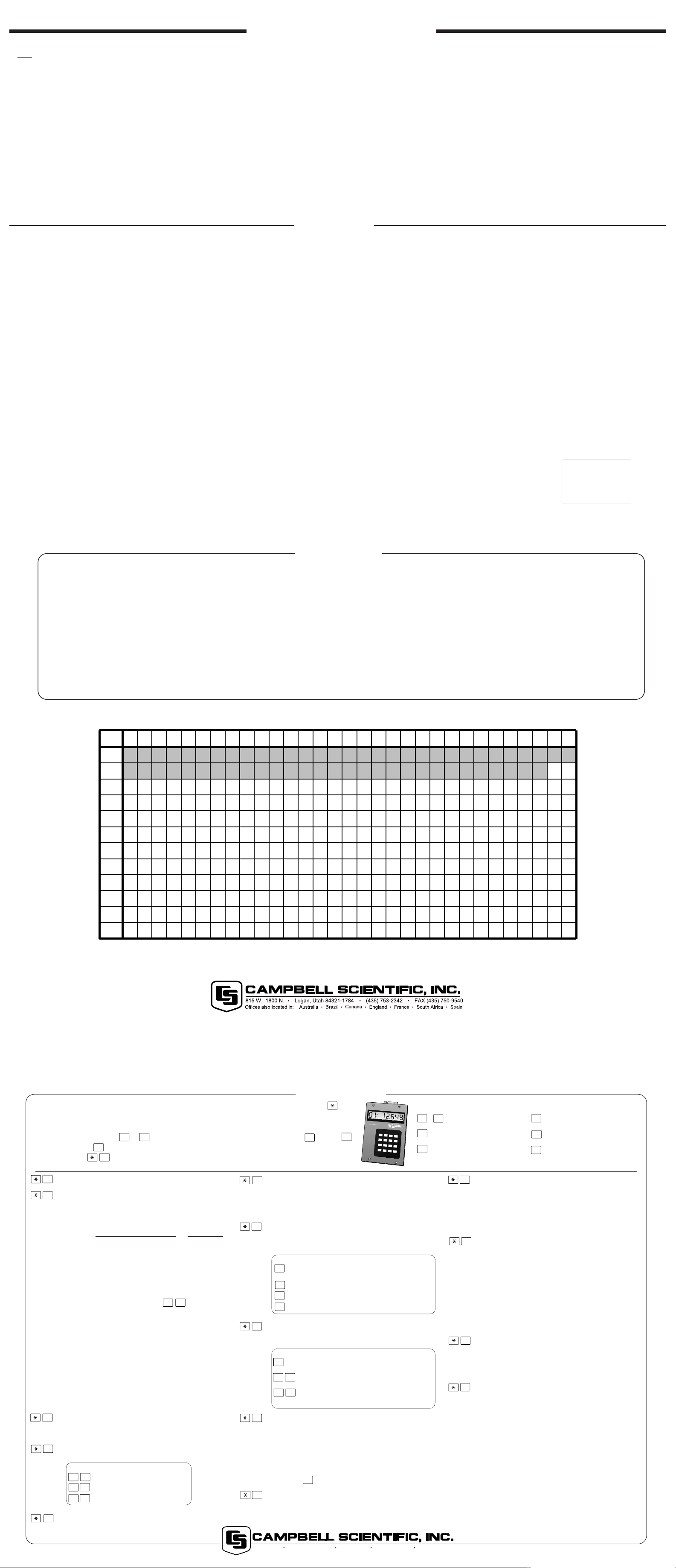
DAY OF YEAR CALENDAR
Add 1 to unshaded values during leap years.
1 2 3 4 5 6 7 8 9 10 11 12 13 14 15 16 17 18 19 20 21 22 23 24 25 26 27 28 29 30 31
1 2 3 4 5 6 7 8 9 10 11 12 13 14 15 16 17 18 19 20 21 22 23 24 25 26 27 28 29 30 31
JAN
32 33 34 35 36 37 38 39 40 41 42 43 44 45 46 47 48 49 50 51 52 53 54 55 56 57 58 59 60
FEB
60 61 62 63 64 65 66 67 68 69 70 71 72 73 74 75 76 77 78 79 80 81 82 83 84 85 86 87 88 89 90
MAR
91 92 93 94 95 96 97 98 99 100 101 102 103 104 105 106 107 108 109 110 111 112 113 114 115 116 117 118 119 120
APR
121 122 123 124 125 126 127 128 129 130 131 132 133 134 135 136 137 138 139 140 141 142 143 144 145 146 147 148 149 150 151
MAY
152 153 154 155 156 157 158 159 160 161 162 163 164 165 166 167 168 169 170 171 172 173 174 175 176 177 178 179 180 181
JUN
182 183 184 185 186 187 188 189 190 191 192 193 194 195 196 197 198 199 200 201 202 203 204 205 206 207 208 209 210 211 212
JUL
213 214 215 216 217 218 219 220 221 222 223 224 225 226 227 228 229 230 231 232 233 234 235 236 237 238 239 240 241 242 243
AUG
244 245 246 247 248 249 250 251 252 253 254 255 256 257 258 259 260 261 262 263 264 265 266 267 268 269 270 271 272 273
SEP
OCT
274 275 276 277 278 279 280 281 282 283 284 285 286 287 288 289 290 291 292 293 294 295 296 297 298 299 300 301 302 303 304
305 306 307 308 309 310 311 312 313 314 315 316 317 318 319 320 321 322 323 324 325 326 327 328 329 330 331 332 333 334
NOV
335 336 337 338 339 340 341 342 343 344 345 346 347 348 349 350 351 352 353 354 355 356 357 358 359 360 361 362 363 364 365
DEC
S
E
R
I
A
L
i
/
0
1
5
6
2
3
4
7
8
9
O
C
R
1
0
K
D
K
E
Y
B
O
A
R
D
D
I
S
P
L
A
Y
1
2
3
A
4
5
6
B
7
8
9
C
0
#
D
*
M
A
D
E
I
N
U
S
A
A
B
C
D
815 W. 1800 N. Logan, Utah 84321-1784 (435) 753-2342 FAX (435) 750-9540 www.campbellsci.com
 Loading...