

Page 1
CNR2 Net Radiometer
Revision: 5/10
Copyright © 2000-2010
Campbell Scientific, Inc.
Page 2
Warranty and Assistance
The CNR2 NET RADIOMETER is warranted by CAMPBELL
SCIENTIFIC, INC. to be free from defects in materials and workmanship
under normal use and service for twelve (12) months from date of shipment
unless specified otherwise. Batteries have no warranty. CAMPBELL
SCIENTIFIC, INC.'s obligation under this warranty is limited to repairing or
replacing (at CAMPBELL SCIENTIFIC, INC.'s option) defective products.
The customer shall assume all costs of removing, reinstalling, and shipping
defective products to CAMPBELL SCIENTIFIC, INC. CAMPBELL
SCIENTIFIC, INC. will return such products by surface carrier prepaid. This
warranty shall not apply to any CAMPBELL SCIENTIFIC, INC. products
which have been subjected to modification, misuse, neglect, accidents of
nature, or shipping damage. This warranty is in lieu of all other warranties,
expressed or implied, including warranties of merchantability or fitness for a
particular purpose. CAMPBELL SCIENTIFIC, INC. is not liable for special,
indirect, incidental, or consequential damages.
Products may not be returned without prior authorization. The following
contact information is for US and International customers residing in countries
served by Campbell Scientific, Inc. directly. Affiliate companies handle
repairs for customers within their territories. Please visit
www.campbellsci.com to determine which Campbell Scientific company
serves your country.
To obtain a Returned Materials Authorization (RMA), contact CAMPBELL
SCIENTIFIC, INC., phone (435) 753-2342. After an applications engineer
determines the nature of the problem, an RMA number will be issued. Please
write this number clearly on the outside of the shipping container.
CAMPBELL SCIENTIFIC's shipping address is:
CAMPBELL SCIENTIFIC, INC.
RMA#_____
815 West 1800 North
Logan, Utah 84321-1784
For all returns, the customer must fill out a “Declaration of Hazardous Material
and Decontamination” form and comply with the requirements specified in it.
The form is available from our website at
completed form must be either emailed to repair@campbellsci.com
435-750-9579. Campbell Scientific will not process any returns until we
receive this form. If the form is not received within three days of product
receipt or is incomplete, the product will be returned to the customer at the
customer’s expense. Campbell Scientific reserves the right to refuse service on
products that were exposed to contaminants that may cause health or safety
concerns for our employees.
www.campbellsci.com/repair
. A
or faxed to
Page 3

CNR2 Table of Contents
PDF viewers note: These page numbers refer to the printed version of this document. Use
the Adobe Acrobat® bookmarks tab for links to specific sections.
1. General Description.....................................................1
2. Sensor Specifications.................................................1
2.1 CNR2 Specifications ................................................................................1
2.2 Pyranometer Specifications......................................................................2
2.3 Pyrgeometer Specifications......................................................................2
3. Installation....................................................................2
4. Using the CNR2 in the Two Separate Components
Mode (2SCM).............................................................5
4.1 Measuring Solar Radiation with the Pyranometers ..................................5
4.2 Measuring Far Infrared Radiation with the Pyrgeometers........................5
4.3 Calculation of the Net Solar Radiation.....................................................6
5. Wiring............................................................................6
6. Datalogger Programming............................................7
6.1 Calibration Factor.....................................................................................8
6.2 Example Programs....................................................................................8
6.2.1 Example Program for CR1000 Datalogger.....................................8
6.2.2 Example Program for CR10X Datalogger......................................9
7. Calibration..................................................................11
8. Maintenance...............................................................12
9. Typical Values............................................................13
Figures
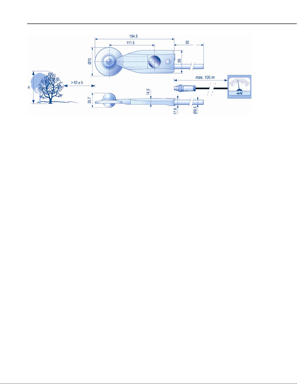
2-1. The Dimensions of the CNR2.................................................................2
3-1. Mounting According to Hemisphere.......................................................3
3-2. The CNR2 mounted to a pole (top) and crossarm (bottom) via
the 26120 Mounting Bracket Kit..........................................................4
5-1. Pin Layout on Campbell Scientific Black Cable.....................................6
5-2. Pin Layout on Kipp & Zonen Original Cable .........................................7
i
Page 4

CNR2 Table of Contents
Tables
8-1. Dirt, Rain, or Snow on CNR2 Sensor will Reduce the Readings......... 12
8-2. CNR2 Net Radiometer Bubble-Level................................................... 13
8-3. Replacing Drying Cartridge.................................................................. 13
5-1. CRBasic Datalogger Connections for Differential Measurement........... 6
5-2. Edlog Datalogger Connections for Differential Measurement............... 7
5-3. Campbell Scientific Cable vs. Kipp & Zonen Cable.............................. 7
9-1. Typical Values from CNR2 Net Radiometer........................................ 13
ii
Page 5

CNR2 Net Radiometer
1. General Description
The CNR2 Net Radiometer is intended for the analysis of the radiation balance
of short-wave and long-wave infrared radiation. The most common application
is the measurement of total net radiation at the earth's surface.
The CNR2 design is such that both the upward facing and the downwardfacing instruments measure the energy that is received from the hemisphere.
The short-wave sensor, or pyranometer, has a field of view of 180 degrees on
the upper and 150 degrees on the lower detector. The long wave sensor, or
pyrgeometer, has a field of view of 150 degrees on the upper and the lower
detector. The output is expressed in Watts per square meter. The total spectral
range that is measured is roughly from 0.3 to 40 micrometers. This spectral
range covers both the solar radiation, 0.3 to 2.8 micrometers, and the far
infrared radiation, 4.5 to 42 micrometers.
The design of the CNR2 is such that short-wave radiation and long-wave
radiation are measured separately. Short-wave radiation is measured by two
pyranometers, one for measuring incoming short-wave radiation from the sky,
and the other, which faces downward, for measuring the reflected short-wave
radiation. The final result from these two pyranometers is net short-wave
radiation.
Long-waveradiation is measured by two pyrgeometers, one for measuring the
long-wave radiation from the sky, the other from the soil surface. Net longwave radiation is a final result of measurements from those two detectors.
Additional information on the CNR2 sensor can be found in the Kipp & Zonen
CNR2 Manual. The primary intent of this manual is to provide information on
interfacing the CNR2 to Campbell Scientific dataloggers.
2. Sensor Specifications
2.1 CNR2 Specifications
Response time: <10s
Temperature dependence of
sensitivity (-10°C to +40°C): <5%
Sensor asymmetry: <5%
Sensitivities: 10 to 20 μV/W/m
Sensitivity change per year: <1%
Tilt error: <1%
Uncertainty in daily total: <10%
Cable length:
Weight:
2
Customer’s choice from 3 to 100 ft.
(Recommended are 50, 75, and 100 ft)
250 g (add about 300g for each
30ft of cable)
1
Page 6
CNR2 Net Radiometer
2.2 Pyranometer Specifications
FIGURE 2-1. The Dimensions of the CNR2
2.3 Pyrgeometer Specifications
3. Installation
Spectral range:
Zero offset: Type A; 200 W/m
2
FIR
Field of view for upper detector:
Field of view for lower detector:
Directional error:
Non-linearity (0-1000 W m
-2
) net
irradiance:
Spectral range:
Field of view of upper detector:
Field of view of lower detector:
Non-linearity (-250 to +250 W m
net irradiance:
310 to 2800 nm
<15 W/m
180°
150°
<20 W m
<2.0%
4.5 to 42 µm
150°
150°
-2
)
<1%
2
-2
2
For measurement of the net radiation, it is important that the instrument is
located in a place that is representative of the entire study region.
Install the CNR2 such that no shadow is cast on the net radiometer at any time
during the day. In the Northern Hemisphere, mount the CNR2 south of the
mast. In the Southern Hemisphere, mount the CNR2 north of the mast (see
Figure 3-1).
Page 7

CNR2 Net Radiometer
FIGURE 3-1. Mounting According to Hemisphere
Mount the CNR2 at a height of at least 1.5 meters above the surface to avoid
the shading effects of the instruments on the soil and to promote spatial
averaging of the measurement. If the instrument is H meters above the surface,
99% of the input of the lower sensors comes from a circular area with a radius
of 10 H. Shadows or surface disturbances with radius <0.1 H will affect the
measurement by less than 1%.
The 26120 mounting bracket kit is used to attach the CNR2 directly to a
vertical pole or to a CM202, CM204, or CM206 crossarm.
NOTE
NOTE
A 26127 mounting rod is required to attach the CNR2 to a pole
or crossarm via the 26120 mounting kit. The 26127 mounting
rod began shipping with the CNR2 in February 2010. This
mounting rod will need to be purchased if the CNR2 was shipped
prior to February 2010.
Mount the sensor as follows:
1. Screw the 26127 mounting rod into the base of the CNR2.
2. Attach the 26120 mounting bracket to the pole or crossarm, using the kit’s
U-bolts (see Figure 3-2).
3. Insert the 26127 mounting rod into the mounting block of the 26120
mounting bracket kit. Make sure the sensor points in the direction of the
arrows that appear after the word “SENSOR” on top of the bracket (see
Figure 3-2). Perform a coarse leveling of the sensor using the bubble level
on the top of the CNR2, and tighten the four screws on top of the
mounting bracket to properly secure the mounting rod so that it does not
rotate.
Do not attempt to rotate the instrument using the sensor heads, or
you may damage the sensor; use the mounting rod only.
4. Perform the fine leveling using the two spring-loaded leveling screws: one
on the front and the other on the back of the bracket.
3
Page 8

CNR2 Net Radiometer
4
FIGURE 3-2. The CNR2 mounted to a pole (top) and
crossarm (bottom) via the 26120 Mounting Bracket Kit.
For installation in buildings or in solar energy applications, users will often
have to mount the CNR2 parallel to the surface that is being studied. This may
be in a tilted or a vertical position. The sensitivity of the radiometers will be
affected, but only in a minor way. This is specified as the so-called tilt effect.
From the specifications, notice that the tilt effect (this is change in sensitivity)
remains within 1%.
Page 9

CNR2 Net Radiometer
m/W
μ
m/W
μ
4. Using the CNR2 in the Two Separate Components Mode (2SCM)
The two pyranometers will measure the short-wave radiation (incoming from
the sky and reflected from the soil surface); the two pyrgeometers will measure
the long-wave radiation (incoming from the sky and reflected from the soil
surface). However, only one output for short-wave radiation (net short-wave)
and one output for long-wave radiation (net long-wave) will be given as a
result of the CNR2 measurements.
4.1 Measuring Solar Radiation with the Pyranometers
The upward-facing pyranometer measures incoming short-wave (global or
solar) radiation. The downward-facing pyranometer measures the reflected
short-wave (solar) radiation. When the final output of the net solar radiation is
made by the sensor, the reflected radiation is subtracted from the global
radiation.
To find the net short-wave radiation, divide the measured short-wave output
from the sensor by its sensitivity.
U
SW
E =
Where, E
U
S
NETSW
is the net short-wave radiation in W m-2
NETSW
is output voltage in µV
SW
is sensitivity in
SW
(4.1)
S
SW
V
2
4.2 Measuring Far Infrared Radiation with the Pyrgeometers
The upward-facing pyrgeometer measures the far infrared radiation from the
sky. The downward-facing pyrgeometer measures the far infrared radiation
that is emitted by the ground.
The long-wave infrared signal output is the difference between incoming and
outgoing infrared radiation.
To find the net long-wave radiation, divide the measured long-wave output
from the sensor by its sensitivity.
U
E = (4.2)
NETLW
LW
S
LW
2
m/W
Where, E
U
S
NETLW
is output voltage in µV
LW
is sensitivity in
LW
is the net long-wave radiation in W m-2
V
2
5
Page 10

CNR2 Net Radiometer
4.3 Calculation of the Net Solar Radiation
5. Wiring
The net radiation, E
, is calculated using the sensor measurement results for
NET
net short-wave radiation and net long-wave radiation. The net radiation is the
difference between the net short-wave and net long-wave radiation.
= E
E
NET
NETSW
+ E
NETLW
The two radiation outputs from CNR2 Net Radiometer can be measured using
differential or single-ended inputs on the datalogger. A differential voltage
measurement (VoltSE instruction in CRBasic or Instruction 2 in Edlog) is
recommended because it has better noise rejection than a single-ended
measurement.
FIGURE 5-1. Pin Layout on Campbell Scientific Black Cable
TABLE 5-1. CRBasic Datalogger
Connections for Differential Measurement
Heat Shrink Label
Color
Pin
Number
CR800/CR850
CR1000/CR3000/CR5000
Pyranometer Sig White 1 Differential Input (H)
Pyranometer Ref Blue 2 Differential Input (L)
Pyrgeometer Sig Brown 3 Differential Input (H)
Pyrgeometer Ref Black 4 Differential Input (L)
Shield Clear
6
Page 11

CNR2 Net Radiometer
TABLE 5-2. Edlog Datalogger Connections for Differential Measurement
Heat Shrink Label Color CR10X, CR510 CR23X 21X/CR7
Pyranometer Sig White Differential Input (H) Differential Input (H) Differential Input (H)
Pyranometer Ref Blue Differential Input (L) Differential Input (L) Differential Input (L)
Pyrgeometer Sig Brown Differential Input (H) Differential Input (H) Differential Input (H)
Pyrgeometer Ref Black Differential Input (L) Differential Input (L) Differential Input (L)
Shield Clear G
If the CNR2 Net Radiometer was purchased from Kipp and Zonen, the color of
the connection cable is yellow and have the pin out shown in Figure 5-2.
FIGURE 5-2. Pin Layout on Kipp & Zonen Original Cable
TABLE 5-3. Campbell Scientific Cable vs. Kipp & Zonen Cable
Campbell Scientific Cable Kipp & Zonen Cable
White Red
Blue Blue
Brown Green
Black Yellow
Clear Clear
6. Datalogger Programming
The CNR2 outputs two voltages that typically range from 0 to 15 mV for the
pyranometers, and ±5 mV for the pyrgeometers. Use a differential voltage
measurement because it has better noise rejection than a single-ended
measurement. If differential channels are not available, single-ended
measurements can be used. The acceptability of a single-ended measurement
7
Page 12

CNR2 Net Radiometer
6.1 Calibration Factor
can be determined by simply comparing the results of single-ended and
differential measurements made under the same conditions.
Each CNR2 is shipped with a ‘Certificate of Calibration’ by the manufacturer
that shows the sensor serial number and ‘sensitivity’, or calibration factor.
The serial number and sensitivity are also shown on a label attached to the
sensor.
-2
The calibration factor is in units of μV/(W m
to units of (W m
-2
)/mV for the multiplier parameter in the datalogger program.
), which needs to be converted
To determine the multiplier, divide the calibration factor into 1000. For
example, if the calibration factor is 22.0 for short-wave radiation and 11.6 for
long-wave radiation, the multipliers are:
-2
Short Wave: 1000/22.0 μV/(W m
) = 45.46 (W m-2)/mV
Long Wave: 1000/11.6 μV/(W m
-2
) = 86.21 (W m-2)/mV
6.2 Example Programs
6.2.1 Example Program for CR1000 Datalogger
'CNR2 Net Radiometer program for CR1000 datalogger
'*** Wiring ***
'1H Short wave signal (white)
'1L Short wave signal reference (blue)
'2H Long wave signal (brown)
'2L Long wave signal reference (black)
'gnd Shield (clear)
‘Declare Constants
Const CNR2_SW_CAL = 45.46 'Unique multiplier for CNR 2 net SW radiation (1000/sensitivity).
Const CNR2_LW_CAL = 86.21 'Unique multiplier for CNR 2 net LW radiation (1000/sensitivity).
'Declare Variables and Units
Public Net_Shortwave
Public Net_Longwave
Public Net_Rad
Units Net_Shortwave=Wm-2
Units Net_Longwave=Wm-2
Units Net_Rad=Wm-2
'Define Data Tables
DataTable(Table1,True,-1)
DataInterval(0,60,Min,10)
Minimum(1,Net_Shortwave,IEEE4,False,True)
Maximum(1,Net_Shortwave, IEEE4,False,True)
Average(1,Net_Shortwave, IEEE4,False)
8
Page 13

Minimum(1,Net_Longwave, IEEE4,False,True)
Maximum(1,Net_Longwave, IEEE4,False,True)
Average(1,Net_Longwave, IEEE4,False)
Average(1,Net_Rad, IEEE4,False)
EndTable
'Main Program
BeginProg
Scan(1,Sec,1,0)
'CNR2 Net Radiation Measurements
VoltDiff(Net_Shortwave,1,mV25,1,True,200,250, CNR2_SW_CAL,0.0)
VoltDiff(Net_Longwave,1,mV25,2,True,0,250, CNR2_LW_CAL,0.0)
Net_Rad = Net_Shortwave+Net_Longwave
'Call Data Tables and Store Data
CallTable(Table1)
NextScan
EndProg
6.2.2 Example Program for CR10X Datalogger
CNR2 Net Radiometer
;CNR2 Net Radiometer program for CR10X datalogger
;*** Wiring ***
; 1H Shortwave signal (white)
; 1L Shortwave signal reference (blue)
; 2H Longwave signal (brown)
; 2L Longwave signalreference- (black)
;gnd Shiled (clear)
;
;*** Wiring ***
; 1H Shortwave signal (white)
; 1L Shortwave signal reference (blue)
;gnd
; 2H Longwave signal (brown)
; 2L Longwave signal reference (black)
;gnd Shield (clear)
;
*Table 1 Program
01: 1.0000 Execution Interval (seconds)
; Measure Net Shortwave Radiation
1: Volt (Diff) (P2)
1: 1 Reps
2: 23 25 mV 60 Hz Rejection Range
3: 1 DIFF Channel
4: 1 Loc [ Net_SW ]
5: 45.46 Multiplier
6: 0.0 Offset
9
Page 14

CNR2 Net Radiometer
; Measure Net Longwave Radiation
2: Volt (Diff) (P2)
1: 1 Reps
2: 22 7.5 mV 60 Hz Rejection Range
3: 2 DIFF Channel
4: 2 Loc [ Net_LW ]
5: 86.21 Multiplier
6: 0.0 Offset
;
;Measure Net Radiation
3: Z=X+Y (P33)
1: 1 X Loc [ Net_SW ]
2: 2 Y Loc [ Net_LW ]
3: 3 Z Loc [ Net_Rad ]
;Output data to the final storage every 60 minutes
;
4: If time is (P92)
1: 0 Minutes (Seconds --) into a
2: 60 Interval (same units as above)
3: 10 Set Output Flag High (Flag 0)
5: Set Active Storage Area (P80)^2826
1: 1 Final Storage Area 1
2: 102 Array ID
6: Real Time (P77)^11314
1: 1220 Year,Day,Hour/Minute (midnight = 2400)
7: Minimum (P74)^13722
1: 1 Reps
2: 10 Value with Hr-Min
3: 1 Loc [ Net_SW ]
8: Maximum (P73)^10217
1: 1 Reps
2: 10 Value with Hr-Min
3: 1 Loc [ Net_SW ]
9: Average (P71)^10475
1: 1 Reps
2: 1 Loc [ Net_SW ]
10: Minimum (P74)^11228
1: 1 Reps
2: 10 Value with Hr-Min
3: 2 Loc [ Net_LW ]
11: Maximum (P73)^17442
1: 1 Reps
2: 10 Value with Hr-Min
3: 2 Loc [ Net_LW ]
10
Page 15

12: Average (P71)^29073
1: 1 Reps
2: 2 Loc [ Net_LW ]
13: Average (P71)^15174
1: 1 Reps
2: 3 Loc [ Net_Rad ]
*Table 2 Program
01: 10.0000 Execution Interval (seconds)
1: Serial Out (P96)
1: 71 Storage Module
*Table 3 Subroutines
End Program
7. Calibration
CNR2 Net Radiometer
Recalibrate the CNR2 every two years, or as an alternative, by running a higher
standard next to it. Compare the pyranometers over a two-day period when the
days are clear. Compare the pyrgeometers during the night. Deviations of
more than 6% can be used to correct the calibration factors.
11
Page 16

CNR2 Net Radiometer
8. Maintenance
Clean domes and windows with distilled water or alcohol. Readings are
reduced if domes and/or windows are not clean.
FIGURE 8-1. Dirt, Rain or Snow on CNR2 Sensors will Reduce the Readings
12
Page 17

CNR2 Net Radiometer
Keep instrument leveled at all times during the measurements.
FIGURE 8-2. CNR2 Net Radiometer Bubble-Level
Replace drying cartridge every 6 months.
9. Typical Values
Wavelength Fully Clouded Sunny, Partly Clouded Clear and Sunny
Net short wave 0 to 120 W/m² 50 to 500 W/m² 200 to 1000 W/m²
Net long wave –25 to +25 W/m² –50 to +50 W/m² –50 to –200 W/m²
FIGURE 8-3. Replacing Drying Cartridge
(first replacement cartridge comes with the CNR2)
TABLE 9-1. Typical Values from CNR2 Net Radiometer
13
Page 18

CNR2 Net Radiometer
14
Page 19

Page 20

Campbell Scientific Companies
Campbell Scientific, Inc. (CSI)
815 West 1800 North
Logan, Utah 84321
UNITED STATES
www.campbellsci.com • info@campbellsci.com
Campbell Scientific Africa Pty. Ltd. (CSAf)
PO Box 2450
Somerset West 7129
SOUTH AFRICA
www.csafrica.co.za • cleroux@csafrica.co.za
Campbell Scientific Australia Pty. Ltd. (CSA)
PO Box 444
Thuringowa Central
QLD 4812 AUSTRALIA
www.campbellsci.com.au • info@campbellsci.com.au
Campbell Scientific do Brazil Ltda. (CSB)
Rua Luisa Crapsi Orsi, 15 Butantã
CEP: 005543-000 São Paulo SP BRAZIL
www.campbellsci.com.br • suporte@campbellsci.com.br
Campbell Scientific Canada Corp. (CSC)
11564 - 149th Street NW
Edmonton, Alberta T5M 1W7
CANADA
www.campbellsci.ca • dataloggers@campbellsci.ca
Campbell Scientific Centro Caribe S.A. (CSCC)
300 N Cementerio, Edificio Breller
Santo Domingo, Heredia 40305
COSTA RICA
www.campbellsci.cc • info@campbellsci.cc
Campbell Scientific Ltd. (CSL)
Campbell Park
80 Hathern Road
Shepshed, Loughborough LE12 9GX
UNITED KINGDOM
www.campbellsci.co.uk • sales@campbellsci.co.uk
Campbell Scientific Ltd. (France)
Miniparc du Verger - Bat. H
1, rue de Terre Neuve - Les Ulis
91967 COURTABOEUF CEDEX
FRANCE
www.campbellsci.fr • info@campbellsci.fr
Campbell Scientific Spain, S. L.
Avda. Pompeu Fabra 7-9, local 1
08024 Barcelona
SPAIN
www.campbellsci.es • info@campbellsci.es
Please visit www.campbellsci.com to obtain contact information for your local US or International representative.
 Loading...