

Page 1
CM106K Tripod
Revision: 3/12
Copyright © 2011-2012
Campbell Scientific, Inc.
Page 2

Page 3

Warranty
“PRODUCTS MANUFACTURED BY CAMPBELL SCIENTIFIC, INC. are
warranted by Campbell Scientific, Inc. (“Campbell”) to be free from defects in
materials and workmanship under normal use and service for twelve (12)
months from date of shipment unless otherwise specified in the corresponding
Campbell pricelist or product manual. Products not manufactured, but that are
re-sold by Campbell, are warranted only to the limits extended by the original
manufacturer. Batteries, fine-wire thermocouples, desiccant, and other
consumables have no warranty. Campbell's obligation under this warranty is
limited to repairing or replacing (at Campbell's option) defective products,
which shall be the sole and exclusive remedy under this warranty. The
customer shall assume all costs of removing, reinstalling, and shipping
defective products to Campbell. Campbell will return such products by surface
carrier prepaid within the continental United States of America. To all other
locations, Campbell will return such products best way CIP (Port of Entry)
INCOTERM® 2010, prepaid. This warranty shall not apply to any products
which have been subjected to modification, misuse, neglect, improper service,
accidents of nature, or shipping damage. This warranty is in lieu of all other
warranties, expressed or implied. The warranty for installation services
performed by Campbell such as programming to customer specifications,
electrical connections to products manufactured by Campbell, and product
specific training, is part of Campbell’s product warranty. CAMPBELL
EXPRESSLY DISCLAIMS AND EXCLUDES ANY IMPLIED
WARRANTIES OF MERCHANTABILITY OR FITNESS FOR A
PARTICULAR PURPOSE. Campbell is not liable for any special, indirect,
incidental, and/or consequential damages.”
Page 4

Assistance
Products may not be returned without prior authorization. The following
contact information is for US and international customers residing in countries
served by Campbell Scientific, Inc. directly. Affiliate companies handle
repairs for customers within their territories. Please visit
www.campbellsci.com to determine which Campbell Scientific company serves
your country.
To obtain a Returned Materials Authorization (RMA), contact CAMPBELL
SCIENTIFIC, INC., phone (435) 227-9000. After an applications engineer
determines the nature of the problem, an RMA number will be issued. Please
write this number clearly on the outside of the shipping container. Campbell
Scientific's shipping address is:
CAMPBELL SCIENTIFIC, INC.
RMA#_____
815 West 1800 North
Logan, Utah 84321-1784
For all returns, the customer must fill out a "Statement of Product Cleanliness
and Decontamination" form and comply with the requirements specified in it.
The form is available from our web site at www.campbellsci.com/repair. A
completed form must be either emailed to repair@campbellsci.com or faxed to
(435) 227-9106. Campbell Scientific is unable to process any returns until we
receive this form. If the form is not received within three days of product
receipt or is incomplete, the product will be returned to the customer at the
customer's expense. Campbell Scientific reserves the right to refuse service on
products that were exposed to contaminants that may cause health or safety
concerns for our employees.
Page 5

CM106K Table of Contents
PDF viewers: These page numbers refer to the printed version of this document. Use the
PDF reader bookmarks tab for links to specific sections.
1. Cautionary Statements................................................1
1.1 Site Selection ............................................................................................1
1.2 Tripod Mounting.......................................................................................1
1.3 Tripod Installation ....................................................................................1
2. Tripod Installation........................................................2
2.1 Tripod Base Assembly..............................................................................2
2.1.1 Parts List .........................................................................................2
2.1.2 Leg Assembly .................................................................................3
2.2 Tripod Base Positioning ...........................................................................6
2.2.1 Mounting on a Relatively Flat Area................................................7
2.2.2 Mounting on an Incline...................................................................7
2.3 Mast ..........................................................................................................8
2.4 Installing the Optional Guy Kit ................................................................9
2.5 Staking the Tripod Feet ..........................................................................11
2.6 Tripod Grounding...................................................................................12
2.7 Crossarm Attachment .............................................................................14
2.8 Enclosure Attachment.............................................................................14
2.8.1 Enclosure Mounting to Tripod Mast.............................................14
2.8.2 Enclosure Mounting to Tripod Leg...............................................15
3. General .......................................................................17
4. Specifications ............................................................18
5. Tools List (for tripod, mast, enclosures, and
crossarms) ...............................................................18
6. Tripod Components................................................... 19
7. Mounting Brackets ....................................................19
7.1 CM210 Crossarm Mounting Kit.............................................................19
7.2 CM216 Mast Mounting Kit ....................................................................20
7.3 CM220 Right Angle Mounting Kit.........................................................21
7.4 CM225 and 18098 Pyranometer Mounting Stand ..................................22
7.5 CM230 Adjustable Angle Mounting Kit ................................................23
7.6 CM235 Magnetic Mounting Stand .........................................................24
7.7 RM Young Gill Radiation Shields..........................................................25
i
Page 6

CM106K Table of Contents
Figures
2-1. Tripod component dimensions ............................................................... 3
2-2. Comparison of one leg pointing downhill (right) versus two legs
pointing downhill ................................................................................ 7
2-3. Guy collar ............................................................................................... 9
2-4. Anchor attachment................................................................................ 10
2-5. Staking the tripod feet........................................................................... 11
2-6. Ground rod and clamp .......................................................................... 12
2-7. Lightning rod and tripod grounding lug ............................................... 13
2-8. CM204 Crossarm.................................................................................. 14
2-9. Enclosure with the –MM Bracket......................................................... 15
2-10. Enclosure with the –LM Bracket........................................................ 16
3-1. Typical tripod-based weather station.................................................... 17
7-1. CM210 Crossarm Mounting Kit (shown with user-supplied pipe) ...... 19
7-2. CM216 Mast Mounting Kit .................................................................. 20
7-3. CM220 Right Angle Mounting Kit....................................................... 21
7-4. CM225 Pyranometer Mounting Stand.................................................. 22
7-5. CM230 Adjustable Angle Mounting Kit .............................................. 23
7-6. CM235 Magnetic Mounting Stand ....................................................... 24
7-7. RM Young Gill Radiation Shield ......................................................... 25
ii
Page 7

CM106K Tripod
1. Cautionary Statements
1.1 Site Selection
• Select a safe site to install the tripod.
• The distance between any power lines and the installation site should be at
least one and one-half times the height of the tripod. Make the distance
even greater, if at all possible. Since all overhead power lines look
somewhat alike, consider them all dangerous and stay well away from
them.
• If you have power lines or buried utilities in the area, call your local utility
providers for assistance.
1.2 Tripod Mounting
• NEVER work alone; always have someone near who can summon help.
• Certain clothing may provide a degree of safety, but don't depend on it for
your life (rubber boots or shoes, industrial rubber gloves and a long sleeve
shirt or jacket).
• Check weather conditions. Be sure that it hasn't rained recently and that
the ground is not wet or muddy. Make sure that rain or thunderstorms are
not predicted for the day you decide to install the tripod.
• The wind can blow the tripod into a nearby power line. Don't install or
remove tripods in moderate or heavy winds.
• If you need to use a ladder, make sure it is made of non-conductive (non-
metallic) material. (This is a safety rule that you should follow whenever
you're working with electrical equipment.)
• If possible, have someone present who has been trained in electric shock
first aid.
1.3 Tripod Installation
• Properly assemble the tripod according to instructions (do this where the
tripod is to be put up).
• Once the tripod is up in full vertical position, securely fasten it to the
ground using ground spikes. For situations where soil structure is
questionable or the tripod may experience high wind loads, concrete
footings for the tripod feet and guy anchors should be considered.
• Ground the tripod according to the National Electrical Code.
1
Page 8

CM106K Tripod
2. Tripod Installation
2.1 Tripod Base Assembly
2.1.1 Parts List
Part # Description Qty
10838 Tripod Foot 3
27392 CM106K Body 3
19308 Spacer 6
4366 5/16” Lock Washer 6
19175 5/16-18x2.25” Bolt 6
18126 5/16-18 Bronze Nut 6
19031 Grounding Clamp 2
27113 #10-32 x 0.75” Bolt 4
1201 Clamp Bracket 3
75 5/16-18 x 0.75” Bolt 3
795 ¼-20 Nylock Nut 6
794 ¼-20 x 1.75” Bolt 12
850 CM10 Lightning Rod 1
17589 Lightning Rod Clamp Assembly 1
2
Page 9
2.1.2 Leg Assembly
Leg Brace (3required)
Leg (3 required)
CM106K Tripod
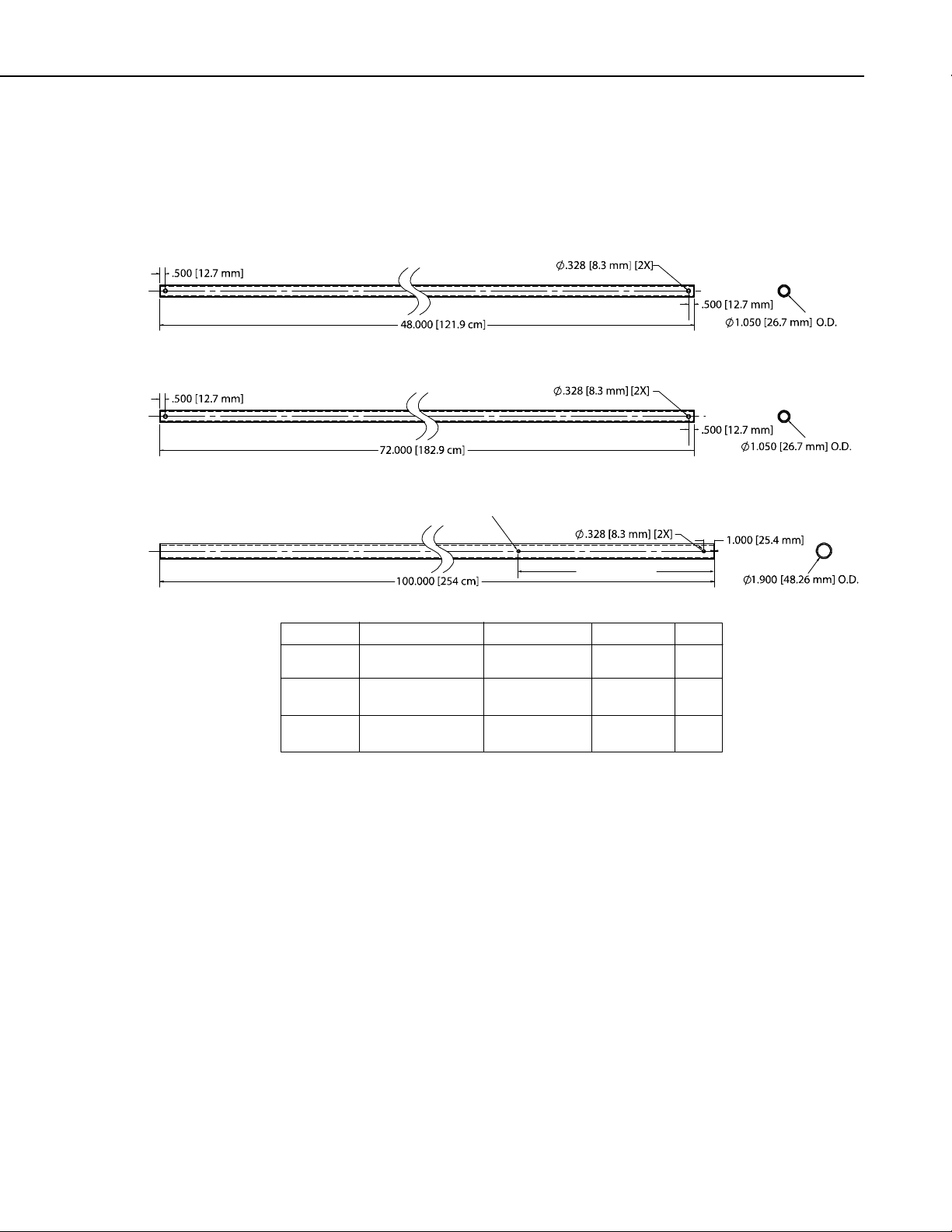
1. Refer to Figure 2-1 to create the following parts:
• Three (3) Leg Braces
• Three (3) Legs
• One (1) Mast
Mast (1 required)
Leg Brace
Leg
Mast
Optional for Guy Kit
20.00 [50.8 cm]
Material
3/4 NPS SCH40
[DN 20 mm]
3/4 NPS SCH40
[DN 20 mm]
11/2NPSSCH40
[DN 40 mm]
Wall Thickness
0.113”
[2.87 mm]
0.113”
[2.87 mm]
0.145”
[3.683 mm]
Length
48.0”
[121.9 cm]
72.0”
[182.9 cm]
100.0”
[254 cm]
Mast and mast legs must be made of Steel
(Minimum yield Strength of 36 ksi [248 MPa])
FIGURE 2-1. Tripod component dimensions
QTY
3
3
1
3
Page 10
CM106K Tripod
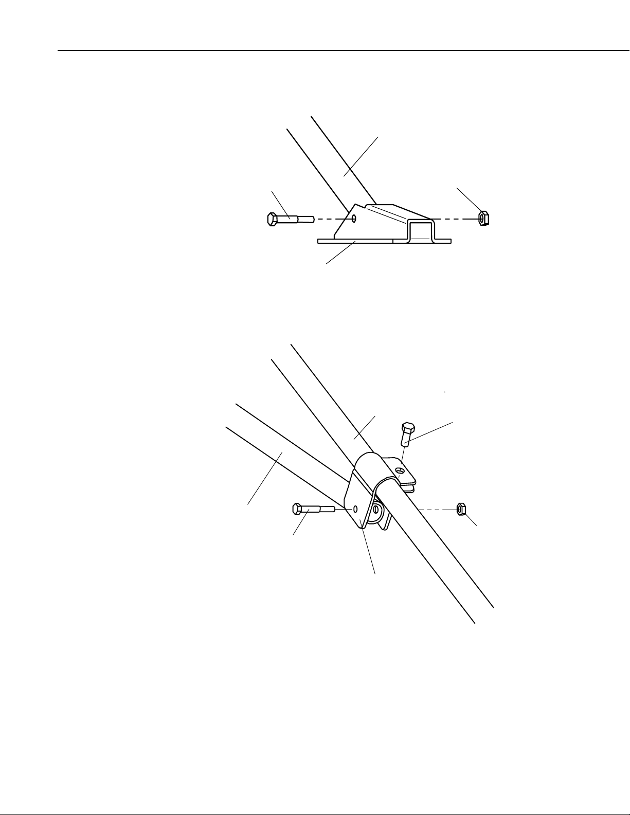
Using a ¼-20 x 1.75” bolt and ½-20 nylock nut, attach a foot to each
2.
tripod leg (Figure 2-2).
Leg
1/4-20 x 1.75” Bolt
1/4-20 Nylock Nut
Foot
Slide a clamp bracket onto each leg. Thread a 5/16-18 x 0.75” bolt into the
3.
bracket, leaving the bracket free to move. Attach a leg brace to each clamp
bracket using a ¼-20 x 1.75” bolt and nylock nut.
Leg
5/16-18 x 0.75” Bolt
4
Leg Brace
1/4-20 Nylock Nut
1/4-20 x 1.75” Bolt
Clamp Bracket
Page 11
CM106K Tripod
Pass a 5/16-18 x 2.25” bolt through a mounting hole in one of the tripod
4.
body pieces as shown. Slide a spacer over the bolt. Place a second tripod
body piece over the end of the bolt, followed by a 5/16 lock washer. Hand
tighten a 5/16-18 bronze nut on the end of the bolt. Repeat this process
with the other five 5/16-18 x 2.25” bolts to assemble the tripod body.
Top V ie w
Tripod Body
Spacer
Spacer
5/16 Lock Washer
5/16-18 x 2.25” Bolt
Tripod Body
5/16-18 x 2.25” Bolt
5/16-18 Bronze Nut
5/16 Lock Washer
5/16-18 Bronze Nut
Spacer
5
Page 12

CM106K Tripod
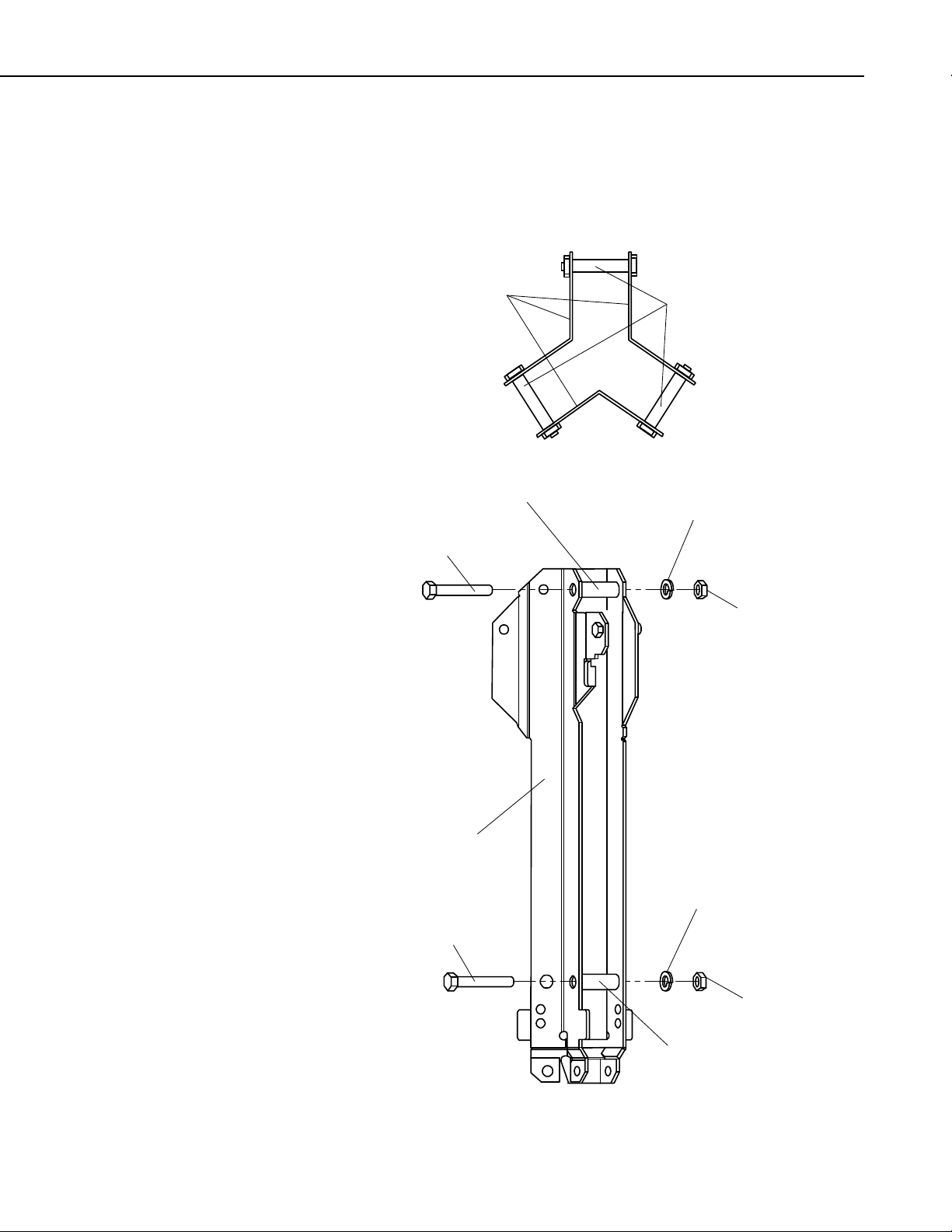
1/4-20 x 1.75” Bolt
Attach each leg assembly to the tripod body using two ¼-20 x 1.75” bolts
5.
and nylock nuts. Attach the two grounding clamps using #10-32 x 0.75”
bolts. Do not over-tighten the bolts. The tripod legs and leg braces must be
able to pivot.
1/4-20 Nylock Nut
Leg
Tripod Body
Grounding Clamp
#10-32 x 0.75” Bolt
1/4-20 x 1.75” Bolt
Leg Brace
2.2 Tripod Base Positioning
Leg
Grounding Clamp
#10-32 x 0.75” Bolt
1/4-20 Nylock Nut
6
WARNING
Tripod installation near power lines is dangerous. The
minimum safe recommended distance from overhead
power lines is 1½ times the height of the tripod and
mast combined. Call your local utility providers to
locate buried utilities prior to installation.
The tripod base has three legs, which are individually adjustable, that allow the
tripod to be installed over non-level terrain.
Page 13

Prepare the area where the tripod will be installed. The tripod requires an area
approximately 11 ft (3.4 m) in diameter. Natural vegetation and the ground
surface should be disturbed as little as possible, but brush and tall weeds should
be removed.
Stand the tripod base up on end, and rotate the feet perpendicular to the legs.
Each leg has a clamp bracket with a bolt that locks the leg in place when
tightened.
2.2.1 Mounting on a Relatively Flat Area
Loosen one clamp bracket bolt at a time and extend each leg until the three legs
are at the same extension. With the legs extended, orient the tripod so that one
of the legs points South (assuming the instrument enclosure with -MM Mast
Mount bracket will face North). If the instrument enclosure has the -LM Leg
Mount bracket, orient the tripod so that the enclosure will mount to one of the
three leg mount positions on the tripod, facing the desired direction. The tripod
is typically plumbed after the mast has been installed, as described in Section
2.3.
2.2.2 Mounting on an Incline
Loosen the bolts on the clamp brackets. With the legs extended, orient the
tripod so that one leg points downhill and the other two legs point uphill. The
tripod is more stable with only one leg pointed downhill because the mast is
closer to the center of the footprint (see Figure 2-2). Tighten the bolts on the
clamp brackets to lock the legs in place.
CM106K Tripod
The tripod is typically plumbed after the mast has been installed, as described
in Section 2.3.
[3.4m]
[3.4m]
Ø132in
One Foot Downhill
ForBetterStability
GRADE = 100% * (RISE/RUN) = 100% * tan(angle)
Ø132in
GRADE
FIGURE 2-2. Comparison of one leg pointing downhill (right) versus
two legs pointing downhill
7
Page 14

CM106K Tripod
2.3 Mast
Slide the mast into the tripod base orienting the end with the hole upwards,
making sure that it extends below the lower bolts and rests on the tripod body
tabs. Tighten the six 5/16-18 x 2.25” bolts to secure the mast.
Plumb the tripod by adjusting the northeast and south facing legs (use the
downhill leg and one of the uphill legs when the tripod is installed on a slope).
With a level on the East side of the mast, adjust the Northeast leg for plumb.
With the level on the South side of the mast, adjust the South leg for plumb.
Tighten the 5/16 bolt on each clamp bracket after the adjustments have been
made.
8
Page 15

2.4 Installing the Optional Guy Kit
PN 27117 CM106 Guy Kit can be ordered separately for areas that experience
high wind speeds (Section 4). Install the guy bracket to the mast as shown in
Figure 2-3. Attach the three guy wires to the guy collar and slide the collar over
the mast so that the collar butts against the bracket.
CM106K Tripod
Guy Collar
Guy Wire
Guy Bracket
FIGURE 2-3. Guy collar
On the end of each guy line is a case and hardware to attach to the turnbuckles.
Unscrew the turnbuckles so that only 1/2 in of thread extends beyond the inside
of the turnbuckle body. Attach the case and turnbuckle to secured earth anchors
such as those shown in Fig 2-4. For best results, secure the earth anchors in the
ground at the same angle the guy wires will be attached. Loosen the Phillips
screw, and remove the slack in the guy line by feeding the load end of the guy
wire through the wedge while pulling up on the dead end. If the load end of
the guy wire can’t be fed through the case, use a small flat screwdriver to push
the wedge forward into the case to disengage wedge.
After the slack has been removed from the guy lines, tighten the Phillips
screws and tighten the turnbuckles to tension each guy line to approximately
100 lbf [45 kgf].
9
Page 16

CM106K Tripod
Duckbill Style
Earth Anchor
Auger Style
Earth Anchor
Wedge
10
Phillips Screw
FIGURE 2-4. Anchor attachment
Page 17

2.5 Staking the Tripod Feet
For additional stability, the tripod can be staked to the ground using (3) PN
17049 ground spikes, or secured with user-supplied anchors through the holes
in the feet. Drive the spike at an angle through the hole in each foot.
Spikes may not be adequate depending on soil structure, maximum wind
speeds experienced at the site, mast height, or wind load from the
instrumentation. For questionable situations, concrete footings for the tripod
feet and guy anchors should be considered.
CM106K Tripod
FIGURE 2-5. Staking the tripod feet
11
Page 18

CM106K Tripod
2.6 Tripod Grounding
The tripod must be properly grounded using a user-supplied grounding rod.
Place the clamp over the ground rod and drive the rod (close to the center of
the tripod) using a sledge hammer or fence post driver. Strip 1/2” [12.7 mm]
inch of insulation from both ends of a 4 AWG ground wire. Insert one end of
the ground wire between the clamp and ground rod and tighten the bolt on the
clamp. Attach the other end of the ground wire to the lug on the tripod base as
shown in Figure 2-6.
Ground Lug
Ground Wire
FIGURE 2-6. Ground rod and clamp
Enclosure Ground Wire
Enclosure Ground Lug
12
Strip 1/2” [12.7 mm] of insulation from the ends of a 12 AWG wire. Attach
one end of the wire to the tripod ground lug, and the other end to the enclosure
ground lug as shown in Figure 2-6.
Page 19

CM106K Tripod
Mount the lightning rod and clamp to the tripod mast with pointed tip up, and
notch at bottom, as shown in Figure 2-7.
FIGURE 2-7. Lightning rod and tripod grounding lug
13
Page 20

CM106K Tripod
2.7 Crossarm Attachment
Attach the CM202 (2 ft, 0.6m), CM204 (4 ft, 1.2m), or CM206 (6 ft, 1.8m)
crossarm to the tripod mast as shown in Figure 2-8. For wind sensors, the
crossarm should be approximately 103 inches above the ground. Typically the
crossarm is oriented East/West for wind sensors, North/South for
pyranometers.
FIGURE 2-8. CM204 Crossarm
2.8 Enclosure Attachment
The ENC 10/12, ENC 12/14, ENC 14/16, and ENC 16/18 enclosures can be
ordered with mounting brackets for the CM106K tripod. All enclosure models
can be mounted to the tripod mast (above the legs) with the –MM Mast Mount
bracket option. All enclosure models except the ENC 16/18 can be mounted to
the tripod base and leg with the –LM Leg Mount bracket option.
2.8.1 Enclosure Mounting to Tripod Mast
An enclosure ordered with the –MM bracket has a three-piece top and bottom
brackets with a U-bolt for each bracket.
Attach an enclosure with the –MM mounting bracket to the tripod mast as
follows:
Remove the U-bolts washers and nuts from the brackets.
CM200 Series
Crossarm
Tripod Mast
14
Position the enclosure against the tripod’s mast (North side recommended).
Install the U-bolts, flat washers, lock washers, and nuts. Tighten the nuts until
the lock washers are compressed.
Page 21

CM106K Tripod
–
Route the 14 AWG wire from the grounding lug on the bottom side of the
enclosure to the grounding lug on the base of the tripod (Figure 2-6). Strip
1/2” [12.7 mm] of insulation from each end of the wire. Insert wire ends into
the grounding lugs and tighten.
U-Bolt
MM Bracket
FIGURE 2-9. Enclosure with the –MM Bracket
2.8.2 Enclosure Mounting to Tripod Leg
An enclosure ordered with the –LM bracket has a bracket on each side of the
enclosure, and a U-bolt bracket for securing the enclosure to a tripod leg.
Attach an enclosure with the –LM mounting bracket to the tripod base as
follows:
Slide the keyhole notch in upper corner of the -LM bracket over the hook
located on the tripod base as shown in Figure 2-10, and engage the notch in the
lower corner of the -LM bracket with the enclosure tab.
Remove the washers, nuts and U-bolt from the U-bolt bracket. Install the
bracket as shown in Figure 2-10 (bottom) with the U-bolt capturing the tripod
leg. Tighten the nuts on the U-bolt until the lock washers are compressed.
15
Page 22

CM106K Tripod
Route the 14 AWG wire from the grounding lug on the bottom side of the
enclosure to the grounding lug on the base of the tripod (Figure 2-6). Strip 1/2”
of insulation from each end of the wire. Insert wire ends into the grounding
lugs and tighten.
16
FIGURE 2-10. Enclosure with the –LM Bracket
Page 23

3. General
CM106K Tripod
The CM106K is a general purpose tripod that can be used for mounting
sensors, solar panels, antennas, and instrument enclosures. The CM106K is
constructed from galvanized steel, with individually adjustable legs that allow
installation over uneven terrain. Height of the mast is 10 ft (3m).
The CM106K includes the tripod body, feet, brackets, grounding clamps,
lightning rod, and mounting hardware. The remaining tripod components are
user-supplied (see Section 2 for part specifications).
An optional guy kit is recommended for sites that experience high wind speeds
(see Section 4, Allowable Wind Speed Specifications). Instrument enclosures
can be purchased with mounting brackets that attach to either the mast or leg
section as shown in Section 2.8.
The CM106K can be used for a variety of applications. For meteorological
stations, sensors are mounted to the tripod using mounting brackets appropriate
for the model of sensor. For non-meteorological applications the tripod can be
used to mount instrument enclosures, solar panels, junction boxes, or antennas.
FIGURE 3-1. Typical tripod-based weather station
17
Page 24

CM106K Tripod
4. Specifications
Measurement Height: 10 ft (3.0 m)
Vertical Load Limit: 100 lb (45 kg)
Mast Outer Diameter: 1.90 in. (48 mm)
Base Diameter: 11 ft (3.4 m)
Leveling Adjustment: Clamp brackets on each leg, adjust individually
Leg Base: 6 in. by 3.5 in. with one 0.84 in. hole for stakes
Portability: Collapsible to 9 in. diameter by 100 in (230
Weight with Mast: 67 lb (30 kg)
Allowable Wind Speeds*
(150 x 89 mm with one 21 mm hole for stakes)
mm x 2.54 m) length
Tripod Configuration Sustained Wind Wind Gust
Unguyed 80 mph (36 m/s) 104 mph (46 m/s)
Guyed 115 mph (51 m/s) 150 mph (67 m/s)
*Allowable wind speed values assume:
Mast and leg components are made of steel (minimum yield
•
strength of 36 ksi[248 MPa])and fabricated according to the
specified design
14 x 16 in. enclosure at mast base
•
10.5 x 16.5 in. solar panel at mast base
•
Crossarm and sensors (1.4 ft
•
Adequate ground anchors (stakes can pull out at lower wind
•
speeds)
2
projected area) at mast top
5. Tools List (for tripod, mast, enclosures, and crossarms)
1/2” and 7/16” open end wrenches
adjustable wrench
Phillips head screw drivers (medium, small)
Straight bit screwdrivers (large, medium)
12” torpedo level
side-cut pliers
pencil
tape measure
compass and site declination angle
shovel
sledge hammer (for driving ground rod and stakes)
step ladder
18
Page 25

6. Tripod Components
The tripod body is packaged with the lightning rod. The optional guy kit is
packaged separately.
7. Mounting Brackets
Mounting brackets covered in this section have U-bolts that attach to vertical
and/or horizontal pipes with the following ranges of outside diameters:
inches mm Nominal Pipe Size (inches)
1.5” U-bolt 1.0 – 1.5 25.4 – 38.1 ¾ – 1
2” U-bolt 1.3 – 2.1 33.0 – 53.3 1 – 1 ½
CM106K Tripod
2” U-bolt
with plastic V-block
Some of the brackets (e.g. the CM210) include 1.5” and 2” U-bolts to extend
the range of pipe diameters that the bracket can accommodate. Brackets with
holes for a 1.5” U-bolt will accept a user-supplied 1.75” U-bolt.
1.0 – 2.1 25.4 – 53.3 ¾ – 1 ½
7.1 CM210 Crossarm Mounting Kit
CM200 series crossarms include a CM210 bracket as shown in Figure 7-1.
The CM210 can be ordered separately to attach a user-supplied pipe (1.0 –
1.5” OD) to a mast or tower leg (1.0 – 2.1” OD), or to attach a crossarm to two
tower legs.
CM210
FIGURE 7-1. CM210 Crossarm Mounting Kit (shown with user-supplied
pipe)
19
Page 26

CM106K Tripod
7.2 CM216 Mast Mounting Kit
The CM216 attaches to the top of the mast, and provides a 3/4” or 1” mounting
pipe (1.05” or 1.32” OD) that extends 4” above the mast, as shown in Figure
7-2.
CM216
FIGURE 7-2. CM216 Mast Mounting Kit
20
Page 27

7.3 CM220 Right Angle Mounting Kit
The CM220 attaches a vertical pipe (1.0 – 1.5” OD) to the CM200 series
crossarms or horizontal pipe (1.0 – 1.5” OD) as shown in Figure 7-3.
CM106K Tripod
CM220
CM220
FIGURE 7-3. CM220 Right Angle Mounting Kit
21
Page 28

CM106K Tripod
7.4 CM225 and 18098 Pyranometer Mounting Stand
The CM225 is used to attach a pyranometer or quantum sensor to a horizontal
pipe (1.0 to 2.1” OD) or vertical pole (1.0 to 2.1” OD).
The LI200X pyranometer and LI190SB quantum sensor mount to the CM225
via the LI200S leveling base (see Figure 7-4). The CS300 pyranometer mounts
to the CM225 via the 18356 leveling base. The CMP3 and LP02 pyranometers
include their own bubble level and leveling screws allowing them to mount
directly to the CM225.
The 18098 provides a larger surface for mounting a user-supplied Eppley
pyranometer.
CM225
LI2003S
LI200X Pyranometer
CM225
FIGURE 7-4. CM225 Pyranometer Mounting Stand
22
Page 29

7.5 CM230 Adjustable Angle Mounting Kit
The CM230 mounts an antenna (1.0 – 1.5” OD) to a mast or vertical pipe
(1.3 – 2.1” OD) as shown in Figure 7-5. The bracket allows the antenna to be
adjusted for different angles.
CM230
CM106K Tripod
FIGURE 7-5. CM230 Adjustable Angle Mounting Kit
23
Page 30

CM106K Tripod
7.6 CM235 Magnetic Mounting Stand
The CM235 provides a 3.5” (8.8 cm) square platform for mounting magnetic
base antennas. The CM235 attaches to horizontal or vertical pipes (1.0 –
2.1” OD) as shown in Figure 7-6.
24
FIGURE 7-6. CM235 Magnetic Mounting Stand
Page 31

7.7 RM Young Gill Radiation Shields
RM Young Gill Radiation Shields are used to house and attach temperature and
relative humidity sensors to the tripod mast (1.0 – 2.1” OD) or crossarm as
shown in Figure 7-7. Radiation shields ship with the U-bolt configured for
attachment to a vertical pipe. To attach the radiation shield to a horizontal
pipe, the U-bolt and plastic V-block must be moved to the other set of holes.
CM106K Tripod
FIGURE 7-7. RM Young Gill Radiation Shield
25
Page 32

CM106K Tripod
26
Page 33

Page 34

Campbell Scientific Companies
Campbell Scientific, Inc. (CSI)
815 West 1800 North
Logan, Utah 84321
UNITED STATES
www.campbellsci.com • info@campbellsci.com
Campbell Scientific Africa Pty. Ltd. (CSAf)
PO Box 2450
Somerset West 7129
SOUTH AFRICA
www.csafrica.co.za • cleroux@csafrica.co.za
Campbell Scientific Australia Pty. Ltd. (CSA)
PO Box 8108
Garbutt Post Shop QLD 4814
AUSTRALIA
www.campbellsci.com.au • info@campbellsci.com.au
Campbell Scientific do Brazil Ltda. (CSB)
Rua Luisa Crapsi Orsi, 15 Butantã
CEP: 005543-000 São Paulo SP BRAZIL
www.campbellsci.com.br • suporte@campbellsci.com.br
Campbell Scientific Canada Corp. (CSC)
11564 - 149th Street NW
Edmonton, Alberta T5M 1W7
CANADA
www.campbellsci.ca • dataloggers@campbellsci.ca
Campbell Scientific Centro Caribe S.A. (CSCC)
300 N Cementerio, Edificio Breller
Santo Domingo, Heredia 40305
COSTA RICA
www.campbellsci.cc • info@campbellsci.cc
Campbell Scientific Ltd. (CSL)
Campbell Park
80 Hathern Road
Shepshed, Loughborough LE12 9GX
UNITED KINGDOM
www.campbellsci.co.uk • sales@campbellsci.co.uk
Campbell Scientific Ltd. (France)
3 Avenue de la Division Leclerc
92160 ANTONY
FRANCE
www.campbellsci.fr • info@campbellsci.fr
Campbell Scientific Spain, S. L.
Avda. Pompeu Fabra 7-9, local 1
08024 Barcelona
SPAIN
www.campbellsci.es • info@campbellsci.es
Please visit www.campbellsci.com to obtain contact information for your local US or International representative.
 Loading...