

Page 1
Revision: 12/2020
Copyright © 2020
Campbell Scientific, Inc.
Page 2

Table of contents
1. Introduction 1
2. Precautions 1
3. Initial inspection 3
4. Overview 3
4.1 Communications interface 4
5. Specifications 6
6. Installation 8
6.1 Connect to power source 10
6.1.1 Solar panel 10
6.1.2 DC power 11
6.2 Connect to battery 11
6.3 Connect to data logger 11
6.4 (Optional) Connect to data logger for SDI-12 or RS-232 communications 11
6.5 Turn on power source 12
6.6 Turn on CH201 12
6.7 (Optional) Configure using Device Configuration Utility 12
6.7.1 Battery families and capacity 15
7. Operation 19
7.1 Charging algorithm 19
7.2 Maximum power point tracking 20
7.3 Communications 21
7.3.1 SDI-12 communications 23
7.3.1.1 SDI-12 commands 24
7.3.1.2 CRBasic programming 25
7.3.2 RS-232 communications 25
7.3.2.1 RS-232 commands 27
7.3.2.2 CRBasic programming 29
7.4 LED indicators 29
Table of Contents - i
Page 3

8. References 30
Appendix A. Downloading an operating system 31
Table of Contents - ii
Page 4

1. Introduction
The CH201 is a charging regulator for an external rechargeable 12V VRLA, valve-regulated leadacid, battery, such as the BP12 or BP24 offered by Campbell Scientific. Charging power for this
charging regulator is typically supplied by an unregulated solar panel or AC-to-DC converter.
The CH201 is a smart charger that provides a programmable low voltage disconnect and two-step
constant voltage charging with temperature compensation for optimal charging and battery life.
A maximum power point tracking algorithm is incorporated for solar inputs to maximize available
solar charging resources.
The CH201 is a series regulator, which has the regulator placed, in series, between the charging
source and the load. As batteries become closer to fully charged, series regulators reduce the
current drawn from the charging source. The charging source may be completely unloaded if full
charge is reached. Charging source unloading is acceptable for solar panels and AC-to-DC
converters. For wind turbines, charging source unloading can cause free spinning. Consequently,
do not use series charging regulators, such as the CH201, to regulate wind-turbine outputs
without a method to load the turbine when the batteries require little or no charging current.
The CH201 has several safety features that protect the charging source, battery, charger, and load
devices. Both the DC In 1 and DC In 2 input terminals have polarity reversal protection and
programmable hardware current limits. The CH201 has a programmable maximum battery
charging current limit. A self-resettable, thermal fuse is in-series with the 12 VDC output
terminals to protect the charger from an output load fault. The CH201 includes battery reversal
protection, and ESD and surge protection are incorporated on all inputs and outputs.
2. Precautions
Only use the following battery cables with the CH201: pn34029, pn34031, pn34040, and
pn36589.
Overcharging VRLA batteries can produce excess hydrogen and oxygen gases, and the
accumulation of hydrogen gas can form an explosive mixture. Fortunately, hydrogen gas is
difficult to contain in anything but a metal or glass enclosure.
CH201 12V Charging Regulator 1
Page 5

DANGER:
Never house VRLA batteries in an enclosure that does not allow dispersion of emitted
hydrogen gas.
When using a current limiting power supply such as a AC-to-DC converter, change the input
current limit using the Device Configuration Utility to prevent the CH201 from pulling more
current than what is available, thus tripping current limit protection of the converter.
VRLA batteries can provide high-surge currents. A 4.6A solid-state circuit breaker protects the
12VDC output terminals, but there is no fusing for inadvertent bridging of the battery terminals.
DANGER:
Accidental shorting of battery terminals by metallic objects, such as watchbands, can cause
severe burns due to rapid heating and is also a fire hazard.
VRLA battery manufacturers state that “Heat Kills Batteries.” While the operating temperature
range is –40 to 60°C, optimum battery life occurs in the 5 to 35°C temperature range1. The
CH201 offers temperature compensation of the battery charging voltage based on a temperature
measurement inside the CH201 case. The CH201 internal temperature measurement only
accurately represents battery temperature for charge voltage compensation if the battery is next
to the CH201. To overcome temperature differences, use the CH201 serial interface to input an
independently measured battery temperature for improved charging temperature compensation.
With rechargeable batteries, a charge → discharge → recharge event is termed a cycle. Depth of
discharge can greatly affect the battery service life. For example, limiting the depth of discharge
to 50% instead of 100% (complete discharge) will double the number of useful cycles available
from the battery. VLRA batteries last longer with less (or more shallow) depth of discharge.
VRLA batteries self-discharge at approximately 3% of rated capacity per month at room
temperature1. A 3% of rated capacity per month self-discharge results in 100% discharge in
approximately 33 months for a battery stored at room temperature. The battery self-discharge
rate increases with higher storage temperatures.
WARNING:
Leaving a lead-acid battery in a discharged state for prolonged periods causes large sulfate
crystals (sulfation) that are detrimental to battery performance.
Every few months, recharge stored batteries to prevent irreversible sulfation due to prolonged
time in a discharged state.
1
Genesis Application Manual – Genesis NP and NPX Series US-NP-AM-002, June 2006.
CH201 12V Charging Regulator 2
Page 6
3. Initial inspection
Upon receipt of the CH201, inspect the packaging and contents for damage. File damage claims
with the shipping company.
4. Overview
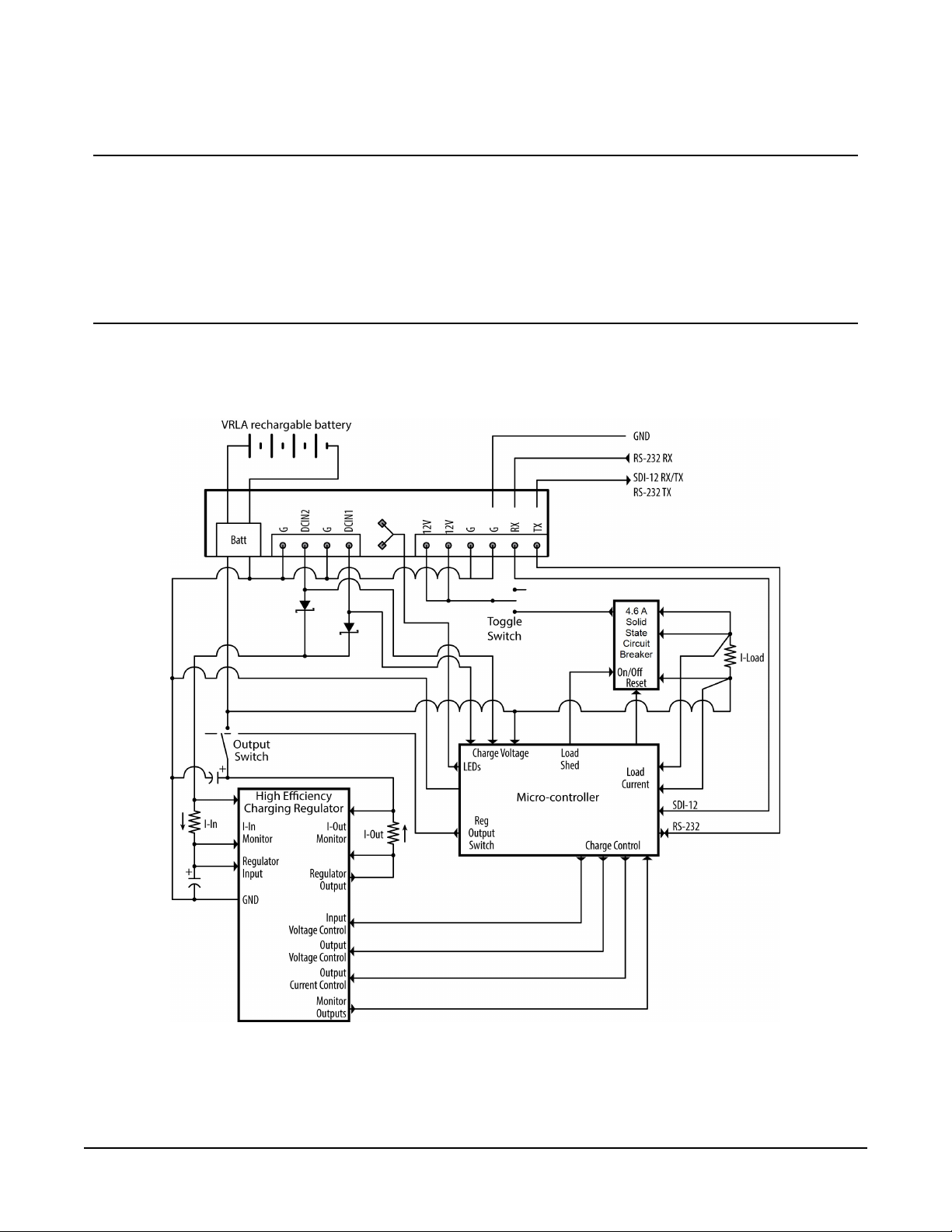
FIGURE 4-1 (p. 3) provides a simplified schematic of the CH201 charging regulator. See Table 5-1
(p. 7) for rechargeable batteries offered by Campbell Scientific.
FIGURE 4-1. CH201 schematic
CH201 12V Charging Regulator 3
Page 7

An unregulated solar panel or AC-to-DC converter typically supplies charging power to the
CH201. As shown in FIGURE 4-1 (p. 3), diodes connected to the two DCIn terminals provide input
reversal protection and isolation between power sources. DCIn terminals have a polarity that
must be followed. Connect the positive wires to the DCIn terminals, and connect the negative
wires to the G terminals. Reversed polarity inputs, however, will NOT damage the CH201. The
DCIn input terminals have an input current limit of approximately 10amps, making the CH201
well suited for 170watt or smaller solar panels. Higher powered solar panels may not damage the
CH201, but the additional power likely won't be fully used. Additionally, each input has a
programmable current limit. See (Optional) Configure using Device Configuration Utility (p. 12).
Internal diodes route power from the source with the highest input voltage. An AC-mainspowered application can use a solar panel for back-up if the AC-to-DC source has a higher
voltage than the solar panel. The solar power will be the primary supply and AC will be the
secondary supply if the solar panel has a higher output voltage than the AC-to-DC source.
The 12V output terminals are for powering a data logger and peripherals. A toggle switch
controls power to these output terminals. The total output current is limited by a 4.6A solid-state
circuit breaker.
Each battery family uses a unique charging algorithm to calculate the best charging voltage for
battery temperature. The algorithms use the charger temperature as the default temperature
source. If the charger and battery are in the same enclosure, the two temperatures will be similar.
If the battery will be in a separate enclosure, place a temperature sensor on or near the battery
and use the appropriate SDI-12 or RS-232 command to send this temperature to the module (see
Table 7-4 (p. 25) and Table 7-6 (p. 27)).
The CH201 has two LED indicators, the CHG (charge) LED and the CKBAT (check battery) LED.
Table 7-7 (p. 30) and Table 7-8 (p. 30) list the conditions and associated colors for the CHG and
CKBAT LEDs.
The CH201 communicates using a data logger or computer COM port. Data logger
communications can be done using SDI-12 or RS-232 as indicated in FIGURE 7-3 (p. 23) and
FIGURE 7-4 (p. 26). See Communications (p. 21) for details.
4.1 Communications interface
The CH201 can send data to the user to observe and manage power requirements and possible
problems. It can also be configured to work with a wide range of batteries and input power
supplies and test the existing battery system for possible shorting and sulfation problems.
The CH201 can be used without any configuration or communications. To take advantage of the
additional features of the CH201, however, the CH201 supports three kinds of communications:
CH201 12V Charging Regulator 4
Page 8
l Communications to a computer running Device Configuration Utility. This utility simplifies
configuration of the CH201 and allows for operating system updates. Device Configuration
Utility may be downloaded free of charge at www.campbellsci.com/downloads. See
(Optional) Configure using Device Configuration Utility (p. 12).
l SDI-12 communications as an SDI-12 sensor according to the SDI-12 standard
(www.SDI-12.org). See SDI-12 communications (p. 23) for an in depth explanation.
l RS-232 communications to a data logger or computer. See RS-232 communications (p. 25)
for an in-depth explanation.
SDI-12 data logger programming is usually simpler than RS-232 programming. Also, multiple
SDI-12 sensors can share a single data logger control or universal terminal if they have unique
SDI-12 addresses; RS-232 devices are limited to one device per terminal. The advantage of RS-232
is its speed can be faster than SDI-12.
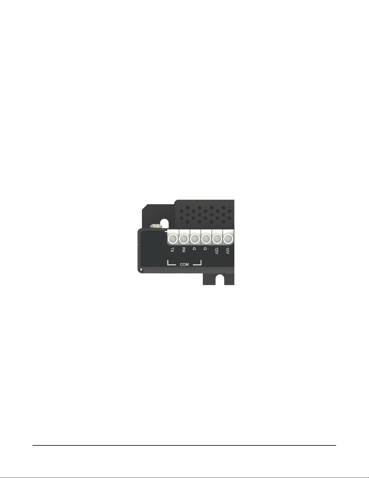
All CH201 serial communications use three COM terminals, TX, RX, and G. The CH201 will detect
the mode of communications and will reconfigure itself accordingly.
FIGURE 4-2. CH201 COM terminals
CH201 12V Charging Regulator 5
Page 9

5. Specifications
Operational Temperaturea:
Dimensions:
SOLAR Terminals (Solar Panel
or Other DC Source)
b
Input Voltage Range:
Maximum Charging Current:
Power Out (+12 terminals)
Voltage:
Battery Charging
c
CYCLE Charging:
FLOAT Charging:
Measurements
Input Voltage:
–40 to 60 °C
11.40 x 10.08 x 3.38 cm (4.49 x 3.97 x 1.33 in)
15 to 50VDC
10 A
Unregulated 12 V from battery
4.6 A solid state circuit breaker. Self-resettable thermal.
Vbatt(T) = 14.70 V – (24 mV) • (T – 25 °C)
Vbatt(T) = 13.65 V – (18 mV) • (T – 25 °C)
±(1% of reading +15 mV)
Battery Voltage:
Load Currentd:
Battery Currentd:
Charger Temperature:
±(2% of reading +15 mV)
±(2% of reading +2 mA)
±(2% of reading +10 mA)
± 2 °C
Quiescent Current
No Charge Source Present:
No Battery Connected:
Compliance:
300 μA maximum
Typical 5 mA at 40 VDC
View the EU Declaration of Conformity at
www.campbellsci.com/CH201
a
VRLA battery manufacturers state that “heat kills batteries” and recommend operating batteries at temperatures
below 50 °C.
b
Battery voltages below 8.7 V may result in <3.0 A current limit because of fold-back current limit.
c
Two-step temperature compensated constant-voltage charging for valve-regulated lead-acid batteries. Cycle and
float charging voltage parameters are programmable with the default values listed.
d
Impulse-type changes in current may have an average current measurement error of ±(10% of reading + 2 mA).
CH201 12V Charging Regulator 6
Page 10

Table 5-1: Available Campbell Scientific battery packs
Operating
Battery Pack Model
Amp-Hour Capacity
Temperature Range
1
Battery Family
(Ah)
(ºC)
Charge: –15 to 50
BP7 7
EnerSys/Genesis
Discharge: –20 to 60
Charge: –15 to 50
BP12 12
EnerSys/Genesis
Discharge: –20 to 60
Charge: –15 to 50
BP24 24
EnerSys/Genesis
Discharge: –20 to 60
BP84 84 –40 to 71 Concorde Sun Xtender
1
Battery specifications are from the manufacturer. The CH201 contains charging algorithms that optimize battery
charging over the range of –40 to 60 °C. Battery usage outside of manufacturer specifications could have unknown
effects on the life of the battery.
WARNING:
Battery life is shortened if the battery is allowed to discharge below 11.5 VDC. Low voltage
disconnect can be set in the CH201. Default low voltage disconnect is 6 VDC.
Charging requirements and tips:
Campbell Scientific offers a variety of solar panels and AC-to-DC transformers to meet the power
requirements of a system installation.
l 10 A is the highest input current that the CH201 can fully use. Although a solar panel or
transformer with a higher output current won't damage the CH201, its power will not be
fully used. Peak voltage of the solar panel must be less than 50VDC.
l Solar panel specifications assume a 1 kilowatt per square meter illumination and a solar
panel temperature of 25°C (77°F).
l Individual solar panels may vary up to 10%.
l Solar panel output voltage increases as the panel temperature decreases. VRLA batteries
also have increased output voltage as the battery temperature decreases.
l Higher latitudes and less sun hours during winter months might require a larger solar panel
than what is required to keep the battery charged during the summer.
l Use the Device Configuration Utility to change the current limit settings of DC In 1 or
DCIn2 to accommodate the current limit of a charging source. For example, set the
CH201 12V Charging Regulator 7
Page 11

current limit to 1.67 A to avoid tripping the power supply when using a wall charger with a
1.67 A current limit.
DCIn terminals have a polarity that must be followed. Connect the positive wires to the DCIn
terminals, and connect the negative wires to the G terminals. Reversed polarity inputs, however,
will NOT damage the CH201.
6. Installation
The CH201 module is designed to handle extreme conditions and to transmit charging, load, and
battery voltage and current information directly to a data logger by using SDI-12 or RS-232
commands. The data logger program can use the CH201 data to calculate a power budget for the
system and remotely pinpoint power problems. SDI-12 or RS-232 connections are not required for
normal operation, and the module is ready to use out of the box.
The CH201 has mounting holes on one-inch centers for mounting to a standard Campbell
Scientific enclosure backplate—see the enclosure manual for mounting suggestions. See FIGURE
6-1 (p. 9) for a typical enclosure installation using a CH201.
NOTE:
By default, the CH201 module is programmed with a battery capacity of zero amp-hours (Ah).
This sets the charger to charge at a lower current rate. A battery capacity must be configured
into the CH201 to enable the more aggressive two-step constant voltage charging scheme.
See Battery families and capacity (p. 15) for making changes by using Device Configuration
Utility. A downloadable example program using SDI-12 to set the battery capacity is available
at www.campbellsci.com/downloads/ch201-program-examples.
CH201 12V Charging Regulator 8
Page 12
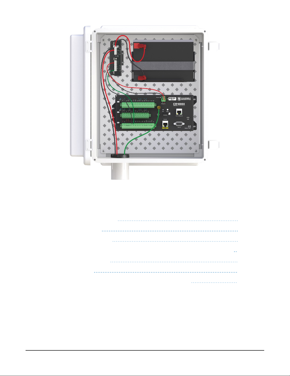
FIGURE 6-1. CH201 configured for SDI-12 communications
The installation section discusses the following:
6.1 Connect to power source 10
6.2 Connect to battery 11
6.3 Connect to data logger 11
6.4 (Optional) Connect to data logger for SDI-12 or RS-232 communications 11
6.5 Turn on power source 12
6.6 Turn on CH201 12
6.7 (Optional) Configure using Device Configuration Utility 12
CH201 12V Charging Regulator 9
Page 13

6.1 Connect to power source
DANGER:
Although the power supply and battery are low voltage, they can heat a metal ring,
watchband, or bracelet enough to burn skin or melt metal when shorted. Remove rings,
watches, or bracelets before hooking up power and connecting a battery.
Unlike the CH200, the CH201 has two DC inputs instead of one AC and one DC input. A solar
panel or AC-to-DC converter can connect to either input terminal. If both CH201 inputs are
connected to power sources, the power source with the highest voltage will supply power to the
CH201. Therefore, two solar panels can face different directions to allow the solar panel facing
the most direct sunlight to power the CH201.
Toggle the power supply switch to Off before connecting power to the CH201.
NOTE:
The switch on the CH201 only controls power going to the 12V terminals. The battery is
continuously charged regardless of the switch position when charging voltage is present.
6.1.1 Solar panel
WARNING:
To prevent sparking while wiring the solar panel, lay the solar panel face down on its packing
box or cover it with something to block the sunlight while wiring up the panel.
Connect the black (negative) wire from the solar panel to the G terminal that is adjacent to the
DCIn1 or DCIn2 terminal. Connect the red (positive) wire from an unregulated solar panel to
the DCIn1 or DCIn2 terminal. See FIGURE 6-2 (p. 10).
FIGURE 6-2. Voltage input connections on the CH201
CH201 12V Charging Regulator 10
Page 14

6.1.2 DC power
Double-check the input voltages coming in to the charger/regulator with a volt meter.
DC In 1 Input Voltage: 15 to 50VDC
DC In2 Input Voltage: 15 to 50VDC
WARNING:
Exceeding the maximum voltage will damage the CH201. Only one input is used at a time,
whichever has a higher voltage.
6.2 Connect to battery
Only use the following battery cables with the CH201: pn34029, pn34031, pn34040, and
pn36589. Connect the red wire to the positive battery post and the black wire to the negative
battery post. Inset the connector into the CH201 BAT port.
6.3 Connect to data logger
The CH201 comes with a 1-foot black wire attached to a G terminal block and a 1-foot red wire
attached to a 12V terminal block. The data logger includes a voltage input terminal connector.
The wires from the CH201 attach to this connector, which plugs into the PowerIn terminal on the
data logger. Attach the red wire from the CH201 to the 12V terminal on the connector; attach the
black wire to the G terminal, then plug the connector into the data logger.
6.4 (Optional) Connect to data logger for
SDI-12 or RS-232 communications
The TX, RX, and G terminals are used for communications. FIGURE 7-3 (p. 23) shows example
SDI-12 wiring and FIGURE 7-4 (p. 26) shows example RS-232 wiring.
NOTE:
Communications with the CH201 is required if the data logger is programmed to collect
information from the power supply. See Communications (p. 21) for more information.
CH201 12V Charging Regulator 11
Page 15

6.5 Turn on power source
Turn on the charging source power or uncover the solar panel. The green CHG LED should flash
every 4 to 5 seconds, which indicates correct incoming connections and adequate charging
voltage.
6.6 Turn on CH201
Toggle the switch on the CH201 supply to On. Check the voltage of the attached devices by using
a volt meter.
6.7 (Optional) Configure using Device
Configuration Utility
Using Campbell Scientific Device Configuration Utility is the easiest method to configure the
CH201 and the only method to update the operating system. If updating an operating system,
refer to Downloading an operating system (p. 31)
1. Select CH201 in the Device Type list on the left of the Device Configuration Utility window.
CH201 12V Charging Regulator 12
Page 16

2. Connect to the computer using an A200 device (see FIGURE 6-3 (p. 13)). Table 7-5 (p. 26)
and the bottom of the CH201 Device Configuration Utility screen show wiring to an A200.
FIGURE 6-3. Connecting the CH201 to a computer by using an A200
3. Select the appropriate Com Port.
4. Power the CH201 from the A200, battery, or DC power source on the DC In 1 or DC In 2
terminals.
CH201 12V Charging Regulator 13
Page 17

5. Click Connect to access the Settings Editor. The Settings Editor displays real-time values
(updated every second) and allows some settings to be changed.
6. To change a setting, select the field to be changed.
NOTE:
Although shown, the custom battery settings can only be changed if Custom is selected
for Battery Family.
7. Type a new value and press Enter. If the new value is not within an acceptable range, a red
message will appear to the right of the new value as shown in the following image.
Grayed-out fields cannot be changed. The bottom of the Settings Editor displays a
description of and information for the selected setting.
8. After changing settings, click Apply. If the CH201 accepts the settings, a configuration
summary will appear.
CH201 12V Charging Regulator 14
Page 18

9. Click Save to use the Read File option in the future to check settings or apply settings to
other CH201 regulators.
TIP:
Click the Factory Defaults button to revert to the factory default settings (read-only values are
not affected).
TIP:
Click the Read File button to restore settings based on a file that was created earlier.
6.7.1 Battery families and capacity
The CH201 has built-in charging algorithms for the EnerSys/Genesis NP series of batteries
(Campbell Scientific models BP7, BP12, and BP24), EnerSys/Cyclon Series, Concorde Sun Xtender
(BP84), or it can use custom algorithms entered by the user. The CH201 uses a second order
polynomial to make the correct battery charging adjustments for known battery families and
charging cycles. See FIGURE 6-4 (p. 16).
CH201 12V Charging Regulator 15
Page 19

FIGURE 6-4. Battery family list
Set the Battery Family to match the battery family being used. The default settings are Battery
Capacity of zero (0) and Battery Family of EnerSys/Genesis NP Series. Setting the Battery Capacity
to zero (0) forces the charger to only float charge the battery. Battery Capacity must be changed
to allow cycle charging. Table 6-1 (p. 17) shows the default settings for each battery family. The
settings are based on the following equation:
V
charge
(T) = C0+ C1(T-25°C) + C2(T-25°C)
2
Where:
T = Battery temperature in ° C.
C2= 0 for linear charge voltage vs. temperature relation.
CH201 12V Charging Regulator 16
Page 20

Table 6-1: Battery specifications
(V)
1
0
Float C
(mV/°C)
1
Float C
(mV/°C)
Minimum
2
2
Voltage (V)
Battery
family
Cycle C
1
(V)
0
Cycle C
(mV/°C)
1
Cycle C
(mV/°C)
2
2
Float C
EnerSys/
Genesis
NP Series 14.70 –24 0 13.65 –18 0 12.5
EnerSys/
Cyclon Family
Cyclon Series 14.70 –24 0.24 13.65 –24 0.24 13.2
Concorde
14.31 –24 0.24 13.29 –24 0.24 13.0
Sun Xtender
Custom
User
Settable
1
C0values are at 25 °C
User set
Default =
14.70
User set
Default =
–24
User set
Default =
0
User set
Default =
13.65
User set
Default =
–18
User set
Default =
0
User set
Default =
12.5
NOTE:
Consider changing the Custom Battery default settings. See your battery manufacturer
specifications for correct charging information.
The CH201 is designed to charge lead-acid batteries only. Lead-acid batteries come in three
styles. The first two styles are valve-regulated lead-acid (VRLA) batteries. VRLA batteries are
considered maintenance free because they do not require the addition of water to the cells. They
also vent less gas than flooded lead-acid batteries.
l Absorbed Glass Mat (AGM) maintenance-free battery. This style of battery has the
electrolyte (acid) absorbed and trapped in a glass fiber mat, which is sandwiched between
lead plates. This battery is sealed. No water or acid can be added and the design allows the
battery to be mounted in any position. This style battery is also called starved-electrolyte.
l Gel Cell maintenance-free battery. This battery has the electrolyte (acid) mixed with silica
dust to form an immobilized gel, which is sandwiched between lead plates. This battery is
sealed. No water or acid can be added. This type of battery can be sensitive to how it is
mounted. See manufacturer for details.
CH201 12V Charging Regulator 17
Page 21

l Flooded-Cell batteries. These are commonly used in automobiles. Deep-cycle marine
batteries are usually flooded-cell batteries. These batteries use a liquid electrolyte and
require the addition of water over time. They can only be mounted upright.
Different battery families and sometimes different manufacturers of the same battery style require
different charging algorithms. For example, Campbell Scientific sells VRLA AGM style batteries
from two different manufacturers — EnerSys/Genesis (BP7, BP12, and BP24) and Concorde
(BP84) — yet both batteries require a different charging algorithm. The charging algorithm
applied depends on the battery temperature and whether the battery is cycle charged (fast
charged) or float charged. Each manufacturer has a recommended charging algorithm for cycle
charging or float charging the battery. Cycle charging puts a higher voltage across the battery for
a short time, forcing the battery to take in more current and charge faster. Cycle charging is
recommended for systems running on solar panels so the maximum amount of current is moved
into the battery as quickly as possible. Battery amp-hour capacity must be known when cycle
charging to switch over to float charging at the correct point in the charging cycle, eliminating
overcharging and damaging the battery. Float charging puts a lower voltage across the battery
and is amp-hour independent.
FIGURE 6-5. Device Configuration Utility Advanced Settings tab
When using a charger with current limiting feature, use the Device Configuration Utility to
change the current limit in the CH201 to be slightly lower so that it doesn't trip the current limit
feature of the charge source (see FIGURE 6-5 (p. 18)).
CH201 12V Charging Regulator 18
Page 22

7. Operation
This section covers the following:
7.1 Charging algorithm 19
7.2 Maximum power point tracking 20
7.3 Communications 21
7.3.1 SDI-12 communications 23
7.3.2 RS-232 communications 25
7.4 LED indicators 29
7.1 Charging algorithm
The CH201 uses a two-step constant voltage charging algorithm, which is the preferred method
for rapidly charging VRLA batteries1from a solar panel. If the CH201 is powered solely from a
continuous power supply, bypass the two-step charging and use continuous, unaggressive
charging by using the battery capacity setting of zero (default value). When powered from a solar
panel, the battery charge deficit (Qloss) is compared to the specified battery capacity to
determine if aggressive cycle charging is necessary. Cycle charging is used if Qloss is determined
to be greater than 20% of the battery capacity. Upon detection that the battery is near full
charge, the constant voltage charging level is reduced from the aggressive cycle charging voltage
to the non-aggressive float-charge voltage to prevent overcharging and unwanted gassing of the
battery.
If the battery capacity is left at the default value of zero, Qloss always equals 0, which disables
cycle charging. Consequently, CH201 users must enter the battery capacity in the Device
Configuration Utility to enable the aggressive cycle charging capability of the two-step constant
voltage charging algorithm that is optimal for charging from solar panels.
Discharged VRLA batteries can initially accept large charging currents, often resulting in the
charger being unable to initially maintain a constant voltage because of current limiting by the
charge source or the charger itself. As a result, a typical two-step constant voltage charging cycle
usually consists of three distinct stages; a current limited charge stage, a constant cycle voltage
charge stage, and a constant float voltage charge stage (see FIGURE 7-1 (p. 20)). The current
limited stage and/or the constant cycle charge voltage stage may not occur if the battery size is
CH201 12V Charging Regulator 19
Page 23

small relative to the current capability of the charge source, or if the battery is near full charge at
the beginning of a charge cycle.
Normally, cycle charging terminates and float charging begins when Qloss has been reduced to
zero. An exception occurs if, during cycle charging the battery, charge current is reduced to
below C/100, where C is the user-entered battery capacity. This condition indicates the charger is
trying to aggressively cycle charge a fully charged battery, perhaps because a new fully charged
battery was swapped in to replace an old battery that suffered from a significant Qloss. During
cycle charging, if the battery charge current falls below C/100, cycle charging is terminated and
Qloss is zeroed.
FIGURE 7-1. Two-step constant voltage battery charging
7.2 Maximum power point tracking
FIGURE 7-2 (p. 21) shows the current and power versus voltage for a 70W solar panel. The graph
shows the maximum power point of operation for the solar panel. Adjusting the load on the solar
panel so it operates at this maximum power point is referred to as maximum power point
tracking (MPPT). MPPT is beneficial when insufficient power is available from the charge source,
which is the case during current limited charging. The noisy charging current and voltage
observed in FIGURE 7-1 (p. 20) during the initial current limited charging stage is due to the
MPPT algorithm of the CH201 searching for the maximum power point of the associated solar
panel.
CH201 12V Charging Regulator 20
Page 24

FIGURE 7-2. 70 W solar panel I – V and power characteristics
7.3 Communications
SDI-12 or RS-232 communications can be used to monitor the status of the battery, charging
source, and charging regulator. Table 7-1 (p. 22) lists the measurements available for both
communications modes.
CH201 12V Charging Regulator 21
Page 25

Table 7-1: CH201 measurements
Measurement Units
Battery voltage V
Battery current A
Load current A
DC In 1 voltage V
DC In 2 voltage V
Temperature °C
Charge state
Charge source
Check battery
SDI-12 Response
RS-232 Response/
DI-12 Meaning
–1 “REGULATOR FAULT”
0 “NO CHARGE”
1 “CURRENT LIMITED”
2 “CYCLE CHARGING”
3 “FLOAT CHARGING”
RS-232 Response/
SDI-12 Response
SDI-12 Meaning
0 “NONE”
1 "DC In 1"
2 “DC In 2”
0 = normal
1 = check battery (battery voltage less
than 10.5 V or battery is open circuit)
Target battery voltage V
Input voltage at maximum power V
Battery capacity Ah
Qloss Ah
The information from the regulator can also be used to calculate power usage by the battery and
the system. Measuring and storing power usage is useful to determine system power
requirements (power budget) and to help identify devices using too much power. A
CH201 12V Charging Regulator 22
Page 26

downloadable example program that monitors power usage is available at
www.campbellsci.com/downloads/ch201-program-examples.
7.3.1 SDI-12 communications
SDI-12 is a serial communications standard specifically designed for reading measurements from
multiple measurement sensors to data recorders, including Campbell Scientific data loggers.
Additional information about the SDI-12 protocol is available at www.SDI-12.org website and the
SDI-12 Sensors | Transparent Mode and SDI-12 Sensors | Watch or Sniffer Mode videos.
To communicate with the CH201 using SDI-12, connect the CH201 to the data logger as shown in
Table 7-2 (p. 23).
Table 7-2: Wiring for SDI-12 communications
CH201 connection CH201 terminal function Data logger connection
TX SDI-12 transmit and receive
G Ground ⏚ (analog ground)
1
U and C terminals are automatically configured by the measurement instruction.
C or U1configured for SDI-12
FIGURE 7-3. CH201 connected to a CR1000X via SDI-12
CH201 12V Charging Regulator 23
Page 27

If multiple SDI-12 devices are connected to a data logger, Campbell Scientific recommends using
separate terminals when possible. However, multiple SDI-12 devices can connect to the same
data logger control or U terminal. Each must have a unique SDI-12 address. Valid addresses are 0
through 9, a through z, and A through Z. The CH201 has a default SDI-12 address of 0. The SDI-12
address can be changed by using Device Configuration Utility or an SDI-12 command (aAb!).
For the CR6 and CR1000X data loggers, triggering conflicts may occur when a companion
terminal is used for a triggering instruction such as TimerInput(), PulseCount(), or
WaitDigTrig(). For example, if the CH201 is connected to C3 on a CR1000X, C4 cannot be
used in the TimerInput(), PulseCount(), or WaitDigTrig() instructions.
7.3.1.1 SDI-12 commands
Table 7-3: SDI-12 commands and responses
SDI-12 command
aM!, aMC!
aM1!, aMC1!
aM2!, aMC2!
1
a is the sensor address.
1
Values returned
1. Battery voltage
2. Battery current
3. Load current
4. DC In 1 voltage
5. DC In 2 voltage
6. Temperature
7. Charge state
8. Charge source
9. Check battery
1. Charge state
2. charge source
3. check battery
1. Target battery voltage
2. Input voltage at maximum
3. Battery capacity, Qloss
CH201 12V Charging Regulator 24
Page 28

Table 7-4: SDI-12 extended commands and responses
SDI-12 Command Description Response
Overrides the internal temperature
aXTnn.nn!
Where:
a = CH201 SDI-12 address
nn.nn = temperature in °C
aXTR!
Where:
a = CH201 SDI-12 address
measurement for 15 minutes (or until
canceled by a temperature restore
command). Useful for entering the
temperature of a remote battery.
Temperature range is –40.00 to
100.00°C.
Restore temperature measurement to
internal CH201 measurement.
aOK
aOK
aXCnn.n!
Where:
a = CH201 SDI-12 address
nn.n = battery capacity in Ah
aXRQ!
Where:
a = CH201 SDI-12 address
Downloadable example programs using these extended commands are available at
www.campbellsci.com/downloads/ch201-program-examples.
Enter battery capacity in Ah. Used to
charge the battery correctly. Must be
aOK
non-zero to use the quicker dual-rate
charging scheme.
Sets Qloss to zero. If not used, the
CH201 will automatically set Qloss to
aOK
zero after trying to cycle charge a
battery for eight hours or more.
7.3.1.2 CRBasic programming
The CRBasic instruction SDI12Recorder() is used to program a data logger to communicate
with the CH201 using SDI-12. Refer to the CRBasic help for information about this instruction.
Downloadable SDI-12 example programs are available at
www.campbellsci.com/downloads/ch201-program-examples.
7.3.2 RS-232 communications
The CH201 can use RS-232 to communicate directly with a Campbell Scientific data logger, or it
can communicate with a computer through an A200 module. The following table shows the
wiring for both connections.
CH201 12V Charging Regulator 25
Page 29

Table 7-5: Wiring for RS-232 communications
CH201 connection
TX Transmit
RX Receive
COM G Ground G G
DC In 1 or DC In2 12 VDC No connection +12Vdc
CH201
Data logger connection A200 connection
terminal function
C (even) (RX terminal
RX
of a COM port pair)
C (odd) (TX terminal
TX
of a COM port pair)
FIGURE 7-4. CH201 connected to a CR1000X via RS-232
RS-232 settings are as follows:
Bits per second:
Data bits:
Parity: None
Stop bits: 1
Flow control:
9600
8
None
CH201 12V Charging Regulator 26
Page 30

7.3.2.1 RS-232 commands
An RS-232 host initiates communication by sending an ASCII command string CH201(n)x
terminated with <CR> (carriage return, 0x0D in hexadecimal format), where n = command
number and x = command value.
The CH201 response string begins with an asterisk (*), followed by the comma-delimited data
strings and a checksum <CRC>. The string is terminated with <CR><LF> (carriage return 0x13,
line feed 0x10). Responses are numerical values with decimal points except for Charge State and
Charge Source, which appear as ASCII strings.
Table 7-6: RS-232 commands and responses
RS-232 command and response Description
Command:
CH201(0)0<CR>
Response:
*,
nnnn,nnnn,…,<CRC><CR><LF>
Where
nnnn = comma-delimited values and
strings
Read CH201 status.
Values Returned:
Battery voltage, battery current, load current, DC In 1
voltage, DC In 2 voltage, temperature, target battery
voltage, maximum power input voltage setting, battery
capacity, Qloss, charge state, charge source, check
battery
Command:
CH201(1)nn.nn<CR>
Where
nn.nn = temperature in °C
Response:
*Battery Temperature =
nnnn,<CRC><CR><LF>
Where
nnnn = set temperature
Command:
CH201(2)0<CR>
Response:
*OK<CRC><CR><LF>
Overrides the internal temperature measurement for 15
minutes (or until canceled by a temperature restore
command). Useful for entering the temperature of a
remote battery. Temperature range is –40.00 to
100.00°C.
Restore temperature measurement to internal CH201
measurement.
CH201 12V Charging Regulator 27
Page 31

Table 7-6: RS-232 commands and responses
RS-232 command and response Description
Command:
CH201(3)nnn.nn<CR>
Where
nnn.nn = battery capacity in Ah
Response:
*Battery capacity =
nnn.nn<CRC><CR><LF>
Command:
CH201(4)nnn.nn<CR>
Where
nnn.nn = battery charge deficit in Ah
Response:
*Qloss = nnn.nn
<CRC><CR><LF>
RS-232 command and response example:
Transmit: CH201(0)0<CR>
Receive:
*,14.726,0.0514,0.0017,23.045,0.2922,25.03,14.699,18.45,7.00,2.99
126,CYCLE CHARGING,DC In 1,0,<CRC><CR><LF>
Enter battery capacity in Ah. Used to charge the battery
correctly. Must be non-zero to use the quicker dual-rate
charging scheme.
Sets Qloss to zero. If not used, the CH201 will
automatically set Qloss to zero after trying to cycle
charge a battery for eight hours or more.
These values indicate the following:
Battery Voltage (V) = 14.726
Battery Current (A) = 0.0514
Load Current (A) = 0.0017
DC In 1 Voltage (V) = 23.045
DC In 2 Voltage (V) = 0.2922
Temperature (°C) = 25.03
Target Battery Voltage (V) = 14.699
Maximum Power Input Voltage (V) = 18.45
Battery Capacity (Ah) = 7.00
Qloss (Ah) = 2.99126
CH201 12V Charging Regulator 28
Page 32

Charge State = CYCLE CHARGING
Charge Source = DC In 1
Check Battery = 0
7.3.2.2 CRBasic programming
Use the SerialOut() and SerialInRecord() CRBasic instructions to program a data
logger to communicate with the CH201 using RS-232. To separate the numerical values, use
SplitStr().
The data logger can decipher the two-character checksum by using the CRBasic instruction
CheckSum(). Set the ChkSumType parameter to 5. A correct checksum will produce a result
of zero. A non-zero result indicates a transmission error(s) occurred.
The normal communication mode is SDI-12. Therefore, when the host first sends RS-232
characters, the first character might be missed. Avoid this by initiating RS-232 communication
with two backspace characters <BS> (0x08) as shown in the following example subroutine:
'Subroutine sends two backspace characters to the CH201 to
'wake it up and switch over to RS-232 mode.
Sub WAKEUP
SerialOut (COMPRT,CHR(&H08),"",1,3)
SerialOut (COMPRT,CHR(&H08),"",1,3)
EndSub
Downloadable example programs are available at www.campbellsci.com/downloads/ch201-
program-examples.
7.4 LED indicators
The CH201 has two LED indicators, the CHG (charge) LED and the CKBAT (check battery) LED.
Table 7-7 (p. 30) and Table 7-8 (p. 30) list the conditions and associated colors for the CHG and
CKBAT LEDs.
CH201 12V Charging Regulator 29
Page 33

Table 7-7: CHG LED
Condition Color/state
No valid charge source Off
Valid charge source and charging battery Flashing green
Valid charge source but battery discharging Flashing orange
Regulator fault detected Flashing red
Waiting for new operating system
(Downloading an operating system (p. 31))
Transferring operating system Solid green
Table 7-8: CK BAT LED
Condition Color/state
Battery voltage > 11.5 V Off
10.5 V ≤ battery voltage ≤ 11.5 V Flashing orange
Battery fault detected OR battery voltage < 10.5 V Flashing red
Solid red
8. References
1 – Genesis Application Manual – Genesis NP and NPX Series US-NP-AM-002, June 2006.
CH201 12V Charging Regulator 30
Page 34

Appendix A. Downloading an operating system
Although rarely needed, the operating system is easily updated by using the Device
Configuration Utility and the RS-232 interface cable (sold separately).
1. Download the latest CH201 operating system from www.campbellsci.com/ch201 to your
computer. This download is an executable file that automatically installs itself into the
correct folders. Run the file on the computer that will be used to connect to the CH201.
2. Connect the CH201 to power then connect it to the computer.
3. Open Device Configuration Utility.
4. Select CH201 from the Device Type list on the left of the Device Configuration Utility
window.
5. Select the Send OS tab.
6. Click Start and the Select the operating system to send dialog window appears.
7. Navigate to the CH201_[version number].a43 operating system file and click Open.
8. The CHG LED changes from red to green, indicating the module is receiving a new
operating system. The process will take a few minutes.
CAUTION:
DO NOT disconnect from the CH201 during this process.
9. When the operating system has been successfully sent, the green LED turns off and Device
Configuration Utility will bring up a window showing the new operating system was
successfully sent.
CH201 12V Charging Regulator 31
Page 35

FIGURE A-1. Downloading a new operating system
CH201 12V Charging Regulator 32
Page 36

Limited warranty
Products manufactured by Campbell Scientific are warranted by Campbell Scientific to be free
from defects in materials and workmanship under normal use and service for twelve months from
the date of shipment unless otherwise specified on the corresponding product webpage. See
Product Details on the Ordering Information pages at www.campbellsci.com. Other
manufacturer's products, that are resold by Campbell Scientific, are warranted only to the limits
extended by the original manufacturer.
Refer to www.campbellsci.com/terms#warranty for more information.
CAMPBELL SCIENTIFIC EXPRESSLY DISCLAIMS AND EXCLUDES ANY IMPLIED WARRANTIES OF
MERCHANTABILITY OR FITNESS FOR A PARTICULAR PURPOSE. Campbell Scientific hereby
disclaims, to the fullest extent allowed by applicable law, any and all warranties and conditions
with respect to the Products, whether express, implied or statutory, other than those expressly
provided herein.
Page 37

Assistance
Products may not be returned without prior authorization.
Products shipped to Campbell Scientific require a Returned Materials Authorization (RMA) or
Repair Reference number and must be clean and uncontaminated by harmful substances, such as
hazardous materials, chemicals, insects, and pests. Please complete the required forms prior to
shipping equipment.
Campbell Scientific regional offices handle repairs for customers within their territories. Please
see the back page for the Global Sales and Support Network or visit
www.campbellsci.com/contact to determine which Campbell Scientific office serves your country.
To obtain a Returned Materials Authorization or Repair Reference number, contact your
CAMPBELL SCIENTIFIC regional office. Please write the issued number clearly on the outside of
the shipping container and ship as directed.
For all returns, the customer must provide a “Statement of Product Cleanliness and
Decontamination” or “Declaration of Hazardous Material and Decontamination” form and
comply with the requirements specified in it. The form is available from your CAMPBELL
SCIENTIFIC regional office. Campbell Scientific is unable to process any returns until we receive
this statement. If the statement is not received within three days of product receipt or is
incomplete, the product will be returned to the customer at the customer’s expense. Campbell
Scientific reserves the right to refuse service on products that were exposed to contaminants that
may cause health or safety concerns for our employees.
Page 38

Safety
DANGER — MANY HAZARDS ARE ASSOCIATED WITH INSTALLING, USING, MAINTAINING, AND WORKING ON OR AROUND TRIPODS,
TOWERS, AND ANY ATTACHMENTS TO TRIPODS AND TOWERS SUCH AS SENSORS, CROSSARMS, ENCLOSURES, ANTENNAS, ETC. FAILURE
TO PROPERLY AND COMPLETELY ASSEMBLE, INSTALL, OPERATE, USE, AND MAINTAIN TRIPODS, TOWERS, AND ATTACHMENTS, AND
FAILURE TO HEED WARNINGS, INCREASES THE RISK OF DEATH, ACCIDENT, SERIOUS INJURY, PROPERTY DAMAGE, AND PRODUCT FAILURE.
TAKE ALL REASONABLE PRECAUTIONS TO AVOID THESE HAZARDS. CHECK WITH YOUR ORGANIZATION'S SAFETY COORDINATOR (OR
POLICY) FOR PROCEDURES AND REQUIRED PROTECTIVE EQUIPMENT PRIOR TO PERFORMING ANY WORK.
Use tripods, towers, and attachments to tripods and towers only for purposes for which they are designed. Do not exceed design limits. Be
familiar and comply with all instructions provided in product manuals. Manuals are available at www.campbellsci.com. You are responsible
for conformance with governing codes and regulations, including safety regulations, and the integrity and location of structures or land to
which towers, tripods, and any attachments are attached. Installation sites should be evaluated and approved by a qualified engineer. If
questions or concerns arise regarding installation, use, or maintenance of tripods, towers, attachments, or electrical connections, consult
with a licensed and qualified engineer or electrician.
General
l Protect from over-voltage.
l Protect electrical equipment from water.
l Protect from electrostatic discharge (ESD).
l Protect from lightning.
l Prior to performing site or installation work, obtain required approvals and permits. Comply with all governing structure-height
regulations.
l Use only qualified personnel for installation, use, and maintenance of tripods and towers, and any attachments to tripods and
towers. The use of licensed and qualified contractors is highly recommended.
l Read all applicable instructions carefully and understand procedures thoroughly before beginning work.
l Wear a hardhat and eye protection, and take other appropriate safety precautions while working on or around tripods and towers.
l Do not climb tripods or towers at any time, and prohibit climbing by other persons. Take reasonable precautions to secure tripod
and tower sites from trespassers.
l Use only manufacturer recommended parts, materials, and tools.
Utility and Electrical
l You can be killed or sustain serious bodily injury if the tripod, tower, or attachments you are installing, constructing, using, or
maintaining, or a tool, stake, or anchor, come in contact with overhead or underground utility lines.
l Maintain a distance of at least one-and-one-half times structure height, 6 meters (20 feet), or the distance required by applicable
law, whichever is greater, between overhead utility lines and the structure (tripod, tower, attachments, or tools).
l Prior to performing site or installation work, inform all utility companies and have all underground utilities marked.
l Comply with all electrical codes. Electrical equipment and related grounding devices should be installed by a licensed and qualified
electrician.
l Only use power sources approved for use in the country of installation to power Campbell Scientific devices.
Elevated Work and Weather
l Exercise extreme caution when performing elevated work.
l Use appropriate equipment and safety practices.
l During installation and maintenance, keep tower and tripod sites clear of un-trained or non-essential personnel. Take precautions to
prevent elevated tools and objects from dropping.
l Do not perform any work in inclement weather, including wind, rain, snow, lightning, etc.
Maintenance
l Periodically (at least yearly) check for wear and damage, including corrosion, stress cracks, frayed cables, loose cable clamps, cable
tightness, etc. and take necessary corrective actions.
l Periodically (at least yearly) check electrical ground connections.
Internal Battery
l Be aware of fire, explosion, and severe-burn hazards.
l Misuse or improper installation of the internal lithium battery can cause severe injury.
l Do not recharge, disassemble, heat above 100 °C (212 °F), solder directly to the cell, incinerate, or expose contents to water. Dispose
of spent batteries properly.
WHILE EVERY ATTEMPT IS MADE TO EMBODY THE HIGHEST DEGREE OF SAFETY IN ALL CAMPBELL SCIENTIFIC PRODUCTS, THE CUSTOMER
ASSUMES ALL RISK FROM ANY INJURY RESULTING FROM IMPROPER INSTALLATION, USE, OR MAINTENANCE OF TRIPODS, TOWERS, OR
ATTACHMENTS TO TRIPODS AND TOWERS SUCH AS SENSORS, CROSSARMS, ENCLOSURES, ANTENNAS, ETC.
Page 39

Campbell Scientific regional offices
Australia
Location:
Phone:
Email:
Website:
Brazil
Location:
Phone:
Email:
Website:
Canada
Location:
Phone:
Email:
Website:
China
Location:
Phone:
Email:
Website:
Garbutt, QLD Australia
61.7.4401.7700
info@campbellsci.com.au
www.campbellsci.com.au
São Paulo, SP Brazil
11.3732.3399
vendas@campbellsci.com.br
www.campbellsci.com.br
Edmonton, AB Canada
780.454.2505
data loggers@campbellsci.ca
www.campbellsci.ca
Beijing, P. R. China
86.10.6561.0080
info@campbellsci.com.cn
www.campbellsci.com.cn
France
Location:
Phone:
Email:
Website:
Vincennes, France
0033.0.1.56.45.15.20
info@campbellsci.fr
www.campbellsci.fr
Germany
Location:
Phone:
Email:
Website:
Bremen, Germany
49.0.421.460974.0
info@campbellsci.de
www.campbellsci.de
India
Location:
Phone:
Email:
Website:
New Delhi, DL India
91.11.46500481.482
info@campbellsci.in
www.campbellsci.in
South Africa
Location:
Phone:
Email:
Website:
Stellenbosch, South Africa
27.21.8809960
sales@campbellsci.co.za
www.campbellsci.co.za
Thailand
Location:
Phone:
Email:
Website:
UK
Location:
Phone:
Email:
Website:
USA
Location:
Phone:
Email:
Website:
Bangkok, Thailand
66.2.719.3399
info@campbellsci.asia
www.campbellsci.asia
Shepshed, Loughborough, UK
44.0.1509.601141
sales@campbellsci.co.uk
www.campbellsci.co.uk
Logan, UT USA
435.227.9120
info@campbellsci.com
www.campbellsci.com
Costa Rica
Location:
Phone:
Email:
Website:
San Pedro, Costa Rica
506.2280.1564
info@campbellsci.cc
www.campbellsci.cc
Spain
Location:
Phone:
Email:
Website:
Barcelona, Spain
34.93.2323938
info@campbellsci.es
www.campbellsci.es
 Loading...