

Page 1
Revision: 05/2020
Copyright © 2018 – 2020
Campbell Scientific, Inc.
Page 2

Table of contents
1. Cellular communications 1
2. Pre-installation 2
2.1 Establish cellular service 2
2.1.1 Campbell Scientific cellular data service 2
2.1.2 Other service providers 2
2.2 Install the SIM card 3
2.3 Konect PakBus Router setup 4
2.3.1 Get started 4
2.3.2 Set up Konect PakBus Router 5
3. Overview 7
4. QuickStart (integrated mode) 8
4.1 Modules using Konect PakBus Router (private dynamic IP) 10
4.1.1 Set up hardware 10
4.1.2 Configure data logger 10
4.1.3 Set up LoggerNet 13
4.1.4 Test the connection 15
4.2 Modules using a public static IP 16
4.2.1 Set up hardware 16
4.2.2 Configure data logger 16
4.2.3 Set up LoggerNet 18
4.2.4 Test the connection 20
5. Specifications 21
6. Installation 23
6.1 Base station requirements 23
6.2 Data logger site equipment 23
6.3 Wiring and connections 25
6.3.1 Module communications connections 26
6.3.2 Module power connections 28
6.3.3 Antenna connections 29
6.4 CELL200 series and data logger configuration 31
Table of contents - i
Page 3

6.4.1 Integrated mode option 31
6.4.2 Non-integrated mode option 31
6.4.2.1 Configure CELL200 series 32
6.4.2.2 Configure data logger 32
6.4.2.3 Set up hardware 32
6.4.2.4 Set up LoggerNet 33
6.4.2.5 Test the connection 35
6.4.3 Serial server mode option 36
6.4.3.1 Configure CELL200 series 36
6.4.3.2 Configure data logger 39
6.4.3.3 Set up hardware 39
6.4.3.4 Set up LoggerNet 39
6.4.3.5 Test the connection 41
6.4.4 Serial client mode option 42
6.4.4.1 Configure CELL200 series 43
6.4.4.2 Configure data logger (optional) 45
6.4.4.3 Set up hardware 46
6.4.4.4 Set up LoggerNet 46
6.4.4.5 Test the connection 47
6.4.5 Serial server/client mode option 48
6.4.5.1 Configure CELL200 series 49
6.4.5.2 Configure data logger 52
6.4.5.3 Set up hardware 53
6.4.5.4 Set up LoggerNet 53
6.4.5.5 Test the connection 54
7. Operation and maintenance 55
7.1 Ports 55
7.2 LED indicator lights 56
7.3 Signal strength 56
Appendix A. Controlling power to the CELL200 series 58
Appendix B. Configuring settings and retrieving status information with the
CRBasic program 60
B.1 Using the SetSetting() instruction 60
Appendix C. Cellular module terminal functionality 64
Table of contents - ii
Page 4

C.1 Using cell modem terminal functionality 65
C.2 Status commands 72
C.3 Set commands 77
C.4 Action commands 79
Appendix D. Updating the operating system and firmware 81
D.1 Using the web interface (cell.linktodevice.com) 81
D.2 Using Device Configuration Utility 83
Appendix E. Verizon Wireless and AT&T 85
E.1 Verizon Wireless 85
E.2 AT&T 86
Appendix F. Cellular module regulatory information 87
F.1 Important information for North American users 87
F.2 RF exposure 87
F.3 EU 88
Table of contents - iii
Page 5
1. Cellular communications
This manual provides information for interfacing CELL200 Series 4G LTE Cellular Modules to
Campbell Scientific data loggers.
Use of the CELL200 series requires a cellular line of service. The products compatible with
Verizon, AT&T, T-Mobile, Vodafone, and Telstra are shown in the following table.
Product
Cellular
protocol
4G LTE
CELL205
with
automatic
3G fallback
CELL210 4G LTE CAT-1
4G LTE
with
CELL215
automatic
3G and
2G fallback
4G LTE
with
CELL220
automatic
3G fallback
Market Verizon AT&T T-Mobile Vodafone Telstra Other
North
✔ ✔ ✔
America
United
✔
States
EMEA ✔ ✔
Australia
and New
✔ ✔
Zealand
1
CELL225 4G LTE Japan ✔
1
More than 600 other providers are available worldwide through Campbell Scientific. See Establish cellular service
(p. 2) for more information.
Before using the CELL200 series, please review:
l Safety
l Pre-installation (p. 2)
l QuickStart (integrated mode) (p. 8)
CELL200-Series 4G LTE Cellular Module 1
Page 6

2. Pre-installation
TIP:
Check www.campbellsci.com to ensure you are using the latest data logger support software
and data logger operating system (OS).
Updating the OS during system setup and testing, or onsite is recommended. Sending an OS
to a remote data logger will interrupt the data logger program. If you have questions, contact
Campbell Scientific for assistance (https://www.campbellsci.com/support).
2.1 Establish cellular service
For better security, we recommend using Konect PakBus® Router with a private dynamic IP
address. This method allows only incoming PakBus communication. No other incoming
communication is supported. However, all forms of outbound communication from the data
logger are supported, including but not limited to PakBus, email, and ftp.
A public static IP address can also be used. This provides more incoming communication
functionality, but is less secure and more vulnerable to unsolicited traffic.
NOTE:
A public static IP account must be used when the module is set up in serial server mode.
Private dynamic IP accounts do not support the serial server mode.
2.1.1 Campbell Scientific cellular data service
Campbell Scientific can provide subscriptions to cellular service through Verizon, AT&T,
T-Mobile, Vodafone, Telstra, and over 600 other providers worldwide. When this cellular service
is purchased with the module, the module will come pre-provisioned with the required SIM card
and APN. If you have already purchased the CELL200 series, call Campbell Scientific to set up
service.
2.1.2 Other service providers
While using Campbell Scientific is the simplest way to obtain cellular data service for your
module, you can go directly to a provider. For more information on obtaining service directly
from Verizon and AT&T, see Verizon Wireless and AT&T (p. 85).
CELL200-Series 4G LTE Cellular Module 2
Page 7

TIP:
Prepaid cellular data plans may experience service slow downs when data limits are reached.
If file transfer from a cellular-connected data logger works initially, but later has problems,
check for data overage on the cellular plan.
This does not apply to Campbell Scientific cellular data services.
2.2 Install the SIM card
NOTE:
If you purchased cellular service from Campbell Scientific with the module, it will come with
the SIM (Subscriber Identity Module) card already installed. Proceed to Konect PakBus Router
setup (p. 4)
The CELL200 series requires a Micro-SIM (3FF) (6 position / contacts); a smartcard that securely
stores the key identifying a mobile subscriber. You should only need to install the SIM once in
the life of the module.
To install the SIM card:
1. Remove the SIM card cover.
2. Note the location of the notched corner for correct alignment. The gold contact points of
the SIM face down when inserting the SIM card as shown in the following figure. Gently
slide the card into the slot until it stops and locks into place. To eject the SIM card, press it
in slightly and release.
3. Replace the SIM card cover.
CELL200-Series 4G LTE Cellular Module 3
Page 8

FIGURE 2-1. SIM card installation
2.3 Konect PakBus Router setup
For better security, we recommend using Konect PakBus® Router with a private dynamic IP
address. This method allows only incoming PakBus communication. No other incoming
communication is supported. However, all forms of outbound communication from the data
logger are supported, including but not limited to PakBus, email, and ftp. Complete the steps in
the following two sections.
2.3.1 Get started
You will need the Konect PakBus Router redemption code that came on a card with the CELL200
series.
CELL200-Series 4G LTE Cellular Module 4
Page 9
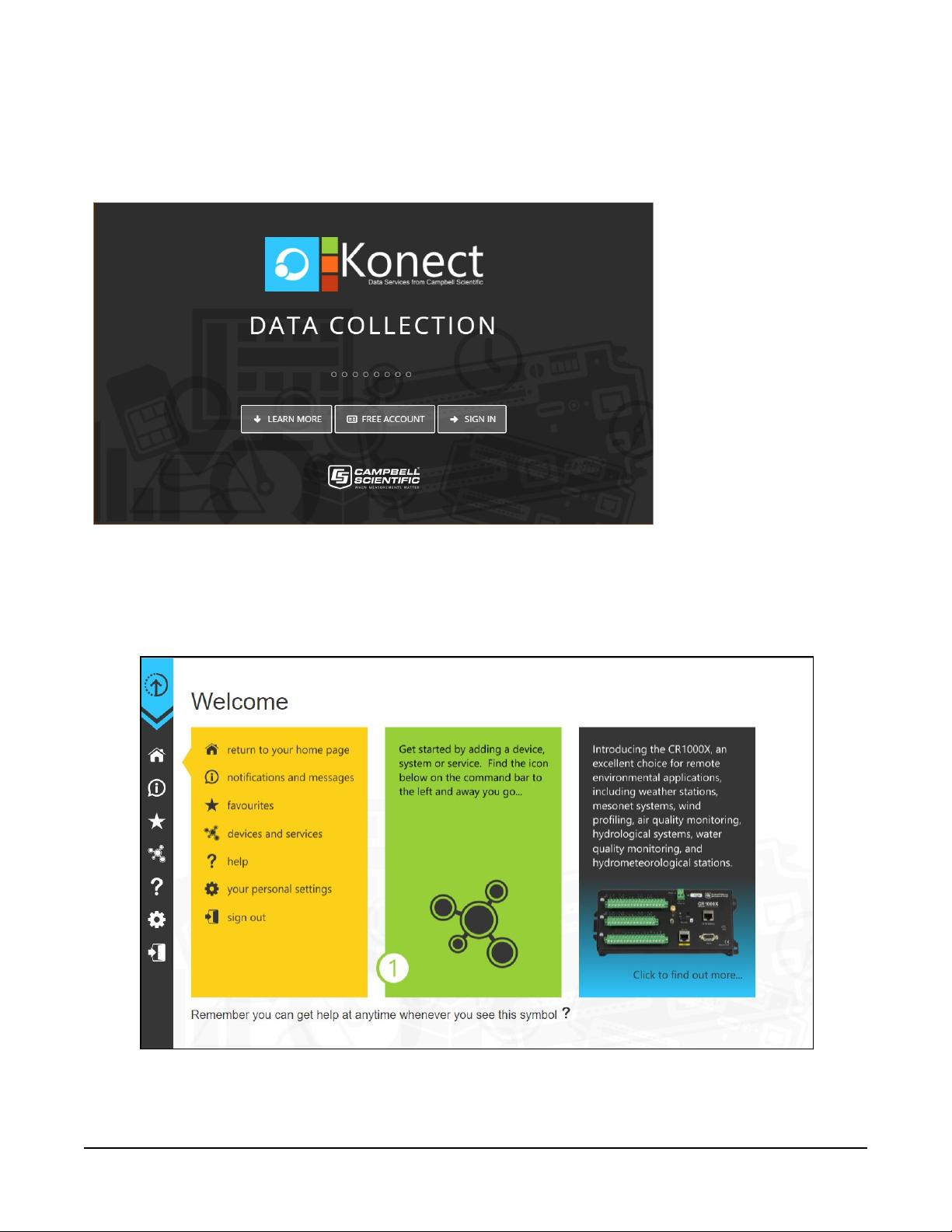
Open a web browser and go to www.konectgds.com.
First-time users need to create a free account. After you submit your information, you will receive
two emails up to five minutes apart. One email will contain a Passport ID and the other your
Password. If emails are not received, check your email junk folder.
2.3.2 Set up Konect PakBus Router
1. Sign in to www.konectgds.com using your Passport ID and Password found in the two
received emails. Once logged in, you will be at the Welcome page.
CELL200-Series 4G LTE Cellular Module 5
Page 10
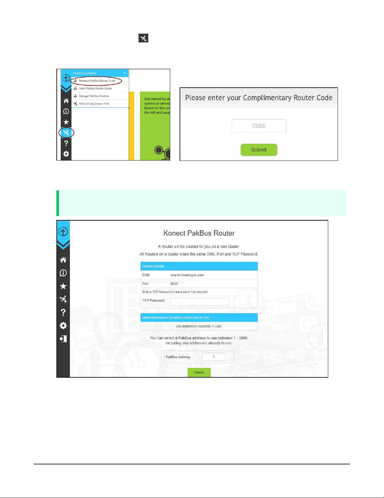
2.
Click devices and services on the command bar to the left and select Redeem PakBus
Router Code. Enter your complimentary Router Code found on the included card with your
cellular-enabled device and click Submit.
3. The next screen shows the assigned DNS address and Port for the router. Enter a TCP
Password and select a unique PakBus Address for your data logger.
TIP:
Make note of this information for use in later steps.
4. Click Submit.
CELL200-Series 4G LTE Cellular Module 6
Page 11
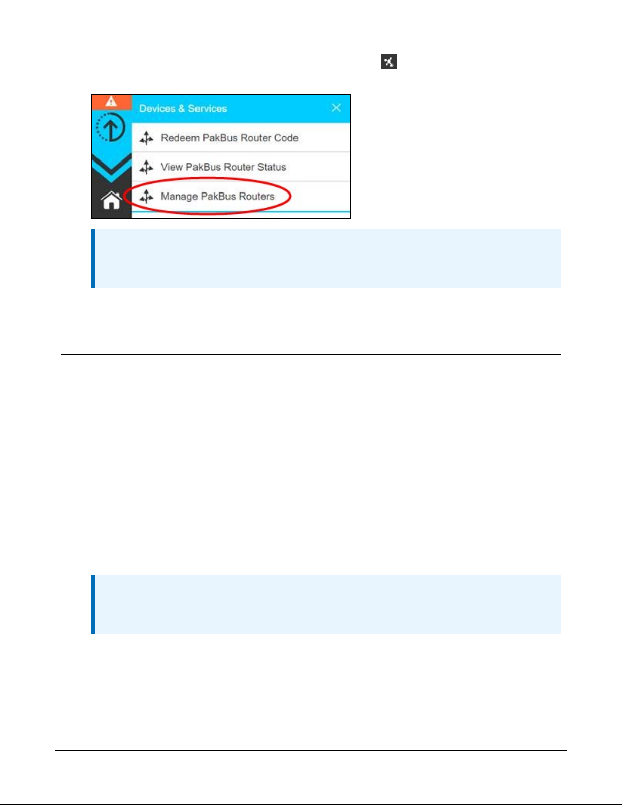
5.
To edit settings at a later date, click devices and services on the command bar and
select Manage PakBus Routers.
NOTE:
The DNS address and Port number, assigned when your account was setup, cannot be
edited.
3. Overview
The CELL200-series modules may be configured in one of five ways, depending on the data
logger, communications type, and needs of the user.
l Integrated: The module mimics the behavior of our integrated cell modems. No settings
are configured directly in the module. All settings are configured in the attached data
logger.
l Non-integrated: The module mimics the behavior of our older cellular modems. Settings
must be configured in both the module and the data logger.
l Serial Server: In this mode, the module receives IP communications over the cellular
network and converts those to serial communications to pass on to the data logger. From
the perspective of the data logger, this is no different than a serial cable connecting it to a
computer.
NOTE:
A public static IP account must be used when the module is set up in serial server
mode. Private dynamic IP accounts do not support the serial server mode.
CELL200-Series 4G LTE Cellular Module 7
Page 12
l Serial Client:Use this mode when the module is behind a cellular provider firewall and it
has a privatedynamic IP address. In serial client mode the module will connect to the
cellular network and initiate a TCP client socket connection.
l Serial Server/Client:In serial server/client mode the module connects to the cellular
network and opens a listening port. When a client connects to the listening port, the
CELL200 series will be in "Serial Server" mode, as described earlier. When no client is
connected to the listening port, the CELL200 series will be in "Serial Client" mode, as
described earlier, and all data on the active port will be sent and received through the
initiated TCP client socket connection.
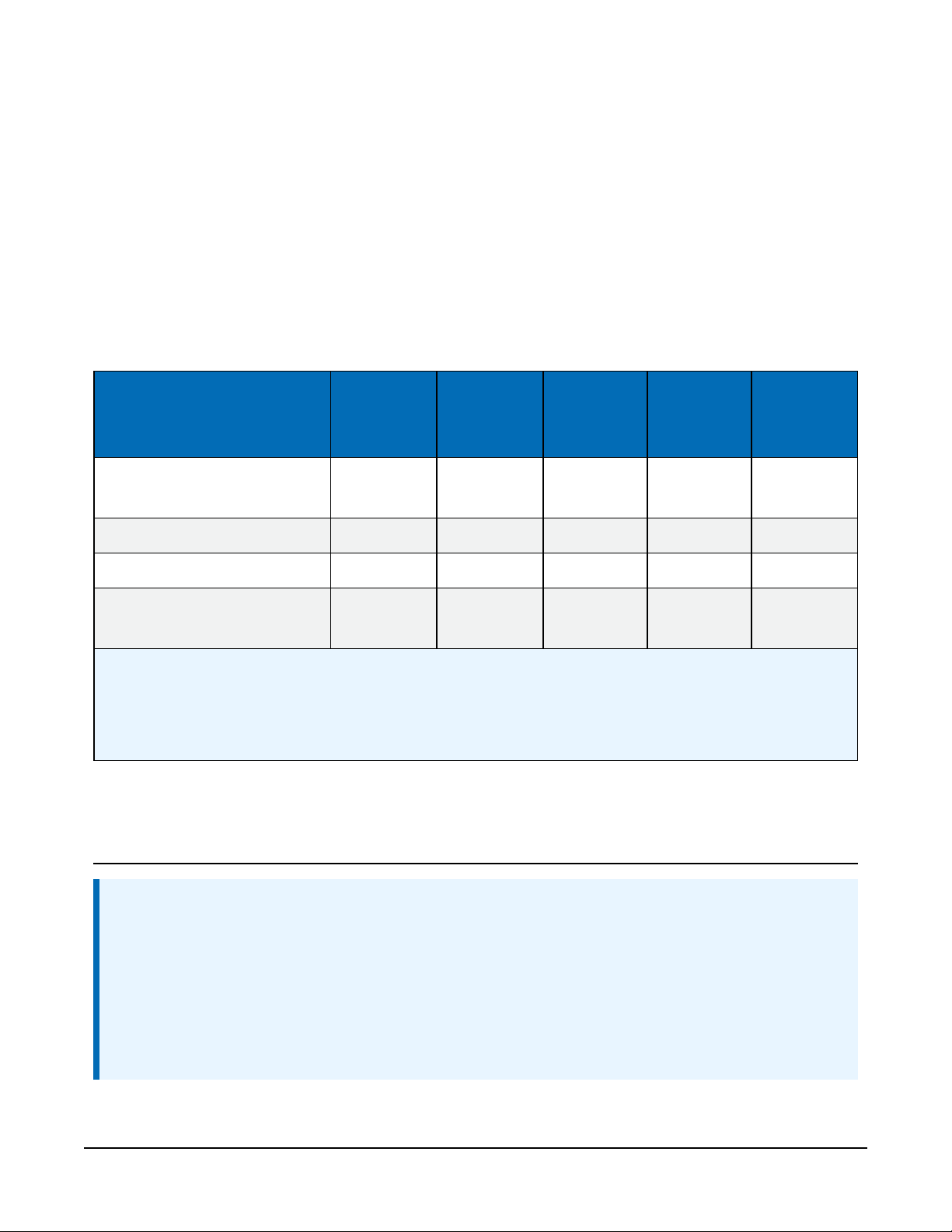
Data loggers compatible with each mode are shown in the following table.
Integrated
PPP
Non-
integrated
PPP
Serial
server
Serial
2
client
3
Serial
server/
client
CR6 series/CR1000X/
CR300series
1
✔ ✔ ✔ ✔ ✔
CR1000/CR3000/CR800series ✔ ✔ ✔ ✔
CR200(X) series ✔ ✔ ✔
Array-based
✔ ✔ ✔
(Edlog)dataloggers
1
Integrated PPP mode requires operating system 03.00 or later for the CR1000X, 09.00 or greater for the CR6
series, and 08.00 or later for the CR300 series.
2
Serial server mode requires a public static IP account.
3
Requires CELL200 series OS 2.00 or later.
3
4. QuickStart (integrated mode)
NOTE:
This QuickStart describes configuring the CELL200 series in integrated mode (mimicking our
internal cell modems) with its default settings. It can also be configured in non integrated or
serial server mode.
This QuickStart section does not apply to CR3000, CR1000 and CR800-series users. See
Overview (p. 7) for more information on the different modes. See CELL200 series and data
CELL200-Series 4G LTE Cellular Module 8
Page 13
logger configuration (p. 31) for more information on configuring the module in the different
modes.
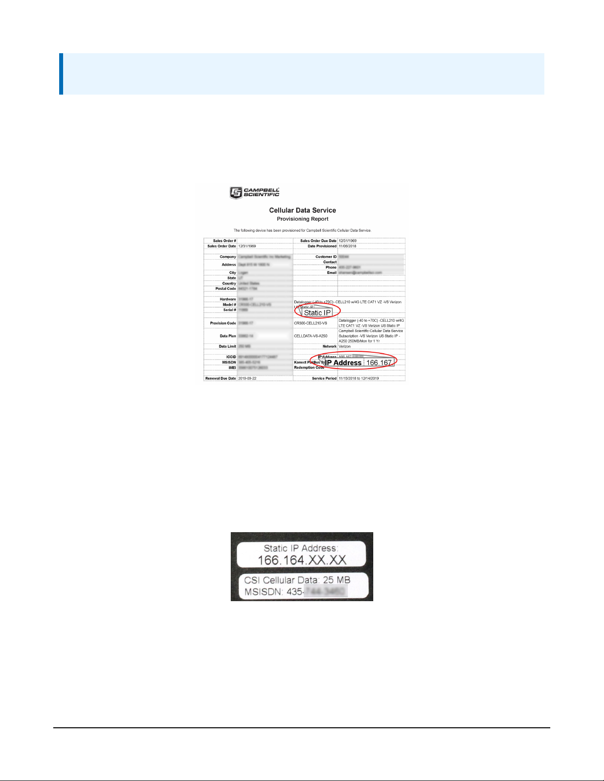
The Provisioning Report received with your Cellular Data Service shows whether the module was
configured with a private dynamic or public static IP address. See FIGURE 4-1 (p. 9) for an
example of a Campbell Scientific Provisioning Report. Other cellular providers should provide
similar information.
FIGURE 4-1. Static IP provisioning report
Additionally, Campbell Scientific cellular modules configured with a public static IP address will
have two stickers on the module, as shown in FIGURE 4-2 (p. 9). One sticker will show the
module phone number and data plan. The second sticker will show the static IP address.
Campbell Scientific cellular modules configured with a private dynamic IP address will have one
sticker on the module. It will show the module phone number and data plan.
FIGURE 4-2. Module with public static IP address
CELL200-Series 4G LTE Cellular Module 9
Page 14

4.1 Modules using Konect PakBus Router (private dynamic IP)
4.1.1 Set up hardware
1. Connect the Cellular antenna.
2. Connect your data logger to the CELL200-series module RS-232 or CS I/O port. See Wiring
and connections (p. 25).
3. If not connecting through CS I/O, provide power to the CELL200 series.
4.1.2 Configure data logger
1. Connect to your data logger by using Device Configuration Utility.
2. On the Network Services tab in the PakBus/TCP Client field, enter the DNS address and
Port number noted during the Konect PakBus Router setup.
3. On the PPP tab, set Config/Port Used to CS I/O SDC8 or RS-232, depending on how you
are connected to the data logger.
4. (Optional) On the PPP tab, set User Name and Password if required by your cellular carrier
(usually outside of the United Sates).
5. Verify the Modem Dial String setting is blank.
6. If connecting through RS-232, on the Comport Settings tab, set RS232 BaudRate to
115200Fixed.
7. Shut down Device Configuration Utility and start it again. This will activate the Cellular tab
needed for the next step.
CELL200-Series 4G LTE Cellular Module 10
Page 15
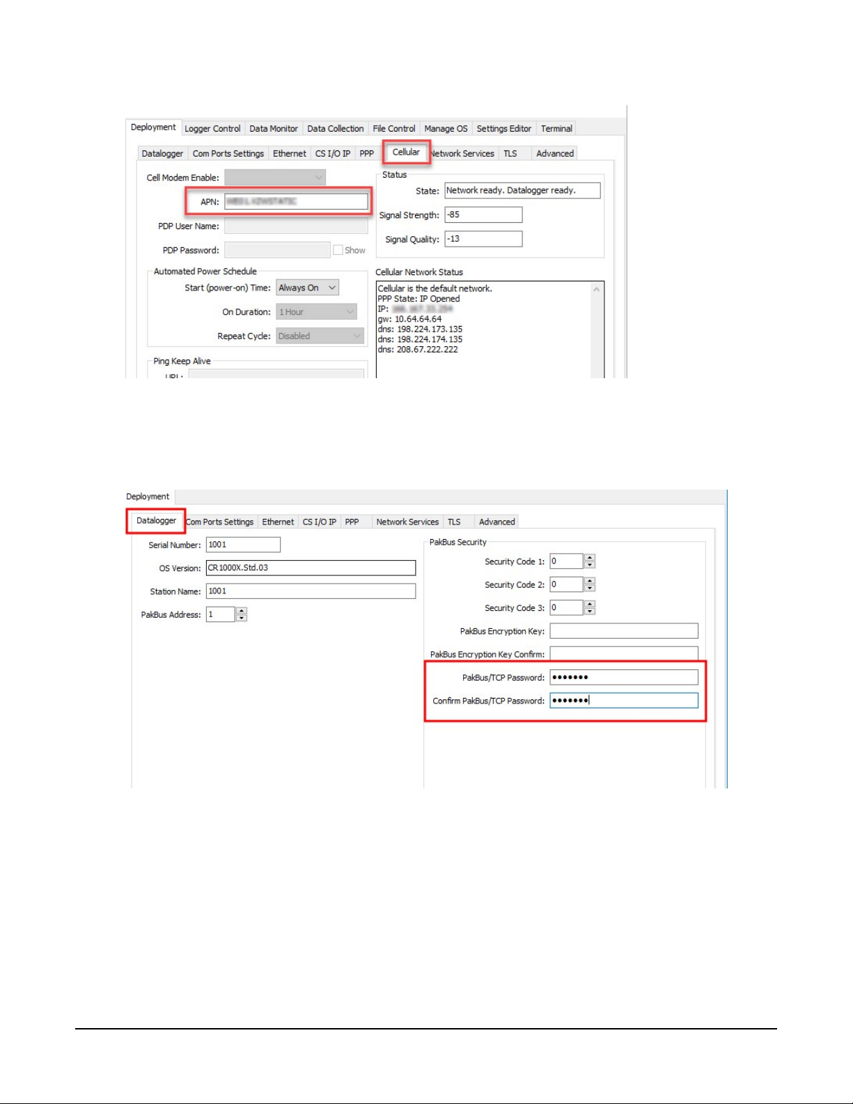
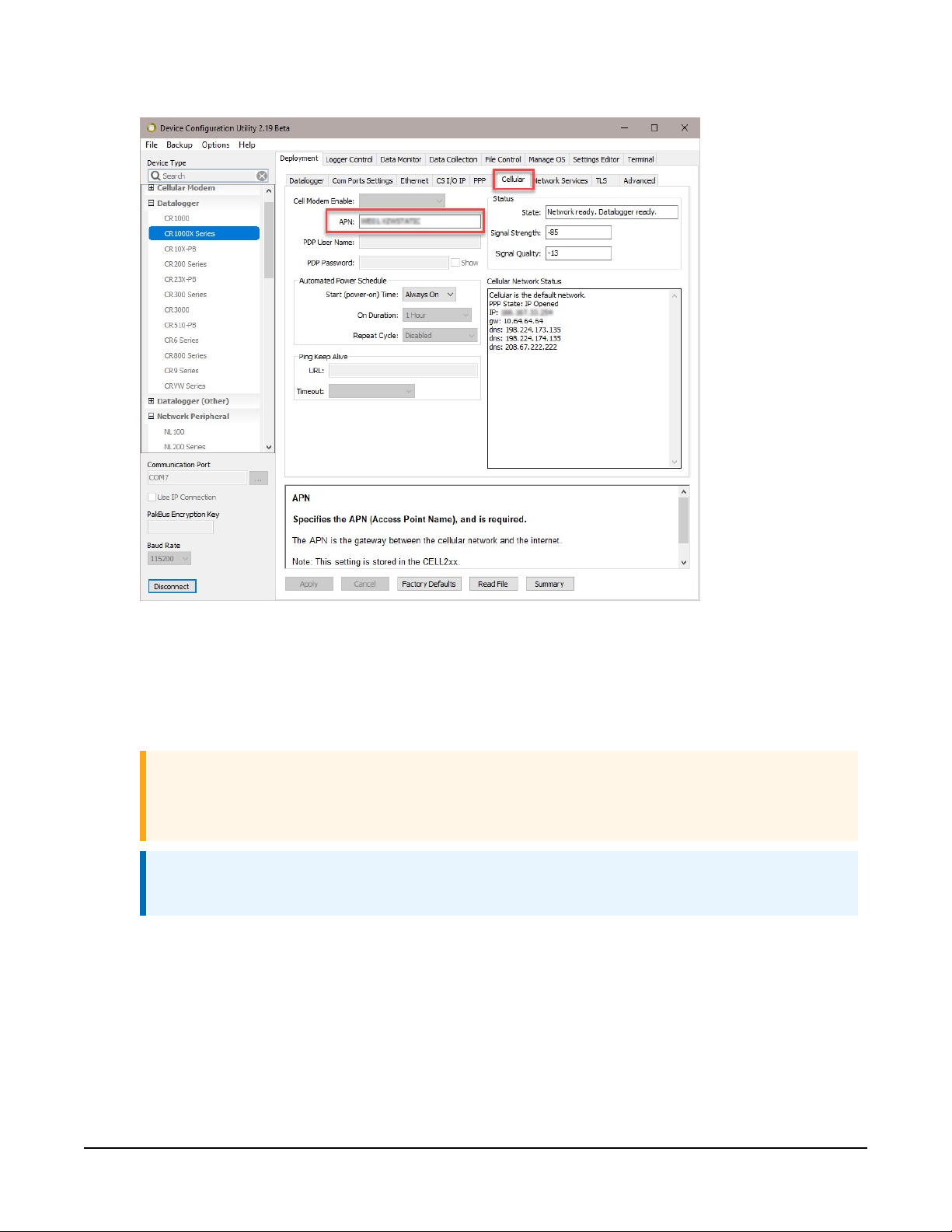
8. On the Cellular tab, enter the APN provided by your cellular provider.
9. On the Datalogger tab enter the PakBus/TCP Password twice. This setting specifies a
password that will make the data logger authenticate any incoming or outgoing
PakBus/TCP connection. It must match the value entered in the Konect PakBus Router
setup.
CELL200-Series 4G LTE Cellular Module 11
Page 16
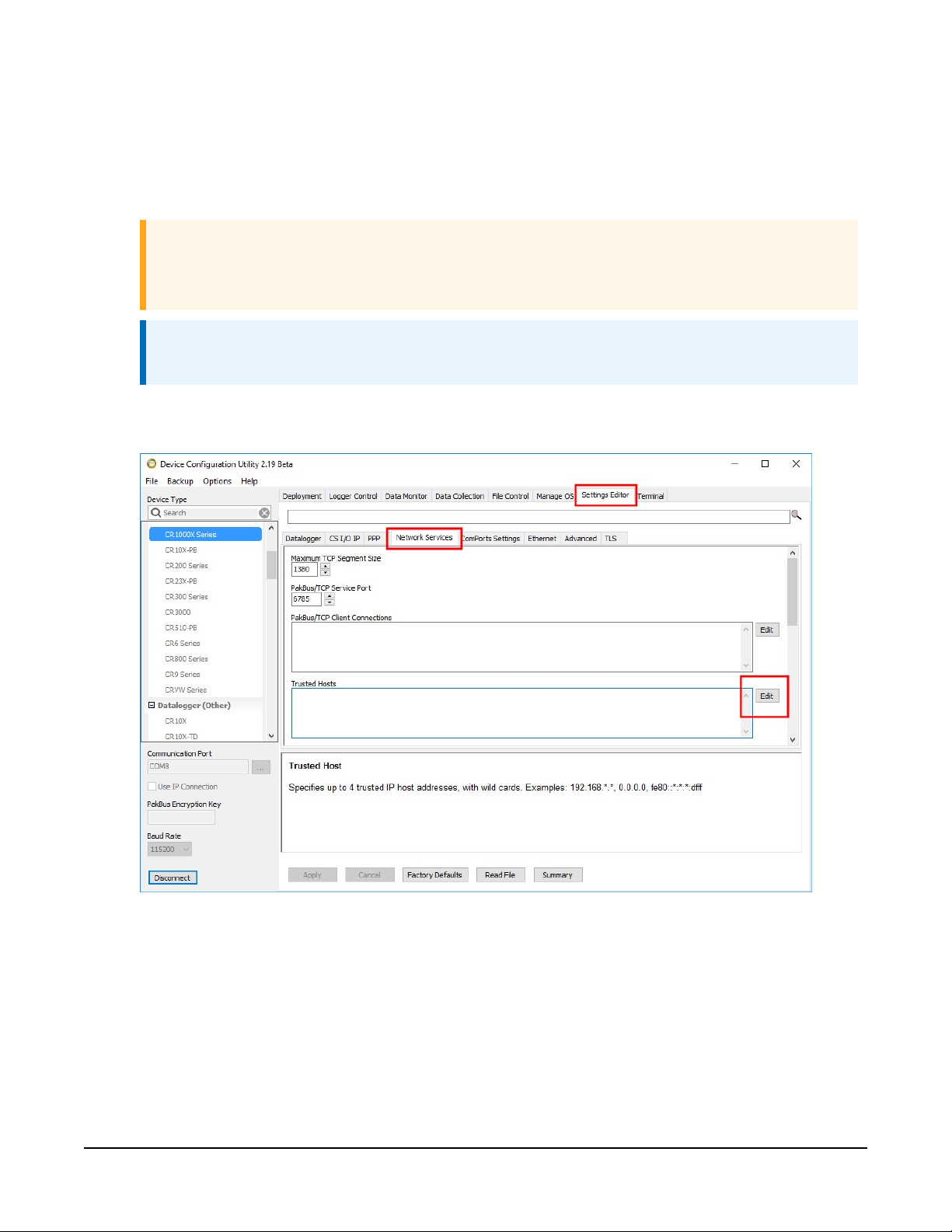
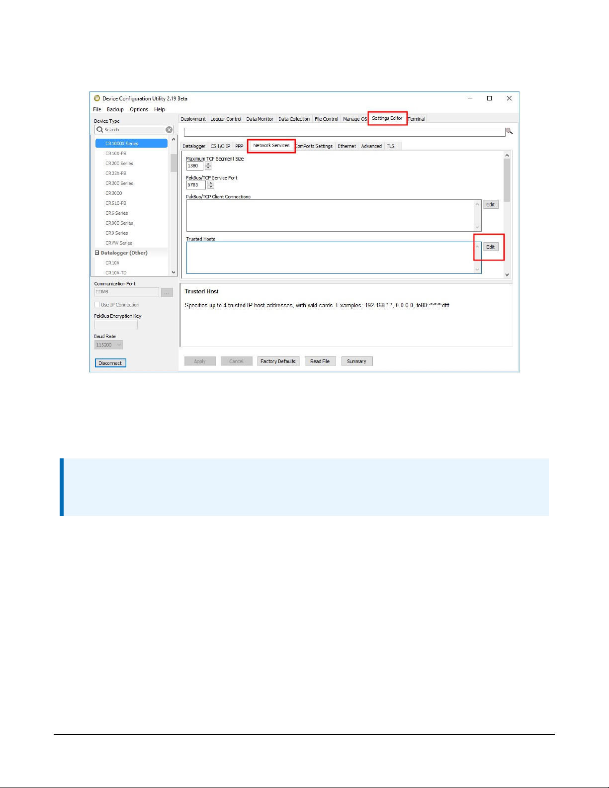
10. (Optional) By default, the CELL200 series will accept incoming communications from any IP
address. This can be a security risk. You may specify up to four IP addresses, with wild cards,
to limit connections to only those trusted sources. Use an asterisk (*) as a wild card. For
example, a setting of 166.22.*.* would allow connections from devices that have IP
addresses starting with 166.22. Both IPv4 and IPv6 addresses are supported.
CAUTION:
Only set a Trusted IP address if you are familiar with their use. Consult your IT
department or Campbell Scientific for assistance.
NOTE:
This setting does not affect outbound connections, only incoming connections.
In the Device Configuration Utility go to the Settings Editor then Network Services. Next to
the Trusted Hosts field, click Edit and Add your trusted IP addresses, one at a time.
11. Click Apply to save the changes.
CELL200-Series 4G LTE Cellular Module 12
Page 17
4.1.3 Set up LoggerNet
The LoggerNet Network Map is configured from the LoggerNet Setup screen.
NOTE:
Setup has two options, EZ (simplified) and Standard. Click on the View menu at the top of
the Setup screen, and select Standard view.
From the LoggerNet toolbar, click Main > Setup and configure the Network Map as described in
the following steps:
1. Select Add Root > IPPort.
2. Select PakBusPort and pbRouter for PakBus data loggers such as the CR1000X or CR300.
3. Add a data logger to the pbRouter.
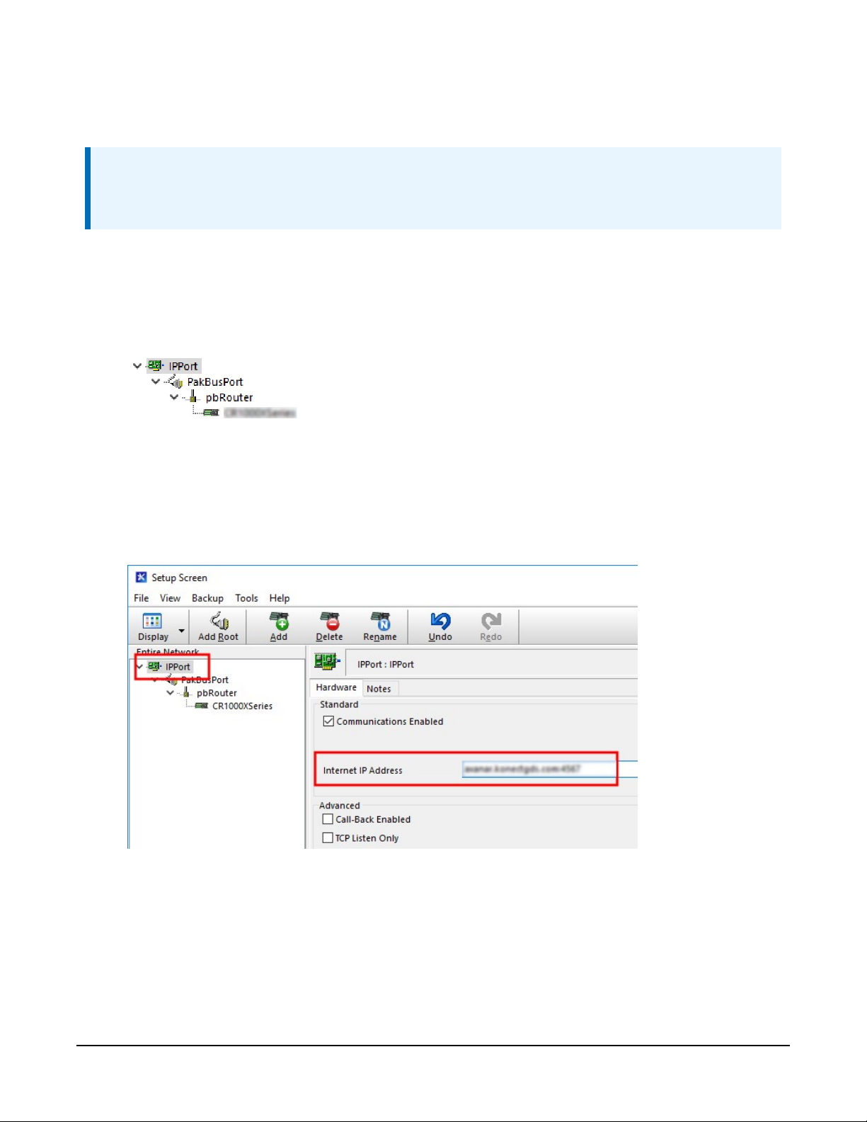
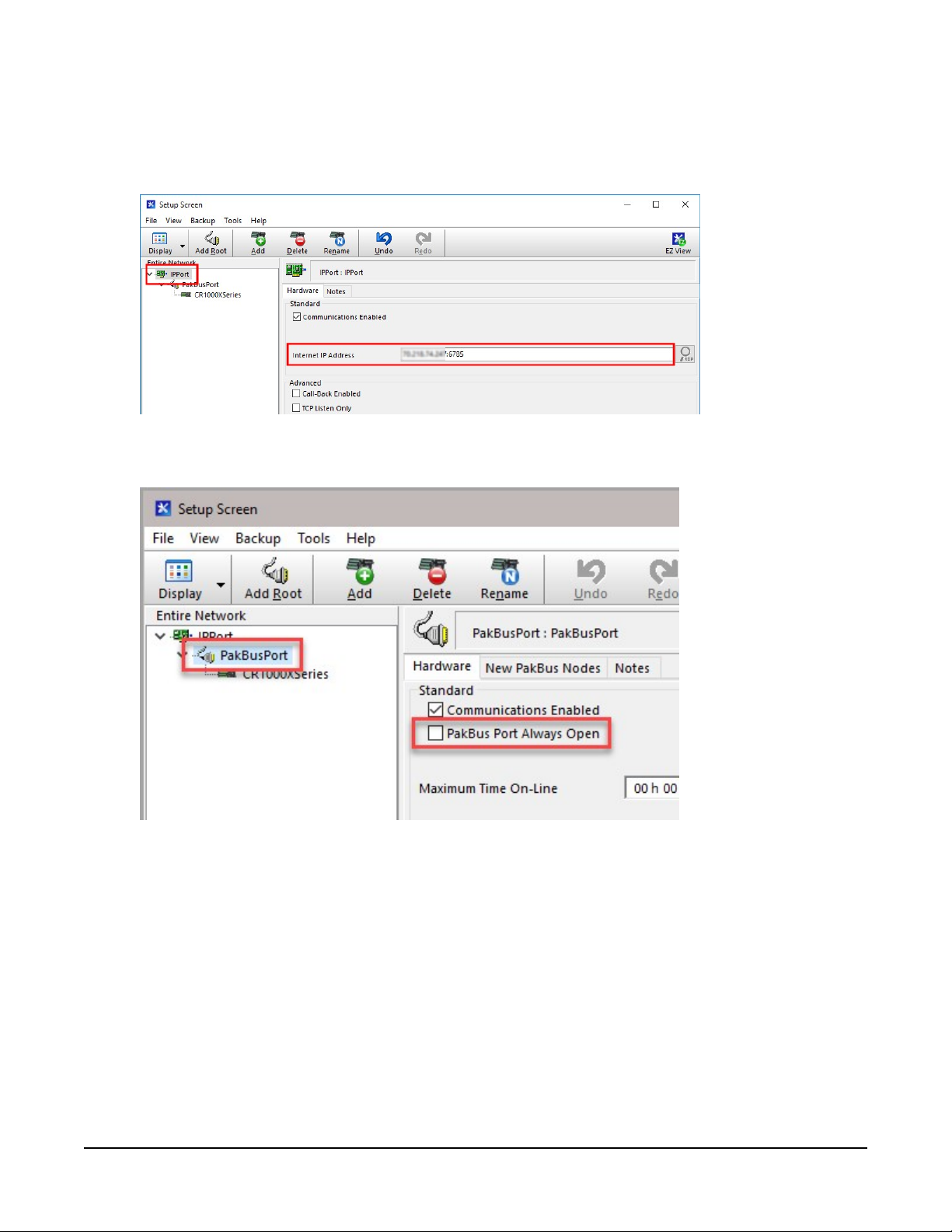
4. Select the IPPort in the Network Map. Enter the Konect PakBus Router DNS address and
port number as noted in the Konect PakBus Router setup. The DNS address and port
number are input in the Internet IP Address field separated by a colon. For example,
axanar.konectgds.com:pppp where pppp is the port number.
CELL200-Series 4G LTE Cellular Module 13
Page 18
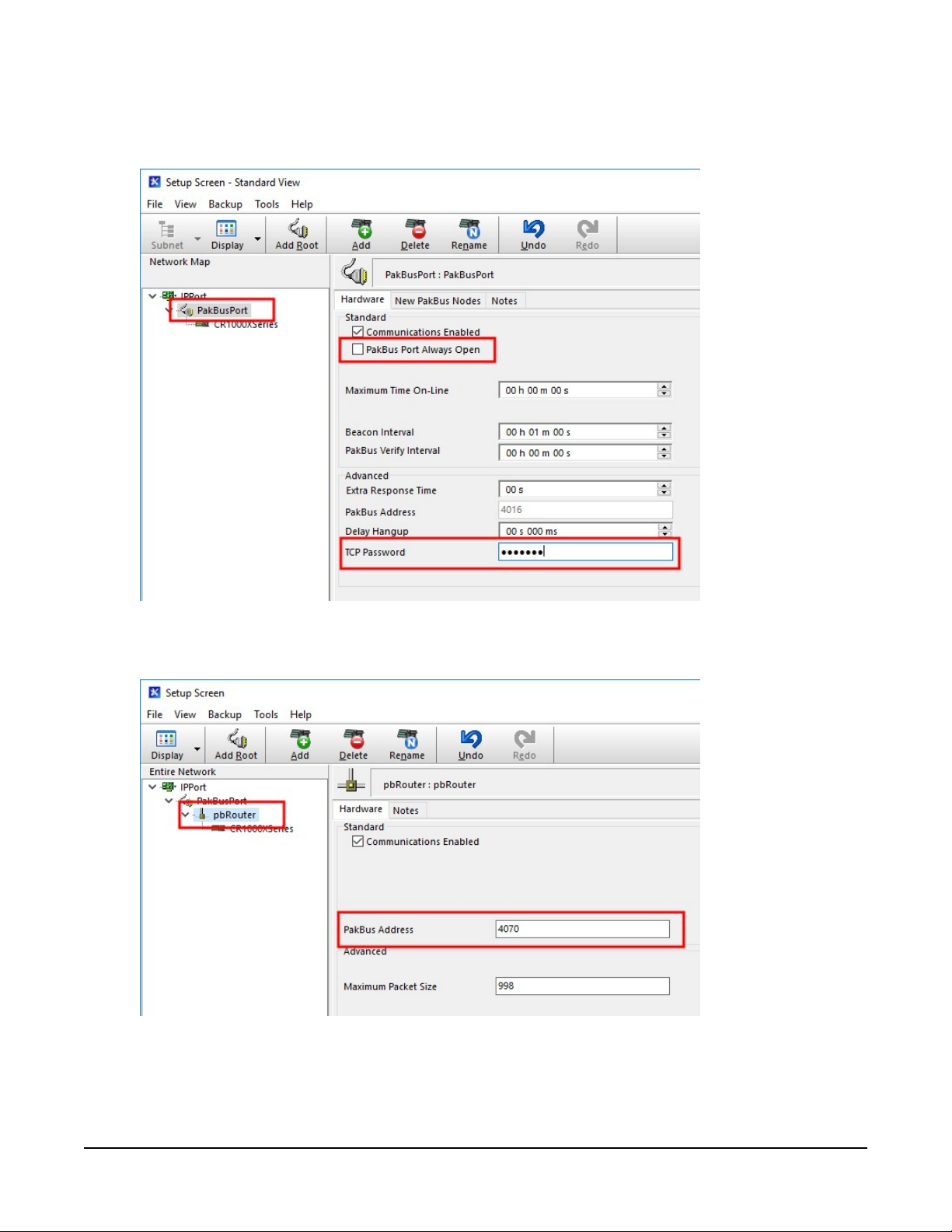
5. For PakBus data loggers, leave the default settings for the PakBusPort. PakBus Port Always
Open should not be checked. Enter the TCP Password; this must match the value entered
in the Konect PakBus Router setup and LoggerNet setup.
6. For PakBus data loggers, select the pbRouter in the Network Map and set the PakBus
Address to 4070.
CELL200-Series 4G LTE Cellular Module 14
Page 19
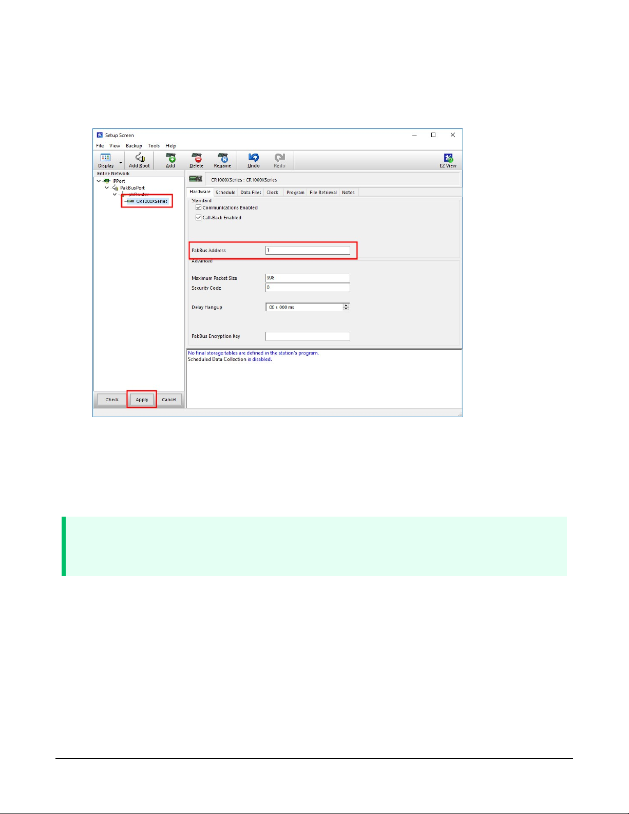
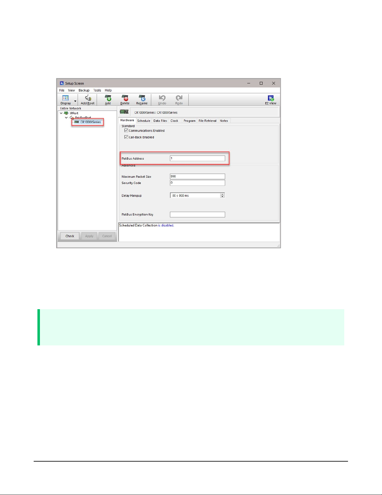
7. For PakBus data loggers, select the data logger in the Network Map and set the PakBus
Address to match that of the data logger (default address in the data logger is 1). If a
PakBus Encryption Key was entered during data logger setup, also enter it here. Click Apply
to save the changes.
4.1.4 Test the connection
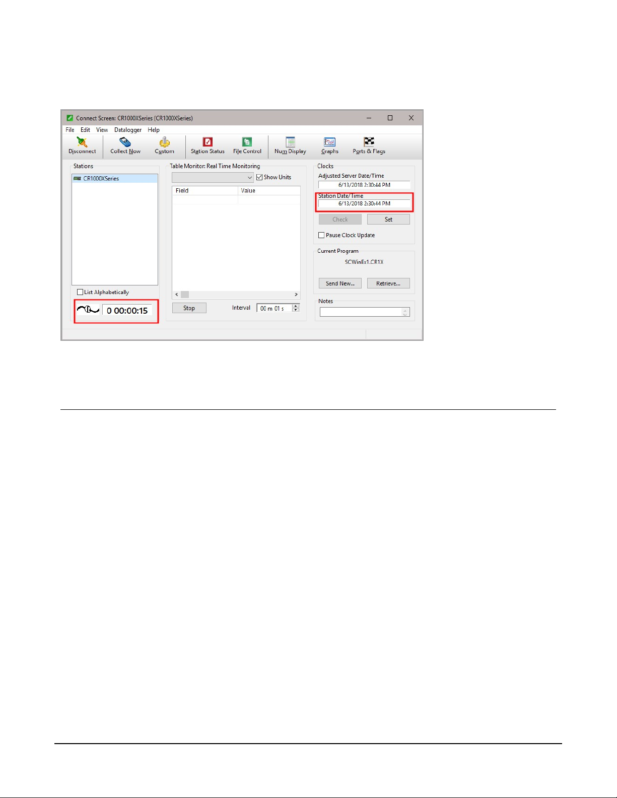
After the Network Map has been configured, test the cellular connection by using the Connect
screen as shown in the following image. Click on the appropriate station and click Connect to
initiate a call to the data logger.
TIP:
The connection time is subject to many external factors. It is often less than 30 seconds but
could be up to fifteen minutes. Be patient.
CELL200-Series 4G LTE Cellular Module 15
Page 20

If the call is successful, the connectors at the bottom of the screen will come together and clock
information from the data logger will be displayed in the Station Date/Time field. If the
connection fails, a Communications Failure message will be displayed.
4.2 Modules using a public static IP
4.2.1 Set up hardware
1. Connect the Cellular antenna.
2. Connect your data logger to the CELL200-series module RS-232 or CS I/O port. See Wiring
and connections (p. 25).
3. If not connecting through CS I/O, provide power to the CELL200 series.
4.2.2 Configure data logger
1. Connect to your data logger by using Device Configuration Utility.
2. On the PPP tab, set Config/Port Used to CS I/O SDC8 or RS-232, depending on how you
are connected to the data logger.
3. Verify the Modem Dial String setting is blank.
4. If connecting through RS-232, on the Comport Settings tab, set RS232 BaudRate to 115200
Fixed.
CELL200-Series 4G LTE Cellular Module 16
Page 21
5. On the Cellular tab, enter the APN provided by your cellular provider.
6. (Optional) By default, the CELL200 series will accept incoming communications from any IP
address. This can be a security risk. You may specify up to four IP addresses, with wild cards,
to limit connections to only those trusted sources. Use an asterisk (*) as a wild card. For
example, a setting of 166.22.*.* would allow connections from devices that have IP
addresses starting with 166.22. Both IPv4 and IPv6 addresses are supported.
CAUTION:
Only set a Trusted IP address if you are familiar with their use. Consult your IT
department or Campbell Scientific for assistance.
NOTE:
This setting does not affect outbound connections, only incoming connections.
CELL200-Series 4G LTE Cellular Module 17
Page 22
In the Device Configuration Utility go to the Settings Editor then Network Services. Next to
the Trusted Hosts field, click Edit and Add your trusted IP addresses, one at a time.
7. Click Apply to save the changes.
4.2.3 Set up LoggerNet
The LoggerNet Network Map is configured from the LoggerNet Setup screen.
NOTE:
Setup has two options, EZ (simplified) and Standard. Click on the View menu at the top of
the Setup screen, and select Standard view.
From the LoggerNet toolbar, click Main > Setup and configure the Network Map as described in
the following steps:
1. Select Add Root > IPPort.
2. Select PakBusPort
3. Add a data logger to the PakBusPort.
CELL200-Series 4G LTE Cellular Module 18
Page 23
4. Select the IPPort in the Network Map. Enter the CELL200 series IP address and port number.
The IP address and port number are input in the Internet IP Address field separated by a
colon. Preceding zeros are not entered in the Internet IP Address (for example,
070.218.074.247 is entered as 70.218.74.247). The default port number is 6785.
5. For PakBus data loggers, leave the default settings for the PakBusPort. PakBus Port Always
Open should not be checked. If used, enter the TCP Password.
CELL200-Series 4G LTE Cellular Module 19
Page 24
6. For PakBus data loggers, select the data logger in the Network Map and set the PakBus
Address to match that of the data logger (default address in the data logger is 1). If a
PakBus Encryption Key was entered during data logger setup, also enter it here. Click Apply
to save the changes.
4.2.4 Test the connection
After the Network Map has been configured, test the cellular connection by using the Connect
screen as shown in the following image. Click on the appropriate station and click Connect to
initiate a call to the data logger.
TIP:
The connection time is subject to many external factors. It is often less than 30 seconds but
could be up to fifteen minutes. Be patient.
CELL200-Series 4G LTE Cellular Module 20
Page 25
If the call is successful, the connectors at the bottom of the screen will come together and clock
information from the data logger will be displayed in the Station Date/Time field. If the
connection fails, a Communications Failure message will be displayed.
5. Specifications
Data Logger Compatibility
The CELL200 series is compatible with the CR1000X, CR300 series, CR6 series, CR1000, CR3000,
CR800 series, CR200(X) series, CR5000, CR10X, CR10X-PB, CR510, CR510-PB, CR23X, and
CR23X-PB. See Module communications connections (p. 26) for information on communication
options with each data logger model.
Cellular WAN
See
https://s.campbellsci.com/documents/us/miscellaneous/Cellular%20Modem%20Frequency%20B
ands.pdf for a complete list of supported frequency bands.
Host Interfaces
l CS I/O communications port, DB9 male
l RS-232 serial port, DB9 female
l USB version 2.0 with micro-B connector
CELL200-Series 4G LTE Cellular Module 21
Page 26

RF Connectors
l 2 SMA antenna connectors (primary and diversity)
Power
l Operating Voltage: 10 to 30 VDC
l Low Power Mode:300 μA
l Typical Idle: 14 mA @ 12 VDC
l Typical Active: 39 mA @ 12 VDC (CELL205, CELL215, CELL220, CELL225)
25 mA @ 12 VDC (CELL210)
Size
l Dimensions: 13.46 X 8.1 X 2.86 cm (5.3 X 3.19 X 1.13 in)
l Weight: 215.5 g (7.6 oz)
Environmental
l Operating Temperature Range: –40 to 80 °C
l Storage Temperature: –45 to 80 °C
l Humidity: 10 to 90%
Industry Certifications
l Environmental: RoHS
SIM (Subscriber Identity Module) card interface
l Micro-SIM (3FF) (6 position / contacts)
l Supports SIMs that require 1.8 or 3 VDC
Data Speeds
l LTE: Max 10 Mbps (download) / Max 5 Mbps (upload)
l WCDMA: Max 384 Kbps (download) / Max 384 Kbps (upload)
l GSM
o
EDGE: Max 296 Kbps (download) / Max 236.8 Kbps (upload)
o
GPRS: Max 107 Kbps (download) / Max 85.6 Kbps (upload)
Compliance
l Industry Canada (IC): 10224A-201611EC21A
l View Declaration of Conformity at:
www.campbellsci.com/cell205
www.campbellsci.com/cell210
CELL200-Series 4G LTE Cellular Module 22
Page 27

www.campbellsci.com/cell215
www.campbellsci.com/cell220
www.campbellsci.com/cell225
6. Installation
6.1 Base station requirements 23
6.2 Data logger site equipment 23
6.3 Wiring and connections 25
6.3.1 Module communications connections 26
6.3.2 Module power connections 28
6.3.3 Antenna connections 29
6.4 CELL200 series and data logger configuration 31
6.4.1 Integrated mode option 31
6.4.2 Non-integrated mode option 31
6.4.3 Serial server mode option 36
6.4.4 Serial client mode option 42
6.4.5 Serial server/client mode option 48
6.1 Base station requirements
A computer running Campbell Scientific LoggerNet software with access to the Internet is
needed.
6.2 Data logger site equipment
l CELL200-series module with power cable (included with module)
l Data logger — CR1000X series, CR300 series, CR6 series, CR1000, CR3000, CR800 series,
CR5000, and GRANITE 6/9/10
l Module Interface, see Module communications connections (p. 26)
l Environmental Enclosure — ENC10/12, ENC12/14, or ENC16/18
If connecting to CS I/O port:
SC12 cable (preferred for CR1000X series, CR300 series, CR6 series, CR1000, CR3000,
CELL200-Series 4G LTE Cellular Module 23
Page 28
CR800 series, CR5000, and GRANITE 6/9/10 data loggers ) — connects the module to
current data logger with a CS I/O port. See CS I/O connection (p. 27)
SC105 Interface — connects the module to any data logger with a CS I/O port. It must
be configured using Device Configuration Utility. Settings should be:
l CS I/O Mode: SDC Address 8
l CS I/O ME Baud Rate: 115.2k
l RS-232 Mode: Modem (default)
l Baud Rate:
l 115.2k fixed for CR1000X series, CR300 series, CR6 series, CR1000, CR3000,
CR800 series, CR5000, and GRANITE 6/9/10 data loggers
l 9600 for CR10X, CR10X-PB, CR510, CR510-PB, CR23X, CR23X-PB, and CR200
(X) series data loggers
l 8 data bits, 1 stop bit, no parity
If connecting to RS-232 port:
Null Modem Cable (9 pin, male-to-male) — connects the module to the CR1000X series,
CR300 series, CR1000, CR3000, CR800 series, and CR200(X) series RS-232 port.
CPI/RS-232 RJ45 to DB9 Cable — connects the module to the CR6 series or CR1000X
series CPI/RS-232 port.
l Antenna — the following antennas are available from Campbell Scientific. Contact
Campbell Scientific for help in determining the best antennas for your application.
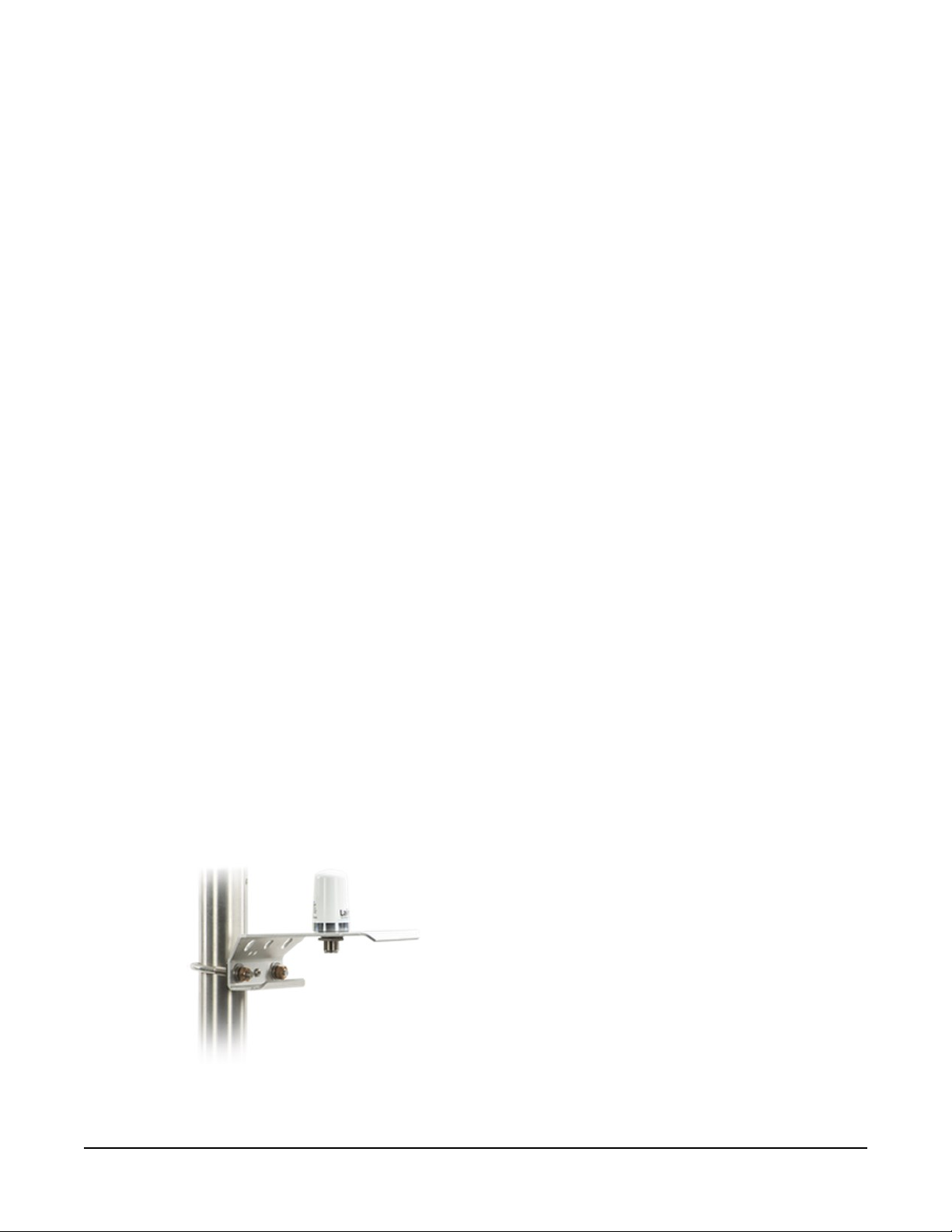
o
2 dBd 4G/3G Omnidirectional Antenna: An omnidirectional antenna with mounting
bracket that is ideally suited for use with 4G and 3G cellular gateways. The mounting
bracket attaches to a mast or crossarm, and it serves as the antenna ground plane.
The antenna has an N type (female) threaded permanent stud for easy mounting to
the included bracket or through an enclosure wall. A coaxial cable, sold separately, is
required to connect this antenna to the inline surge suppression or module antenna
jack. The antenna includes a mount/U-bolt assembly for attaching the antenna to a
mast, post, or crossarm up to 3.8 cm (1.5 in) in diameter.
CELL200-Series 4G LTE Cellular Module 24
Page 29
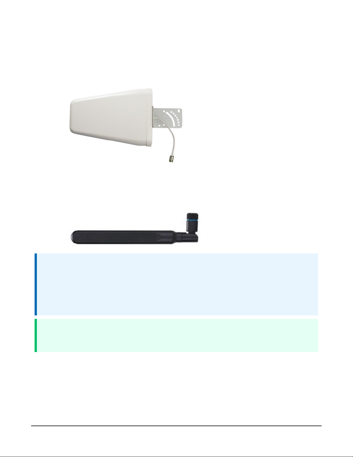
o
8 dBd Yagi Wideband Antenna: A higher gain antenna that should be “aimed” at the
service provider antenna. It covers both the 800-MHz band and the 1.9-GHz band.
The antenna comes with bracket/U-bolt assembly for attaching the antenna to a
mast or post. A coaxial cable, sold separately, is required to connect this antenna to
the inline surge suppression or module antenna jack. This antenna is recommended
for areas that require a higher gain antenna.
o
4G/3G Cellular Whip Antenna with SMA Connector: A wideband termination
antenna with SMA connector and articulating base. This antenna is intended for
short-term testing use only. It is not intended for long-term use. Campbell Scientific
recommends that customers use external antennas for the best reception and
transmission of cellular signals.
NOTE:
When antennas are located away from the CELL200 series, keep the cables as short as
possible to prevent the loss of antenna gain. Route the cables to protect them from damage
and so they will not be snagged or pulled on. Avoid binding or sharp corners in the cable
routing. Bundle and tie off excess cable. Make sure the cables are secured so their weight will
not loosen the connector from the CELL200 series over time.
TIP:
Cellular phone apps, such as OpenSignal (https://opensignal.com/), show the direction to
point an antenna to get the best signal strength.
6.3 Wiring and connections
This section explains how to connect the module for different communications methods. It also
describes how to power the module and connect an antenna.
CELL200-Series 4G LTE Cellular Module 25
Page 30

6.3.1 Module communications connections
The following table shows communications options for each Campbell Scientific data logger
model.
Table 6-1: CELL200 series data logger compatibility chart
Data logger model
Connecting to CELL200 series
CR300 N/A
CR310 N/A
CR6
(PPP and serial server)
CR1000X
(PPP and serial server)
CR200(X) N/A
via CS I/O port
SC12 CS I/O cable
SC12 CS I/O cable
Connecting to CELL200 series
via RS- 232 port
RS-232 null modem cable, or
C-port to RS-232 cable
(PPP or serial server)
RS-232 null modem cable, or
C-port to RS-232 cable
(PPP or serial server)
CPI/RS-232 cable, or
C- or U-port to RS-232 cable, or
SC105 CS I/O to RS-232 adapter
CPI/RS-232 cable, or
C-port to RS-232 cable, or
SC105 CS I/O to RS-232 adapter
RS-232 null modem cable
(serial server only)
CR800
SC12 CS I/O cable
(PPP and serial server)
SC12 CS I/O cable
CR1000
(PPP and serial server)
SC12 CS I/O cable
CR3000
(PPP and serial server)
CR5000 N/A
RS-232 null modem cable
(PPP or serial server), or
C-port to RS-232 cable, or
SC105 CS I/O to RS-232 adapter
RS-232 null modem cable
(PPP or serial server), or
C-port to RS-232 cable, or
SC105 CS I/O to RS-232 adapter
RS-232 null modem cable
(PPP or serial server), or
C-port to RS-232 cable, or
SC105 CS I/O to RS-232 adapter
RS-232 null modem cable
(serial server only)
CELL200-Series 4G LTE Cellular Module 26
Page 31

Table 6-1: CELL200 series data logger compatibility chart
Data logger model
CR510andCR10X N/A SC105 CS I/O to RS-232 adapter
CR510-PBandCR10X-PB
CR23X N/A
CR23X-PB
FIGURE 6-1 (p. 27), FIGURE 6-2 (p. 28), and FIGURE 6-3 (p. 28) illustrate the most common
communication connections between a data logger and a CELL200 series.
Connecting to CELL200 series
via CS I/O port
SC12 CS I/O cable
(serial server only)
(SDC7 and SDC8 only)
SC12 CS I/O cable
(serial server only)
(SDC7 and SDC8 only)
CS I/O connection using an SC12 cable
Connecting to CELL200 series
via RS- 232 port
SC105 CS I/O to RS-232 adapter
RS-232 null modem cable
(serial server only), or
SC105 CS I/O to RS-232 adapter
RS-232 null modem cable
(serial server only), or
SC105 CS I/O to RS-232 adapter
The SC12 is used to connect the module to a data logger CS I/O port.
FIGURE 6-1. CS I/O connection
CELL200-Series 4G LTE Cellular Module 27
Page 32

RS-232 connection using a null modem cable
Null Modem Cable is used to connect the module to the CR3000, CR800, CR2XX, CR300
series, or CR1000 RS-232 port. Power is provided from the 12V or SW12V port of the data
logger.
FIGURE 6-2. RS-232 connection
CR1000X or CR6 RS-232 connection using a CPI/RS-232 cable
RS-232/CPI RJ45 to DB9 Male DTE is used to connect the module to the CR6 or CR1000X.
Power is provided from the 12V or SW12V port of the data logger.
FIGURE 6-3. CR6/CR1000X RS-232 connection
6.3.2 Module power connections
When connecting through the CS I/O port, power for the module is provided by the data logger.
When connecting through the RS-232 port, power must be supplied through the Power In
connector.
Controlling power to the CELL200 series (p. 58) provides an example CRBasic program using the
IPNetPower() instruction to control power to the CELL200 series. This functionality is
available in the CR300 series (all operating systems), the CR6 series with operating system 09.00
or greater, and the CR1000X with operating system 03.00 or greater. To control power in these
data loggers with older operating systems or any CR1000, CR800 series, or CR3000, you will need
to use a SW12V port on the data logger and communicate over RS-232.
Alternatively, CR1000X series, CR300 series, CR6 series, CR1000, CR3000, CR800 series, CR5000,
and GRANITE 6/9/10 can use terminal commands to control power. Search for "deep sleep"
and "wakeup" in Using cell modem terminal functionality (p. 65). CR1000, CR800 series, and
CELL200-Series 4G LTE Cellular Module 28
Page 33

CR3000 CRBasic programs require PPPClose before the "deep sleep" command and
PPPOpen before the "wakeup" command.
The USB port provides power for module configuration, but is not sufficient for normal
operation.
6.3.3 Antenna connections
Use of a diversity antenna can improve system performance. It is required in 4G networks, but not
2G or 3G.
FIGURE 6-4. Antenna connections
1. Connect the cellular antenna to the Primary Antenna connector. Mount the cellular
antenna so there is at least 20 cm between the antenna and the user or any bystander.
2. Connect a second antenna, if used, to the Diversity Antenna connector.
Antenna diversity, also called space diversity, is a scheme that uses two or more antennas to
improve the quality and reliability of a wireless link. Often, especially in urban and indoor
environments, there is no clear line of sight between transmitter and receiver. Instead, the signal
is reflected along multiple paths before finally being received. Each bounce can introduce phase
shifts, time delays, attenuations, and distortions that can destructively interfere with one another
at the aperture of the receiving antenna. Diversity-antenna-capable devices support multiple
antennas (usually two) in order to combat this phenomenon and minimize its effects.
CELL200-Series 4G LTE Cellular Module 29
Page 34

Diversity antennas are not required for 2G/3G connections; however, they are highly
recommended in order to get the most reliable connection, especially in areas of low coverage.
Identical or very similar antennas should also be used for the best results.
For 4G networks, the second antenna operates as a MIMO (multiple input, multiple output )
antenna, providing a second receive path and a second transmit path. This connection is
required for operation on 4G/LTE networks.
Table 6-2: Recommended antenna separation
Service
Frequency
(MHz)
LTE 700 428 214 107
LTE 800 375 187 94
LTE 900 333 167 83
LTE 1800 167 83 42
LTE 2100 143 71 36
LTE 2600 115 58 29
WCDMA 850 353 176 88
WCDMA 900 333 167 83
WCDMA 1900 158 79 39
WCDMA 2100 143 71 36
CDMA/EV-DO 800 375 187 94
Wavelength (λ)
(mm)
Best antenna
separation (mm)
(1/2 λ)
Good antenna
separation (mm)
(1/4 λ)
CDMA/EV-DO 1900 158 79 39
GSM/GPRS/EDGE 850 353 176 88
GSM/GPRS/EDGE 900 333 167 83
GSM/GPRS/EDGE 1800 167 83 42
GSM/GPRS/EDGE 1900 158 79 39
WARNING:
Antenna may not exceed the maximum gain specified in RF exposure (p. 87).
In more complex installations, such as those requiring long cable lengths or multiple
connections, you must follow the maximum dBi gain guidelines specified by the radio
CELL200-Series 4G LTE Cellular Module 30
Page 35

communications regulations of the Federal Communications Commission (FCC), Industry
Canada, or your country's regulatory body.
6.4 CELL200 series and data logger configuration
NOTE:
Instructions in this section assume that the steps in Pre-installation (p. 2) have been
completed. Cellular service must be setup before web access using
www.cell.linktodevice.com/ is available.
Select the installation option that best suits your application. The Overview (p. 7) section
describes the differences.
6.4.1 Integrated mode option 31
6.4.2 Non-integrated mode option 31
6.4.3 Serial server mode option 36
6.4.4 Serial client mode option 42
6.4.5 Serial server/client mode option 48
6.4.1 Integrated mode option
QuickStart (integrated mode) (p. 8) describes setting up the CELL200 series in integrated mode
with its default settings.
If the module is not in its default settings, the settings in the CELL200 series must match those in
the data logger for integrated mode to work. This includes the SDC Address for CS I/O
communication or the RS-232 Baud Rate for RS 232 communication. Once these settings match,
all other configuration changes can be done in the data logger as described in QuickStart
(integrated mode) (p. 8).
See Non-integrated mode option (p. 31) for information on changing these settings in the
CELL200 series and data logger.
6.4.2 Non-integrated mode option
In non-integrated mode, the module mimics the behavior of our older cellular modems. This
mode should be used when doing a direct replacement of a Raven or an RV50 modem.
CELL200-Series 4G LTE Cellular Module 31
Page 36

6.4.2.1 Configure CELL200 series
1. Connect a USB cable between your module and computer.
2. Connect the Cellular antenna.
3. Connect the Diversity antenna, if used. (Not required. See Antenna connections (p. 29).)
4. Open a web browser and go to: www.cell.linktodevice.com/.
TIP:
If your computer does not respond to the DNS server correctly, browse to 192.168.86.1.
5. On the Settings tab, enter the APN provided by your cellular provider.
6. If you will be connecting through CS I/O, select the desired SDC Address.
7. If you will be connecting through RS-232, select the desired RS232 Baud Rate.
6.4.2.2 Configure data logger
1. Connect to your data logger using Device Configuration Utility.
2. If using the Konect PakBus Router:
a. On the Datalogger tab, change the data logger PakBus Address and optional
PakBus/TCP Password to match the values entered in the Konect PakBus Router
setup.
b. On the Network Services tab in the PakBus/TCP Client field, enter the DNS address
and Port number noted during the Konect PakBus Router setup.
3. On the PPP tab, set Config/Port Used to the CS I/O SDC address selected in the module or
RS-232 depending on how you will be connected to the data logger.
4. Verify the Modem Dial String setting is blank.
5. (Optional) If using CS I/O communication, the throughput can be enhanced by changing
the SDC Baud Rate from 115200 to 460800. On the Advanced tab, set the SDC Baud Rate to
460800. Note that if there are other devices on the CS I/O port, they all must be able to
support this higher baud rate.
6.4.2.3 Set up hardware
1. Connect the Cellular antenna.
2. Connect your data logger to the CELL200-series module RS-232 or CS I/O port. See Wiring
CELL200-Series 4G LTE Cellular Module 32
Page 37

and connections (p. 25).
3. If not connecting through CS I/O, provide power to the CELL200 series.
6.4.2.4 Set up LoggerNet
The LoggerNet Network Map is configured from the LoggerNet Setup screen.
NOTE:
Setup has two options, EZ (simplified) and Standard. Click on the View menu at the top of
the Setup screen, and select Standard view.
From the LoggerNet toolbar, click Main > Setup and configure the Network Map as described in
the following steps:
1. Select Add Root > IPPort.
2. Select PakBusPort and pbRouter for PakBus data loggers such as the CR1000X or CR300.
3. Add a data logger to the pbRouter.
4. Select the IPPort in the Network Map. Enter the CELL200 series IP address (public static IP)
or the Konect PakBus Router DNS address (private dynamic IP), along with the port
number. The address and port number are input in the Internet IP Address field separated
by a colon. Preceding zeros are not entered (for example, 070.218.074.247 is entered as
70.218.74.247). When not using Konect, the default port number is 6785.
CELL200-Series 4G LTE Cellular Module 33
Page 38

5. For PakBus data loggers, leave the default settings for the PakBusPort. PakBus Port Always
Open should not be checked. Enter the TCP Password; this must match the value entered
in the Konect PakBus Router setup and LoggerNet setup.
6. For PakBus data loggers, select the pbRouter in the Network Map and set the PakBus
Address to 4070.
CELL200-Series 4G LTE Cellular Module 34
Page 39

7. For PakBus data loggers, select the data logger in the Network Map and set the PakBus
Address to match that of the data logger (default address in the data logger is 1). If a
PakBus Encryption Key was entered during data logger setup, also enter it here. Click Apply
to save the changes.
6.4.2.5 Test the connection
After the Network Map has been configured, test the cellular connection by using the Connect
screen as shown in the following image. Click on the appropriate station and click Connect to
initiate a call to the data logger.
TIP:
The connection time is subject to many external factors. It is often less than 30 seconds but
could be up to fifteen minutes. Be patient.
CELL200-Series 4G LTE Cellular Module 35
Page 40

If the call is successful, the connectors at the bottom of the screen will come together and clock
information from the data logger will be displayed in the Station Date/Time field. If the
connection fails, a Communications Failure message will be displayed.
6.4.3 Serial server mode option
In serial server mode, the module receives IP communications over the cellular network and
converts those to serial communications to pass on to the data logger. From the perspective of
the data logger, this is no different than a serial cable connecting it to a computer.
This is the mode used with CR200-Series and Edlog (CR23X, CR10X, and CR510) data loggers, and
cellular-to-RF networks. Only one IP connection at a time is supported.
NOTE:
A public static IP account must be used when the module is set up in serial server mode.
Private dynamic IP accounts do not support the serial server mode.
NOTE:
Instructions in this section assume that you have established cellular service and the SIM card
has been installed as described in QuickStart (integrated mode) (p. 8).
6.4.3.1 Configure CELL200 series
To set up the CELL200 series in serial server mode:
1. Connect a USB cable between your module and computer.
2. Connect the Cellular antenna.
CELL200-Series 4G LTE Cellular Module 36
Page 41

3. Connect the Diversity antenna, if used. (Not required. See Antenna connections (p. 29).)
4. Open a web browser and go to: www.cell.linktodevice.com/.
TIP:
If your computer does not respond to the DNS server correctly, browse to 192.168.86.1.
5. On the Settings tab, enter the APN provided by your cellular provider.
6. Set Mode to Serial Server.
7. Set Serial Server Listen Port Number. (Default is 3001. This is entered along with the IP
address as part of the LoggerNet configuration.)
8. (Optional) In this mode, an Automated Power Schedule can be setup to save on battery life
or on cellular charges. Go to the Settings then Serial Mode Setup tab. Enter a Start (poweron) Time, On Duration, and Repeat Cycle.
For example: With the following settings of Start (power-on) Time of 22:00, On Duration of
10 minutes, and Repeat Cycle of Every Hour the cellular module will turn on for ten minutes
CELL200-Series 4G LTE Cellular Module 37
Page 42

only twice each day. It will turn on at 10:00 pm and 11:00 pm. It will not turn on at midnight
since it is powered off at the start of the next day.
9. (Optional) By default, the CELL200 series will accept incoming communications from any IP
address. This can be a security risk. You may specify up to four IP addresses, with wild cards,
to limit connections to only those trusted sources. Use an asterisk (*) as a wild card. For
example, a setting of 166.22.*.* would allow connections from devices that have IP
addresses starting with 166.22. Both IPv4 and IPv6 addresses are supported.
CAUTION:
Only set a Trusted IP address if you are familiar with their use. Consult your IT
department or Campbell Scientific for assistance.
NOTE:
This setting does not affect outbound connections, only incoming connections.
Go to the Settings then Advanced tab. Enter your trusted IP addresses, one per line, in the
Trusted IP Host Addresses box.
CELL200-Series 4G LTE Cellular Module 38
Page 43

10. (Optional, for modules with static IP addresses.) To get remote access to the module you
must first set up a User Account. For security purposes there is no default account. Select
Settings > User Accounts > Logon > Create a new Account. Provide Name, Password, and
select the Permission Level. Close then Apply Changes.
Once the module has an account it can be accessed remotely using its static IP address.
Type the IP address into a web browser to be prompted for the user name and password.
6.4.3.2 Configure data logger
1. Connect to your data logger by using Device Configuration Utility.
2. On the PPP tab, set Config/Port Used to Inactive.
3. When using RS-232 serial server mode, it is recommended that you use a fixed baud rate
on the data logger RS-232 port. On the Com Ports Settings tab, select the RS-232 port and
set the Baud Rate to the fixed option to match the RS 232 baud rate set in the CELL200series module.
4. If using CS I/O communication, the throughput can be enhanced by changing the SDC
Baud Rate from 115200 to 460800. On the Advanced tab, set the SDC Baud Rate to 460800.
Note that if there are other devices on the CSI/O port, they all must be able to support this
higher baud rate.
6.4.3.3 Set up hardware
1. Connect the Cellular antenna.
2. Connect your data logger to the CELL200-series module RS-232 or CS I/O port. See Wiring
and connections (p. 25).
3. If not connecting through CS I/O, provide power to the CELL200 series.
6.4.3.4 Set up LoggerNet
The LoggerNet Network Map is configured from the LoggerNet Setup screen.
NOTE:
Setup has two options, EZ (simplified) and Standard. Click on the View menu at the top of
the Setup screen, and select Standard view.
From the LoggerNet toolbar, click Main > Setup and configure the Network Map as described in
the following steps:
1. Select Add Root > IPPort.
2. Add a data logger to the IPPort.
CELL200-Series 4G LTE Cellular Module 39
Page 44

3. Select the IPPort in the Network Map. Enter the CELL200 series IP address (public static IP)
or the Konect PakBus Router DNS address (private dynamic IP), along with the port
number. The address and port number are input in the Internet IP Address field separated
by a colon. Preceding zeros are not entered (for example, 070.218.074.247 is entered as
70.218.74.247). For serial server mode, the default port number is 3001.
4. For PakBus data loggers, leave the default settings for the PakBusPort. PakBus Port Always
Open; it should not be checked. If used, enter the TCP Password.
CELL200-Series 4G LTE Cellular Module 40
Page 45

5. For PakBus data loggers, select the data logger in the Network Map and set the PakBus
Address to match that of the data logger (default address in the data logger is 1). Click
Apply to save the changes.
6.4.3.5 Test the connection
After the Network Map has been configured, test the cellular connection by using the Connect
screen as shown in the following image. Click on the appropriate station and click Connect to
initiate a call to the data logger.
TIP:
The connection time is subject to many external factors. It is often less than 30 seconds but
could be up to fifteen minutes. Be patient.
CELL200-Series 4G LTE Cellular Module 41
Page 46

If the call is successful, the connectors at the bottom of the screen will come together and clock
information from the data logger will be displayed in the Station Date/Time field. If the
connection fails, a Communications Failure message will be displayed.
6.4.4 Serial client mode option
This mode requires CELL200 series operating system 2.00 or newer. Find the CELL200 series OS
version in the OS Date field of the Status Tab. For more information, see Updating the operating
system and firmware (p. 81).
In serial client mode the module will connect to the cellular network and initiate a TCP client
socket connection. When data is sent to the active port (RS-232 or CS I/O) it will be sent out on
the TCP client connection. When data is received on the TCP client socket connection it is passed
to the active port (RS-232 or CS I/O).
CELL200-Series 4G LTE Cellular Module 42
Page 47

Use this mode when the module is behind a cellular provider firewall and it has a privatedynamic
IP address. This mode requires the receiving TCP/IP connection be on a public static IP address,
on the same private cellular network, DNSname or there be a hole in the firewall.
NOTE:
Instructions in this section assume that you have established cellular service and the SIM card
has been installed as described in QuickStart (integrated mode) (p. 8).
6.4.4.1 Configure CELL200 series
To set up the CELL200 series in serial server mode:
1. Connect a USB cable between your module and computer.
2. Connect the Cellular antenna.
3. Connect the Diversity antenna, if used. (Not required. See Antenna connections (p. 29).)
4. Open a web browser and go to: www.cell.linktodevice.com/.
TIP:
If your computer does not respond to the DNS server correctly, browse to 192.168.86.1.
5. On the Settings tab, enter the APN provided by your cellular provider.
6. On the General tab, set Mode to Serial Client.
CELL200-Series 4G LTE Cellular Module 43
Page 48

7. Select the Serial Mode Setup tab.
8. Enter the URL and Port Number of the server/device that the module will connect to.
9. (Optional) Select Always Open for the Timeout .
CELL200-Series 4G LTE Cellular Module 44
Page 49

10. (Optional) In this mode, an Automated Power Schedule can be setup to save on battery life
or on cellular charges. Go to the Settings then Serial Mode Setup tab. Enter a Start (poweron) Time, On Duration, and Repeat Cycle.
For example: With the following settings of Start (power-on) Time of 22:00, On Duration of
10 minutes, and Repeat Cycle of Every Hour the cellular module will turn on for ten minutes
only twice each day. It will turn on at 10:00 pm and 11:00 pm. It will not turn on at midnight
since it is powered off at the start of the next day.
6.4.4.2 Configure data logger (optional)
SendVariables() is used to initiate a data logger call-back attempt to a computer running
LoggerNet. It has the following syntax:
SendVariables (ResultCode, ComPort, NeighborAddr, PakBusAddr, Security, TimeOut,
"TableName", "FieldName", Variable, Swath )
The ComPort needs to be set to ComRS232 or ComSDC8 depending on how you have the
module connected to the data logger. Set the TableName to "Public" and the FieldName
CELL200-Series 4G LTE Cellular Module 45
Page 50

to "Callback". The remaining parameters in the instruction are ignored. The resulting instruction
will look similar to:
SendVariables (SendResult, COMRS232, 0, 4094, 0000, 0, "Public", "Callback",
Scratch, 1)
After LoggerNet receives the variable "Callback" it will begin collecting data from the data logger
and store it to a file based on the data collection settings in the Setup window. See the CRBasic
help for more information.
6.4.4.3 Set up hardware
1. Connect the Cellular antenna.
2. Connect your data logger to the CELL200-series module RS-232 or CS I/O port. See Wiring
and connections (p. 25).
3. If not connecting through CS I/O, provide power to the CELL200 series.
6.4.4.4 Set up LoggerNet
The LoggerNet Network Map is configured from the LoggerNet Setup screen.
NOTE:
Setup has two options, EZ (simplified) and Standard. Click on the View menu at the top of
the Setup screen, and select Standard view.
From the LoggerNet toolbar, click Main > Setup and configure the Network Map as described in
the following steps:
1. Select Add Root > PakBusTcpServer.
2. Add a data logger to the PakBusTcpServer.
CELL200-Series 4G LTE Cellular Module 46
Page 51

3. Select the PakBusTcpServer in the Network Map. Select PakBus Port Always Open; the box
should have a check.
.
4. Select the data logger in the Network Map. Select Call-Back Enabled; the box should have
a check.
6.4.4.5 Test the connection
After the Network Map has been configured, test the cellular connection by using the Connect
screen as shown in the following image. Click on the appropriate station and click Connect to
initiate a call to the data logger.
TIP:
The connection time is subject to many external factors. It is often less than 30 seconds but
could be up to fifteen minutes. Be patient.
CELL200-Series 4G LTE Cellular Module 47
Page 52

If the call is successful, the connectors at the bottom of the screen will come together and clock
information from the data logger will be displayed in the Station Date/Time field. If the
connection fails, a Communications Failure message will be displayed.
6.4.5 Serial server/client mode option
This mode requires CELL200 series operating system 2.00 or newer. Find the CELL200 series OS
version in the OS Date field of the Status Tab. For more information, see Updating the operating
system and firmware (p. 81).
In serial server/client mode the module connects to the cellular network and opens a listening
port. When a client connects to the listening port, the CELL200 series will be in "serial server"
mode. In serial server mode, all data on the active port (RS-232 or CS I/O) will be routed through
the listening port. When no client is connected to the listening port, the CELL200 series will be in
"serial client" mode and all data on the active port will be sent and received through the initiated
TCP client socket connection.
CELL200-Series 4G LTE Cellular Module 48
Page 53

The incoming connection, or serial server mode, takes precedence. An outbound, or client,
connection will be interrupted if a connection is made on the incoming, or server, listening port.
NOTE:
Instructions in this section assume that you have established cellular service and the SIM card
has been installed as described in QuickStart (integrated mode) (p. 8).
6.4.5.1 Configure CELL200 series
To set up the CELL200 series in serial server mode:
1. Connect a USB cable between your module and computer.
2. Connect the Cellular antenna.
3. Connect the Diversity antenna, if used. (Not required. See Antenna connections (p. 29).)
4. Open a web browser and go to: www.cell.linktodevice.com/.
TIP:
If your computer does not respond to the DNS server correctly, browse to 192.168.86.1.
5. On the Settings tab, enter the APN provided by your cellular provider.
6. On the General tab, set Mode to Serial Server/Client.
CELL200-Series 4G LTE Cellular Module 49
Page 54

7. Select the Serial Mode Setup tab.
8. Set Server (Listening) Port Number. (Default is 3001. This is entered along with the IP
address as part of the LoggerNet configuration.)
9. Enter the URL and Port Number that the module will connect with.
10. (Optional) Select Always Open for the Timeout .
CELL200-Series 4G LTE Cellular Module 50
Page 55

11. (Optional) In this mode, an Automated Power Schedule can be setup to save on battery life
or on cellular charges. Go to the Settings then Serial Mode Setup tab. Enter a Start (poweron) Time, On Duration, and Repeat Cycle.
For example: With the following settings of Start (power-on) Time of 22:00, On Duration of
10 minutes, and Repeat Cycle of Every Hour the cellular module will turn on for ten minutes
only twice each day. It will turn on at 10:00 pm and 11:00 pm. It will not turn on at midnight
since it is powered off at the start of the next day.
CELL200-Series 4G LTE Cellular Module 51
Page 56

12. (Optional) By default, the CELL200 series will accept incoming communications from any IP
address. This can be a security risk. You may specify up to four IP addresses, with wild cards,
to limit connections to only those trusted sources. Use an asterisk (*) as a wild card. For
example, a setting of 166.22.*.* would allow connections from devices that have IP
addresses starting with 166.22. Both IPv4 and IPv6 addresses are supported.
CAUTION:
Only set a Trusted IP address if you are familiar with their use. Consult your IT
department or Campbell Scientific for assistance.
NOTE:
This setting does not affect outbound connections, only incoming connections.
Go to the Settings then Advanced tab. Enter your trusted IP addresses, one per line, in the
Trusted IP Host Addresses box.
6.4.5.2 Configure data logger
1. Connect to your data logger by using Device Configuration Utility.
2. On the PPP tab, set Config/Port Used to Inactive.
CELL200-Series 4G LTE Cellular Module 52
Page 57

3. When using RS-232 serial server mode, it is recommended that you use a fixed baud rate
on the data logger RS-232 port. On the Com Ports Settings tab, select the RS-232 port and
set the Baud Rate to the fixed option to match the RS 232 baud rate set in the CELL200series module.
4. If using CS I/O communication, the throughput can be enhanced by changing the SDC
Baud Rate from 115200 to 460800. On the Advanced tab, set the SDC Baud Rate to 460800.
Note that if there are other devices on the CSI/O port, they all must be able to support this
higher baud rate.
6.4.5.3 Set up hardware
1. Connect the Cellular antenna.
2. Connect your data logger to the CELL200-series module RS-232 or CS I/O port. See Wiring
and connections (p. 25).
3. If not connecting through CS I/O, provide power to the CELL200 series.
6.4.5.4 Set up LoggerNet
The LoggerNet Network Map is configured from the LoggerNet Setup screen.
NOTE:
Setup has two options, EZ (simplified) and Standard. Click on the View menu at the top of
the Setup screen, and select Standard view.
From the LoggerNet toolbar, click Main > Setup and configure the Network Map as described in
the following steps:
1. Select Add Root > PakBusTcpServer.
2. Add a data logger to the PakBusTcpServer.
CELL200-Series 4G LTE Cellular Module 53
Page 58

3. Select the PakBusTcpServer in the Network Map. Select PakBus Port Always Open; the box
should have a check.
.
4. Select the data logger in the Network Map. Select Call-Back Enabled; the box should have
a check.
6.4.5.5 Test the connection
After the Network Map has been configured, test the cellular connection by using the Connect
screen as shown in the following image. Click on the appropriate station and click Connect to
initiate a call to the data logger.
TIP:
The connection time is subject to many external factors. It is often less than 30 seconds but
could be up to fifteen minutes. Be patient.
CELL200-Series 4G LTE Cellular Module 54
Page 59

If the call is successful, the connectors at the bottom of the screen will come together and clock
information from the data logger will be displayed in the Station Date/Time field. If the
connection fails, a Communications Failure message will be displayed.
7. Operation and maintenance
7.1 Ports
The CS I/O port is the main port used with Campbell Scientific data loggers. Its function is
described throughout this manual.
The RS-232 port can also be used with Campbell Scientific data loggers through a null modem
cable (or CPI/RS-232 RJ45 to DB9 cable for the CR1000X and CR6 series).
The USB port is used to check the module status, configure the module, send a new operating
system, or watch low-level communications. This is done by opening a web browser and using
the following URL: www.cell.linktodevice.com/.
TIP:
If your computer does not have access to a DNS server, browse to 192.168.86.1.
CELL200-Series 4G LTE Cellular Module 55
Page 60

7.2 LED indicator lights
When your CELL200-series module is connected to power and an antenna, there is a specific
pattern to the lights to indicate its operation mode as described in LED Indicator Lights (p. 56).
Table 7-1: LED Indicator Lights
Green Blue Red
Network
Signal
Power/Traffic
Flashes every 8 seconds
when authenticated with
cellular network
Flashes every 8 seconds to
indicate good signal
strength
Flashes every 8 seconds to
indicate all is good in
network
Flashes with traffic
to/from internal cell
modem
Flashes every 8
seconds to indicate fair
signal strength
Flashes with traffic on
RS-232 or CS I/O
Flashes every 8 seconds
when issue with
network/settings
Flashes every 8 seconds to
indicate marginal or no
signal strength
Used to let user know it is in
low power state (only LED
flashing)
7.3 Signal strength
Signal strength may indicate the quality of connection to a cellular tower. For 3G networks, this is
reported as RSSl (Received Signal Strength Indicator). For 4G, it is RSRP (Reference Signal
Received Power).
Signal strength units are –dBm; –70 is a stronger signal than –100.
Table 7-2: Signal strength
Quality estimate
RSSI (3G)
dBm
Excellent -70 or greater -90 or greater
Good -71 to -85 -91 to -105
Fair -86 to 100 -106 to -115
Poor less than -100 less than -115
RSRP (4G)
dBm
CELL200-Series 4G LTE Cellular Module 56
Page 61

Because signal strength can vary due to multipath, interference, or other environmental effects, it
may not give a true indication of communication performance or range. However, it can be
useful for activities such as:
l determining the optimal direction to aim a Yagi antenna
l determining the effects of antenna height and location
l trying alternate (reflective) paths
l seeing the effect of vegetation and weather over time
CELL200-Series 4G LTE Cellular Module 57
Page 62

Appendix A. Controlling power to the CELL200 series
This example shows how to control power to the CELL200 series by using the CRBasic
IPNetPower() instruction. The program uses the TimeIsBetween() instruction to power
the CELL200 series for 15 minutes every 60 minutes between 9:00 a.m. and 5:00 p.m.
NOTE:
The IPNetPower() functionality shown in this example is available in the CR300 series
with operating system 08.00 or greater, the CR6 series with operating system 09.00 or greater,
and the CR1000X with operating system 03.00 or greater. To control power in these data
loggers with older operating systems or any CR1000, CR800 series, or CR3000, you will need to
use a SW12V port on the data logger and communicate over RS-232. When using a SW12V
port, we recommend using a PPPClose() instruction to shut down the network prior to
powering down the CELL200 series.
NOTE:
TimeIsBetween() requires operating system version 28.00 or greater in the CR1000,
CR3000, or CR800. It is supported in all CR1000X, CR6, and CR300 operating systems.
CRBasic Example 1: Turn CELL200 series ON and OFF under data logger control
'CR300 Series
'Declare Variables and Units
Public BattV
Public PTemp_C
Public ModuleState As Boolean
Units BattV=Volts
Units PTemp_C=Deg C
'Define Data Tables
DataTable(Daily,True,-1)
DataInterval(0,1440,Min,10)
Minimum(1,BattV,FP2,False,False)
EndTable
'Main Program
CELL200-Series 4G LTE Cellular Module 58
Page 63

CRBasic Example 1: Turn CELL200 series ON and OFF under data logger control
BeginProg
'Main Scan
Scan(5,Sec,1,0)
'Default Data Logger Battery Voltage measurement 'BattV'
Battery(BattV)
'Default Wiring Panel Temperature measurement 'PTemp_C'
PanelTemp(PTemp_C,60)
'Between the hours of 9:00 and 17:00, turn the CELL200 series
'on for 15 minutes at the start of every hour
If TimeIsBetween(9,17,24,Hr) AND TimeIsBetween(0,15,60,Min) Then
ModuleState=True
IPNETPower(5,1)
Else
ModuleState=False
IPNETPower(5,0)
EndIf
'Always turn OFF CELL200 series if battery drops below 11.5 volts
If BattV<11.5 Then
'Set CELL200 series power to the state of 'ModuleState' variable
IPNETPower(5,0)
EndIf
'Call Data Tables and Store Data
CallTable Daily
NextScan
EndProg
CELL200-Series 4G LTE Cellular Module 59
Page 64

Appendix B. Configuring settings and retrieving status information with the CRBasic program
B.1 Using the SetSetting() instruction
NOTE:
This functionality is available in the CR1000X, CR300-series, and CR6 dataloggers only.
This example shows how to set up the cellular module using the SetSetting() instruction. It
also illustrates how to retrieve status information from the module in the CRBasic program. This
program can be downloaded from
https://s.campbellsci.com/documents/us/miscellaneous/CELL2XX-SetSettings.dld.
CRBasic Example 2: Settings configuration and status retrieval
'CR300 Series
Public battery_voltage
Public panel_temperature_c
'cell modem diagnostic information
Public cell_todays_usage : Units cell_todays_usage = KB
Public cell_yesterdays_usage : Units cell_yesterdays_usage = KB
Public cell_this_months_usage : Units cell_this_months_usage = KB
Public cell_last_months_usage : Units cell_last_months_usage = KB
Public cell_rssi As Long : Units cell_rssi = DB
Public cell_info As String * 400
Public cell_ip_address As String * 40
Public cell_rsrp As Long
Public cell_rsrq
Public cell_ecio
Public cell_status As String * 300
Public cell_state As String * 100
CELL200-Series 4G LTE Cellular Module 60
Page 65

CRBasic Example 2: Settings configuration and status retrieval
DataTable(CELL_DIAGNOSTICS, True, -1)
Sample(1, cell_todays_usage, FP2) 'or
Sample(1, Settings.CellUsageToday, FP2)
Sample(1, cell_yesterdays_usage, FP2) 'or
Sample(1, Settings.CellUsageYesterday, FP2)
Sample(1, cell_this_months_usage, FP2) 'or
Sample(1, Settings.CellUsageMonth, FP2)
Sample(1, cell_last_months_usage, FP2) 'or
Sample(1, Settings.CellUsageLastMonth, FP2)
Sample(1, cell_rssi, IEEE4) 'or
Sample(1, Settings.CellRSSI, IEEE4)
Sample(1, cell_info, String) 'or
Sample(1, Settings.CellInfo, String)
Sample(1, cell_ip_address, String)
Sample(1, cell_rsrp, IEEE4) 'or
Sample(1, Settings.CellRSRP, IEEE4)
Sample(1, cell_rsrq, FP2) 'or
Sample(1, Settings.CellRSRQ, FP2)
Sample(1, cell_ecio, FP2) 'or
Sample(1, Settings.CellECIO, FP2)
Sample(1, cell_status, String) 'or
Sample(1, Settings.CellStatus, String)
Sample(1, cell_state, String) 'or
Sample(1, Settings.CellState, String)
EndTable
DataTable(TEST_DATA, True, -1)
DataInterval(0, 5, Min, 10)
Minimum(1, battery_voltage, FP2, True, False)
Sample(1, panel_temperature_c, FP2)
EndTable
'Main Program
BeginProg
'set up attached cell2xx module via CRBasic programming.
SetSetting("CellEnabled", True)
'Cell modem is enabled, True = enabled, False = disabled
SetSetting("CellAPN", "****.****")
'Replace *s with APN assigned by cellular provider
SetSetting("CellPwrStartTime", 1440)
'Automated start-up schedule. Setting is in minutes (into day).
'1440 = Always on. 15 = 00:15 hours, 180 = 03:00 hours, 1380 = 23:00 hours
SetSetting("CellPwrDuration", 0)
'How long the modem is to stay online after it hits it Start Time.
'Setting is ignored if CellPwrStartTime is set to 1440
SetSetting("CellPwrRepeat", 0)
CELL200-Series 4G LTE Cellular Module 61
Page 66

CRBasic Example 2: Settings configuration and status retrieval
'Specifies the interval (in minutes) after the
'first time of the day that the data logger
'powers on its cellular interface, that the
'data logger will power its cellular interface at
'subsequent times throughout the day. 0 = disabled.
SetSetting("CellBillingDay", 15)
'Tells the modem what day of the month to roll
'over its stats counters. Used to align it with
'my cellular provider’s billing dates.
SetSetting("CellDiversity", 1)
'Turns on the use of the cell modules diversity
'antenna in the cellular module. 0 = OFF. 1 = ON.
cell_ip_address = PPPOpen() 'Just make sure we are ready to go!
Scan (1,Sec,0,0)
PanelTemp (panel_temperature_c,60)
Battery (battery_voltage)
CallTable TEST_DATA
NextScan
SlowSequence
Scan (10, Min, 0, 0)
cell_rssi = Settings.CellRSSI
'read RSSI (signal strength) from tower connected to
cell_todays_usage = Settings.CellUsageToday 'usage reported in KB
cell_yesterdays_usage = Settings.CellUsageYesterday 'usage reported in KB
cell_this_months_usage = Settings.CellUsageMonth 'usage reported in KB
cell_last_months_usage = Settings.CellUsageLastMonth 'usage reported in KB
cell_info = Settings.CellInfo
'Cell Info. Same information that shows in the
'DevConfig Cellular Network Status field
cell_status = Settings.CellStatus
'Status of the cellular modem.
cell_state = Settings.CellState
'State that the modem is in. "Network ready." lets me
'know my modem is good to go.
'CellState can be the following (but not limited to):
'"Power off.",
'"Powering up.",
'"Powered up.",
'"SIM authorized.",
'"Setting baud rate.",
'"Waiting for baud rate.",
'"Baud rate set.",
'"Baud rate failure.",
'"Power off. Waiting for retry.",
CELL200-Series 4G LTE Cellular Module 62
Page 67

CRBasic Example 2: Settings configuration and status retrieval
'"Powered up. SIM auth failure.",
'"Querying modem.",
'"Waiting for network registration.",
'"Configuring modem.",
'"Dialing.",
'"Dialing (retry).",
'"Dialed.",
'"PPP negotiation.",
'"Network ready.",
'"PPP closing.",
'"PPP paused.",
'"PPP dropped.",
'"Terminal AT command mode.",
'"Firmware update mode.",
'"Shutting down."
cell_rsrp = Settings.CellRSRP
'Reference signal received power for LTE in dbm.
'Very similar to RSSI
cell_ecio = Settings.CellECIO 'Reference signal received quality for 3G.
cell_rsrq = Settings.CellRSRQ 'Reference signal received quality for 4G.
cell_ip_address = IPInfo (1, 0)
'Get the TCP/IP address of the PPP/cellular modem interface.
CallTable CELL_DIAGNOSTICS
NextScan
EndSequence
EndProg
CELL200-Series 4G LTE Cellular Module 63
Page 68

Appendix C. Cellular module terminal functionality
This appendix discusses the terminal functionality of the CELL200-series modules. This
functionality requires a data logger with a CS I/O port.
To use the terminal functionality of the module, you must enable the terminal port. To do this:
1. Connect a USB cable between your module and computer.
2. Connect the Cellular antenna.
3. Connect the Diversity antenna, if used. (Not required. See Antenna connections (p. 29).)
4. Open a web browser and go to: www.cell.linktodevice.com/.
TIP:
If your computer does not respond to the DNS server correctly, browse to 192.168.86.1.
5. On the Settings > Advanced tab, set the Terminal Port CS I/O SDC Address. (It must be set
to a different address than the one used for the CS I/O Port SDC Address.)
6. Click Apply Changes.
Settings configuration and status retrieval (p. 60) illustrates how to use this functionality in a
CRBasic program.
The functionality can also be accessed directly using the terminal emulator of the data logger in
serial talk through mode. The data logger terminal emulator can be accessed by connecting to
the data logger in Device Configuration Utility and selecting the Terminal tab. (It can also be
accessed from the Connect screen by selecting Datalogger | Terminal Emulator and then clicking
Open Terminal.) With the terminal window open, press return a few times until you receive the
data logger prompt (for example, CR1000X>). Type P. Then type the number corresponding to
the Terminal Port CS I/O SDC Address set in the CELL200-series module. You should receive a
CELL2xx> prompt. The commands in this appendix can be used from this prompt to interact with
the CELL200-series module.
help
Displays all the commands that are available in the cellular module terminal.
CELL200-Series 4G LTE Cellular Module 64
Page 69

C.1 Using cell modem terminal functionality
NOTE:
This functionality is available in all CRBasic data loggers with a CS I/O port.
CELL200 series settings configuration and status retrieval using terminal functionality (p. 65)
shows how to set up an attached CELL200-series module using the terminal functionality in the
module. It also illustrates how to use the same functionality to retrieve status information from
the CELL200 series and put the module into low power mode. This program can be downloaded
from https://s.campbellsci.com/documents/us/miscellaneous/CELL2XX-Settings.dld.
To use the terminal functionality of the module, you must enable the terminal port. To do this:
1. Connect a USB cable between your module and computer.
2. Connect the Cellular antenna.
3. Connect the Diversity antenna, if used. (Not required. See Antenna connections (p. 29).)
4. Open a web browser and go to: www.cell.linktodevice.com/.
TIP:
If your computer does not respond to the DNS server correctly, browse to 192.168.86.1.
5. On the Settings | Advanced tab, set the Terminal Port CS I/O SDC Address. (It must be set
to a different address than the one used for the CS I/O Port SDC Address.)
6. Click Apply Changes.
CRBasic Example 3: CELL200 series settings configuration and status retrieval using terminal
functionality
Public modem_apn As String * 50 'Current Access Point Name
Public modem_battery_voltage 'Modem's current battery voltage
Units modem_battery_voltage = V
Public modem_current_day_usage As Long 'Today data usage statistics
Units modem_current_day_usage = kB
Public modem_current_month_usage As Long 'Current month's data usage
Units modem_current_month_usage = kB
Publicc modem_diversity As String 'Current setting for the Diversity Antenna
Public modem_ecio 'Current ECIO value (3G signal quality)
Public modem_ipprotocol As String 'Current setting for IP Protocol (IPv4,
'IPv6, or IPv4/IPv6)
Public modem_mode As String 'Current modem mode (PPP or Serial Server)
Public modem_previous_day_usage As Long 'Previous day's data usage
Units modem_previous_day_usage = kB
CELL200-Series 4G LTE Cellular Module 65
Page 70

CRBasic Example 3: CELL200 series settings configuration and status retrieval using terminal
functionality
Public modem_previous_month_usage As Long 'Previous month's data usage
Units modem_previous_month_usage = kB
Public modem_rsrp 'Current modem RSRP value (LTE signal Strength)
Public modem_rsrq 'Current modem RSRQ value (LTE signal Quality)
Publicc modem_rssi 'Current modem RSSI value (3G signal strength)
Public modem_sdc_address 'Modem's current SDC address (CS I/O Port SDC
'Address setting)
Public modem_state As String * 60 'Current state of the modem (status)
Public modem_is_off As Boolean
Public modem_reset_needed As Boolean
'variables used to parse the strings returned by the modem.
Const CRLF = CHR(13) & CHR(10)
Public returned_value As String * 70
'Temp string to hold the values returned by the modem
'Other variables
Public battery_voltage
Public panel_temperature_c
DataTable(CELL_DIAGNOSTICS, TRUE, -1)
Sample(1, modem_apn, String)
Sample(1, modem_battery_voltage, FP2)
Sample(1, modem_current_day_usage, IEEE4)
Sample(1, modem_current_month_usage, IEEE4)
Sample(1, modem_diversity, String)
Sample(1, modem_ecio, FP2)
Sample(1, modem_ipprotocol, String)
Sample(1, modem_mode, String)
Sample(1, modem_previous_day_usage, IEEE4)
Sample(1, modem_previous_month_usage, IEEE4)
Sample(1, modem_rsrp, FP2)
Sample(1, modem_rsrq, FP2)
Sample(1, modem_rssi, FP2)
Sample(1, modem_sdc_address, FP2)
Sample(1, modem_state, String)
Sample(1, modem_is_off, Boolean)
Sample(1, modem_reset_needed, Boolean)
EndTable
BeginProg
'Setup Campbell Scientific external modem
#If ((LoggerType = CR6 AND OSVERSION >= 9) OR (LoggerType = CR1000X AND _
OSVERSION >= 3) OR LoggerType = CR300 AND OSVERSION >= 8)) Then
SetSetting("CellAPN", "****.****")
'Replace *s with APN assigned by cellular provider
CELL200-Series 4G LTE Cellular Module 66
Page 71

CRBasic Example 3: CELL200 series settings configuration and status retrieval using terminal
functionality
SetSetting("CellDiversity", 0)
SetSetting("CELLBIllingDay", 10)
SetSetting("PPPInterface", COMSDC8) 'Set PPP Interface to COMSDC8
'Open a serial connection to the modem using the SDC address listed in the
modem's
'Terminal Port CS I/O SDC Address: setting.
SerialOpen(ComSDC11, 460800, 0, 0, 500)
#Else
modem_reset_needed = FALSE
'Open a serial connection to the modem using the SDC address listed in the
modem's
'Terminal Port CS I/O SDC Address: setting.
SerialOpen(ComSDC11, 460800, 0, 0, 500)
SerialOut(ComSDC11, CRLF , "CELL2xx>", 1, 200)
SerialOut(ComSDC11, "set apn ****.****" & CRLF, CRLF, 1, 200)
'Replace *s with APN assigned by cellular provider
SerialIn(returned_value, ComSDC11, 100, CHR(13), 1000)
If (returned_value = "APN saved. Cellular module reset required!" & _
CHR(13)) Then
modem_reset_needed = TRUE
EndIf
SerialOut(ComSDC11, "set div 0" & CRLF, CRLF, 1, 200)
'Tell the modem not to use the diversity antenna on the cellular
'modem (default). 0 = off 1 = on
SerialIn(returned_value, ComSDC11, 100, CHR(13), 1000)
If (returned_value = "Diversity saved. Cellular module reset required!" & _
CHR(13)) Then
modem_reset_needed = TRUE
EndIf
SerialOut(ComSDC11, "set baud 115200" & CRLF, CRLF, 1, 200)
'Set the baud rate on the RS-232 port of the cellular modem
SerialIn(returned_value, ComSDC11, 100, CHR(13), 1000)
If (returned_value = "Baud rate saved. Cellular module reset required!" & _
CHR(13)) Then
modem_reset_needed = TRUE
EndIf
SerialOut(ComSDC11, "set mode PPP" & CRLF, CRLF, 1, 200)
'Set the mode the modem operates in PPP or SERIAL
SerialIn(returned_value, ComSDC11, 100, CHR(13), 1000)
If (returned_value = "Mode set to PPP mode. Reboot required!" & _
CHR(13)) Then
modem_reset_needed = TRUE
CELL200-Series 4G LTE Cellular Module 67
Page 72

CRBasic Example 3: CELL200 series settings configuration and status retrieval using terminal
functionality
EndIf
SerialOut(ComSDC11, "set sdc 7" & CRLF, CRLF, 1, 200)
'Set the SDC address of the modem (7, 8, 10, 11)
SerialIn(returned_value, ComSDC11, 100, CHR(13), 1000)
If (returned_value = "SDC address saved. Cellular module reset required!" _
& CHR(13)) Then
modem_reset_needed = TRUE
EndIf
SerialOut(ComSDC11, "set listen port 3001" & CRLF, CRLF, 1, 200)
'Set the listen port
SerialIn(returned_value, ComSDC11, 100, CHR(13), 1000)
If (returned_value = "Listen port set. Reboot required!" & _
CHR(13)) Then
modem_reset_needed = TRUE
EndIf
SerialOut(ComSDC11, "set billing 10" & CRLF, CRLF, 1, 200)
'Set day of the month for billing statistics
SerialIn(returned_value, ComSDC11, 100, CHR(13), 1000)
SerialOut(ComSDC11, "set roaming auto" & CRLF, CRLF, 1, 200)
'Set the roaming mode of the data logger (Auto or disabled).
SerialIn(returned_value, ComSDC11, 100, CHR(13), 1000)
If (returned_value = "Roaming set to Auto. Cellular module reset required!"
_
& CHR(13)) Then
modem_reset_needed = TRUE
EndIf
SerialOut(ComSDC11, "set ipprotocol IPv4" & CRLF, CRLF, 1, 200)
'Set the IP protocol used on the cellular network (IPv4, IPv6, or
'IPv4/IPv6).
SerialIn(returned_value, ComSDC11, 100, CHR(13), 1000)
If (returned_value = "Protocol set to IPv4. Cellular module reset _
required!" & CHR(13)) Then
modem_reset_needed = TRUE
EndIf
'other set commands include:
' set ppp user (PPP username in modem)
' set ppp pass (PPP password in modem)
' set comms watch (allows user to sniff/watch a port, usually not used
' programatically)
CELL200-Series 4G LTE Cellular Module 68
Page 73

CRBasic Example 3: CELL200 series settings configuration and status retrieval using terminal
functionality
If (modem_reset_needed = TRUE) Then
Do While (modem_reset_needed = TRUE)
SerialOut(ComSDC11, "reboot" & CRLF, CRLF, 1, 200)
SerialIn(returned_value, ComSDC11, 100, CHR(13), 1000)
If (returned_value = "Reboot started . . ." & CHR(13)) Then
modem_reset_needed = FALSE
returned_value = ""
EndIf
Loop
EndIf
#EndIf
Scan (1, SEC, 3, 0)
PanelTemp(panel_temperature_c, _60Hz)
Battery(battery_voltage)
NextScan
SlowSequence
Scan(2, MIN, 0, 0)
'reset our variables so we know we are getting good data every time
modem_apn = ""
modem_battery_voltage = 0
modem_current_day_usage = 0
modem_current_month_usage = 0
modem_diversity = ""
modem_ecio = 0
modem_ipprotocol = ""
modem_mode = ""
modem_previous_day_usage = 0
modem_previous_month_usage = 0
modem_sdc_address = 0
modem_state = ""
returned_value = ""
SerialFlush(ComSDC11)
'clean out any garbage characters that might have come in.
SerialOut(ComSDC11, CRLF , "CELL2xx>", 1, 200)
'Send a CRLF and wait CELL2xx prompt before continuing on.
SerialOut(ComSDC11, "show apn" & CRLF, CRLF, 1, 200)
'Query for the modems current APN setting.
SerialIn(modem_apn, ComSDC11, 100, CHR(13), 1000)
SerialFlush(ComSDC11)
SerialOut(COMSDC11, "show rssi" & CRLF, CRLF, 1, 200)
'Query for the modem's 3G signal strength information (RSSI)
SerialIn(returned_value, ComSDC11, 100, CHR(13), 1000)
CELL200-Series 4G LTE Cellular Module 69
Page 74

CRBasic Example 3: CELL200 series settings configuration and status retrieval using terminal
functionality
modem_rssi = returned_value 'convert string to numeric value
SerialFlush(ComSDC11)
SerialOut(COMSDC11, "show rsrp" & CRLF, CRLF, 1, 200)
'Query for the modem's LTE network signal strength (RSRP)
SerialIn(returned_value, ComSDC11, 100, CHR(13), 1000)
modem_rsrp = returned_value
SerialFlush(ComSDC11)
SerialOut(COMSDC11, "show ecio" & CRLF, CRLF, 1, 200)
'Query for the modem's 3G network signal quality (ECIO)
SerialIn(returned_value, ComSDC11, 100, CHR(13), 1000)
modem_ecio = returned_value
SerialFlush(ComSDC11)
SerialOut(COMSDC11, "show rsrq" & CRLF, CRLF, 1, 200)
'Query for the modem's LTE network signal quality (RSRQ)
SerialIn(returned_value, ComSDC11, 100, CHR(13), 1000)
modem_rsrq = returned_value
SerialFlush(ComSDC11)
SerialOut(ComSDC11, "show diversity" & CRLF, CRLF, 1, 200)
'Query for the modem's current diversity antenna setting
SerialIn(modem_diversity, ComSDC11, 100, CHR(13), 1000)
SerialFlush(ComSDC11)
SerialOut(ComSDC11, "show ipprotocol" & CRLF, CRLF, 1, 200)
'Query for the modem's current IP protocol configuration
SerialIn(modem_ipprotocol, ComSDC11, 100, CHR(13), 1000)
SerialFlush(ComSDC11)
SerialOut(ComSDC11, "show sdc" & CRLF, CRLF, 1, 200)
'Query for the modem's current SDC address
SerialIn(returned_value, ComSDC11, 100, CHR(13), 1000)
modem_sdc_address = returned_value
SerialFlush(ComSDC11)
SerialOut(ComSDC11, "show mode" & CRLF, CRLF, 1, 200)
'Query for the modem's current operating mode (PPP or Serial Server)
SerialIn(modem_mode, ComSDC11, 100, CHR(13), 1000)
SerialFlush(ComSDC11)
SerialOut(ComSDC11, "show state" & CRLF, CRLF, 1, 200)
'Query for the modem's current state
SerialIn(modem_state, ComSDC11, 100, CHR(13), 1000)
CELL200-Series 4G LTE Cellular Module 70
Page 75

CRBasic Example 3: CELL200 series settings configuration and status retrieval using terminal
functionality
SerialFlush(ComSDC11)
SerialOut(ComSDC11, "show usage today" & CRLF, CRLF, 1, 200)
'Query for today's cellular data usage
SerialIn(returned_value, ComSDC11, 100, CHR(13), 1000)
modem_current_day_usage = returned_value
SerialFlush(ComSDC11)
SerialOut(ComSDC11, "show usage yesterday" & CRLF, CRLF, 1, 200)
'Query for yesterday's cellular data usage
SerialIn(returned_value, ComSDC11, 100, CHR(13), 1000)
modem_previous_day_usage = returned_value
SerialFlush(ComSDC11)
SerialOut(ComSDC11, "show usage month" & CRLF, CRLF, 1, 200)
'Query for this month's cellular data usage
SerialIn(returned_value, ComSDC11, 100, CHR(13), 1000)
modem_current_month_usage = returned_value
SerialFlush(ComSDC11)
SerialOut(ComSDC11, "show usage lastmonth" & CRLF, CRLF, 1, 200)
'Query for last month's cellular data usage
SerialIn(returned_value, ComSDC11, 100, CHR(13), 1000)
modem_previous_month_usage = returned_value
SerialFlush(ComSDC11)
SerialOut(ComSDC11, "show bat" & CRLF, CRLF, 1, 200)
'Query for last month's cellular data usage
SerialIn(returned_value, ComSDC11, 100, CHR(13), 1000)
modem_battery_voltage = returned_value
CallTable CELL_DIAGNOSTICS
NextScan
EndSequence
SlowSequence
Do
Delay(1, 5, Sec)
If(TimeIsBetween(10, 58, 60, Min) AND modem_is_off <> TRUE) Then
'make sure the modem is off at 10 minutes into
'the hour until 58 minutes into the hour
'PPPClose'Uncomment line for CR1000, CR800 series, and CR3000.
Do Until (modem_is_off = TRUE)
SerialFlush(ComSDC11)
'clean out any garbage characters that might have come in.
SerialOut(ComSDC11, CRLF , "CELL2xx>", 1, 200)
CELL200-Series 4G LTE Cellular Module 71
Page 76

CRBasic Example 3: CELL200 series settings configuration and status retrieval using terminal
functionality
'Send a CRLF and wait CELL2xx prompt before continuing on.
SerialOut(ComSDC11, "deep sleep" & CRLF, CRLF, 1, 200)
'put the modem into low power mode
SerialIn(returned_value, ComSDC11, 100, CHR(13), 1000)
If(returned_value = "Sleep enabled." & CHR(13)) Then
modem_is_off = TRUE
returned_value = ""
EndIf
Loop
EndIf
If((TimeIsBetween(0, 10, 60, Min) OR TimeIsBetween(58, 60, 60, Min)) _
AND modem_is_off <> FALSE) Then
'turn the modem on at the top of the hour in a 10 minute windows
'PPPOpen'Uncomment line for CR1000, CR800 series, and CR3000.
Do Until (modem_is_off = FALSE)
SerialFlush(ComSDC11)
'clean out any garbage characters that might have come in.
SerialOut(ComSDC11, CRLF , "CELL2xx>", 1, 200)
'Send a CRLF and wait CELL2xx prompt before continuing on.
SerialOut(ComSDC11, "wakeup" & CRLF, CRLF, 1, 200)
'bring the modem fully back online
SerialIn(returned_value, ComSDC11, 100, CHR(13), 1000)
If(returned_value = "Sleep disabled." & CHR(13)) Then
modem_is_off = FALSE
returned_value = ""
EndIf
Loop
EndIf
Loop
EndSequence
EndProg
C.2 Status commands
Status commands show current values of the information being requested. Some correspond to
settings and others are tied to diagnostic information. All values returned are strings. Not all
modems return all values. Values returned are also dependent on the network the device is
connected to.
CELL200-Series 4G LTE Cellular Module 72
Page 77

show acc tech
Returns the access technology of the network that the modem is
connected to.
show apn
show arev
show band
show bat
show baud
show billing
show cell id Returns the hexadecimal number of the cellular tower the modem
Displays the
cellular module. Corresponds with the APN setting in the cellular
module web interface.
Returns the alternate or subversion revision of the CELL200 series
OS.
Returns the band number the modem is using to connect to the
cellular network.
Returns the current modem battery voltage.
Displays the current baud rate of the cellular module RS-232 port.
Corresponds with the
module web interface.
Displays the current value for the billing cycle day. Values can
range from 1 to 31. Corresponds to the
cellular module web interface.
is connected to.
APN
(Access Point Name) currently used by the
RS232 Baud Rate
setting in the cellular
Billing Cycle Day
field in the
show cellular errors
show cellular Info
show cellular log
show client port Returns the port number in the modem when used in Serial Client
show client timeout Returns the time, in seconds, used in Serial Client Mode.
show client url Returns the cellular module Client (Outbound) URL setting (used in
show device info
show diagnostic report
Returns an error information summary for troubleshooting.
Returns the modem cellular information. Information returned is
extensive and includes information from other terminal commands.
Returns a log of events for the device. Useful for troubleshooting.
Mode.
Serial Client Mode).
Returns the modem device information. Information returned is
extensive and includes many values returned from other terminal
commands.
Returns a diagnostic report that is useful for troubleshooting.
Combines the output of many other terminal troubleshooting
commands.
CELL200-Series 4G LTE Cellular Module 73
Page 78

show diversity
Displays the current setting of cellular module antenna
configuration. Results are
Diversity Antenna
the
DisabledorEnabled
field in the cellular module web interface.
. Corresponds with
show ecio
show euiccid
show iccid
show imei
show imsi
show ip info #net
show ipprotocol
show listen port
Returns the modem 3G network signal quality (ECIO).
Returns the modem EUICCID (Embedded SIM identification)
number.
Returns the modem ICCID (SIM identification) number.
Returns the modem IMEI (International Mobile Equipment Identity)
number.
Returns the modem IMSI (International Mobile Subscriber Identity)
number.
Returns the modem TCP/IP information for each network. When
using this command, replace #net with1for the PPP connection, or
2
for the Ethernet over USB (RNDIS) connection.
Displays the current value of the cellular module IP protocol
configuration. Results are
IP Protocol
the
Displays the current setting for the cellular module TCP/IP listening
port (used in Serial Server mode). Values can range from 1 to 65535.
Corresponds with the
the cellular module web interface.
field in the cellular module web interface.
IPv4,IPv6
Serial Server Listen Port Number
IPv4/IPv6
, or
. Corresponds with
setting in
show mod arev
show mod manu
show mod model
show mod rev
show mode
show model
show modeupdate priority Returns the update priority.
show modupdate
description
Returns the alternate or sub revision of the modem radio chipset.
Returns the manufacturer of the modem radio chipset.
Returns the model number of the modem radio chipset.
Returns the model revision of the modem radio chipset.
Displays the current operating mode of the cellular module. Results
PPPorSerial Server
are
cellular module web interface.
Returns the model information of the modem. Returned values are
CELL205,CELL210,CELL215
Returns the description or revision history of the firmware update.
. Corresponds with the
CELL220,CELL225
, or
Mode
.
setting in the
CELL200-Series 4G LTE Cellular Module 74
Page 79

show modupdate
description
show modupdate pending Returns internal cellular modules firmware update process status.
Returns a description of the module firmware update for user
review.
show modupdate pending
show modupdate priority
show modupdate progress Returns where in the process the module firmware update is.
show modupdate progress
show operator
show osdate
show osupdate description
show osupdate pending
show osupdate priority
show osupdate progress
Returns information regarding the module firmware. Informs the
user that an update is available.
Returns the priority of the module firmware update.
Returns the progress of the module firmware update.
Returns the name of the cellular provider or network operator the
modem is connected to.
Returns the build date and alternate version of the CELL200 series
OS.
Returns a description of the newer operating system for the user to
review before installing.
Returns information indicating if a newer modem operating system
is available.
Returns the priority of the operating system update.
Returns the progress of the CELL200 series OS update.
show pdp pass Returns the modem PDP password.
show pdp user Returns the modem PDP username.
show phone
show ping Returns the status of the cellular module ping setting.
show power duration Returns the modem on-duration time, in minutes.
show power repeat Returns the modem Repeat cycle setting.
show power start Returns the modem Start (power-on) Time.
show ppp pass Returns the modem PPP password.
show ppp user Returns the modem PPP username.
show reg 3g
show reg gprs
Returns the modem phone number.
Returns information on whether or not the modem is registered on
the 3G network.
Returns information on whether or not the modem is registered on
the GPRS network.
CELL200-Series 4G LTE Cellular Module 75
Page 80

show reg lte
Returns information on whether or not the modem is registered on
the LTE network.
show rev
show roaming
show rsrp
show rsrq
show rssi
show sdc
show sdc term
show serial
show settings
Returns the revision of the CELL200 series OS.
Displays the current setting for the modem roaming capabilities.
Returned values are
Roaming
Returns the modem LTE network signal strength (RSRP).
Returns the modem LTE network signal quality (RSRQ).
Returns the modem 3G signal strength information (RSSI).
Displays the current setting for the modem SDC address. Values are
7,8,10
Address
Returns the current value for the SDC terminal interface in the
modem. Returned values are7,8,10, and11. Corresponds to the
Terminal Port CS I/O SDC Address
web interface
Returns the serial number of the modem.
Returns all the settings of the cellular modem.
setting in the cellular module web interface
, or11. This value corresponds with the
setting in the cellular module web interface.
Auto
and
Disabled
. Corresponds to the
CS I/O Port SDC
setting in the cellular module
show sms log
show smssca
show state
show state num
show time
Returns a log of SMS messaging logs.
Returns the modem SMSSCA (SMS Service Center Address)
number.
Returns the modem state in English. Values returned could include
(but not limited to) "Power off.", "Powering up.", "Powered up.",
"SIM authorized.", "Setting baud rate.", "Waiting for baud rate.",
"Baud rate set.", "Baud rate failure.", "Power off. Waiting for retry.",
"Powered up. SIM auth failure.", "Querying modem.", "Waiting for
network registration.", "Configuring modem.", "Dialing.", "Dialing
(retry).", "Dialed.", "PPP negotiation.", "Network ready.", "PPP
closing.", "PPP paused.", "PPP dropped.", "Terminal AT command
mode.", "Firmware update mode.", “Shutting down.”
Returns the state number associated with show state values.
Returns the modem current time. Time returned by the modem is
set by the cellular network.
CELL200-Series 4G LTE Cellular Module 76
Page 81

show trusted 1 Returns the address or DNS Names in the 1st field of the cellular
module Trusted IP Host setting.
show trusted 2 Returns the address or DNS Names in the 2nd field of the cellular
module Trusted IP Host setting.
show trusted 3 Returns the address or DNS Names in the 3rd field of the cellular
module Trusted IP Host setting.
show trusted 4 Returns the address or DNS Names in the 4th field of the cellular
module Trusted IP Host setting.
show update check
show update results Returns the results of a modem operating system update.
show usage lastmonth
show usage month
show usage today
show usage yesterday
Returns information concerning the last update check.
Returns the number of bytes used across the cellular network in the
previous month.
Returns the number of bytes used across the cellular network in the
current month.
Returns the number of bytes used across the cellular network since
midnight.
Returns the number of bytes used across the cellular network
during the previous day.
C.3 Set commands
Set commands are used to set specific settings in the device. Most settings will not take effect
until the module is rebooted.
set apn ###
Sets the APN (Access Point Name) in the device. Corresponds to
APN
the
a string the corresponds to the APN issued by the cellular provider
when the modem account was created.
setting in the modem web configuration interface. ### is
set baud ###
set billing ###
Sets the modem baud rate for the RS-232 port. ### is a number
corresponding to the desired baud rate. Accepted values are
460800,230400,115200,76800,57600,38400,19200,14400,9600
4800
Sets the billing day that will be used to roll over the data usage
statics in the modem. ### is a number. Accepted values are
through31.
, and
2400
.
1
CELL200-Series 4G LTE Cellular Module 77
,
Page 82

set client port ### Sets the client port number used in Serial Client Mode. ### is a
number. The accepted range is 1 through 65535.
set client timeout ### Sets the timeout, in seconds, used by Serial Client Mode. ### is a
number. The accepted range is 1 through 120.
set client url ### Sets the client URL or TCP/IP address used in Serial Client Mode.
### is a string.
set comms watch
set div ###
set ipprotocol ###
set listen port ###
set mode ###
set pdp pass ### Sets the PDP password. ### is a string.
set pdp user ### Sets the PDP username. ### is a string.
set power duration ### Sets the on duration, in minutes. ### is a number. Accepted values
This command is interactive and allows the user to watch or do a
trace on a specific modem interface. The user selects a number
corresponding with the interface they wish to view.
Sets the modem antenna configuration. ### is a string.
Enabled
and
Sets the TCP/IP protocol used by the modem when communicating
with the cellular network. ### is a string. Accepted values are
IPv6
, and
Sets the listening TCP/IP port of the modem for use in Serial Server
mode. ### is a number. The accepted range is 1 through 65535.
Sets the modem operating mode. ### is a string. Accepted values
PPP
are
are: 5, 10, 15, 20, 25, 30, 35, 40, 45, 50, 60, 120, 180, 240, 300, 360,
420, 480, 540, 600, 660, 720, 780, 840, 900, 960, 1020, 1080, 1140,
1200, 1260, 1320, 1380, and 1439.
are the only two values that are accepted.
IPv4/IPv6
Serial Server
and
.
.
Disabled
IPv4
,
set power repeat ### Sets the modem repeat cycle. ### is a number. Accepted values
are: 1441, 15, 20, 30, 40, 50, 60, 120, 180, 240, 300, 360, 420, 480,
540, 600, 660, and 720. A value of 1441 or greater will disable the
repeat cycle.
set power start ### Sets the modem Start (power-on) Time, in minutes. ### is a
number. Only 15 min increments are accepted (0, 15, 30 to 1440). A
value of 1440 will set the modem to “Always On”.
set ppp pass ###
set ppp user ###
Sets the PPP protocol password. ### is a string.
Sets the PPP protocol username. ### is a string.
CELL200-Series 4G LTE Cellular Module 78
Page 83

set roaming ###
Sets the roaming capabilities of the cellular modem. ### is a
string. Accepted values are
Auto
and
Disabled
.
set sdc ###
set trusted 1 ### Sets the address or DNS Names in the 1st Trusted IP Host field. ###
set trusted 2 ### Sets the address or DNS Names in the 2nd Trusted IP Host field.
set trusted 3 ### Sets the address or DNS Names in the 3rd Trusted IP Host field.
set trusted 4 ### Sets the address or DNS Names in the 4th Trusted IP Host field.
set ping ### Enables or disables ping in the modem. ### is a string. Disabled
Sets the modem SDC address for the CS I/O port. ### is a number.
Accepted values are7,8,10, and11.
is a string.
### is a string.
### is a string.
### is a string.
and Enabled are the only two values that are accepted.
C.4 Action commands
Action commands are used to perform actions on the modem such as entering low power mode,
rebooting, checking for updates, clearing usage, and more.
check update
clear logs
clear usage
deep sleep
ping ###
reboot
refresh network
reset module
start modupdate
Starts the process that checks for both a new CELL200 series OS,
and module firmware.
Resets all the logs in the modem.
Resets the usage counts in the modem.
Puts the modem into low power mode. Modem will not respond
across the cellular network.
Used to ping a specific TCP/IP address or DNS name via the
terminal. ### is a string. For example: ping 8.8.8.8 or ping
jarvis.ag1t.net.
Forces the modem to reboot.
Forces the modem to refresh its connection to the cellular network.
Useful for when the network goes stale (long periods of inactivity).
Resets the cellular chipset only.
Starts the over-the-air module firmware update.
CELL200-Series 4G LTE Cellular Module 79
Page 84

start osupdate
Starts the CELL200 series operating system update process.
wakeup
Brings the modem fully back online. Usually done on a schedule
after a deep sleep command has been issued.
CELL200-Series 4G LTE Cellular Module 80
Page 85

Appendix D. Updating the operating system and firmware
Campbell Scientific updates data logger and CELL200 series operating systems (OS) as new
features are developed and bugs fixed. It is recommended that before deploying instruments,
you check operating system versions and update them as needed. This section applies to
updating the CELL200 series module operating system. Refer to your data logger manual for
information on updating its OS.
The CELL200 series itself uses two operating systems. The first is the Campbell Scientific CELL200
series operating system .We will refer to that as the CELL200 series OS. The second is contained in
the cellular radio module; we will refer to that one as the module firmware. One or both may
need to be updated from time to time.
CAUTION:
To prevent data loss, collect all data from the data logger before proceeding to update the
data logger operating system and cellular module firmware.
Updating the module firmware is done over the air (OTA), even with a direct USB connection to
the data logger. Therefore, it can take from 5 minutes to several hours depending on signal
strength between the cell tower and the CELL200 series, cellular network congestion, and OTA
server availability. OTA updates use some of the cellular device data plan for each attempt. Care
should be taken to plan accordingly to avoid cellular data plan overages.
D.1 Using the web interface (cell.linktodevice.com)
NOTE:
Instructions in this section assume that the steps in Pre-installation (p. 2) have been
completed. Cellular service must be setup before web access using
www.cell.linktodevice.com/ is available.
NOTE:
This section applies to modules set up in serial server mode with a public static IP account.
CELL200-Series 4G LTE Cellular Module 81
Page 86

1. Connect a USB cable between your module and computer.
2. Connect the Cellular antenna.
3. Connect the Diversity antenna, if used. (Not required. See Antenna connections (p. 29).)
4. Open a web browser and go to: www.cell.linktodevice.com/.
TIP:
If your computer does not respond to the DNS server correctly, browse to 192.168.86.1.
5. Every 14 days, the module automatically checks for a CELL200 series OS update. When a
new OS is available you will see a red notification in the Version field of the Status Tab.
6. Select the OS Update Tab. Clicking the Apply Update button will retrieve the CELL200
series OS from the Campbell Scientific website and begin the update process. If you already
downloaded the OSfrom the Campbell Scientific website to you computer you can click
the Send File button and follow the prompts.
CELL200-Series 4G LTE Cellular Module 82
Page 87

7. When new module firmware is available you will see a red notification in the Celllar
Modem field of the Status Tab. To begin the update process, click the red Start Cellular
Module OTA Update button.
D.2 Using Device Configuration Utility
NOTE:
This section applies to modules set up in integrated PPP mode which requires data logger
operating system 03.00 or later for the CR1000X, 09.00 or greater for the CR6 series, and 08.00
or later for the CR300 series.
1. Connect the Cellular antenna.
2. Connect the Diversity antenna, if used. (Not required. See Antenna connections (p. 29).)
3. Connect your data logger to the CELL200-series module RS-232 or CS I/O port. See Wiring
and connections (p. 25).
4. If not connecting through CS I/O, provide power to the CELL200 series.
5. Connect a USB cable between your data logger and computer.
6. Connect to your data logger by using Device Configuration Utility.
CELL200-Series 4G LTE Cellular Module 83
Page 88

7. When a new CELL200 series OS is available, in the Settings Editor on the Cellular Tab you
will see a field called Cellular OSUpdate Pending. This field does not appear unless an
update is available. Select Apply Update to begin the process, or Ignore to update at
another time.
8. Apply to save your changes.
9. When new module firmware is available, in the Settings Editor on the Cellular Tab you will
see a field called Cellular Module OTA Update Pending. This field does not appear unless
an update is available. Select Start Update to begin the process, or Ignore to update at
another time.
10. Apply to save your changes.
CELL200-Series 4G LTE Cellular Module 84
Page 89

Appendix E. Verizon Wireless and AT&T
NOTE:
Campbell Scientific can provide Verizon Wireless or AT&T service. This is the simplest way to
set up your module on the Verizon Wireless or AT&T network. See Campbell Scientific
cellular data service (p. 2).
E.1 Verizon Wireless
What you need:
l Verizon Wireless 4G LTE CAT-1 coverage at the data logger site. For a coverage map, refer
to: www.verizonwireless.com/landingpages/better-matters/#maps
l Verizon Wireless 4G LTE private dynamic IP account in conjunction with Campbell
Scientific Konect PakBus Router Service. (A Verizon Wireless 4G LTE static unrestricted IP
account can also be used. However, Verizon generally requires new users to have 50 lines
of service to obtain the static unrestricted IP account. Also, there is generally a $500 onetime-per-customer charge to activate static IP on the account.)
To set up an account, you will need the IMEI number of the module. The IMEI number is listed on
a label on the module. To set up an account with Verizon Wireless, call:
800-526-3178 for Business Sales
800-256-4646 for Personal Sales
Verizon Wireless will provide a SIM (Subscriber Identity Module) card for each module. The
Micro-SIM (3FF) (6 position / contacts) card must be installed inside of the module as described
in Install the SIM card (p. 3). In addition to the SIM card, you should receive:
l 10-digit MSISDN number (telephone number associated with the SIM, used for billing)
l An APN (Access Point Name) for 4G LTE CAT-1 service. A common APN used for this
application is: VZWINTERNET. The user must program the APN into the module.
l For static IP accounts only, an IP Address will be included.
CELL200-Series 4G LTE Cellular Module 85
Page 90

E.2 AT&T
What you need:
l AT&T 4G LTE CAT-1 coverage at the data logger site. For a coverage map refer to:
www.att.com/maps/wireless-coverage.html.
l AT&T 4G LTE private dynamic IP account in conjunction with Campbell Scientific’s Konect
Router Service. (An AT&T 4G LTE static unrestricted IP account can also be used. However,
AT&T charges $3/month/device for the static IP account.)
To set up an AT&T account, contact your AT&T Business Account Representative or BluTelecommunications.
Blu-Telecommunications is part of the Alliance Channel with AT&T and can assist any customer
nationwide. Blu-Telecommunications will contact AT&T and work with an AT&T account
manager to set up an account.
Contact information for Blu-Telecommunication:
Website: www.blu-tel.com
Phone number: (877) 422-2616, or Email box: i2gold@blu-tel.com
What to ask for: M2M Setup
Who to ask for: Carlos Morales or Andy Tran
An APN (Access Point Name) must be added onto the account to make the module accessible
through the Internet. For networks with fewer than 30 modules, the standard ‘I2Gold APN’ can
be used; networks with more than 30 modules will require a ‘Custom APN’. A Custom APN has a
setup fee starting at $500 and takes a minimum of 7 to 14 business days to complete. The user
must program the APN into the module.
AT&T will provide a Subscriber Identity Module (SIM) card for each module. The Micro-SIM (3FF)
(6 position / contacts) card must be installed inside of the module as described in Install the SIM
card (p. 3). In addition to the SIM card, you should receive:
l 10-digit MSISDN number (telephone number associated with the SIM, used for billing)
l An APN (Access Point Name) for 4G LTE CAT-1 service. A common APN used for this
application is: BROADBAND. The user must program the APN into the module.
l For static IP accounts only, an IP Address will be included.
CELL200-Series 4G LTE Cellular Module 86
Page 91

Appendix F. Cellular module regulatory information
F.1 Important information for North American users
NOTE:
This equipment has been tested and found to comply with the limits for a Class A digital
device, pursuant to part 15 of the FCC Rules. These limits are designed to provide reasonable
protection against harmful interference when the equipment is operated in a commercial
environment. This equipment generates, uses, and can radiate radio frequency energy and, if
not installed and used in accordance with the instruction manual, may cause harmful
interference to radio communications. Operation of this equipment in a residential area is
likely to cause harmful interference, in which case the user will be required to correct the
interference at his own expense.
WARNING:
Changes or modifications to this device not expressly approved by Campbell Scientific could
void the user’s authority to operate this equipment.
F.2 RF exposure
In accordance with FCC/IC requirements of human exposure to radio frequency fields, the
radiating element shall be installed such that a minimum separation distance of 20 cm should be
maintained from the antenna and the user’s body.
WARNING:
This product is only to be installed by qualified personnel.
To comply with FCC/IC regulations limiting both maximum RF output power and human
exposure to RF radiation, the maximum antenna gain must not exceed the specifications listed in
the following tables for the device used.
CELL200-Series 4G LTE Cellular Module 87
Page 92

Device Frequency Band
WCDMA Band 2 9.5 dBi
WCDMA Band 4 6.5 dBi
WCDMA Band 5 14.9 dBi
CELL205
LTE Band 2 9.0 dBi
LTE Band 4 6.0 dBi
LTE Band 12 10.7 dBi
LTE Band 4 6.5 dBi
CELL210
LTE Band 13 10.6 dBi
FCC ID
XMR201606EC21A
F.3 EU
Campbell Scientific hereby declares the CELL200-series devices are in compliance with the
essential requirements and other relevant provisions of Directive 2014/53/EU” (RED Directive).
The CELL215 displays the CE mark.
WARNING:
Changes or modifications to this device not expressly approved by Campbell Scientific could
void the user’s authority to operate this equipment.
WARNING:
This product is only to be installed by qualified personnel.
The Declaration of Conformity made under Directive 2014/53/EU” (RED Directive) is available for
viewing at: www.campbellsci.com/cell215.
CELL200-Series 4G LTE Cellular Module 88
Page 93

Limited warranty
Products manufactured by Campbell Scientific are warranted by Campbell Scientific to be free
from defects in materials and workmanship under normal use and service for twelve months from
the date of shipment unless otherwise specified on the corresponding product webpage. See
Product Details on the Ordering Information pages at www.campbellsci.com. Other
manufacturer's products, that are resold by Campbell Scientific, are warranted only to the limits
extended by the original manufacturer.
Refer to www.campbellsci.com/terms#warranty for more information.
CAMPBELL SCIENTIFIC EXPRESSLY DISCLAIMS AND EXCLUDES ANY IMPLIED WARRANTIES OF
MERCHANTABILITY OR FITNESS FOR A PARTICULAR PURPOSE. Campbell Scientific hereby
disclaims, to the fullest extent allowed by applicable law, any and all warranties and conditions
with respect to the Products, whether express, implied or statutory, other than those expressly
provided herein.
Page 94

Assistance
Products may not be returned without prior authorization.
Refer to www.campbellsci.com/repair for up-to-date repair information.
The following contact information is for US and international customers residing in countries
served by Campbell Scientific, Inc. directly. Campbell Scientific regional offices handle repairs for
customers within their territories. Please visit www.campbellsci.com/contact to determine which
Campbell Scientific office serves your country.
To obtain a Returned Materials Authorization (RMA) number, contact CAMPBELL SCIENTIFIC,
INC., phone (435) 227-9000. Please write the issued RMA number clearly on the outside of the
shipping container. Campbell Scientific’s shipping address is:
CAMPBELL SCIENTIFIC, INC.
RMA#_____
815 West 1800 North
Logan, Utah 84321-1784
For all returns, the customer must fill out a “Statement of Product Cleanliness and
Decontamination” form and comply with the requirements specified in it. The form is available
from our website at www.campbellsci.com/repair. A completed form must be either emailed to
repair@campbellsci.com or faxed to (435) 227-9106. Campbell Scientific is unable to process any
returns until we receive this form. If the form is not received within three days of product receipt
or is incomplete, the product will be returned to the customer at the customer’s expense.
Campbell Scientific reserves the right to refuse service on products that were exposed to
contaminants that may cause health or safety concerns for our employees.
Page 95

Safety
DANGER — MANY HAZARDS ARE ASSOCIATED WITH INSTALLING, USING, MAINTAINING, AND WORKING ON OR AROUND TRIPODS,
TOWERS, AND ANY ATTACHMENTS TO TRIPODS AND TOWERS SUCH AS SENSORS, CROSSARMS, ENCLOSURES, ANTENNAS, ETC. FAILURE
TO PROPERLY AND COMPLETELY ASSEMBLE, INSTALL, OPERATE, USE, AND MAINTAIN TRIPODS, TOWERS, AND ATTACHMENTS, AND
FAILURE TO HEED WARNINGS, INCREASES THE RISK OF DEATH, ACCIDENT, SERIOUS INJURY, PROPERTY DAMAGE, AND PRODUCT FAILURE.
TAKE ALL REASONABLE PRECAUTIONS TO AVOID THESE HAZARDS. CHECK WITH YOUR ORGANIZATION'S SAFETY COORDINATOR (OR
POLICY) FOR PROCEDURES AND REQUIRED PROTECTIVE EQUIPMENT PRIOR TO PERFORMING ANY WORK.
Use tripods, towers, and attachments to tripods and towers only for purposes for which they are designed. Do not exceed design limits. Be
familiar and comply with all instructions provided in product manuals. Manuals are available at www.campbellsci.com. You are responsible
for conformance with governing codes and regulations, including safety regulations, and the integrity and location of structures or land to
which towers, tripods, and any attachments are attached. Installation sites should be evaluated and approved by a qualified engineer. If
questions or concerns arise regarding installation, use, or maintenance of tripods, towers, attachments, or electrical connections, consult
with a licensed and qualified engineer or electrician.
General
l Protect from over-voltage.
l Protect electrical equipment from water.
l Protect from electrostatic discharge (ESD).
l Protect from lightning.
l Prior to performing site or installation work, obtain required approvals and permits. Comply with all governing structure-height
regulations, such as those of the FAA in the USA.
l Use only qualified personnel for installation, use, and maintenance of tripods and towers, and any attachments to tripods and
towers. The use of licensed and qualified contractors is highly recommended.
l Read all applicable instructions carefully and understand procedures thoroughly before beginning work.
l Wear a hardhat and eye protection, and take other appropriate safety precautions while working on or around tripods and towers.
l Do not climb tripods or towers at any time, and prohibit climbing by other persons. Take reasonable precautions to secure tripod
and tower sites from trespassers.
l Use only manufacturer recommended parts, materials, and tools.
Utility and Electrical
l You can be killed or sustain serious bodily injury if the tripod, tower, or attachments you are installing, constructing, using, or
maintaining, or a tool, stake, or anchor, come in contact with overhead or underground utility lines.
l Maintain a distance of at least one-and-one-half times structure height, 20 feet, or the distance required by applicable law,
whichever is greater, between overhead utility lines and the structure (tripod, tower, attachments, or tools).
l Prior to performing site or installation work, inform all utility companies and have all underground utilities marked.
l Comply with all electrical codes. Electrical equipment and related grounding devices should be installed by a licensed and qualified
electrician.
Elevated Work and Weather
l Exercise extreme caution when performing elevated work.
l Use appropriate equipment and safety practices.
l During installation and maintenance, keep tower and tripod sites clear of un-trained or non-essential personnel. Take precautions to
prevent elevated tools and objects from dropping.
l Do not perform any work in inclement weather, including wind, rain, snow, lightning, etc.
Maintenance
l Periodically (at least yearly) check for wear and damage, including corrosion, stress cracks, frayed cables, loose cable clamps, cable
tightness, etc. and take necessary corrective actions.
l Periodically (at least yearly) check electrical ground connections.
Internal Battery
l Be aware of fire, explosion, and severe-burn hazards.
l Misuse or improper installation of the internal lithium battery can cause severe injury.
l Do not recharge, disassemble, heat above 100 °C (212 °F), solder directly to the cell, incinerate, or expose contents to water. Dispose
of spent batteries properly.
WHILE EVERY ATTEMPT IS MADE TO EMBODY THE HIGHEST DEGREE OF SAFETY IN ALL CAMPBELL SCIENTIFIC PRODUCTS, THE CUSTOMER
ASSUMES ALL RISK FROM ANY INJURY RESULTING FROM IMPROPER INSTALLATION, USE, OR MAINTENANCE OF TRIPODS, TOWERS, OR
ATTACHMENTS TO TRIPODS AND TOWERS SUCH AS SENSORS, CROSSARMS, ENCLOSURES, ANTENNAS, ETC.
Page 96

Campbell Scientific regional offices
Australia
Location:
Phone:
Email:
Website:
Brazil
Location:
Phone:
Email:
Website:
Canada
Location:
Phone:
Email:
Website:
China
Location:
Phone:
Email:
Website:
Garbutt, QLD Australia
61.7.4401.7700
info@campbellsci.com.au
www.campbellsci.com.au
São Paulo, SP Brazil
11.3732.3399
vendas@campbellsci.com.br
www.campbellsci.com.br
Edmonton, AB Canada
780.454.2505
dataloggers@campbellsci.ca
www.campbellsci.ca
Beijing, P. R. China
86.10.6561.0080
info@campbellsci.com.cn
www.campbellsci.com.cn
France
Location:
Phone:
Email:
Website:
Vincennes, France
0033.0.1.56.45.15.20
info@campbellsci.fr
www.campbellsci.fr
Germany
Location:
Phone:
Email:
Website:
Bremen, Germany
49.0.421.460974.0
info@campbellsci.de
www.campbellsci.de
India
Location:
Phone:
Email:
Website:
New Delhi, DL India
91.11.46500481.482
info@campbellsci.in
www.campbellsci.in
South Africa
Location:
Phone:
Email:
Website:
Stellenbosch, South Africa
27.21.8809960
sales@campbellsci.co.za
www.campbellsci.co.za
Thailand
Location:
Phone:
Email:
Website:
UK
Location:
Phone:
Email:
Website:
USA
Location:
Phone:
Email:
Website:
Bangkok, Thailand
66.2.719.3399
info@campbellsci.asia
www.campbellsci.asia
Shepshed, Loughborough, UK
44.0.1509.601141
sales@campbellsci.co.uk
www.campbellsci.co.uk
Logan, UT USA
435.227.9120
info@campbellsci.com
www.campbellsci.com
Costa Rica
Location:
Phone:
Email:
Website:
San Pedro, Costa Rica
506.2280.1564
info@campbellsci.cc
www.campbellsci.cc
Spain
Location:
Phone:
Email:
Website:
Barcelona, Spain
34.93.2323938
info@campbellsci.es
www.campbellsci.es
 Loading...