


INSTRUCTION MANUAL
AL200 ALERT2 Encoder,
Copyright © 2013- 2014
Campbell Scientific, Inc.
Modulator, and Sensor Interface
4/14


Limited Warranty
“Products manufactured by CSI are warranted by CSI to be free from defects in
materials and workmanship under normal use and service for twelve months
from the date of shipment unless otherwise specified in the corresponding
product manual. (Product manuals are available for review online at
www.campbellsci.com.) Products not manufactured by CSI, but that are resold
by CSI, are warranted only to the limits extended by the original manufacturer.
Batteries, fine-wire thermocouples, desiccant, and other consumables have no
warranty. CSI’s obligation under this warranty is limited to repairing or
replacing (at CSI’s option) defective Products, which shall be the sole and
exclusive remedy under this warranty. The Customer assumes all costs of
removing, reinstalling, and shipping defective Products to CSI. CSI will return
such Products by surface carrier prepaid within the continental United States of
America. To all other locations, CSI will return such Products best way CIP
(port of entry) per Incoterms ® 2010. This warranty shall not apply to any
Products which have been subjected to modification, misuse, neglect, improper
service, accidents of nature, or shipping damage. This warranty is in lieu of all
other warranties, expressed or implied. The warranty for installation services
performed by CSI such as programming to customer specifications, electrical
connections to Products manufactured by CSI, and Product specific training, is
part of CSI's product warranty. CSI EXPRESSLY DISCLAIMS AND
EXCLUDES ANY IMPLIED WARRANTIES OF MERCHANTABILITY
OR FITNESS FOR A PARTICULAR PURPOSE. CSI hereby disclaims,
to the fullest extent allowed by applicable law, any and all warranties and
conditions with respect to the Products, whether express, implied or
statutory, other than those expressly provided herein.”

Assistance
Products may not be returned without prior authorization. The following
contact information is for US and international customers residing in countries
served by Campbell Scientific, Inc. directly. Affiliate companies handle
repairs for customers within their territories. Please visit
www.campbellsci.com to determine which Campbell Scientific company serves
your country.
To obtain a Returned Materials Authorization (RMA), contact CAMPBELL
SCIENTIFIC, INC., phone (435) 227-9000. After an applications engineer
determines the nature of the problem, an RMA number will be issued. Please
write this number clearly on the outside of the shipping container. Campbell
Scientific’s shipping address is:
CAMPBELL SCIENTIFIC, INC.
RMA#_____
815 West 1800 North
Logan, Utah 84321-1784
For all returns, the customer must fill out a “Statement of Product Cleanliness
and Decontamination” form and comply with the requirements specified in it.
The form is available from our web site at www.campbellsci.com/repair. A
completed form must be either emailed to repair@campbellsci.com or faxed to
(435) 227-9106. Campbell Scientific is unable to process any returns until we
receive this form. If the form is not received within three days of product
receipt or is incomplete, the product will be returned to the customer at the
customer’s expense. Campbell Scientific reserves the right to refuse service on
products that were exposed to contaminants that may cause health or safety
concerns for our employees.

Table of Contents
PDF viewers: These page numbers refer to the printed version of this document. Use the
PDF reader bookmarks tab for links to specific sections.
1. Introduction ................................................................. 1
2. Cautionary Statements ............................................... 1
3. Initial Inspection ......................................................... 1
4. Quickstart .................................................................... 2
4.1 Stand-Alone Mode ............................................................................... 2
4.1.1 Physical Setup ............................................................................... 2
4.1.2 Configuring the AL200 ................................................................. 2
4.2 Datalogger Peripheral Mode ................................................................ 3
4.2.1 Physical Setup ............................................................................... 3
4.2.2 Configuring the AL200 ................................................................. 3
5. Overview ...................................................................... 4
6. Specifications ............................................................. 5
7. Installation ................................................................... 8
7.1 Configuring the AL200 ........................................................................ 8
7.1.1 Stand-alone Device ....................................................................... 9
7.1.2 Datalogger Peripheral ................................................................. 12
7.2 Mounting in an Enclosure .................................................................. 14
7.3 Grounding .......................................................................................... 14
7.4 Wiring ................................................................................................ 14
8. Operation ................................................................... 14
9. Maintenance .............................................................. 15
10. Troubleshooting........................................................ 16
11. Repair ......................................................................... 16
Appendices
Glossary .................................................................. A-1
A.
B. Cables and Connector Pin Descriptions .............. B-1
B.1 CS I/O .............................................................................................. B-1
B.2 RS-232 ............................................................................................. B-1
i

Table of Contents
B.3 USB ................................................................................................. B-2
B.4 Power ............................................................................................... B-2
B.5 Analog Radio Interface .................................................................... B-2
B.6 Sensor I/O Interface ......................................................................... B-3
B.7 GPS Input ........................................................................................ B-3
C. LED Indicators ......................................................... C-1
D. AL200 Settings ........................................................ D-1
E. AL200 USB Driver Installation Instructions .......... E-1
F. Updating the Operating System of the AL200 ...... F-1
G. List of Recommended Sensor IDs ......................... G-1
H. Calculating Multipliers and Offsets ....................... H-1
Figure
Tables
5-1. AL200 .................................................................................................. 5
6-1. AL200 dimensions .............................................................................. 6
B-1. CS I/O Pin Description .................................................................... B-1
B-2. RS-232 Pin Description ................................................................... B-1
B-3. USB Pin Description ....................................................................... B-2
B-4. Power Input Pin Description ........................................................... B-2
B-5. Radio Interface Pin Description ...................................................... B-3
B-6. Sensor I/O Pin Description .............................................................. B-3
B-7. GPS Input Pin Description .............................................................. B-3
C-1. GPS LED State Descriptions ........................................................... C-1
C-2. Serial LED State Descriptions ......................................................... C-1
C-3. Radio LED State Descriptions ......................................................... C-1
G-1. Recommended Sensor IDs .............................................................. G-1
ii

AL200 ALERT2 Encoder, Modulator, and
Sensor Interface
1. Introduction
The AL200 is an encoder, modulator, and sensor interface designed for use
both as a stand-alone device and as a peripheral to a Campbell Scientific
datalogger or third party Data Collection Platform (DCP). This device uses the
Automated Local Evaluation Real Time Protocol version 2 (ALERT2) and can
operate as both a remote ALERT2 transmitter and as an ALERT to ALERT2
concentrator and repeater.
For more information on the ALERT2 protocol, refer to the National
Hydrologic Warning Council’s ALERT2 Technical Working Group website:
http://www.hydrologicwarning.org/content.aspx?page_id=22&club_id=61721
8&module_id=83216.
2. Cautionary Statements
• GPS input gain, antenna gain less conductor losses, should not exceed 25
dBm.
• If protecting GPS input with coaxial surge protector, ensure that the
protector does NOT block DC voltages.
• Ensure maximum protection against electrical transients/surges. Install
coaxial surge protection on all antenna runs. Keep RS-232 and CS I/O
connections short.
• The AL200 is NOT powered over CS I/O.
• When powered over USB, the AL200 will not power up either the radio or
attached sensors.
• The device driver for the AL200 must be installed on your computer
before you can connect to the AL200 via USB. See Appendix E, AL200
USB Driver Installation Instructions, for instructions on installing the
device driver.
• Device Configuration Utility 2.05 or higher is required to configure the
AL200. The latest Device Configuration Utility can be downloaded from
our website, www.campbellsci.com/downloads.
3. Initial Inspection
Inspect the AL200 for any obvious signs of damage upon receipt. For each
AL200, the following items should be accounted for:
• QTY 1, AL200
• QTY 1, 2-pin mating screw terminal connector (pn 7843)
• QTY 2, 5-pin mating screw terminal connectors (pn 28750)
1

AL200 ALERT2 Encoder, Modulator, and Sensor Interface
NOTE
• QTY 4, mounting grommets (pn 6044)
• QTY 4, mounting screws (pn 505)
• QTY 1, Micro-B USB cable (pn 27555)
4. Quickstart
There are two basic modes of operation for the AL200. For simplicity, these
will be referred to as stand-alone and datalogger peripheral modes.
4.1 Stand-Alone Mode
4.1.1 Physical Setup
• Attach a GPS antenna to the GPS SMA connector located on the side of
the AL200.
• Attach the desired sensors to the appropriate channels on the sensor input
connector.
4.1.2 Configuring the AL200
The device driver for the AL200 must be installed on your
computer before you can connect to the AL200 via USB. See
Appendix E, AL200 USB Driver Installation Instructions, for
instructions on installing the device driver.
1. Connect the supplied USB cable between a USB port on your computer
and the USB port on the AL200. The AL200 will be powered over the
USB for configuration only. The AL200 will not turn on an attached radio
and transmit while powered over the USB port.
2. Open Device Configuration Utility.
3. Under Device Type, select AL200.
4. Click the browse button next to Communication Port and select the port
associated with the AL200.
5. Click OK.
6. Click Connect.
7. Specify the settings on each tab as described below.
• Main
Set Operation Mode to Sensor Input Enabled (CS I/O Disabled),
ALERT Concentration on RS-232.
• ComPort
Leave all settings as defaults.
2

AL200 ALERT2 Encoder, Modulator, and Sensor Interface
NOTE
NOTE
• ALERT2
Configure settings to match your ALERT2 network.
• Radio Settings
Default settings will work for Campbell Scientific’s RF320 series
radios. (Campbell Scientific’s RF320 series is the Ritron DTX-L
series. For other radios, check with the manufacturer for the
necessary radio settings.)
• GPS Settings
Leave all settings as defaults.
• Sensor Input Settings
Configure settings to enable or disable the inputs you wish to use with
the AL200.
8. Click the Apply button located at the bottom of the window. It is a good
idea to save the configuration file for later reference.
The AL200 will suppress event-triggered transmissions while
connected to Device Configuration Utility. During this time the
Test Button may be used to trigger a data transmission.
4.2 Datalogger Peripheral Mode
Out of the box, the AL200 is configured for ALERT2 on CS I/O, ALERT
Concentration on RS-232 (datalogger peripheral mode). In this mode, the
AL200 will receive ALERT protocol packets on the RS-232 port from an
external device and retransmit them as ALERT2 packets using the ALERT
concentration protocol. The AL200 will also receive ALERT2 IND layer
packets on the CS I/O port and retransmit them as ALERT2 packets.
4.2.1 Physical Setup
Attach a GPS antenna to the GPS SMA connector located on the side of the
AL200.
4.2.2 Configuring the AL200
The device driver for the AL200 must be installed on your
computer before you can connect to the AL200 via USB. See
Appendix E, AL200 USB Driver Installation Instructions, for
instructions on installing the device driver.
1. Connect the supplied USB cable between a USB port on your computer
and the USB port on the AL200. The AL200 will be powered over the
USB for configuration only. The AL200 will not turn on an attached radio
and transmit while powered over the USB port.
2. Open Device Configuration Utility.
3

AL200 ALERT2 Encoder, Modulator, and Sensor Interface
3. Under Device Type, select AL200.
4. Click the browse button next to Communication Port and select the port
associated with the AL200.
5. Click OK.
6. Click Connect.
7. Specify the settings on each tab as described below.
• Main
Set the Operation Mode to ALERT2 on CS I/O, ALERT
Concentration on RS-232.
• ComPort
Leave all settings as defaults.
• ALERT2
Configure settings to match your ALERT2 network.
5. Overview
• Radio Settings
Default settings will work for Campbell Scientific’s RF320 series
radios. (Campbell Scientific’s RF320 series uses the Ritron DTX-L
series.) For other radios, check with the manufacturer for necessary
radio settings.
• GPS Settings
Leave all settings as defaults.
• Sensor Input Settings
Leave all settings as defaults.
The AL200 ALERT2 Encoder, Modulator, and Sensor Interface is designed for
use in radio networks using the ALERT2 protocol. The AL200 can be
configured to operate as a stand-alone device or as a datalogger peripheral. In
stand-alone mode, the AL200 will measure sensors, perform calculations, and
if appropriate, transmit the data during a designated time slot. In datalogger
peripheral mode, the AL200 will receive data from a datalogger, such as the
CR800 or CR1000, or other device and transmit this data during a designated
time slot. In both modes, the AL200 will receive ALERT data on one of the
serial ports, then concentrate and retransmit the data via the ALERT2 protocol.
4
AL200 ALERT2 Encoder, Modulator, and Sensor Interface
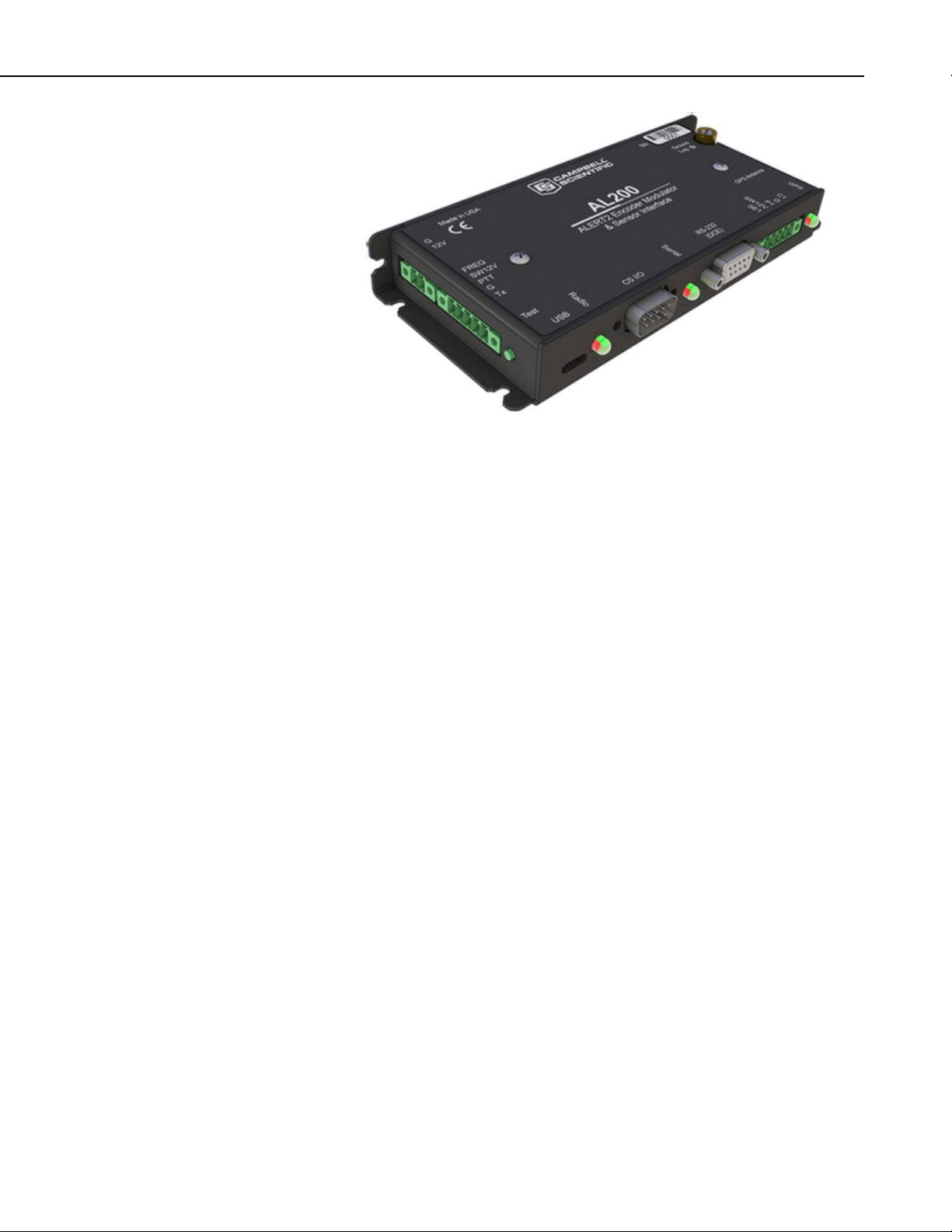
FIGURE 5-1. AL200
The AL200 includes a CS I/O port and an RS-232 port for serial
communications. A USB device port is used for configuring the AL200,
viewing real time sensor data, and diagnostics. An SMA female connector is
provided for connecting a GPS antenna, and a removable screw terminal allows
for the easy connection of an analog radio. Removable screw terminals are
also used for supplying power to the AL200 and connecting sensors. Lastly,
there is a copper ground lug for attaching an earth ground.
6. Specifications
Operating Temperature
Standard –40° to +60°C
Power
9-18 Vdc
Current Drain @ 12 Vdc
Idle: 1.5 mA
GPS Fix: 40 mA
Transmit: 35 mA (not including radio or attached sensors)
Reverse polarity protected
Removable screw terminal connector, 0.15” pitch
Weight
206 g (7.3oz)
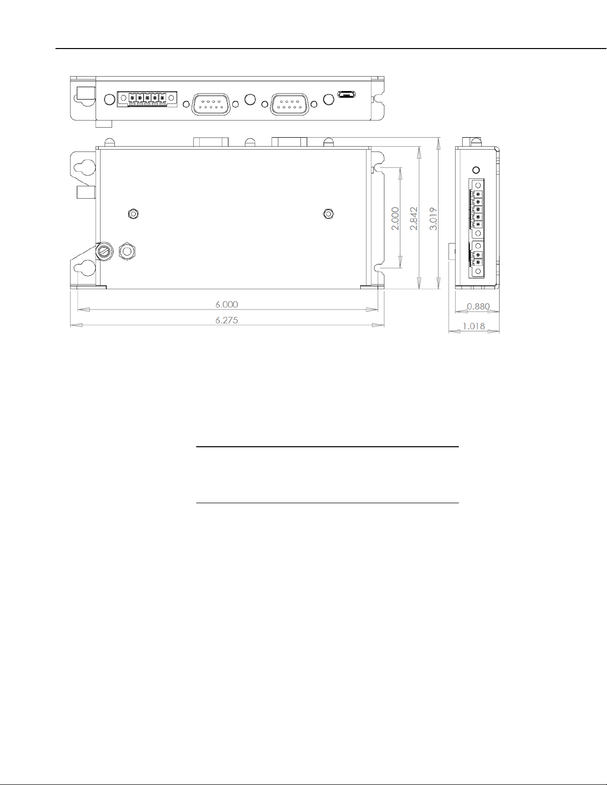
Dimensions
159.385 x 76.683 x 25.857 mm (6.275 x 3.019 x 1.018 in)
5
AL200 ALERT2 Encoder, Modulator, and Sensor Interface
NOTE
FIGURE 6-1. AL200 dimensions
Configuration
This device is designed to easily be configured through the graphical
interface, Device Configuration Utility. When used as a stand-alone
device, no programming is required.
The device driver for the AL200 must be installed on your
computer before you can connect to the AL200 via USB. See
Appendix E, AL200 USB Driver Installation Instructions, for
instructions on installing the device driver.
When used as a datalogger peripheral, the same Device Configuration
Utility software is used to configure the AL200. Additional steps will be
required to program the datalogger to interface with the AL200.
USB
Micro-B receptacle
Can power AL200 during configuration; not suitable for operational
current draws
Requires FTDI Virtual COM Port (VCP) driver installation
6
CS I/O Port
SDC 7, 8, 10, 11
ALERT2 or ALERT-concentration
AL200 is NOT powered over CS I/O
Multiplexed with integrated sensor I/O

AL200 ALERT2 Encoder, Modulator, and Sensor Interface
RS-232 Port
DCE
Configurable baud rates, parity, stop bits, and timeout
ElA/TIA-232 and V.28/V.24 Signaling
± 15kV ESD protection
Test Button
The test button located in the lower left hand corner of the AL200 serves
two functions. Pressing it for three to six seconds will trigger a test
transmission containing the latest data available to the AL200. Pressing
the button for longer than 6 seconds will cause the AL200 to generate a
test tone and sustain it for 5 seconds. If the AL200 has been configured as
a datalogger peripheral, only the test tone functionality is active.
Analog Radio Interface
Removable screw terminal connector, 0.15” pitch
Transmit only
Transmit Audio (Tx), 100 – 1000 mV peak-to-peak, software adjustable
Switched Voltage (SW12V), switched supply voltage, 1.8 A at +70°C
Sensor I/O
Removable screw terminal connector, 0.15” pitch
Switch closure (P1)
Internally pulled up to 5 V
16-bit counter
3.3 ms time constant for debounce
5 ms minimum closed time, 6 ms minimum open time
Single-ended analog (SE1)
16-bit Adc
0-5 Vdc
± 12 mV accuracy
80 µV resolution
50 dB rejection at 60 Hz
Software configurable as millivolt or milliamp input
Precision 100 Ω current sense resistor when configured for
milliamp input
Digital I/O (C1)
Software configurable as status (high/low) or SDI-12 input
Status Low 0 to 1.4 Vdc, High 3.5 to 5.0 Vdc
SDI-12 limited to 1 address, 1 value
Transient voltage surge (TVS) and gas discharge tube (GDT)
protected
7

AL200 ALERT2 Encoder, Modulator, and Sensor Interface
NOTE
Switched Voltage (SW12V)
Voltage supply switched on prior to operational sensor scan
Thermal fuse hold current = 900 mA @ 20°C, 630 mA @ 50°C,
450 mA @ 70°C
GPS
SMA Female
50 Ω input impedance
Active antenna design, 3.3 Vdc
25 dBm maximum input
Integrated SAW filtering and jam resistance
1 second time-to-fix during normal operation
35 second time-to-fix on power up or reboot
13 min for leap second, once per day auto
PPS ± 1 usec to full UTC second
Receive sensitivity –161 dBm
Timekeeping
GPS disciplined to ± 1 µS
Drift ± 170 ms per day with 40°C temperature change (w/o GPS sync)
7. Installation
7.1 Configuring the AL200
Compliance
RoHs
CE
IEC61000-4 ESD
The AL200 is configured via the USB port using the Device Configuration
Utility.
It is important to have an understanding of the network that the AL200 will be
used in. There are many settings that are used to configure when and how the
AL200 will report data in the time division multiple access (TDMA) scheme.
Incorrect settings can cause channel contention and may result in lost data.
The device driver for the AL200 must be installed on your
computer before you can connect to the AL200 via USB. See
Appendix E, AL200 USB Driver Installation Instructions, for
instructions on installing the device driver.
1. Connect the supplied USB cable between a USB port on your computer
and the USB port on the AL200. The AL200 will be powered over the
USB for configuration only. The AL200 will not turn on an attached radio
and transmit while powered over the USB port.
8
2. Open Device Configuration Utility.

3. Under Device Type, select AL200.
NOTE
4. Click the browse button next to Communication Port and select the port
associated with the AL200.
5. Click OK.
6. Click Connect.
7. Specify the settings on each tab as described below for the desired mode.
When a value is shown in parentheses next to a setting, it is the
default values that should work in most cases. Do not change
these values, unless you are certain a change is required.
7.1.1 Stand-alone Device
Main
• Set the Operation Mode to Sensor Input Enabled (CS I/O
Disabled), ALERT Concentration on RS-232.
AL200 ALERT2 Encoder, Modulator, and Sensor Interface
ComPort
These settings have no effect in stand-alone mode.
ALERT2
These settings will be unique to a particular station and to your network.
• Set the Station Source Address – This is a station ID number that
must be unique within the network. This is an integer between 0 and
65,501. A database of source addresses can be found at
www.alert2.org.
• Set the Frame Length – This is the total amount of time that all of the
stations in the network will report in. This is an integer with a
resolution of 500 ms between 500 and 43,200,000 (12 hours).
• Set the Slot Length – This is the maximum amount of time within the
frame that the station can report. It is an integer value between 500
and a maximum of the Frame Length.
• Set the Slot Offset – This is the amount of time into the frame that the
slot will occupy. For example, if your frame is 120,000 ms (2
minutes) and your slot offset is 60,000 ms, the slot time will begin 1
minute after the beginning of the frame.
• Set the Hop Limit – (None) – This is the maximum number of times a
remote transmission can be retransmitted by repeaters.
• Set the Path Service Enabled – (No) – When enabled, each device
that repeats a remote transmission will add its source address to the
9

AL200 ALERT2 Encoder, Modulator, and Sensor Interface
packet. This makes it possible to trace the path that a packet took
from its beginning to its destination.
Radio Settings
The default radio settings have been chosen to work well with Campbell
Scientific’s RF320 series (Ritron DTX-L series) radios. If using a different
type of radio, consult the manufacturer and apply the changes to the following
settings.
• Set the Radio Power Up Mode – (On Only With Data to TX) – This
determines when the radio will be powered on.
• Set the Radio Warm Up – (750) – This is the amount of time, in
milliseconds, that power will be applied to the external radio prior to
data transmission.
• Set the Carrier Only Time – (10) – This is the amount of time, in
milliseconds, that radio will be fed an unmodulated carrier.
• Set the AGC Time – (25) – This is the amount of time, in
milliseconds, that the radio will be fed a tone-modulated carrier.
• Set the Tail Time – (5) – This is the amount of time, in milliseconds,
an unmodulated carrier will be transmitted following data
transmission.
• Set the Modulation Voltage – (390) – This is the peak-to-peak
voltage level of the modulated signal that will be fed to the radio.
Value is expressed in millivolts.
• Set the Modulation Polarity – (Normal) – This is the polarity of the
modulated signal fed to the radio.
GPS Settings
• Last GPS Fix – This is the data and time of the last successful GPS
fix obtained by the AL200.
• Set the GPS Power On Interval – (30) – This is how often the GPS
receiver will be powered on and an attempt to get a GPS fix will be
made. Value is expressed in minutes.
• Set the GPS On Max – (5) – This is the maximum amount of time, in
minutes, that the GPS receiver will be powered on without a GPS fix
being obtained.
Sensor Input Settings
10
• Set the Self Report Interval – (43,200,000 (12 hours)) – This is how
often the AL200 will transmit non-event triggered data. Value is
expressed in seconds.

AL200 ALERT2 Encoder, Modulator, and Sensor Interface
• Set the Sensor Scan Interval – This is how often the AL200 will
power up and measure attached and enabled sensors. Value is
expressed in seconds.
• Set the SW12 Warm Up Time – This is the amount of time in
seconds that the AL200 will wait after powering up attached sensors
before making a measurement.
• Set the P1 Mode – Enable or disable the pulse count channel
depending on whether or not it is being used.
• Set the SE1 Mode – Set to Millivolt if using a sensor that has a single
ended voltage output. Set to Milliamp if sensor has a single ended
current output or 4-20 mA loop output.
• Set the SE1 ALERT2 Sensor ID – This is the sensor ID of the sensor
connected to the SE1 channel. See Appendix G, List of
Recommended Sensor IDs, for a list of recommended sensor ID
values.
• Set the SE1 Multiplier – This is a sensor specific value that along
with the SE1 Offset will be used to convert the analog output of a
sensor to an engineering unit. See Appendix H, Calculating
Multipliers and Offsets, for how to calculate multipliers and offsets.
• Set the SE1 Offset – This is a sensor specific value that along with the
SE1 Multiplier will be used to convert the analog output of a sensor to
an engineering unit. See Appendix H, Calculating Multipliers and
Offsets, for how to calculate multipliers and offsets.
• Set the SE1 Tx Change – This is the threshold which a calculated
value for the SE1 measurement must exceed in order to trigger a data
transmission.
• Set the C1 Mode – Set to Status to configure C1 to read a dry contact
(commonly a float switch). Set to SDI-12 to configure for use with an
SDI-12 type sensor.
• Set the C1 ALERT2 Sensor ID – This is the sensor ID of the sensor
connected to the C1 channel. See Appendix G, List of Recommended
Sensor IDs, for a list of recommended sensor ID values.
• Set the SDI-12 Command – This is the measurement command that
will be sent to the attached SDI-12 sensor. The format is xM!, where
x is the SDI-12 address.
• Set the SDI-12 Value to Send – If the attached SDI-12 sensor returns
more than one value, select which value will be used.
• Set the SDI-12 Multiplier – (1) – This is a sensor specific value that
along with the SDI-12 Offset will be used to convert the analog output
of a sensor to an engineering unit. See Appendix H, Calculating
Multipliers and Offsets, for how to calculate multipliers and offsets.
(Note that most SDI-12 sensors do not require a multiplier or offset
except for unit conversion.)
11

AL200 ALERT2 Encoder, Modulator, and Sensor Interface
• Set the SDI-12 Offset – (0) – This is a sensor specific value that along
with the SE1 Multiplier will be used to convert the analog output of a
sensor to an engineering unit. See Appendix H, Calculating
Multipliers and Offsets, for how to calculate multipliers and offsets.
(Note that most SDI-12 sensors do not require a multiplier or offset
except to convert units of measure.)
• Set the SDI-12 Tx Change – This is the threshold which a calculated
value for the SDI-12 measurement must exceed in order to trigger a
data transmission.
Sensor Data Monitoring
• Set the Configuration Sensor Scan Interval – This is the interval on
which sensors will be read only while you are connected to the AL200
with the Device Configuration Utility software.
After configuring the AL200 settings, click the Apply button at the bottom of
the screen to send the changes to the device. It is a good idea to save the
configuration file for later reference.
7.1.2 Datalogger Peripheral
Main
• Set the Operation Mode to either ALERT2 on CS I/O, ALERT
Concentration on RS-232 or ALERT Concentration on CS I/O,
ALERT2 on RS-232 depending on what type of device the AL200
will be connected to.
ComPort
• If the AL200 is connected to a Campbell Scientific datalogger, select
the appropriate SDC address. When using the CS I/O port, it is not
necessary to configure the RS-232 related settings.
• If the AL200 is connected to an RS-232 device, configure the RS-232
Baud Rate, RS-232 Parity, and RS-232 Stop Bits to match the
device.
ALERT2
These settings will be unique to a particular station and to your network.
• Set the Station Source Address – This is a station ID number that
must be unique within the network. This is an integer between 0 and
65,501. A database of source addresses can be found at
www.alert2.org.
12
• Set the Frame Length – This is the total amount of time that all of the
stations in the network will report in. This is an integer with a
resolution of 500 ms between 500 and 43,200,000 (12 hours).

AL200 ALERT2 Encoder, Modulator, and Sensor Interface
• Set the Slot Length – This is the maximum amount of time within the
frame that the station can report during. It is an integer value between
500 and a maximum of the Frame Length.
• Set the Slot Offset – This is the amount of time into the frame that the
slot will occupy. For example, if your frame is 120,000 ms (2
minutes) and your slot offset is 60,000 ms, the slot time will begin 1
minute after the beginning of the frame.
• Set the Hop Limit – (None) – This is the maximum number of times a
remote transmission can be retransmitted by repeaters.
• Set the Path Service Enabled – (No) – When enabled each device
that repeats a remote transmission will add its source address to the
packet. This makes it possible to trace the path that a packet took
from its beginning to its destination.
Radio Settings
The default radio settings have been chosen to work well with Campbell
Scientific’s RF320 series (Ritron DTX-L series) radios. If using a different
type of radio, consult the manufacturer and apply the changes to the following
settings.
• Set the Radio Power Up Mode – (On Only With Data to TX) – This
determines when the radio will be powered on.
• Set the Radio Warm Up – (750) – This is the amount of time, in
milliseconds, that power will be applied to the external radio prior to
data transmission.
• Set the Carrier Only Time – (10) – This is the amount of time, in
milliseconds, that radio will be fed an unmodulated carrier.
• Set the AGC Time – (25) – This is the amount of time, in
milliseconds, that the radio will be fed a tone-modulated carrier.
• Set the Tail Time – (5) – This is the amount of time, in milliseconds,
an unmodulated carrier will be transmitted following data
transmission.
• Set the Modulation Voltage – (390) – This is the peak-to-peak
voltage level of the modulated signal that will be fed to the radio.
Value is expressed in millivolts.
• Set the Modulation Polarity – (Normal) – This is the polarity of the
modulated signal fed to the radio.
GPS Settings
• Last GPS Fix – This is the data and time of the last successful GPS
fix obtained by the AL200.
13

AL200 ALERT2 Encoder, Modulator, and Sensor Interface
• Set the GPS Power On Interval – (30) – This is how often the GPS
receiver will be powered on and an attempt to get a GPS fix will be
made. Value is expressed in minutes.
• Set the GPS On Max – (5) – This is the maximum amount of time, in
minutes, that the GPS receiver will be powered on without a GPS fix
being obtained.
Sensor Input Settings
These settings have no effect in datalogger peripheral mode.
Sensor Data Monitoring
These values are not updated when the AL200 is configured as a datalogger
peripheral.
After configuring the AL200 settings, click the Apply button at the bottom of
the screen to send the changes to the device. It is a good idea to save the
configuration file for later reference.
7.2 Mounting in an Enclosure
7.3 Grounding
7.4 Wiring
8. Operation
When used in outdoor applications, the AL200 should be installed in a
desiccated, weatherproof enclosure. The AL200 can either be flat- or edgemounted to a panel using the supplied plastic grommets and 6-32 screws.
The ground lug should be connected to a good earth ground using 12 AWG
stranded wire. This will help protect the AL200 from electrical surges and
provide a good reference for analog measurements.
Connect the transmit, power, and ground lines (Push to Talk and Frequency
Select lines are optional) from your analog radio to the SW12V, Tx and G
terminals of the radio connector. The AL200 should be mounted as close as
possible to the radio in order to avoid long cable runs between the two devices.
Connect the sensor leads to the appropriate sensor inputs. Depending on site
conditions, additional surge protection for the sensor cables may be required.
If using the AL200 as a datalogger peripheral, connect either the CS I/O or RS232 port to the datalogger using the supplied SC12 cable.
14
The AL200 uses the ALERT2 protocol as developed by the ALERT2
Technical Working Group (TWG) and is designed for use as an ALERT2
transmitter or ALERT to ALERT2 concentrator and repeater. For more
information on the ALERT2 protocol, visit the National Hydrologic Warning
Council’s website: www.hydrologicwarning.org.

AL200 ALERT2 Encoder, Modulator, and Sensor Interface
Under normal operation, the AL200 will obtain a GPS fix and measure sensors
based on its configuration. When the sensors are measured and an event
threshold has been exceeded, the AL200 will wait until its designated time slot
and then power up the radio and transmit the data to a repeater or base receiver.
• Concentrated ALERT data is retransmitted using the ALERT
concentration protocol.
• Event-driven rainfall data is transmitted as a tipping bucket rain gauge
report with a sensor ID of zero (0).
• Other event-driven sensor data is transmitted as a general sensor
report. If events for multiple sensors are detected in the same frame,
then multiple general sensors reports will be transmitted.
• A scheduled self-report is transmitted as a multi-sensor report.
If a GPS fix cannot be obtained and the AL200’s internal clock cannot be
disciplined, the device will transmit data during random slot times throughout
the frame interval in an attempt to not continuously interfere with adjacent time
slots.
9. Maintenance
When connected to the AL200 with the Device Configuration Utility, the
AL200 will power up and measure the attached sensors on the Configuration
Sensor Scan Interval located on the Sensor Data Monitoring tab, but
transmissions will be suppressed.
It is a good idea to periodically check the sensor inputs against known values to
ensure that the device is still within the specified accuracy ranges. Connecting
to the AL200 with a USB cable will force the AL200 to measure the attached
sensors on the Configuration Sensor Scan Interval. This will allow the user
to quickly see how sensors respond to changes. Upon disconnecting from the
device, the AL200 will resume its Sensor Scan Interval.
Pressing the test button for three to six seconds will trigger a test transmission
containing the latest data available to the AL200. Pressing the button for
longer than six seconds will cause the AL200 to generate a test tone and sustain
it for five seconds. This test tone can be used to check the forward and
reflected power of the radio.
Consult your sensor and radio manufacturer’s manuals for recommended
maintenance of these devices.
15

AL200 ALERT2 Encoder, Modulator, and Sensor Interface
10. Troubleshooting
Problem Possible Causes
The AL200 will not transmit eventtriggered data.
The Test Button is not initiating a
data transmission.
The AL200 is reporting incorrect
values.
The radio LED is always red. • The AL200 has been configured to
• The AL200 is currently connected
to Device Configuration Utility and
data transmissions are being
suppressed.
• The event threshold is not properly
set.
• The AL200 is not currently
measuring a level that exceeds the
event threshold.
• The AL200 has not obtained an
initial GPS fix.
• The AL200 has not obtained an
initial GPS fix.
• The AL200 has been configured as
a datalogger peripheral and the test
button functionality has been
disabled.
• The applied multipliers and offsets
are not correct.
• There is an issue with the attached
sensor or sensor wiring.
keep the radio always on.
11. Repair
The GPS LED is on longer than the
maximum allowed on time.
The AL200 is designed to give years of trouble-free service with reasonable
care. However, if factory repair is needed, first contact a Campbell Scientific
application engineer to obtain an RMA (Return Materials Authorization)
number. An RMA number and product-safety documents are required prior to
any repair shipments being accepted at Campbell Scientific. See the
Assistance statement at the beginning of this manual for more information.
• The GPS module is attempting to
obtain leap second information and
may be on for up to 13 minutes.
16

Appendix A. Glossary
ALERT
Automated Local Evaluation in Real Time. A communication protocol
developed in the early 1970’s for the efficient reporting of real-time rainfall
data over radio telemetry networks.
ALERT2
Successor of the ALERT communication protocol. A layered protocol suite
designed for the primary purpose of real-time and coordinated communication
of data over a radio telemetry network.
IND
Intelligent Network Device. A device that implements the AirLink and MANT
protocols for the transmission, repeating, or receipt of ALERT2 data.
MANT
ALERT2 Network and Transport layer providing the required services to
transport application and network control data.
PDU
Protocol Data Unit. Data payload with control header used for exchange
between protocol layers. Sometimes generalized as “packet”.
SDC
Synchronous Device Communications. A Campbell Scientific addressable,
synchronous communications protocol. The protocol allows multiple
peripherals to be connected to the same communication bus as long as each
peripheral has a unique SDC address.
A-1

Appendix A. Glossary
A-2

TABLE B-1. CS I/O Pin Description
TABLE B-2. RS-232 Pin Description
1
N/C
3
RXD
5
SIGNAL GND
7
CTS
9
N/C
Appendix B. Cables and Connector Pin Descriptions
B.1 CS I/O
CS I/O is an interface unique to Campbell Scientific products. CS I/O uses
TTL signaling. CS I/O devices are connected using a 9-pin, straight-through,
male to female cable with all 9 pins connected. Use of the supplied SC12 cable
(pn 16675) is recommended.
Pin Datalogger Function, DB9 Female AL200 Function, DB9 Male
1 5 VDC N/C
2 SIGNAL GND SIGNAL GND
3 RING RING
4 RXD TXD
5 ME ME
6 SDE SDE
7 CLK/HS CLK/HS
8 12 VDC N/C
9 TXD RXD
B.2 RS-232
RS-232 is used for asynchronous serial communication. It is a standard
EIA/TIA-232 DB9 socket female DCE interface. A DB9 male to male null
modem cable (pn 18663) is used to connect the AL200 to a Campbell
Scientific datalogger’s RS-232 port.
Pin AL200 Function, DCE, DB9 Female
2 TXD
4 N/C
6 N/C
8 RTS
B-1

Appendix B. Cables and Connector Pin Descriptions
TABLE B-3. USB Pin Description
TABLE B-4. Power Input Pin Description
B.3 USB
The USB interface is a standard Micro-B configuration. A USB A to Micro-B
cable is supplied (pn 27555). Connection to a PC requires installation of the
FTDI Virtual COM Port (VCP) device driver.
Pin Function
1 VBUS, 5 Vdc
2 Data -
3 Data +
4 Not used, Grounded Internally
5 GND
B.4 Power
Input power is supplied via a 2-pin screw terminal. A mating connector is
supplied (pn 7843).
Pin Function
G Supply Ground
12V Supply Voltage
B.5 Analog Radio Interface
The analog radio interface is a 5-pin screw terminal. A mating connector is
supplied (pn 28750).
B-2

TABLE B-5. Radio Interface Pin Description
Pin Function
TABLE B-6. Sensor I/O Pin Description
TABLE B-7. GPS Input Pin Description
Freq. Select Frequency Select. Accommodate frequency selection during
SW12V Switchable radio power supply
PTT Push-to-talk. Grounded during transmission.
G Ground
TX Transmit audio output
B.6 Sensor I/O Interface
The sensor I/O interface is a 5-pin screw terminal. A mating connector is
supplied (pn 28750).
Appendix B. Cables and Connector Pin Descriptions
operation by grounding selected pin on radio interface.
B.7 GPS Input
Pin Function
SE1 Analog voltage / current input
SW12V Switchable sensor power supply
P1 Switch closure input. Internally tied high to 5V.
G Ground
C1 Digital I/O for high/low status or SDI-12
The GPS input is a threaded SMA female connector.
Pin Function
Center Conductor Socket RF Input, biased by 3.3 V for use with active
antennas
Shield RF ground
B-3

Appendix B. Cables and Connector Pin Descriptions
B-4

TABLE C-1. GPS LED State Descriptions
TABLE C-2. Serial LED State Descriptions
TABLE C-3. Radio LED State Descriptions
Appendix C. LED Indicators
The GPS LED is next to the GPS antenna connection. It can be used for
monitoring GPS power up and acquisition of a good satellite lock / fix.
State Description
Off GPS module in “hibernate state”
Green GPS lock acquired (will only flash momentarily before turning off)
Red GPS module on, No GPS Lock (or downloading almanac/leap
second information)
The Serial LED is located between the RS-232 and CS I/O interfaces. It can be
used for monitoring communication events on those ports.
State Description
Off Neither interface is currently transferring data
Green RS-232 activity, Internal U0 activity
Red CS I/O activity, Internal U1 activity
The Radio LED is located between the CS I/O and USB interfaces. It can be
used for monitoring the power and communication state of the radio interface.
State Description
Off Radio interface not currently in use
Green PTT applied, Transmitting
Red Power applied to radio, SW12V high
*When the radio is both powered on and transmitting, the red and green
LEDs will appear orange.
Under normal operation, the LED sequence should be as follows from
powering up the device through a data transmission:
a. GPS LED is red immediately after power, then flashes green
indicating that the AL200 has a GPS fix.
C-1

Appendix C. LED Indicators
b. The GPS light remains red for up 13 minutes as the AL200 downloads
leap second information from the satellite.
c. The Serial LED flashes green or red indicating that the AL200 has
been sent data from a datalogger, or data is being internally
transferred from the sensor inputs to memory.
d. The Radio LED is red briefly while the radio is powered up and
allowed to warm up. If the radio is set to always on, this LED will
constantly be red.
e. The Radio LED flashes orange (actually green and red lights, but is
orange in appearance) indicating that the AL200 is transmitting data.
C-2

Appendix D. AL200 Settings
Operation Mode The AL200 supports ALERT2 and ALERT-concentration processing. Each process
can service one physical connection on the AL200 at a time. Those connections are
the CS I/O, RS-232, and direct-sensor inputs. The CS I/O port and sensor inputs are
multiplexed, so their use is mutually exclusive.
• ALERT2 on CS I/O, ALERT Concentration on RS-232
In this mode, the AL200 will accept ALERT2 on the CS I/O port and
ALERT packets on the RS-232 port.
• Sensor Input Enabled (CS I/O Disabled), ALERT Concentration on
RS-232
In this mode, the AL200 will measure attached sensors and receive serial
ALERT packets on the RS-232 port.
• ALERT Concentration on CS I/O, ALERT2 on RS-232
In this mode, the AL200 will accept ALERT on the CS I/O port and
ALERT2 on the RS-232 port.
OS Version The version of the operating system currently running on this device. Updates can be
found on Campbell Scientific’s website, www.campbellsci.com/downloads.
CS I/O SDC Address Synchronous Device for Communication (SDC) address that this device should use
while communicating over CS I/O. Communication speed (bit rate) is controlled by
the datalogger.
RS-232 Baud Rate The baud rate used for communication over RS-232.
RS-232 Parity Parity bit usage during communication over RS-232.
RS-232 Stop Bits The number of stop bits sent after each character during communication over RS-
232.
Time To Next Slot Time (seconds) until the next transmission slot.
Station Source Address ALERT2 station source address. Each station in an ALERT2 network should have a
unique source address.
Destination Address The source address of device that packets are directed to.
Add Destination Address Controls if Destination Address will be added to the packet header. A setting of No
will disable the Destination Address settings control.
Frame Length The total amount of time that all of the stations in the network will report within.
The value is expressed in milliseconds with a resolution of 500 ms. It is an integer
between 500 and 43,200,000 (12 hours). The value must be evenly divisible into 12
hours, that is (43200000 / Frame Length = Whole Number) or (43200000 MOD
Frame Length = 0).
Slot Length The maximum amount of time this device can transmit within a single frame. The
value is expressed in milliseconds with a resolution of 500 ms. It is an integer value
between 500 and a maximum of the Frame Length.
Slot Offset The offset, from the beginning of the frame, for the transmission slot. The value is
expressed in milliseconds with a resolution of 500 ms. The value cannot exceed
(Frame Length - 500 ms).
D-1

Appendix D. AL200 Settings
Hop Limit The maximum number of times a packet, originating from this device, will be
repeated (hop) before being discarded. None (7) disables the limiting of hops.
Example: if this station requires 1 repeater hop to reach the base station receiver, the
hop limit should be set to a minimum of 1.
Path Service Enabled Request that each device that forwards data originating from this station add its
source address to the packet header. Enabling this option allows a receiver to know
the path that the packet took through the network.
Radio Power Up Mode The setting controls when the attached radio is powered up. The radio can be
powered up every frame, continuously, or only when data is available for
transmission. For maximum power savings, set to On Only With Data to Tx. The
radio will only power up if the AL200 has data to be transmitted. For maximum
responsiveness, set to On Every Frame or On Continuously. If On Every Frame,
the radio will be turned on for a minimum of Radio Warm Up milliseconds every
frame.
Radio Warm Up The amount of time power should be applied to the radio prior to the start of the
transmission slot. Power will be applied according to the Radio Power Up Mode.
The value is expressed in milliseconds with a resolution of 10 ms.
Carrier Only Time Amount of unmodulated carrier used in Airlink preamble. The value is expressed in
milliseconds.
AGC Time Amount of tone-modulated carrier used in Airlink preamble. The value is expressed
in milliseconds.
Tail Time Amount of unmodulated carrier to follow transmitted frame. The value is expressed
in milliseconds.
Modulation Voltage This setting controls the modulation voltage. The value is expressed in millivolts,
peak-to-peak. Settings do not take effect until applied.
Modulation Polarity Depending on the radio used the audio AirLink modulation signal may need to be
inverted. For Midland and Ritron radios, set this to Normal.
Last GPS Fix The last time that the device successfully acquired a GPS fix. The time is shown in
UTC. Remember that you may need to correct for your time zone offset when trying
to understand this value in context of the local time.
GPS Power On Interval Time between GPS fix attempts. The value is expressed in minutes.
GPS On Max The maximum time the GPS will remain on while trying to obtain a fix. The value is
expressed in minutes.
Self Report Interval Controls the frequency at which sensor data should be reported, without being
triggered by an event. Value is expressed in seconds.
Sensor Scan Interval Controls the interval at which sensors, with the exception of P1, will be read during
normal operation. Value is expressed in seconds.
SW12 Warm Up Time Controls the amount of time SW12V should be on before reading sensor inputs, with
the exception of P1. A setting of –1 means SW12V will be left on continuously. A
setting of 0 means SW12V will not be enabled before measurement. Value is
expressed in seconds.
P1 Mode Enables the P1 terminal input. The P1 input is most commonly used for measuring
switch closures, like those commonly produced by a tipping bucket rain gage. An
ALERT2 sensor ID of 0 will be used for tipping bucket and general sensor reports for
this input.
D-2

Appendix D. AL200 Settings
For example, if the sensor returned 4 values, and the 3rd value needs to
SE1 Mode Sets the operation mode for the SE1 terminal input. SE1 is used for measuring
millivolt or milliamp input signals, like those commonly produced by a pressure
transducing level sensor.
SE1 ALERT2 Sensor ID The ALERT2 sensor ID that will be used to identify a SE1 general sensor report.
The ID cannot be set to 0 or 8. 0 is reserved for reporting P1 input. 8 is reserved for
reporting battery.
SE1 Multiplier Multiplier to apply to SE1 measurement before evaluation and transmission.
Example: Water Level = SE1 measurement • SE1 Multiplier + SE1 Offset.
SE1 Offset Offset to apply to SE1 measurement before evaluation and transmission. Example:
Water Level = SE1 measurement • SE1 Multiplier + SE1 Offset.
SE1 Tx Change Amount of change in reading required to trigger Tx of reading. Reading = SE1
measurement • SE1 Multiplier + SE1 Offset.
C1 Mode Sets the operation mode for the C1 terminal input. C1 is used for measuring status
(high/low) or SDI-12 inputs, like those produced by a float switch or pressure
transducing level sensor, respectively.
C1 ALERT2 Sensor ID The ALERT2 sensor ID that will be used to identify a C1 general sensor report. The
ID cannot be set to 0 or 8. 0 is reserved for reporting P1 input. 8 is reserved for
reporting battery.
SDI-12 Command SDI-12 command to be sent to the attached sensor.
SDI-12 Value to Send Selects which value returned by the SDI-12 sensor to use for evaluation and
transmission.
be used, this setting should be 3.
SDI-12 Multiplier Multiplier to apply to the SDI-12 measurement before evaluation. Example: Water
Level = SDI-12 measurement • SDI-12 Multiplier + SDI-12 Offset.
SDI-12 Offset Offset to apply to the SDI-12 measurement before evaluation. Example: Water Level
= SDI-12 measurement • SDI-12 Multiplier + SDI-12 Offset.
SDI-12 Tx Change Amount of change in the reading required to trigger Tx of reading. Reading = SDI-
12 measurement • SDI-12 Multiplier + SDI-12 Offset.
Configuration Sensor
Scan Interval
Controls the interval at which sensors, with the exception of P1, will be read while
connected with Device Configuration Utility. Value is expressed in seconds. This
setting does not take effect until settings are applied.
Battery Battery / supply voltage (volts). While connected via Device Configuration Utility,
the battery voltage will be measured every Configuration Sensor Scan Interval.
The measured value will be queried and displayed here at a regular refresh interval.
P1 Total If the P1 input is enabled, the total number of counts since the device was last
powered up or reset will be displayed here. The measured value will be queried and
displayed here at a regular refresh interval.
SE1 Raw Reading If SE1 is enabled, the SE1 reading without SE1 Multiplier and SE1 Offset applied.
While connected via Device Configuration Utility, SE1 will be measured every
Configuration Sensor Scan Interval. The measured value will be queried and
displayed here at a regular refresh interval.
SE1 Scaled Reading If SE1 is enabled, the SE1 reading, with SE1 Multiplier and SE1 Offset applied.
While connected via Device Configuration Utility, SE1 will be measured every
Configuration Sensor Scan Interval. The measured value will be queried and
displayed here at a regular refresh interval.
D-3

Appendix D. AL200 Settings
SE1 Transmitted Last three transmitted readings for SE1 (T0, T1, T2). The list will be queried and
displayed here at a regular refresh interval. While connected via Device
Configuration Utility, automated reporting/transmission is disabled. Press and hold
the test button for 3 to 5 seconds to force a transmission while connected.
C1 Raw Reading If C1 input is enabled, this will be either a) the control port state or b) the value for
SDI-12 without SDI-12 Multiplier and SDI-12 Offset applied, during the last sensor
scan. While connected via Device Configuration Utility, C1 will be measured every
Configuration Sensor Scan Interval. The measured value will be queried and
displayed here at a regular refresh interval.
C1 Scaled Reading If C1 input is enabled, this will be either a) the control port state or b) the value for
SDI-12 with SDI-12 Multiplier and SDI-12 Offset applied, during the last sensor
scan. While connected via Device Configuration Utility, C1 will be measured every
Configuration Sensor Scan Interval. The measured value will be queried and
displayed here at a regular refresh interval.
C1 Transmitted If C1 input is enabled, this will be either a) the control port state or b) the value for
SDI-12 for the last three transmitted readings of C1 (T0, T1, T2). The list will be
queried and displayed here at a regular refresh interval. While connected via Device
Configuration Utility, automated reporting/transmission is disabled. Press and hold
the test button for 3 to 5 seconds to force a transmission while connected.
D-4

Appendix E. AL200 USB Driver Installation Instructions
When plugging the AL200 into your Windows XP or Vista PC for the first
time, it may be necessary to install the FTDI Virtual COM Port (VCP) driver.
This is not required when using Windows 7 or 8.
Visit www.ftdichip.com/Drivers/VCP and select the appropriate file based on
your computer’s operating system. Download the zip file to your PC and
extract the files to a directory of your choosing. Select and open the executable
file and proceed through the install wizard. After the drivers finish installing,
you should see a confirmation screen indicating that the drivers were installed
or updated successfully. You will then need to restart your computer to apply
the changes.
E-1

Appendix E. AL200 USB Driver Installation Instructions
E-2

Appendix F. Updating the Operating System of the AL200
Whenever a new operating system is released for the AL200, it will be
available from our website, www.campbellsci.com/downloads.
Follow these steps to send the new OS to the AL200:
1. Connect a USB cable between one of your computer’s USB ports and the
USB port on the AL200.
2. Open DevConfig.
3. Select the AL200 under Device Type.
4. Select the appropriate Communication Port.
5. Go to the Send OS tab.
6. Press the Start button.
7. In the resulting dialog box, select the file that should be sent to the device
as an operating system (this file should have a .hex extension) and press
the OK button.
8. The operating system will be sent to the AL200.
9. Do not remove power while an OS download is in process.
F-1

Appendix F. Updating the Operating System of the AL200
F-2

TABLE G-1. Recommended Sensor IDs
Appendix G. List of Recommended Sensor IDs
ID Sensor Type
0 Rain
1 Air Temperature
2 Relative Humidity
3 Barometric Pressure
4 Wind Speed
5 Wind Direction
6 Peak Wind Speed
7 Stage
8 Battery Voltage
*As recommended in the ALERT2 Application Layer Protocol Specification
document, Version 1.2.
G-1

Appendix G. List of Recommend Sensor IDs
G-2

1X2
X
1Y
2Y
Multiplier
−
−
=
mVper psi 0060.0
)7.4974(30)3.
124987(
030
Multiplier =
=
−
−
=
( )
mVper psi 074.03.12•0060.00Offset −=−=
Appendix H. Calculating Multipliers and Offsets
Unlike ALERT which could only represent measurement values between 0 and
2047, ALERT2 has the ability to represent a much larger range of floating
point numbers. It is no longer necessary to scale a reading to a unit-less
number less than 2047. Instead, with ALERT2, you can transmit values in
engineering units with a high degree of resolution. The simplified example
below demonstrates how to calculate the multiplier and offset that are needed
to convert a pressure transducer’s output, 0-5 volts, to feet of water.
For this example we will use a pressure transducer that has a 0 to 30 psi range
and a 0 to 5 volts output. From the manufacturer supplied calibration report it
is known that the sensor outputs 0.0123 volts at 0 psi and 4.987 volts at 30 psi
(12.3 and 4987 millivolts respectively).
The relationship between the sensor’s output in millivolts and pressure is
defined by the equation of a line (assuming linearity), Y = mX + b, where Y is
pressure, m is the calculated multiplier, X is the sensor’s output in millivolts,
and b is the calculated offset.
Y = mX + b
OR
Pressure = Multiplier • Sensor Output + Offset
The multiplier is determined by dividing the sensor’s measurement ranges by
the sensor’s range of output. For this example the multiplier will be:
OR
The offset is determined by entering the multiplier into the pressure equation
and solving for the offset using a known pressure and sensor output.
Offset = Pressure – (Multiplier • Sensor Output)
OR
H-1

Appendix H. Calculating Multipliers and Offsets
Now, we can calculate pressure based on the reading we get from the sensor.
For example, you measure the sensor’s output as 2543.210 mV. Pressure
would be determined by:
Pressure = (0.0060 • 2543.210) + (–0.074) = 15.263 psi
To determine water depth, simply multiply the pressure value by the
appropriate conversion factor.
For fresh water this is:
1 psi = 2.308 ft.
For salt water this is:
1 psi = 2.250 ft.
For the above example (assuming fresh water):
Depth of Water = Pressure • 2.308
Depth of Water = 15.263 • 2.308 = 35.226 ft.
These calculations can easily be performed using many spreadsheet programs
by plotting the sensor’s measurement range versus the sensor’s output range.
The equation of the trendline contains the multiplier and offset.
H-2


Campbell Scientific Companies
Campbell Scientific, Inc. (CSI)
815 West 1800 North
Logan, Utah 84321
UNITED STATES
www.campbellsci.com • info@campbellsci.com
Campbell Scientific Africa Pty. Ltd. (CSAf)
PO Box 2450
Somerset West 7129
SOUTH AFRICA
www.csafrica.co.za • cleroux@csafrica.co.za
Campbell Scientific Australia Pty. Ltd. (CSA)
PO Box 8108
Garbutt Post Shop QLD 4814
AUSTRALIA
www.campbellsci.com.au • info@campbellsci.com.au
Campbell Scientific (Beijing) Co., Ltd.
8B16, Floor 8 Tower B, Hanwei Plaza
7 Guanghua Road
Chaoyang, Beijing 100004
P.R. CHINA
www.campbellsci.com • info@campbellsci.com.cn
Campbell Scientific do Brasil Ltda. (CSB)
Rua Apinagés, nbr. 2018 ─ Perdizes
CEP: 01258-00 ─ São Paulo ─ SP
BRASIL
www.campbellsci.com.br • vendas@campbellsci.com.br
Campbell Scientific Canada Corp. (CSC)
14532 – 131 Avenue NW
Edmonton AB T5L 4X4
CANADA
www.campbellsci.ca • dataloggers@campbellsci.ca
Please visit www.campbellsci.com to obtain contact information for your local US or international representative.
Campbell Scientific Centro Caribe S.A. (CSCC)
300 N Cementerio, Edificio Breller
Santo Domingo, Heredia 40305
COSTA RICA
www.campbellsci.cc • info@campbellsci.cc
Campbell Scientific Ltd. (CSL)
Campbell Park
80 Hathern Road
Shepshed, Loughborough LE12 9GX
UNITED KINGDOM
www.campbellsci.co.uk • sales@campbellsci.co.uk
Campbell Scientific Ltd. (CSL France)
3 Avenue de la Division Leclerc
92160 ANTONY
FRANCE
www.campbellsci.fr • info@campbellsci.fr
Campbell Scientific Ltd. (CSL Germany)
Fahrenheitstraße 13
28359 Bremen
GERMANY
www.campbellsci.de • info@campbellsci.de
Campbell Scientific Spain, S. L. (CSL Spain)
Avda. Pompeu Fabra 7-9, local 1
08024 Barcelona
SPAIN
www.campbellsci.es • info@campbellsci.es
 Loading...