

Page 1

2
SSDDII--112
Probe Interface Manual Version 3.4
(For firmware revision 1.2.3 or above)
Page 2

All rights reserved. No part of this document may be reproduced, transcribed, translated into any language or
transmitted in any form electronic or mechanical for any purpose whatsoever without the prior written consent
of Sentek Pty Ltd. All intellectual and property rights remain with Sentek Pty Ltd.
All information presented is subject to change without notice.
2003 Sentek Pty Ltd
EnviroSMART, EasyAG and TriSCAN are registered trademarks of Sentek Pty Ltd.
Details of SDI-12 specifications can be obtained from the SDI-12 Support Group, Technical Committee, at
www.sdi-12.org.
Sentek Pty Ltd
A.C.N. 007 916 672
77 Magill Road
Stepney, South Australia 5069
Phone: +61 8 8366 1900
Facsimile: +61 8 8362 8400
Internet: www.sentek.com.au
Email: sentek@sentek.com.au
Page 3

EnviroSMART® and EasyAG® - Statements of Compliance
FCC note of compliance and statement of liability
Electro-Magnetic Compliance
This equipment has been tested and found to comply with the limits for a Class B digital device,
pursuant to part 15 of the FCC rules. These limits are designed to provide reasonable protection against
harmful interference in a residential installation. This equipment generates, uses and can radiate radio
frequency energy and, if not installed and used in accordance with the instructions, may cause harmful
interference to radio communications. However, there is no guarantee that interference will not occur
in a particular installation. If this equipment does cause harmful interference to radio or television
reception, which can be determined by turning the equipment off and on, the user is encouraged to try
to correct the interference by one or more of the following measures:
• Reorientation or relocation of the receiving antenna.
• Connection of the equipment into an outlet on a circuit different from that to which the
receiver is connected.
• Consultation with the dealer or an experienced radio/TV technician.
EMC approvals
The EnviroSMART and EasyAG SDI-12 probes comply with “EN61326:1997 EMC standard for
equipment for measurement, control and laboratory use”.
The equipment complies with the following specifications:
- EN55022/CISPR22
AS/NZS3548 Class B
FCC Part 15 Class B.
- IEC1000-4-2
- IEC1000-4-3
- IEC1000-4-4
- IEC1000-4-5
- IEC1000-4-6
Marking
The above EMC approvals allow the product to be marked CE, C-tick and FCC.
Modifications
Any modifications to any part of the equipment or to any peripherals may void the EMC compliance of
the equipment.
Radio Interference
The probe is not to be operated in free air as it may cause interference to radio communication devices
Page 4

EnviroSMART & EasyAG SDI-12 Probe Manual
Table of Contents
The EnviroSMART® and EasyAG® SDI-12 Probe Interface.............................1
About the SDI-12 probe interface.......................................................................................................................1
What is SDI-12?.......................................................................................................................................................1
What are the EnviroSMART® and EasyAG® SDI-12 probe interfaces?...................................................1
What is the Intelligent Probe Configuration Utility?........................................................................................2
Setting the Probe Configuration....................................................................................................................2
SDI-12 Probe Interface.........................................................................................4
About setting up the EnviroSMART® and EasyAG® SDI-12 probe interface.........................................4
Why do I need to configure the SDI-12 probe interface?...............................................................................4
SDI-12 Communication........................................................................................5
About the SDI-12 Communication.....................................................................................................................5
Power Sequence.......................................................................................................................................................5
Timing.......................................................................................................................................................................6
Addresses..................................................................................................................................................................7
Data Reading............................................................................................................................................................8
Data Reading using the Start Measurement Command (aM! or aMn!)...................................................8
Data Reading using the Start Concurrent Measurement Command (aC! or aCn!).............................10
Identification..........................................................................................................................................................14
Supported Commands........................................................................................15
SDI-12 Commands Supported...........................................................................................................................15
Extended Commands Supported.......................................................................................................................16
EnviroSMART® Technical Specifications........................................................17
EasyAG® Technical Specifications...................................................................19
Circuit Information.............................................................................................21
Revision Information..........................................................................................22
EnviroSMART® Revision Information............................................................................................................22
EasyAG® Revision Information........................................................................................................................22
Appendix A – Soil Moisture Management.........................................................23
What soil volume does the SDI-12 probe interface measure at a single sensor?.......................................23
What are the water units?.....................................................................................................................................23
What part of the soil profile do multiple sensors on the probe measure?..................................................24
Appendix B – Salinity Management...................................................................25
Copyright © 1991 – 2003 Sentek Pty Ltd All rights reserved Page i
Page 5

EnviroSMART & EasyAG SDI-12 Probe Manual
Table of Figures
Figure 1: Intelligent Probe Configuration Utility software.........................................................................2
Figure 2: EnviroSMART® and EasyAG® SDI-12 probe interface communication power sequence........6
Figure 3: Voltage levels on the SDI-12 line during an Acknowledge Active command (a!)........................7
Figure 4: EnviroSMART® SDI-12 probe interface board layout.............................................................18
Figure 5: EasyAG® SDI-12 probe interface board layout........................................................................20
Figure 6: SDI-12 interface circuit diagram...............................................................................................21
Figure 7: TTL interface circuit diagram...................................................................................................21
Figure 8: EnviroSMART® SDI-12 probe interface old revision board layout..........................................22
Figure 9: Measurements using metric units..............................................................................................23
Figure 10: Measurements using imperial units.........................................................................................24
Figure 11: Measurements of multiple sensors on the probe......................................................................24
Copyright © 1991 – 2003 Sentek Pty Ltd All rights reserved Page ii
Page 6

EnviroSMART & EasyAG SDI-12 Probe Manual
The EnviroSMART® and EasyAG® SDI-12 Probe Interface
About the SDI-12 probe interface
This section provides information about the EnviroSMART and EasyAG SDI-12 probe interfaces.
What is SDI-12?
SDI-12 (Serial Digital Interface at 1200 baud) is a standard communication protocol, allowing
connection of multiple sensors to an SDI-12 compatible data logger. SDI-12 communicates using a
cable containing three(3) conductors:
⇒ a serial communication line
⇒ a ground line
⇒ a 12V line
The EnviroSMART and EasyAG SDI-12 probe interfaces support commands from version 1.2 of the
SDI-12 communication protocol. For more information on SDI-12, visit www.sdi-12.org.
What are the EnviroSMART® and EasyAG® SDI-12 probe interfaces?
The EnviroSMART and EasyAG SDI-12 probe interfaces are used to allow an SDI-12 compatible
device to communicate with and retrieve data from multiple Sentek sensors installed on a single probe.
Both EnviroSMART and EasyAG SDI-12 probe interfaces behave as a slave device, meaning they are
not capable of logging information or sampling data themselves. The interface must be attached to an
SDI-12 compatible device acting as a master device, which will issue SDI-12 commands to instruct the
probe interface what to do. When instructed to sample data, the SDI-12 probe interface will retrieve
values from each sensor configured on the probe. These values are returned to the master device for
storage.
The probe and its sensors are configured using the Intelligent Probe Configuration Utility (see section
What is the intelligent Probe Configuration Utility?).
Copyright © 1991 – 2003 Sentek Pty Ltd All rights reserved Page 1
Page 7
EnviroSMART & EasyAG SDI-12 Probe Manual
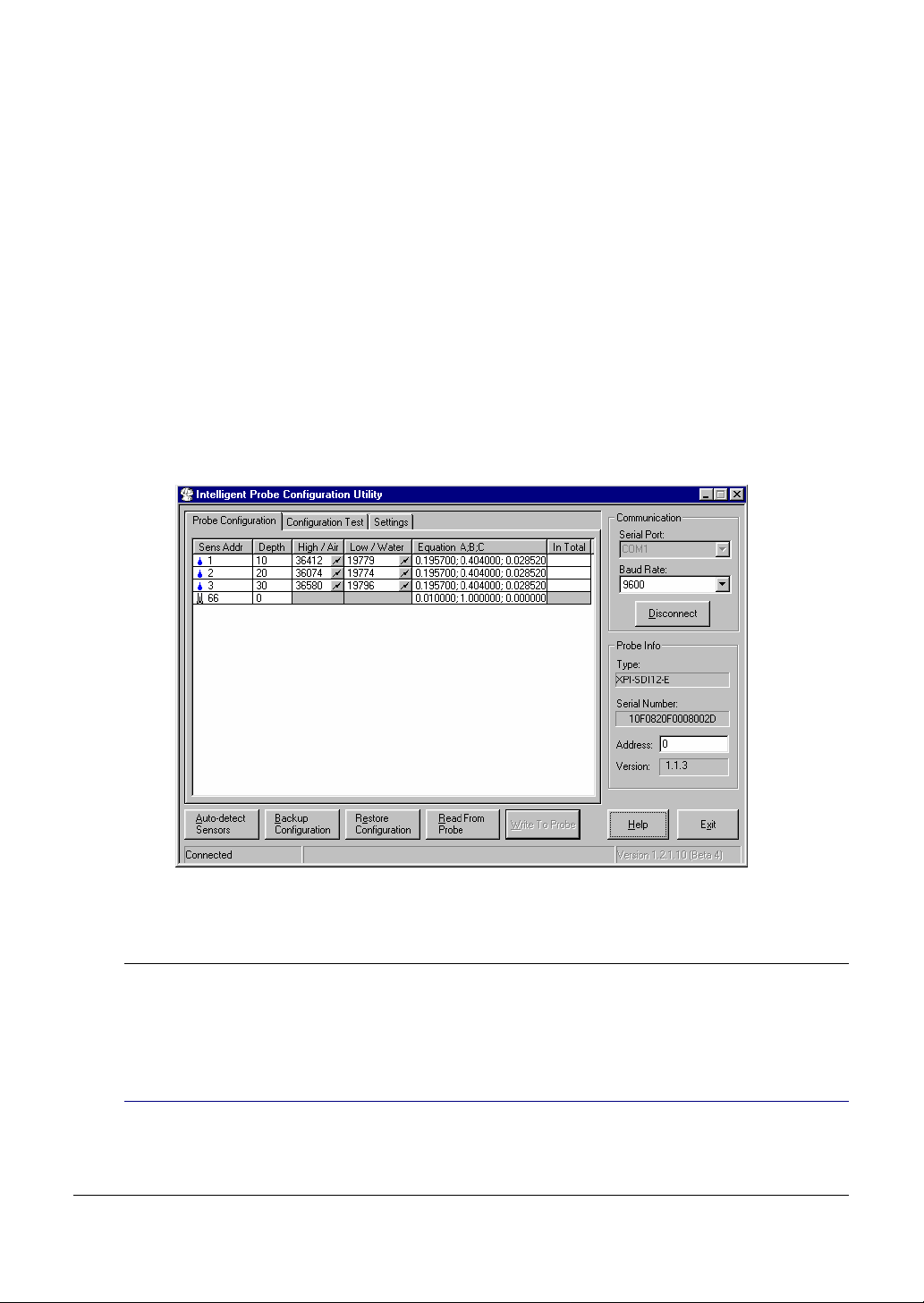
What is the Intelligent Probe Configuration Utility?
The Intelligent Probe Configuration Utility is provided to configure the EnviroSMART and EasyAG
SDI-12 probe interfaces with depth location, normalization values (air and water counts) and calibration
information for each sensor installed on the probe. This information is stored in non-volatile memory,
and is used to produce the calculated value (value that has been processed via the interfaces calibration
formula) from each sensor on the probe.
Communication between the Intelligent Probe Configuration Utility and the EnviroSMART and
EasyAG SDI-12 probe interface is done using the Intelligent Probe Configuration Utility cable from a
computers communication port to the probe interfaces TTL port.
Note: Temperature Sensors are currently not supported by the EnviroSMART and EasyAG SDI-12
probe interface.
Note: Information stored in non-volatile memory will not be lost when power is removed from the
SDI-12 probe interface.
Figure 1: Intelligent Probe Configuration Utility software
Setting the Probe Configuration
The Intelligent Probe Configuration Utility is provided to configure the EnviroSMART and EasyAG
SDI-12 probe interfaces with depth location, normalization values (air and water counts) and
calibration.
Auto-detect Sensors
Auto-detect Sensors will detect all sensors currently installed on the probe. After the sensors are
detected the configuration information (including type of sensor) will be displayed in the Probe
Configuration list.
Copyright © 1991 – 2003 Sentek Pty Ltd All rights reserved Page 2
Page 8

EnviroSMART & EasyAG SDI-12 Probe Manual
All sensor information must be valid before the configuration can be written to the probe.
Normalizing Sensors
Normalization is the setting of the range over which the sensor is effective. For example, soil moisture
sensors have a range bounded by the 2 extremes, air and water. The normalization process is necessary
to adjust for any variances that may occur during the production of the sensor.
Changing the Calibration Information
The sensor coefficients cell is used to store A, B and C coefficients. The coefficients are entered in A, B
then C order, separated by semicolons.
Setting the SDI-12 Address
The address of the probe should be in the range “0” to “9”, “A” to “Z” and “a” to “z”.
Copyright © 1991 – 2003 Sentek Pty Ltd All rights reserved Page 3
Page 9

EnviroSMART & EasyAG SDI-12 Probe Manual
SDI-12 Probe Interface
About setting up the EnviroSMART® and EasyAG® SDI-12 probe
interface
This section provides information on setting up the EnviroSMART and EasyAG SDI-12 probe
interfaces.
Why do I need to configure the SDI-12 probe interface?
The EnviroSMART and EasyAG SDI-12 probe interface must be configured to ensure valid
information is reported to the data logger when data is requested. This information includes the
number of sensors, normalization values (air and water counts) and calibration information.
By default, each SDI-12 probe interface is supplied with an SDI-12 address of “0”. If multiple probes
are to be installed on an SDI-12 bus, each SDI-12 probe interface must be assigned a unique address
(see section Addresses).
Warning!
Incorrect configuration information stored in the EnviroSMART or EasyAG SDI-12 probe interface will result in
incorrect volumetric water content (mm/10cm) readings being reported to the controlling device.
For more information on setting up the EnviroSMART and EasyAG SDI-12 probe interface, refer to
the Intelligent Probe Configuration Utility online help.
Copyright © 1991 – 2003 Sentek Pty Ltd All rights reserved Page 4
Page 10

EnviroSMART & EasyAG SDI-12 Probe Manual
SDI-12 Communication
About the SDI-12 Communication
This section provides information about the SDI-12 communication protocol used by the
EnviroSMART and EasyAG SDI-12 probe interfaces.
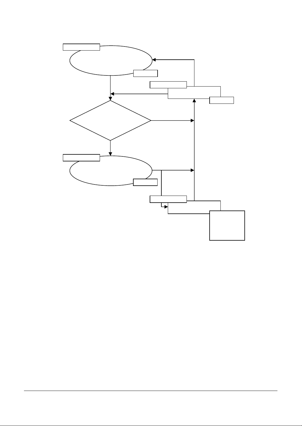
Power Sequence
Figure 2 shows the power consumption modes of the EnviroSMART and EasyAG SDI-12 probe
interface during communication with an SDI-12 compatible device.
The EnviroSMART and EasyAG SDI-12 probe interface, at power up, will remain in standby mode
for fifteen(15) seconds. If a break is not received, the probe interface will be placed in sleep mode.
An SDI-12 compatible device will send a break to wake all SDI-12 probe interfaces on the SDI-12 bus
before a command is sent. When this break is received, the EnviroSMART and EasyAG SDI-12
probe interface will then be placed in standby mode, ready to communicate with the controlling device.
The probe interface will remain in standby mode while the command is being processed. If a break (and
valid communication) is not received within fifteen(15) seconds of the last command, the
EnviroSMART and EasyAG SDI-12 probe interface will be placed back into sleep mode.
During a request to sample data, the EnviroSMART and EasyAG SDI-12 probe interface will sample
all sensors on the probe (sampling mode), then be placed into standby mode.
For more information on SDI-12 operation, visit www.sdi-12.org.
Note: Valid communication must have an SDI-12 address included in the command that matches that
of the probe interface, and in the format of a valid SDI-12 command.
Copyright © 1991 – 2003 Sentek Pty Ltd All rights reserved Page 5
Page 11
EnviroSMART & EasyAG SDI-12 Probe Manual
EnviroSMART
or
process command
valid
received?
sleep mode
EasyAG SDI-12 probe
interface in sleep mode
break
250µA
break
standby mode
15 second timeout
66mA
communication
no
yes
standby mode
(including response)
66mA
sampling mode
sample sensors
100mA
(Moisture)
130mA
(Salinity)
Figure 2: EnviroSMART® and EasyAG® SDI-12 probe interface communication power sequence
Timing
Figure 3 shows voltage levels on the SDI-12 line during transmission of an Acknowledge Active
command (a!) using the “?” (wildcard) address.
After the break condition has been sent to the EnviroSMART or EasyAG SDI-12 probe interface by
holding the line high (above 3.5V, spacing) for 12mS, the line is held low (below 1 V, marking) for a
minimum of 8.3mS before the first character is transmitted.
Each character transmitted consists of a Start Bit (spacing), followed by 7 data bits, followed by an even
parity bit, followed by a stop bit (marking). Characters are transmitted least significant bit (LSB) first
with each bit in the character being 0.833mS wide.
Copyright © 1991 – 2003 Sentek Pty Ltd All rights reserved Page 6
Page 12

EnviroSMART & EasyAG SDI-12 Probe Manual
In this example shown in Figure 3, there is no inter-character gap sent by the SDI-12 probe interface.
The start bit for the second character follows immediately after the stop bit (marking) from the first
character.
Note: The EnviroSMART and EasyAG SDI-12 probe interface will permit up to 4 bit-times between
characters before rejecting the command.
?=3F !=21
Spacing Level
Break Min 12 mS
Marking 8.4 mS
Bit Number:
Bit Value:
Marking Level
1 2 3 4 5 6 7 8 9 10 1 2 3 4 5 6 7 8 9 10
1 1 1 1 1 1 0 0 1 0 0 0 0 1 0 0
Intervals approx 0.8mS (1 bit time)
Figure 3: Voltage levels on the SDI-12 line during an Acknowledge Active command (a!)
Following the terminating character (!) of the command, the controlling device must release the line
within 6.5mS. The EnviroSMART and EasyAG SDI-12 probe interface will hold the line at the
marking level for a minimum of 8.33mS before transmitting the first character of the response.
Addresses
The EnviroSMART and EasyAG SDI-12 probe interface accepts SDI-12 addresses in the range “0”
to “9”, “A” to “Z” and “a” to “z”. Setting the probe interface address can be done using the Change
Address command (aAb!) (see SDI-12 Commands Supported) or using the Intelligent Probe
Configuration Utility.
3.5V
1.0V
Note: If the new address is invalid, the current address will be kept.
Note: The probe interface will remain unresponsive for approximately 30 ms while the new address is
saved in non-volatile memory.
Note: The probe interface supports “?” (wildcard) as an address only for the Acknowledge Active
command (a!).
Copyright © 1991 – 2003 Sentek Pty Ltd All rights reserved Page 7
Page 13

EnviroSMART & EasyAG SDI-12 Probe Manual
Data Reading
The EnviroSMART and EasyAG SDI-12 probe interfaces accept the Start Measurement command
(aM! or aMn!) and Start Concurrent Measurement command (aC! or aCn!) for obtaining calibrated
values from the probes sensors.
Note: The EnviroSMART and EasyAG SDI-12 probe interfaces do not support the Continuous
Measurement command (aRn!). The probe will respond with its address followed by <CR><LF> in
response to this command.
The EnviroSMART and EasyAG SDI-12 probe interface returns sensor values in sensor depth order,
starting at the shallowest depth (i.e. 10 cm). A sensor with a depth of zero (an un-configured sensor)
will not be reported by the SDI-12 probe interface.
As the Start Measurement command (aM! or aMn!) reports how many sensor readings to expect, the
controlling device should issue Send Data commands (aDn!) until it either receives a reply with no data
(a<CR><LF>, indicating that the probe abandoned sampling, or that all data has been received), or
until it has received all of specified number of sensor values.
Note: The controlling device may choose not to issue all Send Data commands (aDn!) when retrieving
the data.
Note: The EnviroSMART and EasyAG SDI-12 probe interface currently uses a fixed format of “sign
followed by three digits, followed by the decimal point, followed by four decimal digits” (±nnn.nnnn)
to return readings. This may change in future issues of the EnviroSMART or EasyAG SDI-12 probe
interface firmware (software should not rely on this fixed format).
Note: Valid soil moisture values will always be in the range +000.0000 to +101.0000. Soil moisture data
which would result in values in the range -0.1 to 0.0 will be returned as +000.0000. Any soil moisture
values outside of this range (caused by faulty sensors, incorrect probe installation or configuration) will
be returned as -999.9999. A failed sensor will also return a value of -999.9999.
Data Reading using the Start Measurement Command (aM! or aMn!)
The following table shows the allocation of the Start Measurement commands (aM! or aMn!):
aM! Read Soil Moisture values 1 – 9
aM1! Read Soil Moisture values 10 – 16
aM2! Read Salinity values 1 – 9
aM3! Read Salinity values 10 – 16
Note: Start Measurement commands (aM! or aMn!) above “aM3!” will result in a response of
“a0000<CR><LF>”.
Soil Moisture Values (aM! and aM1!)
The Start Measurement command (aM! or aMn!) allows up to nine(9) values to be returned. As it is
possible to have up to sixteen(16) soil moisture values from the EnviroSMART SDI-12 probe
interface, two(2) Start Measurement commands (aM! or aMn!), “aM!” and “aM1!” are required. The
Send Data command (aDn!) may return up to three(3) values.
Copyright © 1991 – 2003 Sentek Pty Ltd All rights reserved Page 8
Page 14

EnviroSMART & EasyAG SDI-12 Probe Manual
Command Response
aM! a0139<CR><LF>
The response indicates that 9 soil moisture values will be available within a time of 13 seconds. After
approximately 10 seconds the probe will issue a Service Request (a<CR><LF>, where “a” is the probe
address). The controlling device will then issue Send Data commands (aDn!) to read the values.
Command Response
aD0! a+001.0000+001.1234+000.0200<CR><LF>
aD1! a+000.1234+000.0000+123.1234<CR><LF>
aD2! a+010.1200+000.1243+044.8750<CR><LF>
If there are more than 9 soil moisture values, a further Start Measurement command (aM! or aMn!)
must be issued.
Command Response
aM1! a0117<CR><LF>
The response indicates that another 7 soil moisture values will be available within a time of 11 seconds.
After approximately 8 seconds, the probe will issue a Service Request (a<CR><LF>, where “a” is the
probe address), and the controlling device will then issue Send Data commands (aDn!) to read the
values.
Command Response
aD0! a+002.0010+003.1234+001.0200<CR><LF>
aD1! a+011.1234+001.0100+011.3344<CR><LF>
aD2! a+012.0230<CR><LF>
Note: The Send Data commands (aDn!) must be issued in increasing order.
Salinity Values (aM2! and aM3!)
The Start Measurement command (aM! or aMn!) allows up to nine(9) values to be returned. As it is
possible to have up to sixteen(16) salinity values from the EnviroSMART SDI-12 probe interface,
two(2) Start Measurement commands (aM! or aMn!), “aM2!” and “aM3!” are required. The Send Data
command (aDn!) may return up to three(3) values.
Command Response
aM2! a0239<CR><LF>
The response indicates that 9 salinity values will be available within a time of 23 seconds. After
approximately 21 seconds the probe will issue a Service Request (a<CR><LF>, where “a” is the probe
address). The controlling device will then issue Send Data commands (aDn!) to read the values.
Command Response
Copyright © 1991 – 2003 Sentek Pty Ltd All rights reserved Page 9
Page 15
EnviroSMART & EasyAG SDI-12 Probe Manual
aD0! a+001.0000+001.1234+000.0200<CR><LF>
aD1! a+000.1234+000.0000+123.1234<CR><LF>
aD2! a+010.1200+000.1243+044.8750<CR><LF>
If there are more than 9 salinity values, a further Start Measurement command (aM! or aMn!) must be
issued.
Command Response
aM3! a0187<CR><LF>
The response indicates that another 7 salinity values will be available within a time of 18 seconds. After
approximately 16 seconds, the probe will issue a Service Request (a<CR><LF>, where “a” is the probe
address), and the controlling device will then issue Send Data commands (aDn!) to read the values.
Command Response
aD0! a+002.0010+003.1234+001.0200<CR><LF>
aD1! a+011.1234+001.0100+011.3344<CR><LF>
aD2! a+012.0230<CR><LF>
Note: The Send Data commands (aDn!) must be issued in increasing order.
Data Reading using the Start Concurrent Measurement Command (aC! or aCn!)
The following table shows the allocation of sensors for the Start Concurrent Measurement commands
(aC! or aCn!):
aC! Read Soil Moisture values 1 – 16
aC1! Read Salinity values 1 – 16
aC2! Reserved
aC3! Reserved
aC4! Read Soil Moisture Configuration values C constants 1 – 16
aC5! Read Soil Moisture Configuration values B constants 1 – 16
aC6! Read Soil Moisture Configuration values A constants 1 – 16
aC7! Reserved
aC8! Read Salinity Sensor Depth values 1 – 16
aC9! Read Soil Moisture Sensor Depth values 1 – 16
Note: Start Concurrent Measurement commands (aC! or aCn!) “aC2!”, “aC2!” and “aC7!” will result in
a response of “a0000<CR><LF>”.
Copyright © 1991 – 2003 Sentek Pty Ltd All rights reserved Page 10
Page 16
EnviroSMART & EasyAG SDI-12 Probe Manual
Soil Moisture Values (aC!)
The Start Concurrent Measurement command (aC! or aCn!) “aC!” allows all soil moisture values to be
sampled with a single command. Values are gathered in the same way as for the Start Measurement
command (aM! or aMn!), but the Send Data command (aDn!) may return up to eight(8) values.
Command Response
aC! A02116<CR><LF>
The response indicates that 16 soil moisture values will be available after a time of 21 seconds. The
controlling device will then issue Send Data commands (aDn!) to read the values.
Command Response
aD0! a+001.0000+001.1234+000.0200+000.1234+000.0000
+123.1234+010.1200+000.1243<CR><LF>
aD1! a+044.8750+002.0010+003.1234+001.0200+011.1234
+001.0100+001.0100+011.3344<CR><LF>
Note: The EnviroSMART and EasyAG SDI-12 probe interface will not issue a service request for this
command.
Note: Refer to notes on Start Measurement (aM! or aMn!) command above.
Salinity Values (aC1!)
The Start Concurrent Measurement command (aC! or aCn!) “aC1!” allows all salinity values to be
sampled with a single command. Values are gathered in the same way as for the Start Measurement
command (aM! or aMn!), but the Send Data command (aDn!) may return up to eight(8) values.
Command Response
aC1! A03616<CR><LF>
The response indicates that 16 salinity values will be available after 36 seconds. The controlling device
will then issue Send Data commands (aDn!) to read the values.
Command Response
aD0! a+001.0000+001.1234+000.0200+000.1234+000.0000
+123.1234+010.1200+000.1243<CR><LF>
aD1! a+044.8750+002.0010+003.1234+001.0200+011.1234
+001.0100+001.0100+011.3344<CR><LF>
Note: The EnviroSMART and EasyAG SDI-12 probe interface will not issue a service request for this
command.
Copyright © 1991 – 2003 Sentek Pty Ltd All rights reserved Page 11
Page 17
EnviroSMART & EasyAG SDI-12 Probe Manual
Note: Refer to notes on Start Measurement (aM! or aMn!) command above.
Soil Moisture Configuration Values (aC4!, aC5! and aC6!)
The Start Concurrent Measurement commands (aC! or aCn!) “aC4!”, “aC5!” and “aC6!” allow all soil
moisture A, B and C constants to be sampled with a single command. Values are gathered in the same
way as for the Start Measurement command (aM! or aMn!), but the Send Data command (aDn!) may
return up to eight(8) values.
A Constants are retrieved with the Start Concurrent Measurement command (aC! or aCn!) “aC6!”
Command Response
aC6! A00016<CR><LF>
The response indicates that 16 A constant values will be available immediately. The controlling device
will then issue Send Data commands (aDn!) to read the values.
Command Response
aD0! a+000.1957+000.1957+000.1957+000.1957+000.1957
+000.1957+000.1957+000.1957<CR><LF>
aD1! a+000.1957+000.1957+000.1957+000.1957+000.1957
+000.1957+000.1957+000.1957<CR><LF>
B Constants are retrieved with the Start Concurrent Measurement command (aC! or aCn!) “aC5!”
Command Response
aC5! A00016<CR><LF>
The response indicates that 16 B constant values will be available immediately. The controlling device
will then issue Send Data commands (aDn!) to read the values.
Command Response
aD0! a+000.4040+000.4040+000.4040+000.4040+000.4040
+000.4040+000.4040+000.4040<CR><LF>
aD1! a+000.4040+000.4040+000.4040+000.4040+000.4040
+000.4040+000.4040+000.4040<CR><LF>
C Constants are retrieved with the Start Concurrent Measurement command (aC! or aCn!) “aC4!”
Command Response
aC4! A00016<CR><LF>
Copyright © 1991 – 2003 Sentek Pty Ltd All rights reserved Page 12
Page 18
EnviroSMART & EasyAG SDI-12 Probe Manual
The response indicates that 16 C constant values will be available immediately. The controlling device
will then issue Send Data commands (aDn!) to read the values.
Command Response
aD0! a+000.0285+000.0285+000.0285+000.0285+000.0285
+000.0285+000.0285+000.0285<CR><LF>
aD1! a+000.0285+000.0285+000.0285+000.0285+000.0285
+000.0285+000.0285+000.0285<CR><LF>
Note: The EnviroSMART and EasyAG SDI-12 probe interface will not issue a service request for this
command.
Note: Refer to notes on Start Measurement (aM! or aMn!) command above.
Soil Moisture Sensor Depth Values (aC9!)
The Start Concurrent Measurement command (aC! or aCn!) “aC9!” allows all soil moisture depth values
to be sampled with a single command. Values are gathered in the same way as for the Start
Measurement command (aM! or aMn!), but the Send Data command (aDn!) may return up to eight(8)
values.
Command Response
aC9! A00016<CR><LF>
The response indicates that 16 soil moisture depth values will be available immediately. The controlling
device will then issue Send Data commands (aDn!) to read the values.
Command Response
aD0! a+010.0000+020.0000+030.0000+040.0000+050.0000
+060.0000+070.0000+080.0000<CR><LF>
aD1! a+090.0000+100.0000+110.0000+120.0000+130.0000
+140.0000+150.0000+160.0000<CR><LF>
Note: The EnviroSMART and EasyAG SDI-12 probe interface will not issue a service request for this
command.
Note: Refer to notes on Start Measurement (aM! or aMn!) command above.
Salinity Sensor Depth Values (aC8!)
The Start Concurrent Measurement command (aC! or aCn!) “aC9!” allows all salinity depth values to be
sampled with a single command. Values are gathered in the same way as for the Start Measurement
command (aM! or aMn!), but the Send Data command (aDn!) may return up to eight(8) values.
Command Response
aC9! A00016<CR><LF>
Copyright © 1991 – 2003 Sentek Pty Ltd All rights reserved Page 13
Page 19

EnviroSMART & EasyAG SDI-12 Probe Manual
The response indicates that 16 salinity depth values will be available immediately. The controlling device
will then issue Send Data commands (aDn!) to read the values.
Command Response
aD0! a+010.0000+020.0000+030.0000+040.0000+050.0000
+060.0000+070.0000+080.0000<CR><LF>
aD1! a+090.0000+100.0000+110.0000+120.0000+130.0000
+140.0000+150.0000+160.0000<CR><LF>
Note: The EnviroSMART and EasyAG SDI-12 probe interface will not issue a service request for this
command.
Note: Refer to notes on Start Measurement (aM! or aMn!) command above.
Identification
The EnviroSMART and EasyAG SDI-12 probe interface will respond with a string of the following
format when sent the Send Identification command (aI!):
allccccccccmmmmmmvvvxxxxxxxxxxxx<CR><LF>
Example:
012SENTEK XPI 103C42238000000<CR><LF>
where: 0 The sensor address
12 SDI-12 version number, version 1.2
SENTEK Company name
XPI Model name (XPI for EnviroSMART, IPI for EasyAG)
103 Model version, version 1.0.3
C42238000000 Serial number
Note: The EnviroSMART and EasyAG SDI-12 probe interface firmware version consists of a
major/minor/sub-minor number. Since SDI-12 allocates only three characters, when any number
exceeds 9, the characters “A” to “Z”, then “a” to “z” is used. If the number exceeds 61 an asterisk (*) is
shown.
The EnviroSMART and EasyAG SDI-12 probe interface stores a 64-bit serial number. The Intelligent
Probe Configuration Utility will report all 64 bits as a hexadecimal number. The first two digits (8 bits)
of this serial number are always “10”, and the last two digits (8 bits) are a Cyclic Redundancy Check
(CRC). The serial number reported via SDI-12 omits the first and last 8 bits, providing the remaining 48
bits as the serial number.
The serial number for the above example is:
10C4223800000097 As reported by Intelligent Probe Configuration Utility
C42238000000 As reported by SDI-12
C42238 As shown on the SDI-12 probe interface Serial No.
Copyright © 1991 – 2003 Sentek Pty Ltd All rights reserved Page 14
Page 20

EnviroSMART & EasyAG SDI-12 Probe Manual
Supported Commands
SDI-12 Commands Supported
The following commands are supported by the EnviroSMART and EasyAG SDI-12 probe interfaces:
Command Name Response
a!
aI!
aAb!
aM!
aMn!
aC!
aCn!
Acknowledge
Active
Send
Identification
Change Address
Start
Measurement
Start
Measurement
n in range “1”
- “3”
Concurrent
Measurement
Concurrent
Measurement
n in range “1”
- “9”
a<CR><LF>
The probe interface address
allccccccccmmmmmmvvvxxxxxxxxxxxx<CR><LF>
Identification information
a<CR><LF>
The probe interface address
atttn<CR><LF>
Delay (ttt) in seconds and number of
values (n) up to 9
atttn<CR><LF>
Delay (ttt) in seconds and number of
values (n) up to 9
Note: A response of a0000<CR><LF> is
provided indicating all values are
served by previous Start Measurement
commands (aMn!)
atttnn<CR><LF>
Delay (ttt) and number of values (nn) up
to 16
atttnn<CR><LF>
Delay (ttt) and number of values (nn) up
to 16
Note: A response of a0000<CR><LF> is
provided indicating all values are
served by previous Start Concurrent
Measurement (aCn!) commands
aDn!
Send Data
Refer to “Data Reading” section
n in range “0”
- “9”
aV!
Start
a0000<CR><LF>
verification
aRn!
Continuous
Measurement
a<CR><LF>
Not supported
Probe interface will respond with its
address
Copyright © 1991 – 2003 Sentek Pty Ltd All rights reserved Page 15
Page 21

EnviroSMART & EasyAG SDI-12 Probe Manual
Extended Commands Supported
There are no extended commands supported by the EnviroSMART and EasyAG SDI-12 probe
interface.
Copyright © 1991 – 2003 Sentek Pty Ltd All rights reserved Page 16
Page 22

EnviroSMART & EasyAG SDI-12 Probe Manual
EnviroSMART® Technical Specifications
SDI-12 Version supported: Version 1.2
PCB Revision: 2.0
SDI-12 Interface connector type: Brand: Phoenix Contact
MC 1,5/3-ST-3,5 (Socket)
EMC 1,5/3-G-3,5 (Plug)
SDI-12 Interface pin configuration:
1 +Vin
2 Ground
3 SDI-12 data
Voltage Supply (SDI-12 +Vin): 9 – 20 Volts DC (12 Volts DC @ >200mA recommended)
SDI-12 Interface baud rate: 1200 bits per second
TTL Interface connector type: Brand: JST
B 6B-PH-K (Socket)
PHR- 6 (Plug), SPH-002T-P0.5S (Crimp connectors)
TTL Interface pin configuration:
1 +Vcc
2 Transmit data (Tx)
3 Receive data (Rx)
4 Programming Jumper
5 Programming Jumper
6 Ground
Voltage Supply (TTL +Vcc): 5 Volts, supplied by the EnviroSMART probe interface
TTL Interface baud rate: 1200, 2400, 9600 (default), 19200 and 38400 bits per second
Copyright © 1991 – 2003 Sentek Pty Ltd All rights reserved Page 17
Page 23

EnviroSMART & EasyAG SDI-12 Probe Manual
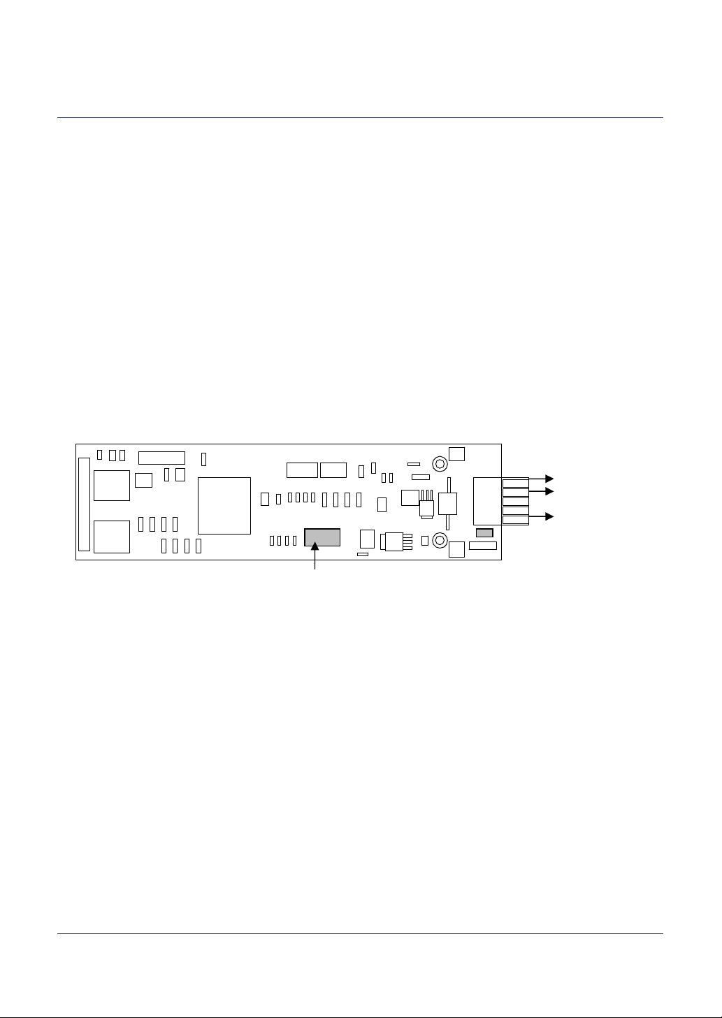
SDI-12 data
Ground
+V
in
Total current consumption: 250µA @ sleep
66mA @ standby
105mA @ sampling (Moisture)
130mA @ sampling (TriSCAN™)
Time to sample 1 sensor: 1.2 seconds maximum (Moisture only)
2.4 seconds maximum (TriSCAN™)
Maximum sensors supported: 16 Moisture sensors or
16 TriSCAN™ sensors
1 6
3
1
TTL Port
Figure 4: EnviroSMART® SDI-12 probe interface board layout
Copyright © 1991 – 2003 Sentek Pty Ltd All rights reserved Page 18
Page 24

EnviroSMART & EasyAG SDI-12 Probe Manual
EasyAG® Technical Specifications
SDI-12 Version supported: Version 1.2
PCB Revision: 0.0
SDI-12 Interface connector type: Brand: Phoenix Contact
MPT0.5/3-2.54
SDI-12 Interface pin configuration:
1 +Vin
2 Ground
3 SDI-12 data
Voltage Supply (SDI-12 +Vin): 9 – 20 Volts DC (12 Volts DC @ >200mA recommended)
SDI-12 Interface baud rate: 1200 bits per second
TTL Interface connector type: Brand: JST
B 6B-PH-K (Socket)
PHR- 6 (Plug), SPH-002T-P0.5S (Crimp connectors)
TTL Interface pin configuration:
1 +Vcc
2 Transmit data (Tx)
3 Receive data (Rx)
4 Programming Jumper
5 Programming Jumper
6 Ground
Voltage Supply (TTL +Vcc): 5 Volts, supplied by the EasyAG probe interface
TTL Interface baud rate: 1200, 2400, 9600 (default), 19200 and 38400 bits per second
Copyright © 1991 – 2003 Sentek Pty Ltd All rights reserved Page 19
Page 25

EnviroSMART & EasyAG SDI-12 Probe Manual
Total current consumption: 250µA @ sleep
66mA @ standby
102mA @ sampling (Moisture)
126mA @ sampling (TriSCAN™)
Time to sample 1 sensor: 1.2 seconds maximum (Moisture only)
2.4 seconds maximum (TriSCAN™)
Maximum sensors supported: 5 Moisture sensors or
5 TriSCAN™ sensors
TTL Port
6 1
3
SDI12 data
Ground
+Vin
1
Figure 5: EasyAG® SDI-12 probe interface board layout
Copyright © 1991 – 2003 Sentek Pty Ltd All rights reserved Page 20
Page 26

Circuit Information
G125GW
0V
0V
+V IN
1
2
SDI-12
Phoenix
EMC 1,5/3-G-3,5 (EnviroSMART)
MPT0.5/3-2.54 (EasyAG)
3
MF-R090
N81-A350X
VSUP
SMCJ22A
GND
MF-R010 510R
EnviroSMART & EasyAG SDI-12 Probe Manual
1
VCC
5
4
3
GND
74HC14
3.3nF
GND GND GND
200K SML4737
510R
74HC1
2
8 9
6 PIN
MICROSPOX
+V CC
PROGRAMMING JUMPER
TXD1
RXD1
PROGRAMMING JUMPER
Figure 6: SDI-12 interface circuit diagram
74HC14 74HC14
1
2
3
4
5
6
VCC
TTL-TXD1
TTL-RXD1
MD1
BAR43
GND
8 9 6 5
13 12 11 10
1M
VCC
Figure 7: TTL interface circuit diagram
74HC14 74HC14
Copyright © 1991 – 2003 Sentek Pty Ltd All rights reserved Page 21
Page 27
Revision Information
SDI-12 data
EnviroSMART® Revision Information
PCB Revision 1.2
• Interface connector type:
Brand: Phoenix Contact
FK-MC 0,5/5-ST-2,5 (Socket)
MC 0,5/5-G-2,5 (Plug)
• Interface pin configuration:
1. +Vin
2. Reserved
3. Reserved
4. Ground
5. SDI-12 data
Figure 8: EnviroSMART® SDI-12 probe interface old revision board layout
TTL Port
1 6
EnviroSMART & EasyAG SDI-12 Probe Manual
5
1
Ground
N.C
N.C
+Vin
EasyAG® Revision Information
No previous revisions.
Copyright © 1991 – 2003 Sentek Pty Ltd All rights reserved Page 22
Page 28

EnviroSMART & EasyAG SDI-12 Probe Manual
Appendix A – Soil Moisture Management
What soil volume does the SDI-12 probe interface measure at a
single sensor?
At a single depth level, a sensor on the probe records volumetric water content from a soil volume
outside the access tube, which has a sphere of influence of:
⇒ 10cm vertical height
⇒ 5-10cm radial distance from the outer wall of the access tube
What are the water units?
If a calibrated sensor reads one(1) millimetre, there is one(1) millimetre of volumetric water content in a
soil volume 10cm deep.
Q. What does 1mm volumetric water content / 10cm soil depth mean?
A. You require one(1) litre of water to cover one(1) square meter (m²) to a soil depth of one(1)
millimetre.
Figure 9: Measurements using metric units
Copyright © 1991 – 2003 Sentek Pty Ltd All rights reserved Page 23
Page 29

EnviroSMART & EasyAG SDI-12 Probe Manual
Figure 10: Measurements using imperial units
What part of the soil profile do multiple sensors on the probe
measure?
Probes in almost all cases have more than one sensor to monitor the depth of irrigation and the depth
of the root zone. The first sensor is located at a soil depth of 10cm (if the datum plate of the top cap
sits on ground level) measuring effectively the soil profile slice of 5-15cm depth. The next sensor is
located at 20 cm measuring effectively 15 –25cm soil depths. With further sensors at 10cm intervals on
the probe rod, the measurement depth would be respectively (25-35cm, 35-45cm and so on).
If you raise the datum plate of the top-cap 5cm above the ground surface, placing the center of the first
sensor effectively at 5cm soil depth, the sphere of influence of the sensor will measure a soil slice from
0-10cm. For the other sensors at 10cm depth intervals on the probe rod, the measurement depth would
be respectively (20-30cm, 30-40cm and so on).
Figure 11: Measurements of multiple sensors on the probe
Copyright © 1991 – 2003 Sentek Pty Ltd All rights reserved Page 24
Page 30

Appendix B – Salinity Management
Please refer to the “TriSCAN™ Agronomic User Manual”
EnviroSMART & EasyAG SDI-12 Probe Manual
Copyright © 1991 – 2003 Sentek Pty Ltd All rights reserved Page 25
 Loading...