

Page 1
A150 Desiccated Case
4/11
Copyright © 2011
Campbell Scientific, Inc.
Page 2

Warranty and Assistance
PRODUCTS MANUFACTURED BY CAMPBELL SCIENTIFIC, INC. are
warranted by Campbell Scientific, Inc. (“Campbell”) to be free from defects in
materials and workmanship under normal use and service for twelve (12) months
from date of shipment unless otherwise specified on the corresponding Campbell
invoice. Batteries, fine-wire thermocouples, desiccant, and other consumables have
no warranty. Campbell's obligation under this warranty is limited to repairing or
replacing (at Campbell's option) defective products, which shall be the sole and
exclusive remedy under this warranty. The customer shall assume all costs of
removing, reinstalling, and shipping defective products to Campbell. Campbell
will return such products by surface carrier prepaid within the continental United
States of America. To all other locations, Campbell will return such products best
way CIP (Port of Entry) INCOTERM
apply to any Campbell products which have been subjected to modification,
misuse, neglect, improper service, accidents of nature, or shipping damage. This
warranty is in lieu of all other warranties, expressed or implied. The warranty for
installation services performed by Campbell such as programming to customer
specifications, electrical connections to products manufactured by Campbell, and
product specific training, is part of Campbell’s product warranty. CAMPBELL
EXPRESSLY DISCLAIMS AND EXCLUDES ANY IMPLIED WARRANTIES
OF MERCHANTABILITY OR FITNESS FOR A PARTICULAR PURPOSE.
Campbell is not liable for any special, indirect, incidental, and/or consequential
damages.
Products may not be returned without prior authorization. The following contact
information is for US and International customers residing in countries served by
Campbell Scientific, Inc. directly. Affiliate companies handle repairs for customers
within their territories. Please visit www.campbellsci.com to determine which
Campbell Scientific company serves your country.
®
2010, prepaid. This warranty shall not
To obtain a Returned Materials Authorization (RMA), contact Campbell Scientific,
Inc., phone (435) 753-2342. After an applications engineer determines the nature
of the problem, an RMA number will be issued. Please write this number clearly
on the outside of the shipping container. Campbell Scientific's shipping address is:
CAMPBELL SCIENTIFIC, INC.
RMA#_____
815 West 1800 North
Logan, Utah 84321-1784
For all returns, the customer must fill out a “Declaration of Hazardous Material and
Decontamination” form and comply with the requirements specified in it. The form
is available from our website at
must be either emailed to repair@campbellsci.com
Campbell Scientific will not process any returns until we receive this form. If the
form is not received within three days of product receipt or is incomplete, the
product will be returned to the customer at the customer’s expense. Campbell
Scientific reserves the right to refuse service on products that were exposed to
contaminants that may cause health or safety concerns for our employees.
www.campbellsci.com/repair
or faxed to 435-750-9579.
. A completed form
Page 3

A150 Table of Contents
PDF viewers note: These page numbers refer to the printed version of this document. Use
the Adobe Acrobat® bookmarks tab for links to specific sections.
1. Function........................................................................1
1.1 Typical Applications.................................................................................1
1.2 Compatibility ............................................................................................1
2. Physical Description ...................................................2
3. Specifications ..............................................................3
4. Sensor Hook-up and Example Diagrams...................3
4.1 #26972 with Stripped and Tinned Continuation Cable ............................4
4.2 #22018 PWENC Connector......................................................................4
4.3 #19520 CWS900 Connector.....................................................................5
5. Installation....................................................................6
Figures
5.1 Mounting ..................................................................................................6
5.2 Wiring.......................................................................................................6
1. A150 Desiccated Case ................................................................................1
2. A150 Interior ..............................................................................................2
3. CWS900 Connector Pin-Out ......................................................................3
4. A150 with Continuation Cable ...................................................................4
5. A150 with PWENC Connector...................................................................4
6. Anemometer Wired to an A150..................................................................5
7. A150 with CWS900 Connector..................................................................5
8. A150 Wired for CS450 Pressure Sensor and CWS900 Connector ............5
i
Page 4

Page 5
A150 Desiccated Case
1. Function
1.1 Typical Applications
The A150 desiccated case is a small, self-contained junction box that allows a
sensor to be connected to a continuation cable, a PWENC connector, or a
CWS900 wireless sensor connector. Utilizing the A150, a sensor may be
incorporated into a wireless sensor network or may be attached to a prewired
enclosure.
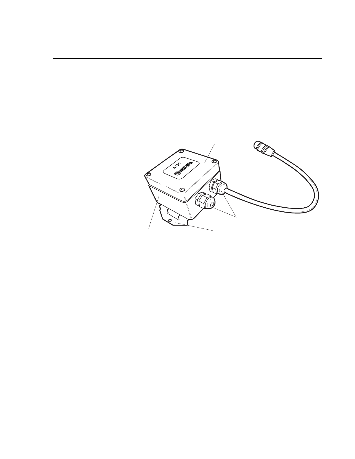
Lid
Cable Gland
Chassis
The A150 allows the CS450 and CS455 pressure transducers to be used
without the need to run a ventilation tube all the way to a datalogger enclosure.
The sensor cable with a ventilation tube terminates at the A150, which contains
a small vent and desiccant, while a second cable without a ventilation tube
completes the connection to the datalogger.
The A150 provides a way for a sensor to be included in a wireless sensor
network. The sensor is attached to the A150 junction box, and a second cable
attaches the A150 to a CWS900 wireless sensor interface. This allows the
sensor more flexibility and range than it would have if it were wired directly to
a datalogger.
1.2 Compatibility
As a junction box, the A150 is compatible with most sensors using six wires or
less. Sensors with multiple ground wires can use the included 5-position lever
nut to combine the grounds into a single wire connection.
Mounting Bracket
FIGURE 1. A150 Desiccated Case
1
Page 6

A150 Desiccated Case
T
NOTE
erminal Block
It is not recommended to insert more than one wire into each
connection on the terminal block. If it is necessary to combine
wires, use the 5-position lever nut to combine the wires, and then
insert the lead wire from the lever nut into the terminal block.
When used with a CWS900, the sensor can be used with sensors measuring
analog voltages, frequency, and pulse. The CWS900 can also provide
excitation voltage to a sensor through the A150.
Wire to Datalogger
or CWS900
Lever Nut
Vent
FIGURE 2. A150 Interior
2. Physical Description
The A150 has an 80 mm x 82 mm x 55 mm chassis. Four screws secure the lid
to the rest of the unit. A terminal block is mounted inside the chassis. A small
vent is located on the bottom of the chassis. The vent is protected by a GORE
filter, which prevents moisture and contaminants from entering the unit while
equalizing the interior air pressure to the current atmospheric pressure.
A mounting bracket is attached to the bottom of the chassis. The bracket is
used to fasten the A150 inside an enclosure or, with the included Velcro
to another location of the user’s choosing.
®
strap,
®
2
Page 7
A150 Desiccated Case
3. Specifications
Dimensions: 80 mm x 82 mm x 55 mm (3.15" x 3.228" x 2.171")
Temperature Range: -30ºC to +65ºC
Internal Protection Rating: IP 66 (International Standard IEC 60529)
Terminal Block Wire Gauges: 28–12
5-wire Lever Nut Wire Gauges: 28–12 (replacement part number 27373)
Cable Gland Min/Max Cable Diameter: 4.6 mm/7.9 mm (0.181"/0.312")
Desiccant Bag (1/2 Unit) Replacement Part Number: 905
®
Velcro
Humidity Indicator Card Replacement Part Number: 6571
Strap Replacement Part Number: 5487
4. Sensor Hook-up and Example Diagrams
There are three options available when ordering the A150. The first option
includes a stripped and tinned continuation cable. The length of this cable is
specified when ordering the A150.
The second option includes a PWENC connector, allowing the A150 to be
attached to prewired enclosures.
The third option includes a connector to attach the A150 to the CWS900
wireless sensor interface. The CWS900 completes the connection to the
datalogger through a wireless sensor network.
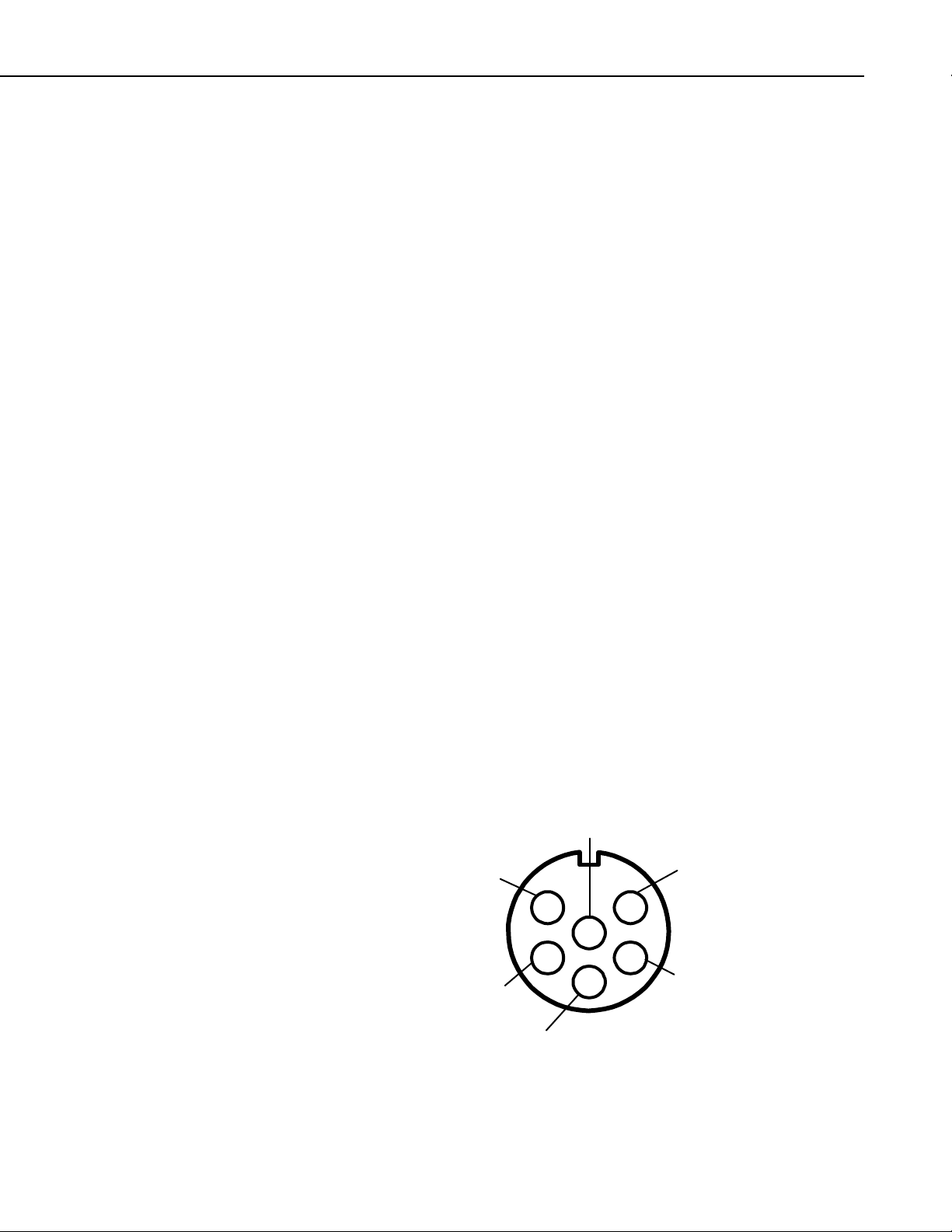
Figure 3 shows the pin-out of the CWS900 connector. Take care that the
sensor wires attached to the A150 correspond to the correct pins as shown in
the diagram.
Pin 6
SE2 or DIFF L
Pin 1 SE3
Pin 2 Pulse
Pin 5
SE1 or DIFF H
Pin 4 EX
(2.5V, 3.3V, or 5V)
Pin 3 Ground
FIGURE 3. CWS900 Connector Pin-Out
3
Page 8

A150 Desiccated Case
4.1 #26972 with Stripped and Tinned Continuation Cable
Figure 4 shows the A150 terminal block with a 26972 continuation wire
attached. This configuration allows a CS450 or other sensor to be attached to
the A150 while the pigtail wire completes the connection to the datalogger.
WHITE
BLUE
GREEN
RED
BLACK
BLACK
CLEAR
FIGURE 4. A150 with Continuation Cable
NOTE
Wire colors may vary between different sensors. It is up to the
installer to take into account any mismatched wire colors
between the sensor and pigtail wire when connecting wires to the
A150.
4.2 #22018 PWENC Connector
Figure 5 shows the A150 terminal block with a PWENC connector attached.
This configuration allows a CS450 or other sensor to be attached to the A150
while the PWENC connector completes the connection to a pre-wired
enclosure.
#26972 Cable w/ Tinned Wire Ends
4
BLACK
NOTE
WHITE
BLUE
GREEN
RED
BLACK
CLEAR
#26972 Cable
(Pin #)
1
2
3
#22018
PWENC Connector
4
5
6
FIGURE 5. A150 with PWENC Connector
When using the A150 to wire a sensor to a PWENC connector,
ensure the wiring inside the pre-wired enclosure corresponds
with the wiring from the sensor.
Figure 6 gives an example of an anemometer wired to an A150. Note that the
green wire in the PWENC connector must be connected to a datalogger’s pulse
input inside the enclosure for the signal to be measured.
Page 9

A150 Desiccated Case
W
A
r
Anemometer
BLACK Signal Pulse
HITE Signal Reference
CLEAR Shield
4.3 #19520 CWS900 Connector
WHITE
BLUE
GREEN
RED
BLACK
CLEAR
#26972 Cable
(Pin #)
1
2
3
#22018
PWENC Connector
4
5
6
FIGURE 6. Anemometer Wired to an A150
Figure 7 shows the A150 terminal block with a CWS900 attached. This
configuration allows a CS450 or other sensor to be attached to the A150 while
the CWS900 wireless sensor interface completes the connection to the wireless
sensor network.
WHITE
BLUE
GREEN
RED
BLACK
BLACK
CLEAR
#26972 C able
56(Pin #)
2
1
#19520
CWS900 Connector
4
3
Sensor RX (In)
Sensor T X (Ou t)
Power
Power GND
Digital GND
Shield
Ven t
FIGURE 7. A150 with CWS900 Connector
Figure 8 shows a CS450 connected to an A150. Note how multiple grounds
are combined into a single lead wire using the lever nut.
CS450
BLUE
WHITE
RED
BLACK
YELLOW
CLEAR
TUBE
N.C.
BLACK
N.C.
150Pressure Senso
WHITE
BLUE
GREEN
RED
BLACK
CLEAR
Terminates in A150 Enclosure
#26972 Cable
(Pin #)
5
2
1
#19520
CWS900 Connector
4
3
6
FIGURE 8. A150 Wired for CS450 Pressure Sensor and CWS900 Connector
5
Page 10

A150 Desiccated Case
5. Installation
5.1 Mounting
5.2 Wiring
The A150 provides two options for mounting. The first is to use the Velcro®
strap included with the A150. This allows the A150 to be secured to a small
mast, fencepost or other location where it is not possible to use mounting
screws.
The second option is to use the mounting bracket on the back of the A150.
This bracket allows the A150 to be mounted inside an enclosure or to another
flat surface, using two screws through the bracket to secure the A150.
To wire a sensor to the A150, route the sensor cable through the cable gland
and attach each wire to the terminal block adjacent to the corresponding wire to
the datalogger or CWS900. Use the lever nut to combine multiple ground
wires into a single wire connection. Consult the documentation included with
the sensor, or contact a Campbell Scientific Applications Engineer, for the
correct placement of each wire.
Once all wires are attached, tighten the wire gland to prevent water or
contaminants from entering the A150. Place a desiccant pack, included with
the A150, inside the chassis. Also place the humidity indicator card inside the
A150, and then secure the lid in place with the four captured screws.
6
Page 11

Page 12

Campbell Scientific Companies
Campbell Scientific, Inc. (CSI)
815 West 1800 North
Logan, Utah 84321
UNITED STATES
www.campbellsci.com • info@campbellsci.com
Campbell Scientific Africa Pty. Ltd. (CSAf)
PO Box 2450
Somerset West 7129
SOUTH AFRICA
www.csafrica.co.za • cleroux@csafrica.co.za
Campbell Scientific Australia Pty. Ltd. (CSA)
PO Box 444
Thuringowa Central
QLD 4812 AUSTRALIA
www.campbellsci.com.au • info@campbellsci.com.au
Campbell Scientific do Brazil Ltda. (CSB)
Rua Luisa Crapsi Orsi, 15 Butantã
CEP: 005543-000 São Paulo SP BRAZIL
www.campbellsci.com.br • suporte@campbellsci.com.br
Campbell Scientific Canada Corp. (CSC)
11564 - 149th Street NW
Edmonton, Alberta T5M 1W7
CANADA
www.campbellsci.ca • dataloggers@campbellsci.ca
Campbell Scientific Centro Caribe S.A. (CSCC)
300 N Cementerio, Edificio Breller
Santo Domingo, Heredia 40305
COSTA RICA
www.campbellsci.cc • info@campbellsci.cc
Campbell Scientific Ltd. (CSL)
Campbell Park
80 Hathern Road
Shepshed, Loughborough LE12 9GX
UNITED KINGDOM
www.campbellsci.co.uk • sales@campbellsci.co.uk
Campbell Scientific Ltd. (France)
3 Avenue de la Division Leclerc
92160 ANTONY
FRANCE
www.campbellsci.fr • info@campbellsci.fr
Campbell Scientific Spain, S. L.
Avda. Pompeu Fabra 7-9, local 1
08024 Barcelona
SPAIN
www.campbellsci.es • info@campbellsci.es
Please visit www.campbellsci.com to obtain contact information for your local US or International representative.
 Loading...