

Page 1

4WPB100, 4WPB1K PRT Bridge
Terminal Input Modules
Revision: 12/06
H
L
G
H
L
AG
H
L
AG
Copyright © 1996-2006
Campbell Scientific, Inc.
Page 2

Warranty and Assistance
The 4WPB100, 4WPB1K PRT BRIDGE TERMINAL INPUT MOUDLES
are warranted by CAMPBELL SCIENTIFIC, INC. to be free from defects in
materials and workmanship under normal use and service for twelve (12)
months from date of shipment unless specified otherwise. Batteries have no
warranty. CAMPBELL SCIENTIFIC, INC.'s obligation under this warranty is
limited to repairing or replacing (at CAMPBELL SCIENTIFIC, INC.'s option)
defective products. The customer shall assume all costs of removing,
reinstalling, and shipping defective products to CAMPBELL SCIENTIFIC,
INC. CAMPBELL SCIENTIFIC, INC. will return such products by surface
carrier prepaid. This warranty shall not apply to any CAMPBELL
SCIENTIFIC, INC. products which have been subjected to modification,
misuse, neglect, accidents of nature, or shipping damage. This warranty is in
lieu of all other warranties, expressed or implied, including warranties of
merchantability or fitness for a particular purpose. CAMPBELL SCIENTIFIC,
INC. is not liable for special, indirect, incidental, or consequential damages.
Products may not be returned without prior authorization. The following
contact information is for US and International customers residing in countries
served by Campbell Scientific, Inc. directly. Affiliate companies handle
repairs for customers within their territories. Please visit
www.campbellsci.com to determine which Campbell Scientific company
serves your country. To obtain a Returned Materials Authorization (RMA),
contact CAMPBELL SCIENTIFIC, INC., phone (435) 753-2342. After an
applications engineer determines the nature of the problem, an RMA number
will be issued. Please write this number clearly on the outside of the shipping
container. CAMPBELL SCIENTIFIC's shipping address is:
CAMPBELL SCIENTIFIC, INC.
RMA#_____
815 West 1800 North
Logan, Utah 84321-1784
CAMPBELL SCIENTIFIC, INC. does not accept collect calls.
Page 3

4WPB100, 4WPB1K Table of Contents
PDF viewers note: These page numbers refer to the printed version of this document. Use
the Adobe Acrobat® bookmarks tab for links to specific sections.
1. Function........................................................................1
2. Specifications ..............................................................1
3. Wiring............................................................................2
4. Programming Examples..............................................3
4.1 CR10(X) ...................................................................................................5
4.2 21X...........................................................................................................5
4.3 CR7...........................................................................................................6
4.4 CR9000X..................................................................................................6
4.5 CR1000.....................................................................................................7
5. PRT in 4 Wire Half Bridge ...........................................7
Figures
Tables
5.1 Excitation Voltage....................................................................................8
5.2 Calibrating a PRT.....................................................................................8
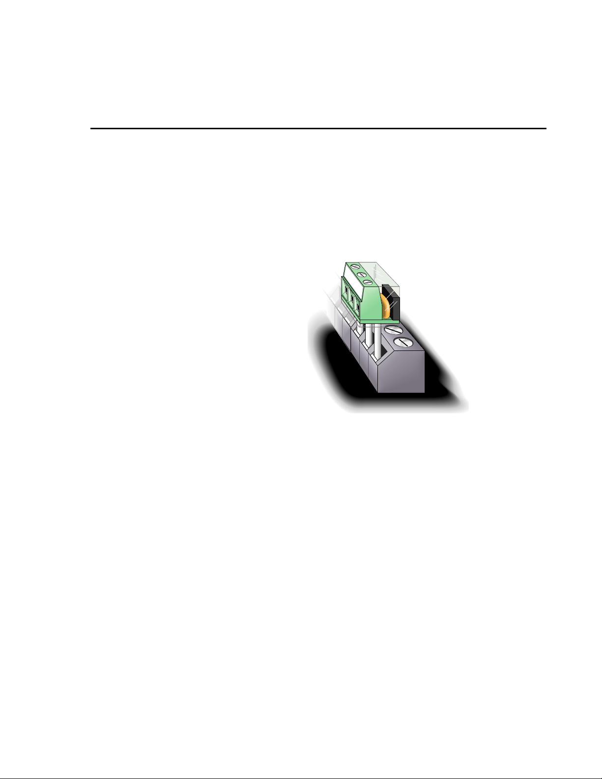
1-1. Terminal Input Module ...........................................................................1
2-1. Circuit Schematic....................................................................................2
3-1. Wiring for Example Programs ................................................................2
3-1. 4WPB100/4WPB1K Connections to Campbell Scientific Dataloggers..3
4-1. Excitation Voltage for 100 Ohm PRT in 4WPB100 Based on
Maximum Temperature and Input Voltage Range...............................3
4-2. Excitation Voltage for 1000 Ohm PRT in 4WPB1000 Based on
Maximum Temperature and Input Voltage Range...............................4
i
Page 4

This is a blank page.
Page 5
4WPB100, 4WPB1K PRT Bridge Terminal Input Modules
1. Function
Terminal input modules connect directly to the datalogger's input terminals to
provide completion resistors for resistive bridge measurements, voltage
dividers, and precision current shunts. The 4WPB100 and 4WPB1K are used
to provide completion resistors for 4 wire half bridge measurements of 100
Ohm and 1 killohm Platinum Resistance Thermometer (PRT), respectively.
H
L
G
H
L
AG
H
L
AG
2. Specifications
FIGURE 1-1. Terminal Input Module
Current limiting 10 kOhm Resistor
Tolerance @ 25 °C ±5%
Power rating 0.25 W
Completion Resistor
Tolerance @ 25 °C ±0.01%
Temperature coefficient
0-60 °C
-55-125 °C
Power rating 0.25 W
4 ppm/°C
8 ppm/°C
1
Page 6

4WPB100, 4WPB1K PRT Bridge Terminal Input Modules
Vx
HI
LO
HI
LO
GND
FIGURE 2-1. Circuit Schematic
3. Wiring
The Terminal input module is connected to the appropriate channel. The
dashed lines in Figure 2-1 indicate the sensor wiring. When making 4 wire
half bridge measurements, the 4WPB is connected to a differential channel and
the sense leads from the PRT to the next differential channel. The black
excitation wire is connected to the excitation channel. In th e following
examples the 4WPB is connected to differential channel 1 and the PRT to
differential channel 2; the excitation wire is connected to excitation channel 1
(Figure 3-1).
10k
0.01%
5%
Rf
H
Rf = 100 , 1k
L
Rs
GND
Datalogger
Ex1
4WPB100
1H
L
1L
AG or
G
2H
2L
FIGURE 3-1. Wiring for Example Programs
PRT
2
Page 7

4WPB100, 4WPB1K PRT Bridge Terminal Input Modules
TABLE 3-1. 4WPB100/4WPB1K Connections to
Campbell Scientific Dataloggers
Function
Excitation Black Wire E1 EX1 Excitation 1
V1 High H 1H 1H 1H
V1 Low L 1L 1L 1L
Ground G AG
Label/Lead
4. Programming Examples
The following examples simply show the two instructions necessary to 1)
make the measurement and 2) calculate the temperature. The result of the 4
wire half bridge measurement as shown is Rs/Ro, the input required for the
PRT algorithm to calculate temperature. Note that “Full Bridge” is shown as
the name for measurement Instruction 9 (used with CR10(X), 21X, and CR7).
When Instruction 9 is used with the first measurement range not set to the
maximum input range, it becomes a four wire half bridge measurement.
All the examples are for a 100 Ohm PRT in the 4WPB100. The excitation
voltages used were chosen with the assumption that the temperature would not
exceed 50 °C. Tables 4-1 and 4-2 list excitation voltage as a function of
maximum temperature and the input voltage ranges used with the different
dataloggers. Calculation of optimum excitation voltage is discussed in Section
5.1.
CR10X,
CR510
CR23X, CR1000,
CR800, CR850,
CR3000
21X, CR7,
CR9000X
TABLE 4-1. Excitation Voltage for 100 Ohm PRT in
4WPB100 Based on Maximum Temperature and Input
Voltage Range
Excitation Voltage, mV
Max.
Temp
°C
50 119.4 2035 4070
100 138.5 1758 3516
150 157.31 1551 3101
200 175.84 1390 2780
250 194.07 1262 2523
300 212.02 1157 2314
350 229.67 1070 2140
400 247.04 997 1993
450 264.11 934 1867
500 280.9 879 1759
550 297.39 832 1664
600 313.59 790 1581
PRT
Resistance
Ohms
±25 mV Input
Range, CR10(X),
CR800, CR850,
CR1000
±50 mV
Range, 21X,
CR7, CR3000,
CR9000X
3
Page 8

4WPB100, 4WPB1K PRT Bridge Terminal Input Modules
g
650 329.51 753 1507
700 345.13 720 1441
750 360.47 691 1382
800 375.51 664 1328
850 390.26 640 1280
TABLE 4-2. Excitation Voltage for 1000 Ohm PRT in
4WPB1000 Based on Maximum Temperature and Input Volta
Excitation Voltage, mV
Max.
Temp.
°C
PRT
Resist.
Ohms
±200 mV Input
Range
CR9000X
50 1194. 1959 2448 4897
100 1385. 1716 2145 4291
150 1573.1 1535 1919 3837
200 1758.4 1394 1743 3486
250 1940.7 1282 1603 3205
300 2120.2 1190 1488 2976
350 2296.7 1114 1393 2786
400 2470.4 1050 1313 2625
450 2641.1 995 1244 2488
500 2809. 948 1184 2369
550 2973.9 906 1133 2265
600 3135.9 870 1087 2174
650 3295.1 837 1047 2093
700 3451.3 808 1011 2021
750 3604.7 783 978 1956
800 3755.1 759 949 1898
850 3902.6 738 923 1845
Range
±250 mV Input
Range CR10(X),
CR1000, CR800,
CR850
e
±500 mV Input
Range 21X,
CR7, CR3000
4
Page 9

4WPB100, 4WPB1K PRT Bridge Terminal Input Modules
4.1 CR10(X)
01: Full Bridge w/mv Excit (P9)
1: 1 Reps
2: 23 ±25 mV 60 Hz Rejection Ex Range
3: 23 ±25 mV 60 Hz Rejection Br Range
4: 1 DIFF Channel
5: 1 Excite all reps w/Exchan 1
6: 2035 mV Excitation
7: 1 Loc [ Rs_Ro ]
8: 1.0 Mult
9: 0 Offset
02: Temperature RTD (P16)
1: 1 Reps
2: 1 R/Ro Loc [ Rs_Ro ]
3: 2 Loc [ Temp_C ]
4: 1 Mult
5: 0 Offset
4.2 21X
1: Full Bridge w/mv Excit (P9)
1: 1 Reps
2: 3 ± 50 mV Slow Ex Range
3: 3 ± 50 mV Slow Br Range
4: 1 DIFF Channel
5: 1 Excite all reps w/Exchan 1
6: 4070 mV Excitation
7: 1 Loc [ Rs_Ro ]
8: 1.0 Mult
9: 0.0 Offset
2: Temperature RTD (P16)
1: 1 Reps
2: 1 R/RO Loc [ Rs_Ro ]
3: 2 Loc [ Temp_C ]
4: 1.0 Mult
5: 0.0 Offset
5
Page 10

4WPB100, 4WPB1K PRT Bridge Terminal Input Modules
4.3 CR7
1: Full Bridge w/mv Excit (P9)
1: 1 Reps
2: 3 ± 15 mV Slow Range
3: 3 ± 15 mV Slow Range
4: 1 In Card
5: 1 DIFF Channel
6: 1 Ex Card
7: 1 Ex Channel
8: 1 Meas/Ex
9: 4070 mV Excitation
10: 1 Loc [ Rs_Ro ]
11: 1.0 Mult
12: 0.0 Offset
2: Temperature RTD (P16)
1: 1 Reps
2: 1 R/RO Loc [ Rs_Ro ]
3: 2 Loc [ Temp_C ]
4: 1.0 Mult
5: 0.0 Offset
4.4 CR9000X
'CR9000X Datalogger
Public Rs_Ro, Temp_F
DataTable (Temp_F,1,-1)
DataInterval (0,0,0,10)
Sample (1,Temp_F,FP2)
EndTable
BeginProg
Scan (1,mSec,0,0)
BrHalf4W (Rs_Ro,1,mV50,mV50,4,1,5,7,1,4070,True,True,30,40,1.0,0)
PRT (Temp_F,1,Rs_Ro,1.8,32)
CallTable Temp_F
NextScan
EndProg
6
Page 11

4WPB100, 4WPB1K PRT Bridge Terminal Input Modules
⋅
4.5 CR1000
'CR1000 Series Datalogger
Public Rs_R0, Temp_C
DataTable (Hourly,True,-1)
DataInterval (0,60,Min,0)
Average (1,Temp_C,IEEE4,0)
EndTable
BeginProg
Scan (1,Sec,0,0)
BrHalf4W (Rs_R0,1,mV25,mV25,1,Vx1,1,2035,True ,True ,0,250,1.0,0)
PRT (Temp_C,1,Rs_R0,1.0,0)
CallTable Hourly
NextScan
EndProg
5. PRT in 4 Wire Half Bridge
A 4 wire half bridge is the best choice for accuracy where the Platinum
Resistance Thermometer (PRT) is separated from other bridge completion
resistors by a lead length having more than a few thousandths of an Ohm
resistance. Four wires to the sensor allow one set of wires to carry the
excitation current and a separate set of sense wires that allow the voltage
across the PRT to be measured without the effect of any voltage drop in the
excitation leads.
Figure 2-1 shows the circuit used to measure the PRT. The 10 kOhm resistor
allows the use of a high excitation voltage and low voltage ranges on the
measurements. This insures that noise in the excitation does not have an effect
on signal noise and that self heating of the PRT due to excitation is kept to a
minimum. Because the fixed resistor (R
approximately the same resistance, the differential measurement of the voltage
drop across the PRT can be made on the same range as the differential
measurement of the voltage drop across R
The result of the four wire half bridge Instruction is:
V
2
V
1
the voltage drop is equal to the current (I), times the resistance thus:
) and the PRT (Rs) have
f
.
f
VVIR
2
1
=
IRRR
⋅
s
s
=
f
f
7
Page 12

4WPB100, 4WPB1K PRT Bridge Terminal Input Modules
The RTD Instruction (16) computes the temperature (°C) for a DIN 43760
standard PRT from the ratio of the PRT resistance at the temperature being
measured (R
) to its resistance at 0°C (R0). Thus, a multiplier of Rf/R0 is used
s
with the 4 wire half bridge instruction to obtain the desired intermediate, R
= (R
x Rf/Ro). If Rf and R0 are equal, the multiplier is 1.
s/Rf
The fixed resistor must be thermally stable. The 4 ppm/°C temperature
coefficient would result in a maximum error of 0.05 °C at 60 °C. The 8
ppm/°C temperature coefficient would result in a maximum error of 0.33 °C at
125 °C. Because the measurement is ratiometric (R
the absolute values of either R
not affect the result.
5.1 Excitation Voltage
The best resolution is obtained when the excitation voltage is large enough to
cause the signal voltage to fill the measurement voltage range. The voltage
drop across the PRT is equal to the current, I, multiplied by the resistance of
the PRT, R
measure a temperature in the range of -10 to 40°C, the maximum voltage drop
will be at 40°C when R
voltage that can be used when the measurement range is ±25 mV, we assume
equal to 25 mV and use Ohm's Law to solve for the resulting current, I.
V
2
, and is greatest when Rs is greatest. For example, if it is desired to
s
=115.54 Ohms. To find the maximum excitation
s
s/R0
) and does not rely on
s/Rf
or Rf, the properties of the 10 kOhm resistor do
s
V
is equal to I multiplied by the total resistance:
x
If the actual resistances were the nominal values, the 25 mV range would not
be exceeded with V
resistances, it is decided to set V
resistor is 5% low, then R
V to keep V
5.2 Calibrating a PRT
The greatest source of error in a PRT is likely to be that the resistance at 0 °C
deviates from the nominal value. Calibrating the PRT in an ice bath can
correct this offset and any offset in the fixed resistor in the Terminal Input
Module.
The result of the 4 wire half bridge is:
VVIR
⋅
2
=
IRRR
⋅
1
I = 25 mV/R
= 2.2 V. To allow for the tolerances in the actual
x
less than 25 mV).
s
s
s
=
f
f
= 25 mV/115.54 Ohms
s
= 0.216 mA
= I(R1+Rs+Rf) = 2.21 V
V
x
equal to 2.1 volts (e.g., if the 10 kOhm
x
/(R1+Rs+Rf)=115.54/9715.54, and Vx must be 2.102
s
8
Page 13

4WPB100, 4WPB1K PRT Bridge Terminal Input Modules
With the PRT at 0 °C, R
reciprocal of the multiplier required to calculate temperature, R
making a measurement with the PRT in an ice bath, errors in both R
. Thus, the above result becomes Ro/Rf, the
s=Ro
f/R0
. By
and Ro.
s
can be accounted for.
To perform the calibration, connect the PRT to the datalogger and program the
datalogger to measure the PRT with the 4 wire half bridge as shown in the
example section (multiplier = 1). Place the PRT in an ice bath (@ 0°C;
). Read the result of the bridge measurement. The reading is Rs/Rf,
R
s=R0
which is equal to R
since Rs=Ro. The correct value of the multiplier, Rf/R0,
o/Rf
is the reciprocal of this reading. For example, if the initial reading is 0.9890,
the correct multiplier is: R
= 1/0.9890 = 1.0111.
f/R0
9
Page 14

4WPB100, 4WPB1K PRT Bridge Terminal Input Modules
This is a blank page.
10
Page 15

This is a blank page.
Page 16

Campbell Scientific Companies
Campbell Scientific, Inc. (CSI)
815 West 1800 North
Logan, Utah 84321
UNITED STATES
www.campbellsci.com
info@campbellsci.com
Campbell Scientific Africa Pty. Ltd. (CSAf)
PO Box 2450
Somerset West 7129
SOUTH AFRICA
www.csafrica.co.za
cleroux@csafrica.co.za
Campbell Scientific Australia Pty. Ltd. (CSA)
PO Box 444
Thuringowa Central
QLD 4812 AUSTRALIA
www.campbellsci.com.au
info@campbellsci.com.au
Campbell Scientific do Brazil Ltda. (CSB)
Rua Luisa Crapsi Orsi, 15 Butantã
CEP: 005543-000 São Paulo SP BRAZIL
www.campbellsci.com.br
suporte@campbellsci.com.br
Campbell Scientific Canada Corp. (CSC)
11564 - 149th Street NW
Edmonton, Alberta T5M 1W7
CANADA
www.campbellsci.ca
dataloggers@campbellsci.ca
Campbell Scientific Ltd. (CSL)
Campbell Park
80 Hathern Road
Shepshed, Loughborough LE12 9GX
UNITED KINGDOM
www.campbellsci.co.uk
sales@campbellsci.co.uk
Campbell Scientific Ltd. (France)
Miniparc du Verger - Bat. H
1, rue de Terre Neuve - Les Ulis
91967 COURTABOEUF CEDEX
FRANCE
www.campbellsci.fr
campbell.scientific@wanadoo.fr
Campbell Scientific Spain, S. L.
Psg. Font 14, local 8
08013 Barcelona
SPAIN
www.campbellsci.es
info@campbellsci.es
Please visit www.campbellsci.com to obtain contact information for your local US or International representative.
 Loading...