

Page 1

4WFB120, 4WFB350, 4WFB1K
4 Wire Full Bridge Terminal
Input Modules
Revision: 5/07
Copyright © 1996-2007
Campbell Scientific, Inc.
Page 2

Warranty and Assistance
The 4WFB120, 4WFB350, 4WFB1K 4 WIRE FULL BRIDGE
TERMINAL INPUT MODULES are warranted by CAMPBELL
SCIENTIFIC, INC. to be free from defects in materials and workmanship
under normal use and service for twelve (12) months from date of shipment
unless specified otherwise. Batteries have no warranty. CAMPBELL
SCIENTIFIC, INC.'s obligation under this warranty is limited to repairing or
replacing (at CAMPBELL SCIENTIFIC, INC.'s option) defective products.
The customer shall assume all costs of removing, reinstalling, and shipping
defective products to CAMPBELL SCIENTIFIC, INC. CAMPBELL
SCIENTIFIC, INC. will return such products by surface carrier prepaid. This
warranty shall not apply to any CAMPBELL SCIENTIFIC, INC. products
which have been subjected to modification, misuse, neglect, accidents of
nature, or shipping damage. This warranty is in lieu of all other warranties,
expressed or implied, including warranties of merchantability or fitness for a
particular purpose. CAMPBELL SCIENTIFIC, INC. is not liable for special,
indirect, incidental, or consequential damages.
Products may not be returned without prior authorization. The following
act information is for US and International customers residing in countries
cont
served by Campbell Scientific, Inc. directly. Affiliate companies handle
repairs for customers within their territories. Please visit
www.campbellsci.com to determine which Campbell Scientific company
serves your country. To obtain a Returned Materials Authorization (RMA),
contact CAMPBELL SCIENTIFIC, INC., phone (435) 753-2342. After an
applications engineer determines the nature of the problem, an RMA number
will be issued. Please write this number clearly on the outside of the shipping
container. CAMPBELL SCIENTIFIC's shipping address is:
CAMPBELL SCIENTIFIC, INC.
RMA#_____
815 W
Logan, Ut
CAMPBELL SCIENTIFIC, INC. does not accept collect calls.
est 1800 North
ah 84321-1784
Page 3

4WFB120, 4WFB350, 4WFB1K
Table of Contents
PDF viewers note: These page numbers refer to the printed version of this document. Use
the Adobe Acrobat® bookmarks tab for links to specific sections.
1. Function........................................................................1
2. Specifications ..............................................................1
3. Measurement Concepts..............................................2
4. Wiring............................................................................3
5. Program Examples......................................................3
5.1 Edlog.........................................................................................................4
5.1.1 CR10(X)..........................................................................................4
5.1.2 21X .................................................................................................7
5.1.3 CR7...............................................................................................10
5.2 CRBasic..................................................................................................13
5.2.1 CR9000(X)....................................................................................14
6. Calculation of Strain..................................................15
Figures
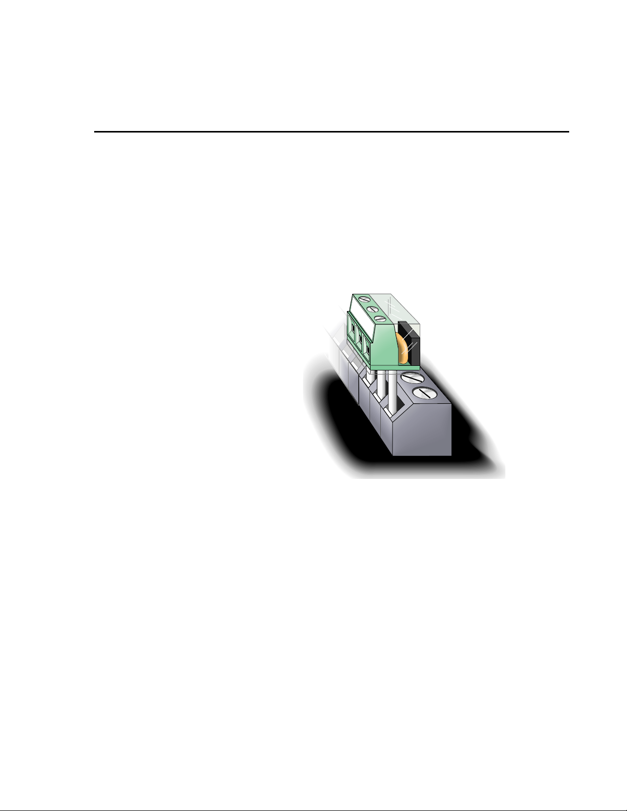
1-1 Terminal Input Module ............................................................................1
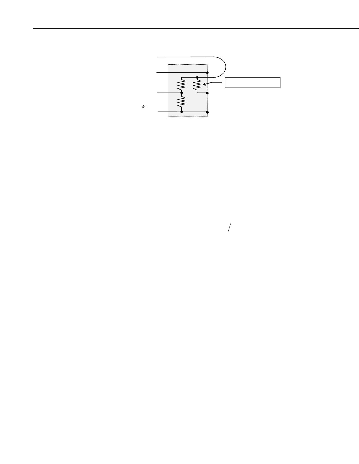
2-1 Schematic.................................................................................................2
4-1 Wiring for Example Programs .................................................................3
6-1 Strain Gage in Full Bridge......................................................................15
Table
5-1 Input Locations Used in CR10(X), 21X, and CR7 Examples..................4
i
Page 4

This is a blank page.
Page 5
4WFB120, 4WFB350, 4WFB1K 4 Wire Full Bridge Terminal Input Modules
1. Function
Terminal input modules connect directly to the datalogger's input terminals to
provide completion resistors for resistive bridge measurements, voltage
dividers, and precision current shunts. The 4WFB120, 4WFB350, and
4WFB1K complete a full bridge for a strain gage or other sensor that acts as a
single variable resistor. The difference between the three models is in the
resistor that matches the nominal resistance of a 120 ohm, 350 ohm, or 1000
ohm quarter bridge strain gage.
H
L
G
H
L
AG
2. Specifications
2:1 Resistive Divider
Resistors
Ratio Tolerance @ 25 °C
Ratio Temperature
coefficient
Power rating 0.25 W
Completion Resistor: 120, 350, or 1000 Ω
Tolerance @ 25 °C
Temperature coefficient
0-60 °C
-55-125 °C
Power rating 0.25 W
H
L
AG
FIGURE 1-1. Terminal Input Module
1 kΩ/1 kΩ
±0.02%
2 ppm/°C
±0.01%
4 ppm/°C
8 ppm/°C
1
Page 6
4WFB120, 4WFB350, 4WFB1K 4 Wire Full Bridge Terminal Input Modules
ε
µ
=
∆
∆
µ
x
⋅
x
Vx
H
L
or AG
3. Measurement Concepts
Measuring strain is measuring a change in length. Specifically, the unit strain
()
is the change in length divided by the unstrained length
Strain is typically reported in microstrain
length by one millionth of the length.
A metal foil strain gage is a resistive element that changes resistance as it is
stretched or compressed. The strain gage is bonded to the object in which
strain is measured. The gage factor,
resistance for change in strain:
factor of 2 means that if the length changes by one micrometer per meter of
)
(1
ε
length
resistance.
, the resistance will change by two micro-ohms per ohm of
H
1kΩ
1kΩ
FIGURE 2-1. Schematic
H
L
G
()
GF , is the ratio of the relative change in
GF R R l l
120Ω, 350Ω, or 1kΩ
ε
=∆ll/
()
ε
; a microstrain is a change in
//
. For example, a gage
.
Because the actual change in resistance is so small, a full bridge configuration
is used to give the maximum resolution. A "quarter bridge" strain gage is so
named because the strain gage becomes one of the four resistors that make up a
full bridge. The 4WFBxxx module provides the other three resistors (Figure 4-
1). Quarter bridge strain gages are available in nominal unstrained resistances
of 120, 350, and 1000 ohms. The 4WFB model must match the resistance of
the gage (e.g., the 4WFB120 is used with a 120 ohm strain gage).
The resistance of an installed gage will differ from the nominal value. A zero
measurement can be made with the gage installed. This zero measurement can
be incorporated into the datalogger program; subsequent measurements can
report strain relative to the zero.
Strain is calculated in terms of the result of the full bridge measurement. This
result is the measured bridge output voltage divided by the bridge excitation
VV
/
voltage
millivolts output per volt of excitation,
measurement,
measurements. Strain is calculated from the change in the bridge
measurement,
outex
. (The actual result of the full bridge instruction is the
1000
VV
/
is stored and used to calculate future strain
0
out e
1000⋅VV
/
out e
) The result of the zero
2
Page 7
r
x
x
=
−
4. Wiring
4WFB120, 4WFB350, 4WFB1K 4 Wire Full Bridge Terminal Input Modules
VVV VV
(/)( /0)
out e
ε
=
GF V
out e
V
r
−412
()
r
: 3.1.
3.2.
The calculations are covered in more detail in section 6.
Datalogger
Vx
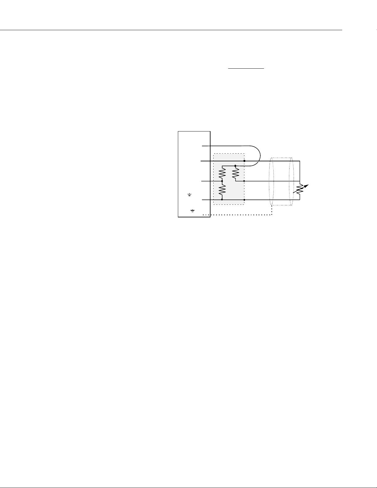
Figure 4-1 illustrates the wiring of the strain gage to the 4WFB module and the
wiring of the module to the datalogger. It is important that the gage be wired
as shown with the wire from H connected at the gage, and that the leads to the
L and G terminals be the same length, diameter, and wire type. With this
configuration, changes in wire resistance due to temperature occur equally in
both arms of the bridge with negligible effect on the output from the bridge.
5. Program Examples
The following examples for the CR10(X), 21X, CR7, and CR9000(X) all have
a subroutine that measures the unstrained "zero" output of the strain gage. The
examples calculate strain using equation 3.2 for a strain gage with a GF=2.
These are just examples. Besides adding additional measurement instructions,
the programs will probably need to have the scan and d ata storage intervals
altered for actual applications. The instructions in the subroutine will also
need to be modified for the actual gage factor.
H
H
L
G
or AG
or G
H
L
Shield
FIGURE 4-1. Wiring for Example Programs
This zeroing subroutine is called automatically when the progr am is first
executed. The user can call the subroutine by setting Flag 1 low using the
datalogger support software or the *6 mode with the keyboard display. The
"zero" reading is then used during normal measurements for the strain
calculations.
3
Page 8

4WFB120, 4WFB350, 4WFB1K 4 Wire Full Bridge Terminal Input Modules
5.1 Edlog
Dataloggers that use Edlog include CR510, CR10(X), 21X, and CR7. The
Edlog instruction that measures strain gages is Instruction 6 – Full Bridge.
The Input Locations assignments used in CR10(X), 21X, and CR7 Examples
are listed in Table 5-1.
TABLE 5-1. Input
Locations Used in
CR10(X), 21X, and CR7
Examples
Addr Name
1 mVperV
2 mVperV_0
3 Vr
4 uStrain
5 Count
6 GF
7 _4e6
8 Mult
9 1_2Vr
10 Vr_1_2Vr
5.1.1 CR10(X)
;{CR10X}
;
*Table 1 Program
01: 1 Execution Interval (seconds)
;Other measurements could be inserted here or before the Output section
1: If Flag/Port (P91) ;On the first execution (Flag 1 is low)
1: 21 Do if Flag 1 is Low ;or when user sets Flag 1 low
2: 1 Call Subroutine 1 ;call the zeroing subroutine
2: Full Bridge (P6) ;Measure the strain gage
1: 1 Reps
2: 22 ± 7.5 mV 60 Hz Rejection Range
3: 1 DIFF Channel
4: 1 Excite all reps w/Exchan 1
5: 2500 mV Excitation
6: 1 Loc [ mVperV ]
7: 1 Mult
8: 0 Offset
4
Page 9

4WFB120, 4WFB350, 4WFB1K 4 Wire Full Bridge Terminal Input Modules
3: X-Y (P35) ;Subtract zero reading from the
1: 1 X Loc [ mVperV ] ;measurement
2: 2 Y Loc [ mVperV_0 ]
3: 3 Z Loc [ Vr ]
4: X*F (P37) ;Change Vr from mV/V to V/V
1: 3 Loc [ Vr ]
2: 0.001
3: 3 Loc [ Vr ]
;The following instructions calculate microstrain
5: Z=X*F (P37)
1: 3 X Loc [ Vr ]
2: -2 F
3: 9 Z Loc [ 1_2Vr ]
6: Z=Z+1 (P32)
1: 9 Z Loc [ 1_2Vr ]
7: Z=X/Y (P38)
1: 3 X Loc [ Vr ]
2: 9 Y Loc [ 1_2Vr ]
3: 10 Loc [ Vr_1_2Vr ]
8: Z=X*Y (P36)
1: 10 X Loc [ Vr_1_2Vr ]
2: 8 Y Loc [ Mult ]
3: 4 Z Loc [ uStrain ]
;Output Section
;This example outputs an average of the 1 second readings
;once per minute.
09: If time is (P92)
1: 0 Minutes (Seconds --) into a
2: 1 Interval (same units as above)
3: 10 Set Output Flag High
10: Set Active Storage Area (P80)
1: 1 Final Storage Area 1
2: 1 Array ID ;Set Array ID = 1 for measurement data
11: Real Time (P77)
1: 1110 Year,Day,Hour/Minute
12: Average (P71)
1: 1 Reps
2: 4 Loc [ uStrain ]
*Table 2 Program
2: 0.0000 Execution Interval (seconds)
5
Page 10

4WFB120, 4WFB350, 4WFB1K 4 Wire Full Bridge Terminal Input Modules
*Table 3 Subroutines
1: Beginning of Subroutine (P85) ;Subroutine to measure "zero"
1: 1 Subroutine 1
2: Do (P86) ;This prevents calling subroutine
1: 11 Set Flag 1 High ;until user sets flag 1 low again.
3: Z=F (P30) ;Set counter use for average to 0
1: 0 F
2: 0 Exponent of 10
3: 5 Z Loc [ Count ]
4: Z=F (P30) ;load 4 million (4*uS/S) into input location
1: 4 F
2: 6 Exponent of 10
3: 7 Z Loc [ _4e6 ]
5: Z=F (P30) ;Load Gage Factor into input location
1: 2 F ;Enter the actual Gage Factor here
2: 0 Exponent of 10
3: 6 Z Loc [ GF ]
6: Z=X/Y (P38) ;calculate multiplier to use with strain
1: 7 X Loc [ _4e6 ] ;calculation
2: 6 Y Loc [ GF ]
3: 8 Z Loc [ Mult ]
7: Beginning of Loop (P87) ;Loop through 5 times to obtain average
1: 0 Delay ;zero reading
2: 5 Loop Count
8: Z=Z+1 (P32) ;Increment Counter used to determine
1: 5 Z Loc [ Count ] ;when to output
9: Full Bridge (P6) ;Measure Strain Gage
1: 1 Reps
2: 22 ± 7.5 mV 60 Hz Rejection Range
3: 1 DIFF Channel
4: 1 Excite all reps w/Exchan 1
5: 2500 mV Excitation
6: 1 Loc [ mVperV ]
7: 1 Mult
8: 0 Offset
10: IF (X<=>F) (P89) ;Check for last pass through loop
1: 5 X Loc [ Count ] ;to set output flag
2: 3 >=
3: 5 F
4: 10 Set Output Flag High
6
Page 11

4WFB120, 4WFB350, 4WFB1K 4 Wire Full Bridge Terminal Input Modules
11: Set Active Storage Area (P80) ;Direct averaged "zero" reading
1: 3 Input Storage Area ;to input storage
2: 2 Array ID or Loc [ mVperV_0 ]
12: Average (P71)
1: 1 Reps
2: 1 Loc [ mVperV ]
13: If Flag/Port (P91) ;When average is calculated,
1: 10 Do if Output Flag is High (Flag 0) ;also send it to Final Storage
2: 10 Set Output Flag High
14: Set Active Storage Area (P80) ;Direct Output to Final Storage
1: 1 Final Storage Area 1
2: 11 Array ID ;set Array ID = 11 for zero data
15: Real Time (P77)
1: 110 Day,Hour/Minute
16: Sample (P70)
1: 1 Reps
2: 2 Loc [ mVperV_0 ]
17: End (P95)
18: End (P95)
End Program
5.1.2 21X
;{21X}
*Table 1 Program
01: 1 Execution Interval (seconds)
;Other measurements could be inserted here or before the Output section
1: If Flag/Port (P91) ;On the first execution (Flag 1 is low)
1: 21 Do if Flag 1 is Low ;or when user sets Flag 1 low
2: 1 Call Subroutine 1 ;call the zeroing subroutine
2: Full Bridge (P6) ;Measure the strain gage
1: 1 Reps
2: 2 ± 15 mV Slow Range
3: 1 DIFF Channel
4: 1 Excite all reps w/Exchan 1
5: 5000 mV Excitation
6: 1 Loc [ mVperV ]
7: 1 Mult
8: 0 Offset
7
Page 12

4WFB120, 4WFB350, 4WFB1K 4 Wire Full Bridge Terminal Input Modules
3: Z=X-Y (P35) ;Subtract zero reading from the
1: 1 X Loc [ mVperV ] ;measurement
2: 2 Y Loc [ mVperV_0 ]
3: 3 Z Loc [ Vr ]
4: Z=X*F (P37) ;Change Vr from mV/V to V/V
1: 3 X Loc [ Vr ]
2: 0.001 F
3: 3 Z Loc [ Vr ]
;The following instructions calculate microstrain
5: Z=X*F (P37)
1: 3 X Loc [ Vr ]
2: -2 F
3: 9 Z Loc [ 1_2Vr ]
6: Z=Z+1 (P32)
1: 9 Z Loc [ 1_2Vr ]
7: Z=X/Y (P38)
1: 3 X Loc [ Vr ]
2: 9 Y Loc [ 1_2Vr ]
3: 10 Z Loc [ Vr_1_2Vr ]
8: Z=X*Y (P36)
1: 10 X Loc [ Vr_1_2Vr ]
2: 8 Y Loc [ Mult ]
3: 4 Z Loc [ uStrain ]
;Output Section
;This example outputs an average of the 1 second readings
;once per minute.
9: If time is (P92)
1: 0 Minutes (Seconds --) into a
2: 1 Interval (same units as above)
3: 10 Set Output Flag High
10: Set Active Storage Area (P80)
1: 1 Final Storage Area 1
2: 1 Array ID ;Set Array ID = 1 for measurement data
11: Real Time (P77)
1: 1110 Year,Day,Hour/Minute
12: Average (P71)
1: 1 Reps
2: 4 Loc [ uStrain ]
*Table 2 Program
01: 0.0000 Execution Interval (seconds)
8
Page 13

4WFB120, 4WFB350, 4WFB1K 4 Wire Full Bridge Terminal Input Modules
*Table 3 Subroutines
1: Beginning of Subroutine (P85) ;Subroutine to measure "zero"
1: 1 Subroutine 1
2: Do (P86) ;This prevents calling subroutine
1: 11 Set Flag 1 High ;until user sets flag 1 low again.
3: Z=F (P30) ;Set counter use for average to 0
1: 0 F
2: 5 Z Loc [ count ]
4: Z=F (P30) ;load 4000 into
1: 4000 F ;input location
2: 7 Z Loc [ 4e6 ]
5: Z=X*F (P37) ;Multiply by 1000 to get (4*uS/S)
1: 7 X Loc [ 4e6 ]
2: 1000 F
3: 7 Z Loc [ 4e6 ]
6: Z=F (P30) ;Load Gage Factor into input location
1: 2 F ;Enter the actual Gage Factor here
2: 6 Z Loc [ GF ]
7: Z=X/Y (P38) ;calculate multiplier to use with strain
1: 7 X Loc [ 4e6 ] ;calculation
2: 6 Y Loc [ GF ]
3: 8 Z Loc [ Mult ]
8: Beginning of Loop (P87) ;Loop through 5 times to obtain average
1: 0 Delay ;zero reading
2: 5 Loop Count
9: Z=Z+1 (P32) ;Increment Counter used to determine
1: 5 Z Loc [ count ] ;when to output
10: Full Bridge (P6) ;Measure Strain Gage
1: 1 Reps
2: 2 ± 15 mV Slow Range
3: 1 DIFF Channel
4: 1 Excite all reps w/Exchan 1
5: 5000 mV Excitation
6: 1 Loc [ mVperV ]
7: 1 Mult
8: 0 Offset
11: IF (X<=>F) (P89) ;Check for last pass through loop
1: 5 X Loc [ count ] ;to set output flag
2: 3 >=
3: 5 F
4: 10 Set Output Flag High
9
Page 14

4WFB120, 4WFB350, 4WFB1K 4 Wire Full Bridge Terminal Input Modules
12: Set Active Storage Area (P80) ;Direct averaged "zero" reading
1: 3 Input Storage ;to input storage
2: 2 Array ID or Loc [ mVperV_0 ]
13: Average (P71)
1: 1 Reps
2: 1 Loc [ mVperV ]
14: If Flag/Port (P91) ;When average is calculated,
1: 10 Do if Output Flag is High (Flag 0) ;also send it to Final Storage
2: 10 Set Output Flag High
15: Set Active Storage Area (P80) ;Direct Output to Final Storage
1: 1 Final Storage
2: 11 Array ID ;set Array ID = 11 for zero data
16: Real Time (P77)
1: 110 Day,Hour/Minute
17: Sample (P70)
1: 1 Reps
2: 2 Loc [ mVperV_0 ]
18: End (P95)
19: End (P95)
End Program
5.1.3 CR7
;{CR7}
*Table 1 Program
01: 1.0000 Execution Interval (seconds)
;Other measurements could be inserted here or before the Output section
1: If Flag/Port (P91) ;On the first execution (Flag 1 is low)
1: 21 Do if Flag 1 is Low ;or when user sets Flag 1 low
2: 1 Call Subroutine 1 ;call the zeroing subroutine
2: Full Bridge (P6) ;Measure the strain gage
1: 1 Reps
2: 3 ±15 mV Slow Range
3: 1 In Card
4: 1 DIFF Channel
5: 1 Ex Card
6: 1 Ex Channel
7: 1 Meas/Ex
8: 5000 mV Excitation
9: 1 Loc [ mVperV ]
10: 1 Mult
11: 0 Offset
10
Page 15

4WFB120, 4WFB350, 4WFB1K 4 Wire Full Bridge Terminal Input Modules
3: Z=X-Y (P35) ;Subtract zero reading from the
1: 1 X Loc [ mVperV ] ;measurement
2: 2 Y Loc [ mVperV_0 ]
3: 3 Z LOC [ Vr ]
4: Z=X*F (P37) ;Change Vr from mV/V to V/V
1: 3 X Loc [ Vr ]
2: 0.001 F
3: 3 Z Loc [ Vr ]
;The following instructions calculate microstrain
5: Z=X*F (P37)
1: 3 X Loc [ Vr ]
2: -2 F
3: 9 Z LOC [ 1_2Vr ]
6: Z=Z+1 (P32)
1: 9 Z LOC [ 1_2Vr ]
7: Z=X/Y (P38)
1: 3 X Loc [ Vr ]
2: 9 Y Loc [ 1_2Vr ]
3: 10 Z LOC [ Vr_1_2Vr ]
8: Z=X*Y (P36)
1: 10 X Loc [ Vr_1_2Vr ]
2: 8 Y Loc [ Mult ]
3: 4 Z LOC [ uStrain ]
;Output Section
;This example outputs an average of the 1 second readings
;once per minute.
9: If time is (P92)
1: 0 Minutes (Seconds --) into a
2: 1 Interval (same units as above)
3: 10 Set Output Flag High
10: Set Active Storage Area (P80)
1: 1 Final Storage Area 1
2: 1 Array ID ;Set Array ID = 1 for measurement data
11: Real Time (P77)
1: 1110 Year,Day,Hour/Minute
12: Average (P71)
1: 1 Reps
2: 4 Loc [ uStrain ]
11
Page 16

4WFB120, 4WFB350, 4WFB1K 4 Wire Full Bridge Terminal Input Modules
*Table 2 Program
01: 0.0000 Execution Interval (seconds)
*Table 3 Subroutines
1: Beginning of Subroutine (P85) ;Subroutine to measure "zero"
1: 1 Subroutine 1
2: Do (P86) ;This prevents calling subroutine
1: 11 Set Flag 1 High ;until user sets flag 1 low again.
3: Z=F (P30) ;Set counter use for average to 0
1: 0 F
2: 5 Z LOC [ Count ]
4: Z=F (P30) ;load 4000 into
1: 4000 F ;input location
2: 7 Z LOC [ 4e6 ]
5: Z=X*F (P37) ;Multiply by 1000 to get (4*uS/S)
1: 7 X Loc [ 4e6 ]
2: 1000 F
3: 7 Z LOC [ 4e6 ]
6: Z=F (P30) ;Load Gage Factor into input location
1: 2 F ;Enter the actual Gage Factor here
2: 6 Z LOC [ GF ]
7: Z=X/Y (P38) ;calculate multiplier to use with strain
1: 7 X Loc [ 4e6 ] ;calculation
2: 6 Y Loc [ GF ]
3: 8 Z LOC [ Mult ]
8: Beginning of Loop (P87) ;Loop through 5 times to obtain average
1: 0 Delay ;zero reading
2: 5 Loop Count
9: Z=Z+1 (P32) ;Increment Counter used to determine
1: 5 Z Loc [ Count ] ;when to output
10: Full Bridge (P6) ;Measure Strain Gage
1: 1 Reps
2: 3 ± 15 mV Slow Range
3: 1 In Card
4: 1 DIFF Channel
5: 1 Ex Card
6: 1 Ex Channel
7: 1 Meas/Ex
8: 5000 mV Excitation
9: 1 Loc [ mVperV ]
10: 1 Mult
11: 0 Offset
12
Page 17

4WFB120, 4WFB350, 4WFB1K 4 Wire Full Bridge Terminal Input Modules
11: IF (X<=>F) (P89) ;Check for last pass through loop
1: 5 X Loc [ Count ] ;to set output flag
2: 3 >=
3: 5 F
4: 10 Set Output Flag High
12: Set Active Storage Area (P80) ;Direct averaged "zero" reading
1: 3 Input Storage ;to input storage
2: 2 Array ID or Loc [ mVperV_0 ]
13: Average (P71)
1: 1 Reps
2: 1 Loc [ mVperV ]
14: If Flag/Port (P91) ;When average is calculated,
1: 10 Do if Output Flag is High (Flag 0) ;also send it to Final Storage
2: 10 Set Output Flag High
15: Set Active Storage Area (P80) ;Direct Output to Final Storage
1: 1 Final Storage
2: 11 Array ID ;set Array ID = 11 for zero data
16: Real Time (P77)
1: 110 Day,Hour/Minute
17: Sample (P70)
1: 1 Reps
2: 2 Loc [ mVperV_0 ]
18: End (P95)
19: End (P95)
End Program
5.2 CRBasic
Dataloggers that use CRBasic include our CR800, CR850, CR1000, CR3000,
CR5000, and CR9000(X). CRBasic uses the StrainCalc Instruction for
calculating strain from the output of different full bridge configurations:
StrainCalc(Dest,Reps,Source,BrZero,BrConfig,GageFactor,PoissonRatio)
Source is the variable holding the current measurement, BrZero is the zero
measurement; this instruction uses the results of the full bridge measurement
instruction (multiplier=1, offset=0, mV/V) directly. The code for the Bridge
Configuration used with the 4WFB module is -1. Enter the actual gage factor
for GageFactor. Enter 0 for the Poisson ratio parameter which is not used with
this bridge configuration.
13
Page 18

4WFB120, 4WFB350, 4WFB1K 4 Wire Full Bridge Terminal Input Modules
5.2.1 CR9000(X)
This example program is slightly different in operation than the examples for
the other dataloggers. Data are only output to data table STRAINS when the
user sets Flag(1). Every measurement is output (rather than averages like in
the other examples) while Flag(1) is high.
' Program name: STRAIN.DLD
Public Count, ZStrain, StMeas, Strain, Flag(8) 'Declare all variables as public
'Data Table STRAINS samples every measurement when user Sets Flag(1) High
DataTable(STRAINS,Flag(1),-1)
DataInterval(0,0,0,100) 'Interval = Scan, 100 lapses
Sample (1,Strain,Ieee4)
EndTable
'DataTable ZERO_1 stores the "zero" measurements
DataTable(ZERO_1,Count>99,100) 'Trigger on Count 100
Average(1,ZStrain,IEEE4,0)
EndTable
'Subroutine to measure Zero, Called when user sets Flag(2)low
Sub Zero
Count = 0 'Reset Count
Scan(10,mSec,0,100) 'Scan 100 times
BrFull(ZStrain,1,mV50,5,1,6,7,1,5000,1,0,0,100,1,0)
Count = Count + 1 'Increment Counter used By DataTable
CallTable ZERO_1 'Zero_1 outputs on last scan (Count=100)
Next Scan
ZStrain = ZERO_1.ZStrain_Avg(1,1) 'Set ZStrain = averaged value
Flag(1) = True
End Sub
BeginProg
Scan(10,mSec,0,0) 'Scan 10(mSecs)
If Not Flag(2) Then Zero
BrFull(StMeas,1,mV50,5,1,6,7,1,5000,1,0,0,100,1,0)
StrainCalc(Strain,1,StMeas,ZStrain,-1,2,0)
CallTable STRAINS 'Strains outputs only when Flag(1)=True
Next Scan
EndProg
14
Page 19

4WFB120, 4WFB350, 4WFB1K 4 Wire Full Bridge Terminal Input Modules
⎛
⎞
R
∆
R
R
+
∆
6. Calculation of Strain
Vx
H
R1
L
R2
or AG
FIGURE 6-1. Strain Gage in Full Bridge
Figure 6-1 is the diagram of the strain gage in the full bridge configuration
provided by the terminal input module. The result of the datalogger's full
bridge measurement when a multiplier of 1 and an offset of 0 is used is the
measured bridge output in millivolts divided by the excitation in volts (1000
mV=1V):
Vout
1000 1000
⋅=⋅+−
Vin
The result is output in the units of millivolts output per volt o f excitation
because the output voltage is small relative to the excitation voltage; these
units allow the result to be a larger number easier for the datalogger to display
and store (see data format discussion in the datalogger manual). The output is
a ratio because: 1) the datalogger's ratiometric measurement technique allows
this ratio to be more accurate than the measurement of the output voltage
(errors in the excitation and measured output cancel). 2) This ratio can be used
directly in the calculation of strain.
H
H
R3
L
Rg
G
R
g
⎜
RRRRR
⎝
3
g
2
+
12
6.3.
⎟
⎠
When strain is calculated the direct ratio of the voltages (volts per volt not
millivolts per volt) will be used:
Vout
=
Vin
If the previous equation is taken as the result when the gage is unstrained, then
when the gage is strained it will change resistance by
the bridge output is:
Vout
Vin
=
strained
g
RRRRR
+
3
g
gg
RR RRRR
++
gg
3
−
12
∆
2
6.4.
+
R
. The equation for
g
2
−
12
6.5.
+
15
Page 20

4WFB120, 4WFB350, 4WFB1K 4 Wire Full Bridge Terminal Input Modules
r
+
∆
=
⋅
⋅
∆∆∆∆∆
(
∆
∆
Subtracting the unstrained (zero) result from the strained result gives
Vout
⎛
⎞
⎜
V
=
r
=
The terminal input module is selected so that
:
R
3
V
=
r
Solving for strain:
⎟
⎝
⎠
Vin
strained unstrained
RR R RR
()()
++ ⋅ +
gg g
33
++ ⋅ +
()()424
RR R RR
gg g gg
Vout
⎛
⎜
−
⎝
Vin
RR
⋅
∆
g
3
∆
RR
gg
42
42
⎞
⎟
⎠
=
+=
∆∆
RRV
ggr
+=
RV RV R
gr gr g
∆∆
RR
gg
=
RR RRRR
++
gggg
3
RR
RR
gg
2
+
RRRRRR
gggggg
)
R
g
−
∆
. Substituting R for
g3
=
+
3
+
2
V
:
6.6.
g
6.7.
∆
42
412
Strain is calculated by dividing equation 6.8 by the gage factor. The units are
converted to microstrain by multiplying by 10
µε
=−
RV R RV
RV R V
=
∆∆
gr g gr
=−
∆
gr g r
4
−
12VV
410
GF V
()
R
r
r
6
⋅
−
12
()
g
=
V
r
6.8.
R
g
6
uS/S.
6
10
=
GF R
r
⋅
R
g
6.9.
g
16
Page 21

This is a blank page.
Page 22

Campbell Scientific Companies
Campbell Scientific, Inc. (CSI)
815 West 1800 North
Logan, Utah 84321
UNITED STATES
www.campbellsci.com
info@campbellsci.com
Campbell Scientific Africa Pty. Ltd. (CSAf)
PO Box 2450
Somerset West 7129
SOUTH AFRICA
www.csafrica.co.za
cleroux@csafrica.co.za
Campbell Scientific Australia Pty. Ltd. (CSA)
PO Box 444
Thuringowa Central
QLD 4812 AUSTRALIA
www.campbellsci.com.au
info@campbellsci.com.au
Campbell Scientific do Brazil Ltda. (CSB)
Rua Luisa Crapsi Orsi, 15 Butantã
CEP: 005543-000 São Paulo SP BRAZIL
www.campbellsci.com.br
suporte@campbellsci.com.br
Campbell Scientific Canada Corp. (CSC)
11564 - 149th Street NW
Edmonton, Alberta T5M 1W7
CANADA
www.campbellsci.ca
dataloggers@campbellsci.ca
Campbell Scientific Ltd. (CSL)
Campbell Park
80 Hathern Road
Shepshed, Loughborough LE12 9GX
UNITED KINGDOM
www.campbellsci.co.uk
sales@campbellsci.co.uk
Campbell Scientific Ltd. (France)
Miniparc du Verger - Bat. H
1, rue de Terre Neuve - Les Ulis
91967 COURTABOEUF CEDEX
FRANCE
www.campbellsci.fr
campbell.scientific@wanadoo.fr
Campbell Scientific Spain, S. L.
Psg. Font 14, local 8
08013 Barcelona
SPAIN
www.campbellsci.es
info@campbellsci.es
Please visit www.campbellsci.com to obtain contact information for your local US or International representative.
 Loading...