

Page 1

Model 237 Leaf Wetness Sensor
Revision: 7/10
Copyright © 1988-2010
Campbell Scientific, Inc.
Page 2

Warranty and Assistance
The 237 LEAF WETNESS SENSOR is warranted by Campbell Scientific,
Inc. to be free from defects in materials and workmanship under normal use
and service for twelve (12) months from date of shipment unless specified
otherwise. Batteries have no warranty. Campbell Scientific, Inc.'s obligation
under this warranty is limited to repairing or replacing (at Campbell Scientific,
Inc.'s option) defective products. The customer shall assume all costs of
removing, reinstalling, and shipping defective products to Campbell Scientific,
Inc. Campbell Scientific, Inc. will return such products by surface carrier
prepaid. This warranty shall not apply to any Campbell Scientific, Inc.
products which have been subjected to modification, misuse, neglect, accidents
of nature, or shipping damage. This warranty is in lieu of all other warranties,
expressed or implied, including warranties of merchantability or fitness for a
particular purpose. Campbell Scientific, Inc. is not liable for special, indirect,
incidental, or consequential damages.
Products may not be returned without prior authorization. The following
contact information is for US and International customers residing in countries
served by Campbell Scientific, Inc. directly. Affiliate companies handle
repairs for customers within their territories. Please visit
www.campbellsci.com to determine which Campbell Scientific company
serves your country.
To obtain a Returned Materials Authorization (RMA), contact Campbell
Scientific, Inc., phone (435) 753-2342. After an applications engineer
determines the nature of the problem, an RMA number will be issued. Please
write this number clearly on the outside of the shipping container. Campbell
Scientific's shipping address is:
CAMPBELL SCIENTIFIC, INC.
RMA#_____
815 West 1800 North
Logan, Utah 84321-1784
For all returns, the customer must fill out a “Declaration of Hazardous Material
and Decontamination” form and comply with the requirements specified in it.
The form is available from our website at
completed form must be either emailed to repair@campbellsci.com
435-750-9579. Campbell Scientific will not process any returns until we
receive this form. If the form is not received within three days of product
receipt or is incomplete, the product will be returned to the customer at the
customer’s expense. Campbell Scientific reserves the right to refuse service on
products that were exposed to contaminants that may cause health or safety
concerns for our employees.
www.campbellsci.com/repair
. A
or faxed to
Page 3

237 Table of Contents
PDF viewers note: These page numbers refer to the printed version of this document. Use
the Adobe Acrobat® bookmarks tab for links to specific sections.
1. Introduction..................................................................1
1.1 Specifications............................................................................................1
2. Wiring............................................................................ 1
3. Programming ...............................................................2
3.1 Measurement of Vs / Vx...........................................................................2
3.2 Calculating Sensor Resistance..................................................................2
3.3 Interpreting Resistance Values .................................................................3
3.4 Calculating Wet Time Fraction.................................................................3
4. Programming Examples.............................................. 4
4.1 CR1000 Program Example.......................................................................4
4.2 CR200(X) Programming ..........................................................................4
4.3 CR10(X) Programming Example .............................................................5
5. Plant Pathology Application ....................................... 6
5.1 Sensor Preparation....................................................................................6
5.2 Plant Pathology Application Programming ..............................................7
5.3 Sensor Deployment...................................................................................7
5.4 Calibration ................................................................................................7
6. References ...................................................................8
Figures
1. 237 Sensor Schematic.................................................................................1
2. Mounting the 237 Sensor............................................................................7
Tables
1. Connections to Campbell Scientific Dataloggers .......................................1
2. Measurement Instructions, Parameters, Results .........................................2
3. 237 Resistance Interpretations....................................................................3
i
Page 4

Page 5

Model 237 Leaf Wetness Sensor
1. Introduction
The 237 Leaf Wetness Sensor is a simple resistive grid configured in a 3-wire
half-bridge. The circuit is completed when water bridges two inter-digitate
electrodes. Response is non-linear with a rapid decrease in resistance relative
to an increase in wetness. The simplicity of the sensor lends it to various
applications, means of preparation, and data interpretations.
1.1 Specifications
Temperature Range: Operational 0° to 100°C; Survival -40° to 150°C
Sensor may crack if temperature drops below -40°C
Dimensions: 2.75" W x 3.0" L x 0.25" D (7.1 x 7.6 x 0.64 cm)
Weight: 3 oz per 10' cable (91 g per 3.1 m cable)
2. Wiring
Figure 1 is a circuit schematic of the 237. Table 1 describes wiring to
Campbell Scientific dataloggers.
FIGURE 1. 237 Sensor Schematic
TABLE 1. Connections to Campbell Scientific Dataloggers
CR200(X)
CR800
Color Description
Black Excitation
Resistance
Red
Purple
Clear Shield
Signal
Signal
Ground
CR5000
CR3000
CR1000
Switched
Excitation
Single-Ended
Input
CR510
CR500
CR10X
Switched
Excitation
Single-Ended
Input
AG
G
21X
CR7
CR23X
Switched
Excitation
Single-Ended
Input
1
Page 6

Model 237 Leaf Wetness Sensor
NOTE
The black outer jacket of the cable is Santoprene® rubber. This
compound was chosen for its resistance to temperature extremes,
moisture, and UV degradation. However, this jacket will support
combustion in air. It is rated as slow burning when tested
according to U.L. 94 H.B. and will pass FMVSS302. Local fire
codes may preclude its use inside buildings.
3. Programming
Refer to programming examples in Section 4 for suggested implementation of
measurement and processing concepts.
3.1 Measurement of Vs / Vx
The base measurement of the 237 sensor is Vs/Vx where Vs is the voltage
measured and Vx is the excitation voltage supplied by the datalogger. Vs/Vx is
measured by the datalogger with the instructions and parameters listed in
Table 2.
TABLE 2. Measurement Instructions, Parameters, Results
Measurement
Datalogger
CR510, CR10(X) P5 AC Half Bridge 2500 ±25 mV fast 1 0 Vs/Vx
CR7 P5 AC Half Bridge 5000 ±50 mV fast 1 0 Vs/Vx
CR200(X) ExDelSE () 2500 n/a 500 µs 0.0004 0 Vs/Vx
CR800, CR1000 BrHalf () 2500 ±25 mV 250 µs 1 0 Vs/Vx
CR3000, CR9000X BrHalf () 5000 ±50 mV 250 µs 1 0 Vs/Vx
Instruction
Excitation
(mV)
Input
Range
Integration/
Delay
Multiplier Offset Result
2
3.2 Calculating Sensor Resistance
With reference to Figure 1, sensor resistance (Rs), expressed in kΩ, is
calculated as follows:
Rs = R
Therefore,
Rs (kΩ) = 1/(Vs/Vx) - 101.
/ (Vs/Vx) - R2 - R1.
2
Page 7

Model 237 Leaf Wetness Sensor
3.3 Interpreting Resistance Values
Table 3 lists 237 sensor resistance ranges and their interpretation.
TABLE 3. 237 Resistance Interpretations
(Wet / Dry Threshold Set at 150 kΩ)
CR1000 CR200(X) CR10X
≤ -9999
a,b
Input Loca Low Res FSb
INF, ≥ 99999,
≤ -99999
±6999
Interpretation IEEE4a FP2b IEEE4
Wet 0 to 150
Slightly Wet 150 to ≥ 99999 150 to 7999 150 to ≥ 9999 150 to ≥ 99999 150 to 6999
Dryc
INF, ≥ 99999,
≤ -99999
INF, ±7999
-INF, ≥ 9999,
Voltage Input Over-ranged NAN NAN -100, -INF -101 -101
Bridge Over-rangee < 0
Missing Sensorf Any Value
a
Input Memory
b
Final Storage Memory
c
The 1 kΩ bridge resistor holds the input channel at 0 mV when the sensor is completely dry.
However, the measurement may intermittently deviate from zero slightly, but still be within the
resolution specifications of the datalogger. When this occurs, Rs = either a very large or a very
small number.
d
Voltage input over-range is a state wherein voltage from the sensor exceeds the recommended 25
mV input voltage range. This highly conductive state may occur if the sensor is very very wet with
very ionic water.
e
If the measured voltage exceeds 24.75 mV, but does not exceed the input voltage range, the result
of the bridge equation becomes negative.
f
When no sensor is connected, or a cable has been cleanly cut, a “floating” voltage can occur and
falsely indicate the presence of a missing sensor. In the CR1000, this can be avoided by using the
mv25c range code.
3.4 Calculating Wet Time Fraction
Fraction of time wet are common data derived from 237 measurements.
Calculating time fraction requires a wetness threshold. Refer to Section 5.4
Calibration for more information on determining the threshold.
Fraction of time wet is calculated in all current Campbell Scientific
dataloggers, except the CR200(X), by using the Histogram instruction (P75 in
Edlog / Histogram () in CRBasic) with a single bin and closed form. The bin
select value for the histogram is the Input Location / Variable containing sensor
resistance (Rs). The lower limit of the histogram is zero, and the upper limit is
the wet / dry threshold. This will give the fraction of the output interval that
the sensor is wet. A fraction of time wet of .33 when the output interval is one
hour means that the sensor was wet for 20 minutes during that hour.
Refer to programming example 4.3 for information on calculating fraction of
time wet with the CR200(X).
3
Page 8

Model 237 Leaf Wetness Sensor
4. Programming Examples
Each example program measures leaf wetness and outputs a sample resistance
and a time fraction the sensor is wet. In these examples, the output interval is
set to 60 minutes, so a time fraction wet of .33 is equivalent to 20 minutes
during that hour. Wetness threshold is set at 150 kΩ.
4.1 CR1000 Program Example
Public Vs_Vx
Public Rs_kOhms
DataTable(Wetness,true,-1)
OpenInterval
DataInterval(0,60,Min,10)
Sample(1, Rs_kOhms, FP2)
Histogram(Rs_kOhms, FP2, 0, 1, 001, 1 , 0, 150) 'Enter threshold in 8th parameter
EndTable
BeginProg
Scan(60,Sec, 3, 0)
BRHalf(Vs_Vx, 1, mV25, 1, VX1, 1, 2500, True, 0, 250, 1, 0)
Rs_kOhms = (1 / Vs_Vx) - 101
CallTable Wetness
NextScan
EndProg
4.2 CR200(X) Programming
'CR200(X) Series Datalogger
Public Vs_Vx
Public Rs_kOhm
Public ScanIntervalWet
Public ScanIntervalSum
Public TimeFractionWet
DataTable (Wetness,1,-1)
DataInterval (0,60,min) 'Interval must match IfTime interval (below)
Sample (1,Rs_kohm)
Sample (1,TimeFractionWet)
EndTable
BeginProg
Scan (1,Min)
'Measure Wetness
ExDelSE(Vs_Vx,1,1,1,mV2500,500,.0004,0)
'Zero measurement when measurement < 0
If Vs_Vx < 0 Then Vs_Vx = 0
Rs_kOhm = (1 / Vs_Vx) - 101
'Sum Scan Intervals
ScanIntervalSum = ScanIntervalSum + 1
4
Page 9

Model 237 Leaf Wetness Sensor
'Check if Leaf wetness is below 150 kOhms transition and count as time dry
If Rs_kohm < 150 AND Rs_kohm > 0 Then
ScanIntervalWet = ScanIntervalWet + 1
EndIf
'Calculate Time Fraction Wet at top of each hour
If IfTime (0,60,Min) Then 'Interval must match data table interval
TimeFractionWet = ScanIntervalWet / ScanIntervalSum
ScanIntervalWet = 0
ScanIntervalSum = 0
EndIf
CallTable (Wetness)
NextScan
EndProg
4.3 CR10(X) Programming Example
*Table 1 Program
01: 60 Execution Interval (seconds)
1: AC Half Bridge (P5)
1: 1 Reps
2: 13 25 mV Fast Range
3: 1 SE Channel
4: 1 Excite all reps w/Exchan 1
5: 2500 mV Excitation
6: 1 Loc [ Vs_Vx ]
7: 1 Multiplier
8: 0 Offset
2: Z=1/X (P42)
1: 1 X Loc [ Vs_Vx ]
2: 2 Z Loc [ Rs_kOhms ]
3: Z=X+F (P34)
1: 2 X Loc [ Rs_kOhms ]
2: -101 F
3: 2 Z Loc [ Rs_kOhms ]
4: If time is (P92)
1: 0 Minutes (Seconds --) into a
2: 60 Interval (same units as above)
3: 10 Set Output Flag High (Flag 0)
5: Real Time (P77)
1: 1220 Year,Day,Hour/Minute (midnight = 2400)
6: Sample (P70)
1: 1 Reps
2: 2 Loc [ Rs_kOhms ]
5
Page 10

Model 237 Leaf Wetness Sensor
7: Histogram (P75)
1: 1 Reps
2: 1 No. of Bins
3: 1 Closed Form
4: 2 Bin Select Value Loc [ Rs_kOhms ]
5: 0000 WV Loc Option [ _________ ]
6: 0 Low Limit
7: 150 High Limit ;<<<<<<<<<<<<<<<<<<Enter threshold here
NOTE
When compiling this program, the message “Warning: zero is an
invalid input address, Line: xx” will be returned from the
compiler. Ignore the message, so long as “Line: xx” corresponds
to the line number in the program where “WV Loc Option
[__________]” appears.
5. Plant Pathology Application
Plant diseases are often associated with wet leaves. Duration of wetness and
air temperature during wetness are inputs to many disease models. When
estimating leaf wetness, the sensor emulates a leaf, thereby approximating the
wetness state of surrounding foliage. The sensor does not (and should not!)
come in contact with leaves. Water droplets that form at the onset of
condensation are often too small to bridge the electrodes and so remain
undetected. Droplets can be detected earlier in formation by application of a
non-conductive spreader to the surface of the sensing grid. The spreader most
commonly employed is flat latex paint.
5.1 Sensor Preparation
Campbell Scientific supplies only uncoated sensors since coating preferences
vary between applications.
NOTE
Campbell Scientific has not researched, nor does it recommend,
paint formulations. The following information regarding paint
formulation is intended only to introduce the concept.
6
Preparing the sensor surface with a thin coat of flat latex paint is a generally
accepted practice in plant disease applications. In addition to providing some
protection for the gold plated electrodes, flat
spread and bridge the electrodes. Gillespie and Kidd
had significant effects on performance and found off-white worked well. Their
paint was formulated with 1 part black pigment to 1000 parts white paint.
2
found that greater precision is obtained using a high quality flat latex
East
paint. Some researchers and agricultural weather networks do not paint the
sensor.
However the surface is prepared, the response of the sensor is, in reality, only
an index against which actual leaf wetness can be estimated. While the
absence of a spreader will decrease sensitivity and increase the chance of
scratching the gold plated electrodes, bare sensors may grant greater
consistency and less maintenance across a network.
latex allows tiny water droplets to
1
found that paint color
Page 11
Model 237 Leaf Wetness Sensor
5.2 Plant Pathology Application Programming
An exact range of measurements is impossible to give since the 237 is field
calibrated. The manufacture of the sensor is not precise and the quality of
water bridging the electrodes varies. As demonstrated in program examples in
Section 4, a common practice is to measures grid resistance in terms of kOhms
using a 1 bin histogram to calculate at what fraction of the output interval the
sensor is wet. If resistance is ≤ 150 kΩ, the grid is considered wet. Since the
output interval is 60 minutes, if the histogram fraction equals 0.33, the leaf was
wet for 20 minutes during that hour.
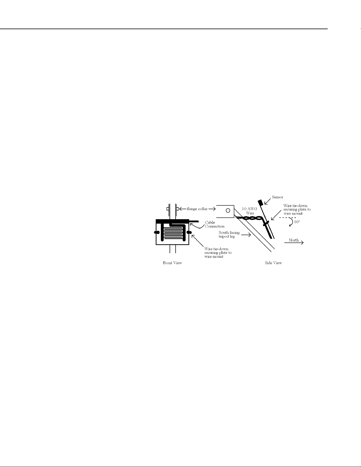
5.3 Sensor Deployment
The sensor is not supplied with a mounting bracket. Gillespie and Kidd1 found
that sensor orientation affects performance. As with surface preparation,
orientation varies across applications and users. A common practice is to
mount the sensor such that is receives minimal direct sunlight at mid-day
during the growing season. Gillespie and Kidd favor a 60 degree tilt on a north
facing sensor such that water runs away from the cable connection to minimize
puddling on the electrodes. Figure 2 shows a simple-to-construct mounting
bracket.
5.4 Calibration
FIGURE 2. Mounting the 237 Sensor
A wet / dry threshold of 150 kΩ is used in the programming examples in
Section 4. While this threshold may work well, refining the threshold for a
specific sensor and installation is recommended. A sharp change in resistance
occurs at the threshold on uncoated sensors. A less defined threshold occurs
with coated sensors. The threshold of uncoated sensors is normally between 50
and 200 kΩ. The threshold of the coated sensor is normally between 20 and
1,000 kΩ.
For best results, the sensor should be field calibrated. The transition point will
vary for different areas, vegetation, and water quality. Place the sensor in
vegetation, the wetness of which is to be monitored. Observe the vegetation
until it reaches the desired wetness. When the vegetation is at the desired
"wetness", the measured resistance can be used as a threshold. Sensitivity of
the sensor is changed by contaminants such as fingerprints and smudges.
Before painting and calibrating the sensor, clean it gently with alcohol.
7
Page 12

Model 237 Leaf Wetness Sensor
6. References
1
Gillespie, T.J. and Kidd, G.E. 1978. Sensing duration of leaf moisture
retention using electrical impedance grids. Can. J. Plant Sci. 58:179-187.
2
East, David (Ohio State University) 1994 Field Testing of Phone Accessible
Multi-Channel Datalogger for Tomato IPM Programs. Unpublished.
NOTE
The citation of researcher does not imply the endorsement of
Campbell Scientific products by any researcher or institution.
8
Page 13

Page 14

Campbell Scientific Companies
Campbell Scientific, Inc. (CSI)
815 West 1800 North
Logan, Utah 84321
UNITED STATES
www.campbellsci.com • info@campbellsci.com
Campbell Scientific Africa Pty. Ltd. (CSAf)
PO Box 2450
Somerset West 7129
SOUTH AFRICA
www.csafrica.co.za • cleroux@csafrica.co.za
Campbell Scientific Australia Pty. Ltd. (CSA)
PO Box 444
Thuringowa Central
QLD 4812 AUSTRALIA
www.campbellsci.com.au • info@campbellsci.com.au
Campbell Scientific do Brazil Ltda. (CSB)
Rua Luisa Crapsi Orsi, 15 Butantã
CEP: 005543-000 São Paulo SP BRAZIL
www.campbellsci.com.br • suporte@campbellsci.com.br
Campbell Scientific Canada Corp. (CSC)
11564 - 149th Street NW
Edmonton, Alberta T5M 1W7
CANADA
www.campbellsci.ca • dataloggers@campbellsci.ca
Campbell Scientific Centro Caribe S.A. (CSCC)
300 N Cementerio, Edificio Breller
Santo Domingo, Heredia 40305
COSTA RICA
www.campbellsci.cc • info@campbellsci.cc
Campbell Scientific Ltd. (CSL)
Campbell Park
80 Hathern Road
Shepshed, Loughborough LE12 9GX
UNITED KINGDOM
www.campbellsci.co.uk • sales@campbellsci.co.uk
Campbell Scientific Ltd. (France)
Miniparc du Verger - Bat. H
1, rue de Terre Neuve - Les Ulis
91967 COURTABOEUF CEDEX
FRANCE
www.campbellsci.fr • info@campbellsci.fr
Campbell Scientific Spain, S. L.
Avda. Pompeu Fabra 7-9, local 1
08024 Barcelona
SPAIN
www.campbellsci.es • info@campbellsci.es
Please visit www.campbellsci.com to obtain contact information for your local US or International representative.
 Loading...