

Page 1

223 Delmhorst Cylindrical
Soil Moisture Block
Revision: 5/13
Copyright © 1991-2013
Campbell Scientific, Inc.
Page 2

Page 3

Warranty
“PRODUCTS MANUFACTURED BY CAMPBELL SCIENTIFIC, INC. are
warranted by Campbell Scientific, Inc. (“Campbell”) to be free from defects in
materials and workmanship under normal use and service for twelve (12)
months from date of shipment unless otherwise specified in the corresponding
Campbell pricelist or product manual. Products not manufactured, but that are
re-sold by Campbell, are warranted only to the limits extended by the original
manufacturer. Batteries, fine-wire thermocouples, desiccant, and other
consumables have no warranty. Campbell’s obligation under this warranty is
limited to repairing or replacing (at Campbell’s option) defective products,
which shall be the sole and exclusive remedy under this warranty. The
customer shall assume all costs of removing, reinstalling, and shipping
defective products to Campbell. Campbell will return such products by surface
carrier prepaid within the continental United States of America. To all other
locations, Campbell will return such products best way CIP (Port of Entry)
INCOTERM® 2010, prepaid. This warranty shall not apply to any products
which have been subjected to modification, misuse, neglect, improper service,
accidents of nature, or shipping damage. This warranty is in lieu of all other
warranties, expressed or implied. The warranty for installation services
performed by Campbell such as programming to customer specifications,
electrical connections to products manufactured by Campbell, and product
specific training, is part of Campbell’s product warranty. CAMPBELL
EXPRESSLY DISCLAIMS AND EXCLUDES ANY IMPLIED
WARRANTIES OF MERCHANTABILITY OR FITNESS FOR A
PARTICULAR PURPOSE. Campbell is not liable for any special, indirect,
incidental, and/or consequential damages.”
Page 4

Assistance
Products may not be returned without prior authorization. The following
contact information is for US and international customers residing in countries
served by Campbell Scientific, Inc. directly. Affiliate companies handle
repairs for customers within their territories. Please visit
www.campbellsci.com to determine which Campbell Scientific company serves
your country.
To obtain a Returned Materials Authorization (RMA), contact CAMPBELL
SCIENTIFIC, INC., phone (435) 227-9000. After an applications engineer
determines the nature of the problem, an RMA number will be issued. Please
write this number clearly on the outside of the shipping container. Campbell
Scientific’s shipping address is:
CAMPBELL SCIENTIFIC, INC.
RMA#_____
815 West 1800 North
Logan, Utah 84321-1784
For all returns, the customer must fill out a “Statement of Product Cleanliness
and Decontamination” form and comply with the requirements specified in it.
The form is available from our web site at www.campbellsci.com/repair. A
completed form must be either emailed to repair@campbellsci.com or faxed to
(435) 227-9106. Campbell Scientific is unable to process any returns until we
receive this form. If the form is not received within three days of product
receipt or is incomplete, the product will be returned to the customer at the
customer’s expense. Campbell Scientific reserves the right to refuse service on
products that were exposed to contaminants that may cause health or safety
concerns for our employees.
Page 5

Table of Contents
PDF viewers: These page numbers refer to the printed version of this document. Use the
PDF reader bookmarks tab for links to specific sections.
1. Introduction.................................................................1
2. Cautionary Statements............................................... 1
3. Initial Inspection .........................................................1
4. Quickstart .................................................................... 2
4.1 Installation............................................................................................2
4.2 Use SCWin to Program Datalogger and Generate Wiring Diagram ....2
5. Overview......................................................................6
6. Specifications .............................................................7
7. Operation.....................................................................8
7.1 Wiring ..................................................................................................8
7.2 Programming........................................................................................9
7.2.1 Control the Multiplexer.................................................................9
7.2.1.1 CRBasic..............................................................................9
7.2.1.2 Edlog ................................................................................10
7.2.2 Excite and Measure the 223........................................................10
7.2.3 Calculate Sensor Resistance........................................................11
7.2.4 Calculate Soil Water Potential ....................................................11
7.2.5 Example Programs ......................................................................14
7.2.5.1 Example CR1000 Program...............................................14
7.2.5.2 Example CR10(X) Program .............................................16
7.2.5.3 Example 21X Program.....................................................18
Figures
7-1. 223 wiring ............................................................................................8
7-2. Polynomial fit to typical block resistance vs. water potential ............13
7-3. Wiring for CR1000 example..............................................................14
7-4. Wiring for CR10(X) example ............................................................16
7-5. Wiring for example 21X program......................................................18
Tables
7-1. 223 Wiring ...........................................................................................8
7-2. Excitation and Voltage Ranges ..........................................................10
7-3. Typical Soil Water Potential, Rs and Vs / Vx......................................12
i
Page 6

Table of Contents
7-4. Polynomial Coefficients for Converting Sensor Resistance to Bars.. 13
7-5. Polynomial Error – 10 Bar Range ..................................................... 13
ii
Page 7

223 Delmhorst Cylindrical
Soil Moisture Block
1. Introduction
The 223 is a gypsum block that determines soil water potential by measuring
electrical resistance. When the 223 is wet, electrical resistance is low. As the
223 dries, resistance increases. This gypsum block connects to a datalogger via
an AM16/32-series, AM32, or AM416 multiplexer.
The 223 gypsum soil moisture block is configured for use with multiplexers.
The –L option on the model 223-L indicates that the cable length is user
specified. This manual refers to the sensor as the 223.
Before using the 223, please study
• Section 2, Cautionary Statements
• Section 3, Initial Inspection
• Section 4, Quickstart
2. Cautionary Statements
• The black outer jacket of the cable is Santoprene
support combustion in air. It is rated as slow burning when tested
according to U.L. 94 H.B. and will pass FMVSS302. Local fire codes
may preclude its use inside buildings.
• Avoid installing in depressions where water will puddle after a rain storm.
• Don’t place the 223 in high spots or near changes in slope unless wanting
to measure the variability created by such differences.
• To maximize longevity, remove the gypsum blocks during the winter.
3. Initial Inspection
• Upon receipt of the 223, inspect the packaging and contents for damage.
File damage claims with the shipping company.
• The model number and cable length are printed on a label at the
connection end of the cable. Check this information against the shipping
documents to ensure the correct product and cable length are received.
®
rubber. This jacket will
1
Page 8
223 Delmhorst Cylindrical Soil Moisture Block
4. Quickstart
Please review Section 7, Operation, for wiring, CRBasic programming, and
Edlog programming.
4.1 Installation
1. Soak blocks in water for one hour then allow them to dry.
2. Repeat Step 1.
3. Make sensor access holes to the depth required.
4. Soak the blocks for two to three minutes.
5. Mix a slurry of soil and water to a creamy consistency and place one or
two tablespoons into the sensor access hole.
6. Place the blocks in the hole and force the slurry to envelope it. This will
insure uniform soil contact.
7. Back fill the hole, tamping lightly at frequent intervals.
4.2 Use SCWin to Program Datalogger and Generate Wiring Diagram
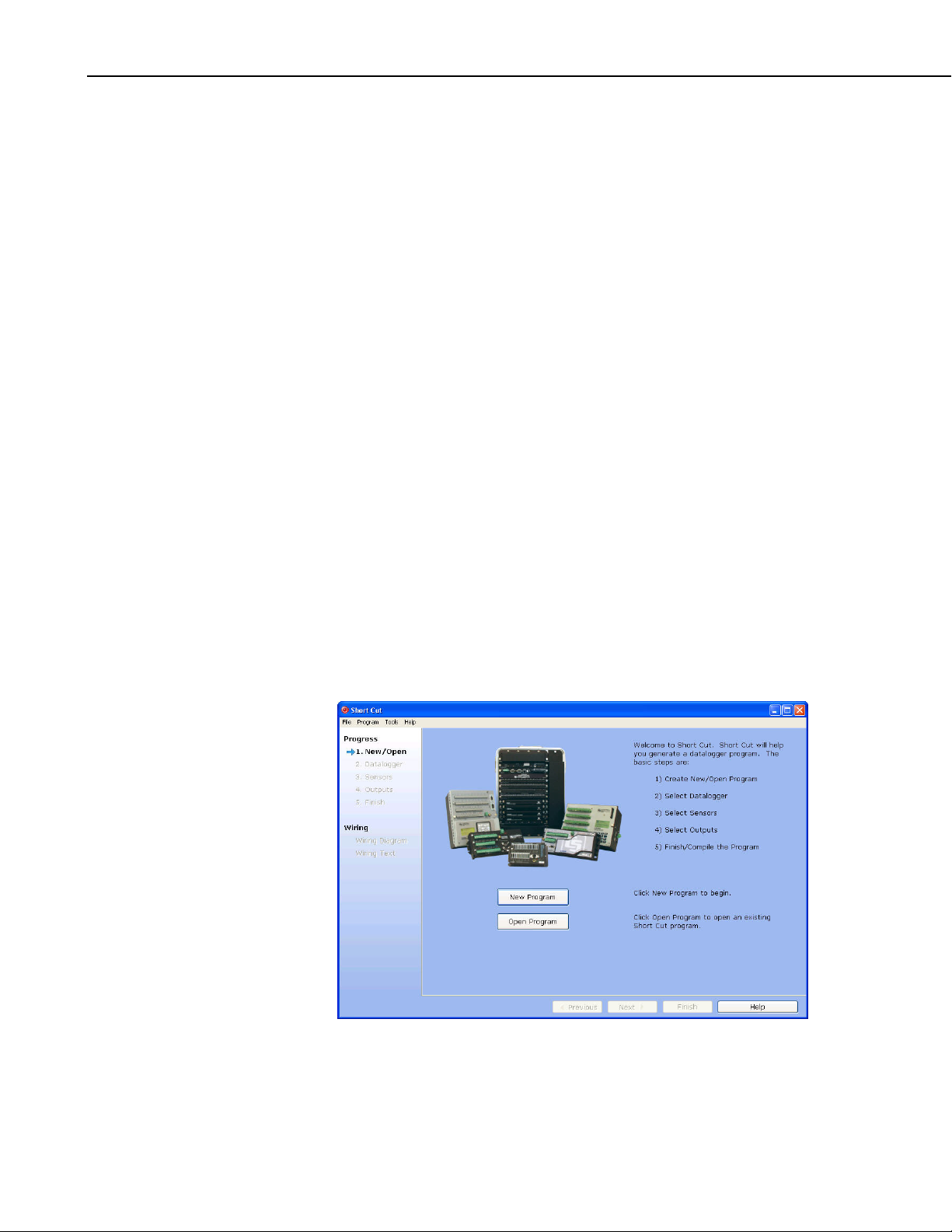
The simplest method for programming the datalogger to measure the 223 is to
use Campbell Scientific’s SCWin Short Cut Program Generator.
1. Open Short Cut and click on New Program.
2
Page 9
223 Delmhorst Cylindrical Soil Moisture Block
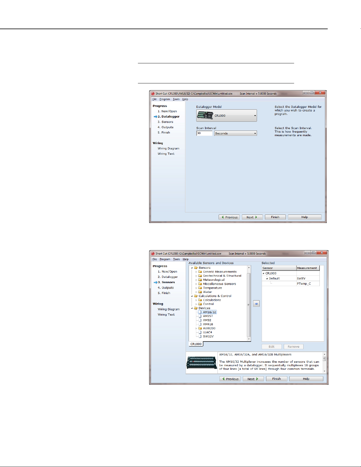
2. Select the Datalogger Model and enter the Scan Interval, and then select
Next.
NOTE
A scan rate of 30 seconds or longer is recommended when using
a multiplexer.
3. Under Devices, select AM16/32, and select the right arrow (in center of
screen) to add it to the list.
3
Page 10

223 Delmhorst Cylindrical Soil Moisture Block
4. Select 223 Soil Moisture Sensor, and select the right arrow (in center of
screen) to add it to the list of sensors to be measured. The Properties
window will appear after the right arrow is selected.
5. In the Properties window, enter the number of sensors, the Resistance
units, and the Soil Water Potential units. After entering the information,
click OK, and then select Next.
4
Page 11

223 Delmhorst Cylindrical Soil Moisture Block
6. Choose the Outputs and then select Finish.
7. In the Save As window, enter an appropriate file name and select Save.
8. In the Confirm window, click Yes to download the program to the
datalogger.
9. Click on Wiring Diagram and select the CR1000 tab. Wire the CR1000
to the AM16/32 according to the wiring diagram generated by SCWin
Short Cut.
5
Page 12

223 Delmhorst Cylindrical Soil Moisture Block
10. Select the AM16/32 tab and wire the 223 sensors to the AM16/32
according to the wiring diagram generated by SCWin Short Cut.
5. Overview
The 223 gypsum soil moisture block is configured for use with multiplexers.
The –L option on the model 223–L indicates that the cable length is user
specified. This manual refers to the sensor as the 223.
The Delmhorst cylindrical block is composed of gypsum cast around two
concentric electrodes which confine current flow to the interior of the block,
greatly reducing potential ground loops. Gypsum located between the outer
electrode and the soil creates a buffer against salts which may affect the
electrical conductivity. Individual calibrations are required for accurate
readings of soil water potential.
The multiplexer that the 223 is connected to leaves the circuit open when no
measurements are being made. This blocks direct current flow from the 223 to
datalogger ground and prevents electrolysis from prematurely destroying the
sensor.
The 223 should not be connected directly to the datalogger. The 227
Delmhorst soil moisture block is available for direct connection and has
capacitors in the cable that block direct current flow.
Gypsum blocks typically last for one to two years. Saline or acidic soils tend
to degrade the block, reducing longevity. To maximize longevity, gypsum
blocks not used during the winter should be removed from the field. Shallow
blocks may become frozen and crack, while blocks located below the frost line
may not maintain full contact with the soil. Regardless of depth, blocks left in
the field over winter are subject to the corrosive chemistry of the soil.
6
Page 13

6. Specifications
Features:
Compatible Dataloggers: CR800
CR850
CR1000
CR3000
CR5000
CR7
CR10(X)
21X
CR23X
223 Delmhorst Cylindrical Soil Moisture Block
• Compatible with multiplexers allowing measurement of multiple
sensors
• Multiplexer connection prevents electrolysis from prematurely
destroying the soil moisture block
• Measures a wide range of matric potential
• Buffers salts in soil
• No maintenance required
• Compatible with most Campbell Scientific dataloggers
Diameter: ~2.25 cm (0.88 in)
Length: ~2.86 cm (1.25 in)
Material: Gypsum
Electrode Configuration: Concentric cylinders
Center electrode: Excitation
Outer electrode: Ground
Calibration: Measurements are affected by soil salinity,
including fertilizer salts. Individual
calibrations are required for accurate
measurement of soil water potential. The soil
water potential versus resistance values in
TABLE 7-3 are “typical” values supplied by
Delmhorst Corporation. Neither Delmhorst
nor Campbell Scientific make any claim as to
the accuracy of these values. The calibration
equations in Section 7.2.4, Calculate Soil
Water Potential, were fit to the values in
TABLE 7-3 to allow output of an estimated
water potential.
7
Page 14

223 Delmhorst Cylindrical Soil Moisture Block
7. Operation
CAUTION
7.1 Wiring
The black outer jacket of the cable is Santoprene® rubber.
This compound was chosen for its resistance to
temperature extremes, moisture, and UV degradation.
However, this jacket will support combustion in air. It is
rated as slow burning when tested according to U.L. 94
H.B. and will pass FMVSS302. Local fire codes may
preclude its use inside buildings.
The 223 is shown in FIGURE 7-1 and TABLE 7-1. The leads from the block
electrodes are connected directly to the H and L inputs on the AM16/32-series,
AM32, or AM416 multiplexer. The lead from the center electrode (white
stripe or solid white) connects to H and the lead from the outer electrode
(black) to L. A 1k resistor at the datalogger is used to complete the half bridge
measurement.
Black with
White Stripe
(or White) to H
Black
to L
FIGURE 7-1. 223 wiring
TABLE 7-1. 223 Wiring
Color Function Multiplexer
Black w/ White Stripe or White Excitation H
Black Signal Ground L
8
Page 15

7.2 Programming
223 Delmhorst Cylindrical Soil Moisture Block
NOTE
This section describes using CRBasic or Edlog to program the
datalogger. See Section 4.2, Use SCWin to Program Datalogger
and Generate Wiring Diagram, if using Short Cut.
Dataloggers that use CRBasic include our CR800, CR850, CR1000, CR3000,
and CR5000. Dataloggers that use Edlog include our CR10(X), 21X, CR23X,
and CR7. CRBasic and Edlog are included with LoggerNet, PC400, and
RTDAQ software.
The datalogger program needs to control the multiplexer, measure the sensor,
calculate the sensor resistance, and convert the resistance to potential in bars.
Example programs are provided in Section 7.2.5, Example Programs.
7.2.1 Control the Multiplexer
When a multiplexer is used, the measurements are placed within a loop. Each
pass through the loop, the multiplexer is clocked to the next channel and the
sensors connected to that channel are measured. The programming sequence
for using the multiplexer is shown in Section 7.2.1.1, CRBasic, and Section
7.2.1.2, Edlog. For more information, see the multiplexer manual.
7.2.1.1 CRBasic
The generalized CRBasic programming sequence follows:
ACTIVATE MULTIPLEXER/RESET INDEX
Portset (1 ,1) 'Set C1 high to Enable Multiplexer
I=0
BEGIN MEASUREMENT LOOP
SubScan (0,sec,16) 'This example measures 16 sets
CLOCK PULSE AND DELAY
Portset (2,1) ‘Set port 2 high
Delay (0,20,mSec)
Portset (2,0) ‘Set port 2 low
INCREMENT INDEX AND MEASURE
I=I+1
‘223 measurement instruction
‘Storing results in Variable(I)
END MEASUREMENT LOOP
NextSubScan
DEACTIVATE MULTIPLEXER
Portset (1 ,0) 'Set C1 Low to disable Multiplexer
9
Page 16

223 Delmhorst Cylindrical Soil Moisture Block
7.2.1.2 Edlog
The generalized Edlog programming sequence follows:
ACTIVATE MULTIPLEXER/RESET INDEX
For the CR10(X) and CR23X, use Edlog instruction Do (P86) to set
the port high. For the 21X and CR7, use Edlog instruction Set
Port(s) (P20) to set the port high.
BEGIN MEASUREMENT LOOP
Use Edlog instruction Beginning of Loop (P87)
CLOCK PULSE AND DELAY
With the CR23X and CR10(X) the clock line is connected to a
control port. Instruction Do (P86) with the pulse port command
(71 – 78) pulses the clock line high for 10 ms. Instruction Excitation
with Delay (P22) can be added following the Do (P86) to delay an
additional 10 ms.
MEASURE SENSOR AND CALCULATE RESISTANCE
See Section 7.2.2, Excite and Measure the 223, and Section 7.2.3,
Calculate Sensor Resistance.
END MEASUREMENT LOOP
Use Edlog instruction End (P95).
DEACTIVATE MULTIPLEXER
For the CR10(X) and CR23X, use Edlog instruction Do (P86) to set
the port low. For the 21X and CR7, use Edlog instruction Set Port(s)
(P20) to set the port low.
7.2.2 Excite and Measure the 223
The sensor is excited and measured using the BrHalf instruction in CRBasic or
Instruction 5 (AC Half Bridge) in Edlog. Recommended excitation voltages
and input ranges are given in TABLE 7-2. TABLE 7-2 shows the excitation
and voltage ranges used with our dataloggers.
TABLE 7-2. Excitation and Voltage Ranges
Datalogger mV Excitation Full Scale Range
CR800/CR850 250 ±250 mV
CR1000 250 ±250 mV
CR3000 200 ±200 mV
CR5000 200 ±200 mV
21X 500 ±500 mV
CR7 500 ±500 mV
CR10(X) 250 ±250 mV
CR23X 200 ±200 mV
10
Page 17

223 Delmhorst Cylindrical Soil Moisture Block
The output from the BrHalf instruction or Instruction 5 is the ratio of signal
voltage to excitation voltage:
V
where, V
V
R
R
= Rs/(Rs + R1)
s/Vx
= Signal Voltage
s
= Excitation Voltage
x
= Sensor Resistance
s
= Fixed Bridge Resistor.
1
7.2.3 Calculate Sensor Resistance
The sensor resistance is calculated using an expression in CRBasic or Edlog
instruction BR Transform Rf[X/(1–X)] (P59). The expression or Edlog
instruction BR Transform Rf[X/(1–X)] (P59) takes the Half Bridge output
) and computes sensor resistance as follows:
(V
s/Vx
R
= R1(X/(1 – X))
s
where, X = V
s/Vx
The bridge transform multiplier would normally be 1000, representing the
fixed resistor (R
). A bridge multiplier of 1000 produces values of Rs larger
1
than 6999 ohms causing the datalogger to overrange when using low
resolution. To avoid overranging, a bridge multiplier of 1 should be used to
output sensor resistance (R
7.2.4 Calculate Soil Water Potential
) in terms of kohms.
s
The datalogger program can be written to store block resistance or can
calculate water potential from a block calibration. The soil water potential
versus resistance values in TABLE 7-3 are typical values supplied by
Delmhorst Corporation.
11
Page 18

223 Delmhorst Cylindrical Soil Moisture Block
TABLE 7-3. Typical Soil Water Potential,
BARS Rs (kohms) Vs/Vx
0.1 0.060 0.0566
0.2 0.130 0.1150
0.3 0.260 0.2063
0.4 0.370 0.2701
0.5 0.540 0.3506
0.6 0.750 0.4286
0.7 0.860 0.4624
0.8 1.100 0.5238
0.9 1.400 0.5833
1.0 1.700 0.6296
1.5 3.400 0.7727
and Vs / Vx
R
s
1.8 4.000 0.8000
2.0 5.000 0.8333
3.0 7.200 0.8780
6.0 12.500 0.9259
10.0 17.000 0.9444
11.0 22.200 0.9569
12.0 22.400 0.9573
13.0 30.000 0.9677
14.0 32.500 0.9701
15.0 35.000 0.9722
For the typical resistance values listed in TABLE 7-3, soil water potential
(bars) is calculated from sensor resistance (R
) using the 5th order polynomial
s
(FIGURE 7-2 and TABLE 7-4). TABLE 7-5 shows the polynomial error. The
nonlinear relationship of R
to bars rules out averaging Rs directly.
s
The polynomial is entered as an expression in CRBasic or by using Edlog
instruction Polynomial (P55). The polynomial to calculate soil water potential
is fit to the 0.1 to 10 bar range using a least square fit. TABLE 7-4 lists the
coefficients and equation for the 0.1 to 10 bar polynomial.
12
Page 19

223 Delmhorst Cylindrical Soil Moisture Block
Typical Values from TABLE 7-3
Block Resistance (kohms)
FIGURE 7-2. Polynomial fit to typical block resistance vs. water
potential
TABLE 7-4. Polynomial Coefficients for Converting Sensor Resistance to Bars
BARS = C0 + C1(Rs) + C2(Rs)2 + C3(Rs)3 + C4(Rs)4 + C5(Rs)5
(BARS) MULT. (R1) C0 C
C
1
C
2
C
3
C
4
5
0.1–10 0.1 0.15836 6.1445 –8.4189 9.2493 –3.1685 0.33392
TABLE 7-5. Polynomial Error – 10 Bar Range
BARS V
s/Vx
R
s
(kohms × 0.1)
BARS
COMPUTED ERROR
0.1 0.0566 0.006 0.1949 0.0949
0.2 0.115 0.013 0.2368 0.0368
0.3 0.2063 0.026 0.3126 0.0126
0.4 0.2701 0.037 0.3746 –0.0254
0.5 0.3506 0.054 0.4670 –0.0330
0.6 0.4286 0.075 0.5756 –0.0244
0.7 0.4624 0.086 0.6302 –0.0698
0.8 0.5238 0.11 0.7442 –0.0558
0.9 0.5833 0.14 0.8778 –0.0222
1.0 0.6296 0.17 1.0025 0.0025
1.5 0.7727 0.34 1.5970 0.0970
1.8 0.8000 0.40 1.7834 –0.0166
2 0.8333 0.50 2.0945 0.0945
3 0.8780 0.72 2.8834 –0.1166
6 0.9259 1.25 6.0329 0.0329
10 0.9444 1.70 9.9928 –0.0072
ERROR (BARS) = TABLE 7-3 VALUES – COMPUTED VALUES
13
Page 20

223 Delmhorst Cylindrical Soil Moisture Block
7.2.5 Example Programs
7.2.5.1 Example CR1000 Program
Below is a CR1000 program that measures five 223 sensors, calculates
resistance, and calculates soil water potential.
'CR1000
'Declare Variables and Units
Dim LCount
Public BattV
Public PTemp_C
Public kohms(5)
Public WP_kPa(5)
Units BattV=Volts
Units PTemp_C=Deg C
Units kohms=kilohms
Units WP_kPa=kPa
14
FIGURE 7-3. Wiring for CR1000 example
Page 21

223 Delmhorst Cylindrical Soil Moisture Block
'Define Data Tables
DataTable(Table1,True,–1)
DataInterval(0,60,Min,10)
Sample(1,kohms(1),FP2)
Sample(1,WP_kPa(1),FP2)
Sample(1,kohms(2),FP2)
Sample(1,WP_kPa(2),FP2)
Sample(1,kohms(3),FP2)
Sample(1,WP_kPa(3),FP2)
Sample(1,kohms(4),FP2)
Sample(1,WP_kPa(4),FP2)
Sample(1,kohms(5),FP2)
Sample(1,WP_kPa(5),FP2)
EndTable
DataTable(Table2,True,–1)
DataInterval(0,1440,Min,10)
Minimum(1,BattV,FP2,False,False)
EndTable
'Main Program
BeginProg
'Main Scan
Scan(30,Sec,1,0)
'Default Datalogger Battery Voltage measurement 'BattV'
Battery(BattV)
'Default Wiring Panel Temperature measurement 'PTemp_C'
PanelTemp(PTemp_C,_60Hz)
'Turn AM16/32 Multiplexer On
PortSet(2,1)
Delay(0,150,mSec)
LCount=1
SubScan(0,uSec,5)
'Switch to next AM16/32 Multiplexer channel
PulsePort(1,10000)
'223 Soil Moisture Sensor measurements 'kohms()' and 'WP_kPa()' on the AM16/32 Multiplexer
BrHalf(kohms(LCount),1,mV250,1,1,1,250,True,20000,250,1,0)
'Convert resistance ratios to kilohms and kilohms to water potential
kohms(LCount)=kohms(LCount)/(1–kohms(LCount))
If kohms(LCount)<17 Then
WP_kPa(LCount)=kohms(LCount)*0.1
WP_kPa(LCount)=0.15836+(6.1445*WP_kPa(LCount))+(–8.4189*WP_kPa(LCount)^2)+(9.2493*WP_kPa(LCount)^3)+(–3.1685*WP_kPa(LCount)^4)+(0.33392*WP_kPa(LCount)^5)
WP_kPa(LCount)=WP_kPa(LCount)*100
Else
WP_kPa(LCount)=1000
EndIf
LCount=LCount+1
NextSubScan
'Turn AM16/32 Multiplexer Off
PortSet(2,0)
Delay(0,150,mSec)
'Call Data Tables and Store Data
CallTable(Table1)
CallTable(Table2)
NextScan
EndProg
15
Page 22

223 Delmhorst Cylindrical Soil Moisture Block
7.2.5.2 Example CR10(X) Program
CR10(X)
Multiplexer
FIGURE 7-4. Wiring for CR10(X) example
*Table 1 Program
01: 60.0000 Execution Interval (seconds)
01: Do (P86) ;Enable multiplexer
1: 41 Set Port 1 High
02: Beginning of Loop (P87) ;Start of measurement loop
1: 0 Delay
2: 16 Loop Count
03: Do (P86) ;Clock Multiplexer to next channel
1: 72 Pulse Port 2
04: Step Loop Index (P90) ;Step index by 2 each pass through loop
1: 2 Step
05: AC Half Bridge (P5) ;Measure the 2 connected 223 blocks
1: 2 Reps
2: 14 250 mV Fast Range
3: 1 SE Channel
4: 2 Excite all reps w/Exchan 2
5: 250 mV Excitation
6: 1-- Loc [ BlockR_1 ] ;-- >>> advance location by index
7: 1.0 Mult
8: 0.0 Offset
06: BR Transform Rf[X/(1–X)] (P59) ;Calculate resistance from Vs/Vx
1: 2 Reps
2: 1-- Loc [ BlockR_1 ]
3: 1 Multiplier (Rf)
07: End (P95)
16
Page 23

223 Delmhorst Cylindrical Soil Moisture Block
08: Do (P86) ;Turn off multiplexer
1: 51 Set Port 1 Low
;The following loop checks each block resistance and calculates
;water potential if BlockR < 17 kohms. Because 2 blocks are measured
;with each pass through the previous measurement loop, it is simpler
;to use a separate loop for the calculations.
;Leave out following loop if only recording block resistance.
09: Beginning of Loop (P87) ;Loop to calculate water potential
1: 0 Delay
2: 32 Loop Count
10: If (X<=>F) (P89) ;If Rs < 17, apply polynomial
1: 1-- X Loc [ BlockR_1 ]
2: 4 <
3: 17 F
4: 30 Then Do
11: Z=X*F (P37) ;Scale Rs for polynomial
1: 1-- X Loc [ BlockR_1 ]
2: .1 F
3: 33-- Z Loc [ WatPot_1 ]
12: Polynomial (P55) ;Convert Rs to bars with 10 bar polynomial
1: 1 Reps
2: 33-- X Loc [ WatPot_1 ]
3: 33-- F(X) Loc [ WatPot_1 ]
4: .15836 C0
5: 6.1445 C1
6: –8.4198 C2
7: 9.2493 C3
8: –3.1685 C4
9: .33392 C5
13: Else (P94) ;If Rs > 17 load over range value for potential
14: Z=F (P30)
1: –99999 F
2: 0 Exponent of 10
3: 33 Z Loc [ WatPot_1 ]
15: End (P95) ;End then do
16: End (P95) ;End loop
17: If time is (P92) ;Output Resistance and Water Potential each
Hour
1: 0 Minutes (Seconds --) into a
2: 60 Interval (same units as above)
3: 10 Set Output Flag High (Flag 0)
18: Set Active Storage Area (P80) ;Fix the Array ID to 60
1: 1 Final Storage Area 1
2: 60 Array ID
17
Page 24

223 Delmhorst Cylindrical Soil Moisture Block
19: Real Time (P77) ;Output Day and Hour/Minute
1: 220 Day,Hour/Minute (midnight = 2400)
20: Sample (P70) ;Output resistances and Water Potentials
1: 64 Reps
2: 1 Loc [ BlockR_1 ]
7.2.5.3 Example 21X Program
21X
FIGURE 7-5. Wiring for example 21X program
*Table 1 Program
01: 10 Execution Interval (seconds)
01: Set Port (P20) ;Enable multiplexer
1: 1 Set High
2: 1 Port Number
02: Beginning of Loop (P87) ;Start of measurement loop
1: 0 Delay
2: 16 Loop Count
03: Excitation with Delay (P22) ;Clock Multiplexer to next channel
1: 1 Ex Channel
2: 1 Delay w/Ex (units = 0.01 sec)
3: 1 Delay After Ex (units = 0.01 sec)
4: 5000 mV Excitation
04: Step Loop Index (P90) ;Step index by 2 each pass through loop
1: 2 Step
Multiplexer
18
Page 25

223 Delmhorst Cylindrical Soil Moisture Block
05: AC Half Bridge (P5) ;Measure the 2 connected 223 blocks
1: 2 Reps
2: 14 500 mV Fast Range
3: 1 SE Channel
4: 2 Excite all reps w/Exchan 2
5: 500 mV Excitation
6: 1-- Loc [ BlockR_1 ] ; -- >>> advance location by index
7: 1.0 Mult
8: 0.0 Offset
06: BR Transform Rf[X/(1–X)] (P59) ;Calculate resistance from Vs/Vx
1: 2 Reps
2: 1-- Loc [ BlockR_1 ]
3: 1.0 Mult (Rf)
07: End (P95)
08: Set Port (P20) ;Turn off AM416
1: 0 Set Low
2: 1 Port Number
;The following loop checks each block resistance and calculates
;water potential if BlockR < 17 kohms. Because 2 blocks are measured
;with each pass through the previous measurement loop, it is simpler
;to use a separate loop for the calculations.
;Leave out following loop if only recording block resistance.
09: Beginning of Loop (P87) ;Loop to calculate water potential
1: 0 Delay
2: 32 Loop Count
10: If (X<=>F) (P89) ;If Rs < 17, apply polynomial
1: 1-- X Loc [ BlockR_1 ]
2: 4 <
3: 17 F
4: 30 Then Do
11: Z=X*F (P37) ;Scale Rs for polynomial
1: 1-- X Loc [ BlockR_1 ]
2: .1 F
3: 33-- Z Loc [ WatPo_1 ]
12: Polynomial (P55) ;Convert Rs to bars with 10 bar polynomial
1: 1 Reps
2: 33-- X Loc [ WatPo_1 ]
3: 33-- F(X) Loc [ WatPo_1 ]
4: .15836 C0
5: 6.1445 C1
6: –8.4198 C2
7: 9.2493 C3
8: –3.1685 C4
9: .33392 C5
13: Else (P94) ;If Rs > 17 load overrange value for potential
19
Page 26

223 Delmhorst Cylindrical Soil Moisture Block
14: Z=F (P30)
1: –99999 F
2: 33-- Z Loc [ WatPo_1 ]
15: End (P95) ;End then do
16: End (P95) ;End loop
17: If time is (P92) ;Output Resistance and Water Potential each
1: 0 Minutes (Seconds --) into a
2: 60 Interval (same units as above)
3: 10 Set Output Flag High (Flag 0)
18: Set Active Storage Area (P80) ;Fix the Array ID to 60
1: 1 Final Storage Area 1
2: 60 Array ID
19: Real Time (P77) ;Output Day and Hour/Minute
1: 220 Day,Hour/Minute (midnight = 2400)
20: Sample (P70) ;Output resistances and Water Potentials
1: 64 Reps ;32 reps if not outputting water potential
2: 1 Loc [ BlockR_1 ]
Hour
20
Page 27

Page 28

Campbell Scientific Companies
Campbell Scientific, Inc. (CSI)
815 West 1800 North
Logan, Utah 84321
UNITED STATES
www.campbellsci.com • info@campbellsci.com
Campbell Scientific Africa Pty. Ltd. (CSAf)
PO Box 2450
Somerset West 7129
SOUTH AFRICA
www.csafrica.co.za • cleroux@csafrica.co.za
Campbell Scientific Australia Pty. Ltd. (CSA)
PO Box 8108
Garbutt Post Shop QLD 4814
AUSTRALIA
www.campbellsci.com.au • info@campbellsci.com.au
Campbell Scientific do Brasil Ltda. (CSB)
Rua Apinagés, nbr. 2018 ─ Perdizes
CEP: 01258-00 ─ São Paulo ─ SP
BRASIL
www.campbellsci.com.br • vendas@campbellsci.com.br
Campbell Scientific Canada Corp. (CSC)
11564 - 149th Street NW
Edmonton, Alberta T5M 1W7
CANADA
www.campbellsci.ca • dataloggers@campbellsci.ca
Campbell Scientific Centro Caribe S.A. (CSCC)
300 N Cementerio, Edificio Breller
Santo Domingo, Heredia 40305
COSTA RICA
www.campbellsci.cc • info@campbellsci.cc
Campbell Scientific Ltd. (CSL)
Campbell Park
80 Hathern Road
Shepshed, Loughborough LE12 9GX
UNITED KINGDOM
www.campbellsci.co.uk • sales@campbellsci.co.uk
Campbell Scientific Ltd. (France)
3 Avenue de la Division Leclerc
92160 ANTONY
FRANCE
www.campbellsci.fr • info@campbellsci.fr
Campbell Scientific Spain, S. L.
Avda. Pompeu Fabra 7-9, local 1
08024 Barcelona
SPAIN
www.campbellsci.es • info@campbellsci.es
Please visit www.campbellsci.com to obtain contact information for your local US or international representative.
 Loading...