

Page 1

110PV Surface
Temperature Probe
Revision: 10/11
Copyright © 2010-2011
Campbell Scientific, Inc.
Page 2

Page 3

Warranty
“PRODUCTS MANUFACTURED BY CAMPBELL SCIENTIFIC, INC. are
warranted by Campbell Scientific, Inc. (“Campbell”) to be free from defects in
materials and workmanship under normal use and service for twelve (12)
months from date of shipment unless otherwise specified on the corresponding
Campbell invoice. Batteries, fine-wire thermocouples, desiccant, and other
consumables have no warranty. Campbell's obligation under this warranty is
limited to repairing or replacing (at Campbell's option) defective products,
which shall be the sole and exclusive remedy under this warranty. The
customer shall assume all costs of removing, reinstalling, and shipping
defective products to Campbell. Campbell will return such products by surface
carrier prepaid within the continental United States of America. To all other
locations, Campbell will return such products best way CIP (Port of Entry)
INCOTERM® 2010, prepaid. This warranty shall not apply to any Campbell
products which have been subjected to modification, misuse, neglect, improper
service, accidents of nature, or shipping damage. This warranty is in lieu of all
other warranties, expressed or implied. The warranty for installation services
performed by Campbell such as programming to customer specifications,
electrical connections to products manufactured by Campbell, and product
specific training, is part of Campbell’s product warranty. CAMPBELL
EXPRESSLY DISCLAIMS AND EXCLUDES ANY IMPLIED
WARRANTIES OF MERCHANTABILITY OR FITNESS FOR A
PARTICULAR PURPOSE. Campbell is not liable for any special, indirect,
incidental, and/or consequential damages.”
Page 4

Assistance
Products may not be returned without prior authorization. The following
contact information is for US and international customers residing in countries
served by Campbell Scientific, Inc. directly. Affiliate companies handle
repairs for customers within their territories. Please visit
www.campbellsci.com to determine which Campbell Scientific company serves
your country.
To obtain a Returned Materials Authorization (RMA), contact CAMPBELL
SCIENTIFIC, INC., phone (435) 227-2342. After an applications engineer
determines the nature of the problem, an RMA number will be issued. Please
write this number clearly on the outside of the shipping container. Campbell
Scientific's shipping address is:
CAMPBELL SCIENTIFIC, INC.
RMA#_____
815 West 1800 North
Logan, Utah 84321-1784
For all returns, the customer must fill out a "Statement of Product Cleanliness
and Decontamination" form and comply with the requirements specified in it.
The form is available from our web site at www.campbellsci.com/repair. A
completed form must be either emailed to repair@campbellsci.com or faxed to
(435) 227-9579. Campbell Scientific is unable to process any returns until we
receive this form. If the form is not received within three days of product
receipt or is incomplete, the product will be returned to the customer at the
customer's expense. Campbell Scientific reserves the right to refuse service on
products that were exposed to contaminants that may cause health or safety
concerns for our employees.
Page 5

110PV Table of Contents
PDF viewers: These page numbers refer to the printed version of this document. Use the
PDF reader bookmarks tab for links to specific sections.
1. General .........................................................................1
1.1 Specifications............................................................................................2
2. Accuracy.......................................................................3
3. Installation and Wiring ................................................7
3.1 Placement on a Photovoltaic (PV) Module...............................................7
3.2 Mounting to a PV Module or Other Device .............................................8
3.3 Cable Strain Relief....................................................................................8
3.4 Submersion ...............................................................................................9
4. Wiring............................................................................9
5. Programming .............................................................10
5.1 CRBasic ..................................................................................................11
5.1.1 CRBasic Examples........................................................................11
5.1.1.1 Sample Program for CR200(X) Series Datalogger .............12
5.1.1.2 Sample Half Bridge Program for CR1000 Datalogger........13
5.1.1.3 Sample 4-Wire Half BridgeProgram for CR1000...............14
5.2 Edlog.......................................................................................................15
5.2.1 Example Edlog Program...............................................................15
5.3 Electrical Noisy Environments ...............................................................17
5.4 Long Lead Lengths.................................................................................17
6. Measurement..............................................................18
7. Maintenance, Removal, and Calibration..................19
7.1 Maintenance............................................................................................19
7.2 Removal from Measurement Surface .....................................................19
7.3 Recalibrations/Repairs............................................................................19
8. Troubleshooting ........................................................19
Appendices
A. Probe Material Properties
A.1 3M 9485PC Adhesive......................................................................... A-1
A.2 Santoprene .......................................................................................... A-1
i
Page 6

110PV Table of Contents
Figures
Tables
1-1. 110PV Temperature Probe ..................................................................... 1
2-1. Steinhart-Hart Error................................................................................ 3
2-2. 110PV measured with a 3-wire half bridge ............................................ 4
2-3. 110PV measured with a CR1000 using a 4-wire half bridge ................. 4
2-4. 110PV measured with a CR1000 showing effects of cable length
when using a cable offset .................................................................... 5
2-5. 110PV measured with a CR1000 showing effects of cable length......... 5
2-6. 110PV measured with a CR200(X) showing effects of cable length
when a cable offset is used .................................................................. 6
2-7. 110PV measured with a CR200(X) showing effects of cable length ..... 6
3-1. 110PV mounted to a PV module ............................................................ 7
3-2. At left is a PV module with distinctive solar cells. At right is a PV
module that does not have distinctive solar cells. ............................... 7
3-3. 110PV mounted to a PV module using Kapton tape .............................. 8
3-4. 110PV’s strain relief label ...................................................................... 9
6-1. 110PV Thermistor Probe schematic ..................................................... 18
4-1. Connections to Campbell Scientific Dataloggers ................................. 10
5-1. Wiring for Example Programs.............................................................. 11
5-2. Wiring for Example Program ............................................................... 15
ii
Page 7
110PV Surface Temperature Probe
1. General
The 110PV-L temperature probe uses a thermistor to measure temperature.
The probe is designed for measuring the back of photovoltaic (PV) module
temperature but also can be used to measure other surface temperatures. The
110PV-L is compatible with all Campbell Scientific dataloggers.
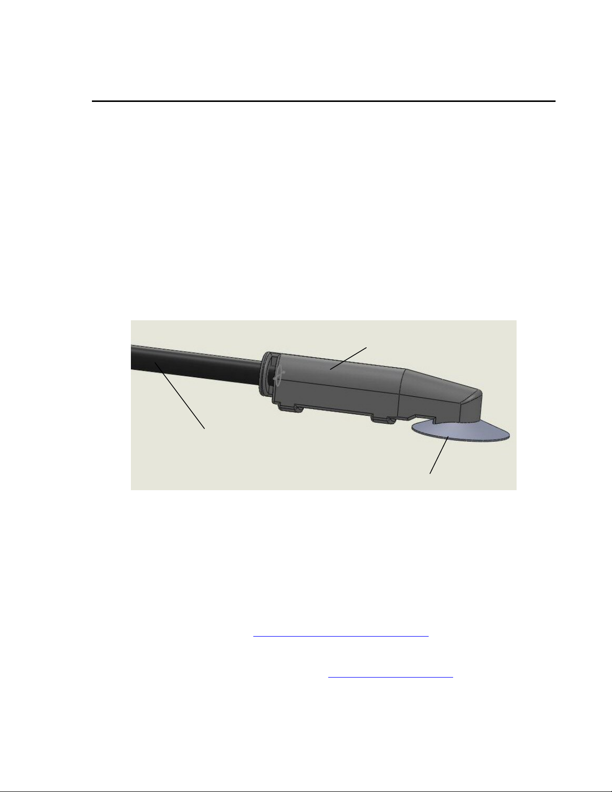
The 110PV-L consists of a thermistor encased in an aluminum disk (see Figure
1-1). The aluminum disk protects the thermistor and promotes heat transfer
from surfaces.
The probe measures temperature from –40° to +135°C. For temperatures up to
70°C, an adhesive tab on the probe’s aluminum disk fastens the 110PV to the
measurement surface. If the temperature may exceed 70°C, Kapton tape or
high temperature epoxy is recommend to secure the probe to the measurement
surface. Kapton tape (P/N 27015) is available from Campbell Scientific.
Overmolded joint
Santoprene-jacketed cable
Thermistor encased in an aluminum disk
FIGURE 1-1. 110PV Temperature Probe
The –L portion of the probes model number indicates the probe has a user
defined cable length which will be specified when the probe is ordered.
The probe’s cable can terminate in:
• Pigtails that connect directly to a Campbell Scientific datalogger (option
–PT).
• Connector that attaches to a prewired enclosure (option –PW). Refer to
www.campbellsci.com/prewired-enclosures
• Connector that attaches to a CWS900 Wireless Sensor Interface (option
–CWS). The CWS900 allows the 110PV to be used in a wireless sensor
network. Refer to www.campbellsci.com/cws900
For readability purposes, the probe will be referred to as the 110PV throughout
this document.
for more information.
for more information.
1
Page 8

110PV Surface Temperature Probe
The 110PV ships with:
1.1 Specifications
Temperature Range: -40° to +135°C
Survival Range: -50° to +140°C
110PV Temperature Uncertainty
-40° to 70°C: ±0.2°C
71° to 105°C: ±0.5°C
106° to 135°C: ±1°C
Time Constant (average):
Test
Still Air 252 seconds
Surface 25 seconds
1) Adhesive Backed 3 cm Cable Tie Mount
2) Cable Ties 8” UV Stabilized
3) Resource CD
τ
Water Submersion Depth: 50 ft (21 psi)
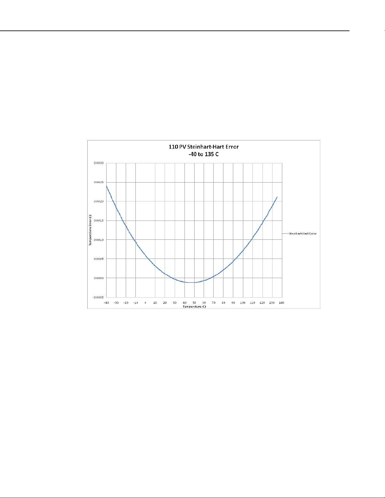
Linearization Error: Steinhart & Hart equation; maximum error is 0.0024°C at
-40°C.
Maximum Cable Length: 1000 ft
Disk Diameter: 1.0 in. (2.54 cm)
Overall Probe Length: 2.5 in. (6.35 cm)
Overmolded Joint Dimensions:
Width: 0.44 in. (1.12 cm)
Height: 0.58 in. (1.47 cm)
Length: 2.25 in. (5.72 cm
Cable Diameter: 0.245 in. (0.622 cm)
Material
Disk: Anodized Aluminum
Cable Jacket: Santoprene
Cable/Probe Connection: Santoprene
Weight: 0.2 lbs (90.7 g) with 10.5 ft (3.2 m) cable
2
NOTE
The black outer jacket of the cable is Santoprene
compound was chosen for its resistance to temperature extremes,
moisture, and UV degradation. However, this jacket will support
combustion in air. It is rated as slow burning when tested
according to U.L. 94 H.B. and will pass FMVSS302. Local fire
codes may preclude its use inside buildings.
®
rubber. This
Page 9
2. Accuracy
110PV Surface Temperature Probe
The overall probe accuracy is a combination of the thermistor's
interchangeability specification and the accuracy of the bridge resistor. The
Steinhart-Hart equation used to calculate temperature has a negligible error
(Figure 2-1). In a "worst case" the errors add to an accuracy of ±0.2°C over
the range of -40° to 70°C; ±0.5°C over the range of 71°C to 105°C; and ±1°C
from 106°C to 135°C. The major error component is the interchangeability
specification (tolerance) of the thermistor. The bridge resistor has a 0.1%
tolerance with a 10 ppm temperature coefficient. Figures 2-2 to 2-7 show the
possible worst case probe and measurement errors.
FIGURE 2-1. Steinhart-Hart Error
3
Page 10

110PV Surface Temperature Probe
Uncertainty on the graphs below is symmetric about 0.
FIGURE 2-2. 110PV measured with a 3-wire half bridge
4
FIGURE 2-3. 110PV measured with a CR1000 using a 4-wire half bridge
Page 11

110PV Surface Temperature Probe
FIGURE 2-4. 110PV measured with a CR1000 showing effects of cable length
when using a cable offset
FIGURE 2-5. 110PV measured with a CR1000 showing effects of cable length
5
Page 12

110PV Surface Temperature Probe
FIGURE 2-6. 110PV measured with a CR200(X) showing effects of cable length
when a cable offset is used
6
FIGURE 2-7. 110PV measured with a CR200(X) showing effects of cable length
Page 13

3. Installation and Wiring
3.1 Placement on a Photovoltaic (PV) Module
The 110PV should be centered on the back of the PV module (see Figure 3-1).
If the module has several distinctive photocells (see Figure 3-2), the 110PV
should also be centered on the back of a photocell.
110PV Surface Temperature Probe
FIGURE 3-1. 110PV mounted to a PV module
FIGURE 3-2. At left is a PV module with distinctive solar cells.
At right is a PV module that does not have distinctive solar cells.
7
Page 14

110PV Surface Temperature Probe
3.2 Mounting to a PV Module or Other Device
For mounting the probe to the back of a PV module or another device, the
110PV comes with an adhesive mounting disc adhered to its flat surface. To
mount the 110PV, remove the paper from the mounting disc and adhere it to
the back of the PV module or other device; refer to Section 3.1 for proper
placement on a PV module. The mounting disc must be adhered to a clean
surface for its adhesive to function properly.
If the temperature is expected to exceed 70°C, use Kapton tape, epoxy, or other
means to secure the probe to the measurement surface (see Figure 3-3); a roll
of Kapton tape (P/N 27015) is offered by Campbell Scientific as a Common
Accessory.
8
FIGURE 3-3. 110PV mounted to a PV module using Kapton tape
3.3 Cable Strain Relief
The 110PV’s cable must be properly strain relieved after mounting the probe to
the measurement surface. To accomplish this, the probe comes with cable ties
and a cable tie mount. A yellow label on the 110PV’s cable indicates where
you should tie down the cable (see Figures 3-3 and 3-4).
NOTE
Placement of the cable inside a rugged conduit is advisable for
long cable runs, especially in locations subject to digging,
mowing, traffic, use of power tools, animals, or lightning strikes.
Page 15

3.4 Submersion
110PV Surface Temperature Probe
FIGURE 3-4. 110PV’s strain relief label
The 110PV can be submerged to 50 ft. It must be adhered to a dry clean
surface before submerging. The probe’s adhesive mounting disc is not
intended for submersion. Therefore the 110PV must be mounted to the
measurement surface via a user-supplied method that is compatible with
submersion.
4. Wiring
Connections to Campbell Scientific dataloggers are given in Table 4-1. Most
CRBasic dataloggers can measure the 110PV using either a 4-wire half bridge
or 3-wire half bridge. The CR200(X) and Edlog dataloggers can only use a
3-wire half bridge. The 4-wire half bridge method is preferred because it
reduces cable errors (see Figures 2-2 and 2-3). The 4-wire half bridge method
requires two differential input channels and one voltage excitation channel.
The 3-wire half bridge method uses one single-ended input channel and one
voltage excitation channel.
Multiple probes can be connected to the same excitation channel. The number
of probes per excitation channel is physically limited by the number of lead
wires that can be inserted into a single voltage excitation terminal,
approximately six.
9
Page 16

110PV Surface Temperature Probe
TABLE 4-1. Connections to Campbell Scientific Dataloggers
Color
Black
Description
Voltage
Excitation
Red Signal
Purple
Signal
Reference
Blue
Signal
Reference
Clear Shield
Green Sense +
White Sense -
4-Wire
Half Bridge
CR800
CR850
CR3000
CR1000
CR5000
Switched
Voltage
Excitation
Differential
Input (H)
Differential
Input (L)
Differential
Input (H)
Differential
Input (L)
3-Wire
Half Bridge
CR200(X)
CR800
CR850
CR3000
CR1000
CR5000
Switched
Voltage
Excitation
SingleEnded Input
3-Wire
Half Bridge
CR510
CR500
CR10(X)
Switched
Voltage
Excitation
Single-Ended
Input
AG
3-Wire
Half Bridge
21X
CR7
CR23X
Switched
Voltage
Excitation
Single-Ended
Input
Not Used Not Used Not Used
G
Not Used Not Used Not Used
Not Used Not Used Not Used
5. Programming
NOTE
This section is for users who write their own datalogger
programs. A datalogger program to measure this sensor can be
generated using Campbell Scientific’s Short Cut Program
Builder software. You do not need to read this section to use
Short Cut.
The datalogger is programmed using either CRBasic or Edlog. Dataloggers
that use CRBasic include our CR200(X) series, CR800, CR850, CR1000,
CR3000, CR5000, and CR9000(X); see Section 5.1. Dataloggers that use
Edlog include our CR10, CR10X, CR23X, and CR7; refer to Section 5.2.
CRBasic and Edlog are included in our LoggerNet, PC400, and RTDAQ
software.
The Steinhart-Hart equation is used to calculate the temperature. The
coefficients used for the Steinhart-Hart equation are as follows:
A=1.129241*10^-3
B=2.341077*10^-4
C=8.775468*10^-8
If applicable, please read “Section 5.3—Electrical Noisy Environments” and
“Section 5.4—Long Lead Lengths” prior to programming your datalogger.
Measurement details are provided in Section 6.
10
Page 17

5.1 CRBasic
110PV Surface Temperature Probe
The CR200(X)-series dataloggers use the ExDelSe instruction to measure the
110PV (see example in Section 5.1.1.1). The ExDelSe instruction has the
following syntax:
ExDelSE( Dest, Reps, SEChan, ExChan, ExmV, Delay, Mult, Offset )
The CR800, CR850, CR1000, CR3000, CR5000, and CR9000(X) can use
either the BrHalf4W instruction or BrHalf instruction to measure the 110PV
(see examples in Sections 5.1.1.2 and 5.1.1.3).
For these dataloggers, the BrHalf4W instruction is typically preferred because
it reduces cable errors (see Figures 2-2 and 2-3). The BrHalf instruction
requires fewer input channels.
A typical BrHalf4W instruction follows:
BrHalf4W (Dest,1,mV2500,mV2500,1,Vx1,1,2500,True ,True ,0,250,1.0,0)
A typical BrHalf instruction follows:
BrHalf (Dest,1,mV2500,1,Vx1,1,2500,True ,0,250,1.0,0)
A multiplier of 1.0 and offset of 0.0 should be used in the ExDelSe, BrHalf4W,
and BrHalf instructions to yield a temperature in degrees Celsius. For
Fahrenheit multiply the calculated Celsius temperature by 1.8 then add 32.
5.1.1 CRBasic Examples
TABLE 5-1. Wiring for Example Programs
Black Voltage Excitation VX1 or EX1 VX1 or EX1
Red Signal SE1 Diff 1H
Purple Signal Reference
Blue Signal Reference Not Used
Clear Shield
Green Sense + Not Used Diff 2H
White Sense - Not Used Diff 2L
Datalogger Connection Color Description
BrHalf BrHalf4W
Diff 1L
11
Page 18

110PV Surface Temperature Probe
5.1.1.1 Sample Program for CR200(X) Series Datalogger
'CR200 Series Datalogger
'This example program measures a single 110PV-L probe
'once a second using the ExDelSE instruction and stores
'the average temperature in degrees C every 10 minutes.
'110PV-L Wiring configuration for program example
'Lead Color CR200(X) Channel Description
'Black ------ VX1 ------------ Voltage Excitation
'Red -------- SE1------------- Signal
'Purple----- AG-------------- Signal Reference
'Blue ------- Not Used ------ N/A
'Green ----- Not Used ------ N/A
'White------ Not Used ------ N/A
'Clear------ AG-------------- Shield
'Declare variables for temperature measurement
Public T110PV_mV
Public T110PV_Res
Public T110PV_Temp_C
Public T110PV_Temp_F
'Declare constants to be used in Steinhart-Hart equation
Const A=1.129241*10^-3
Const B=2.341077*10^-4
Const C=8.775468*10^-8
Const R_cable=0 'see sensor cable for cable resistance
'Declare variable units
Units T110PV_mV= millivolts
Units T110PV_Res=Ohms
Units T110PV_Temp_C=Deg C
'Define a data table for 10 minute averages
DataTable (AvgTemp,1,1000)
DataInterval (0,10,min)
Average (1,T110PV_Temp_C,False)
EndTable
'Main Program
BeginProg
Scan (1,Sec)
' Measure 110PV-L probe with SE1
ExDelSE (T110PV_mV,1,1,Ex1,mV2500,500,1.0,0)
' Convert mV to ohms
T110PV_Res = 4990*(2500/T110PV_mV)-4990
' Subtract off cable resistance (see 110PV-L cable for R_cable)
T110PV_Res = T110PV_Res-R_cable
' Using the Steinhart-Hart equation to convert resistance to temperature
T110PV_Temp_C = (1/(A+B*LOG(T110PV_Res)+C*(LOG(T110PV_Res))^3))-273.15
12
Page 19

110PV Surface Temperature Probe
'Convert Celsius to Fahrenheit
T110PV_Temp_F = T110PV_Temp_C * 1.8 + 32
'Call AvgTemp data table
CallTable AvgTemp
NextScan
EndProg
5.1.1.2 Sample Half Bridge Program for CR1000 Datalogger
'CR1000 Series Datalogger
'This example program measures a single 110PV-L probe utilizing
'the BrHalf instruction once a second and stores the average
'temperature in degrees C every 10 minutes.
'110PV-L Wiring Configuration
'Lead Color CR1000 Channel Description
'Black ------ VX1------------- Voltage Excitation
'Red -------- SE1 ------------- Signal
'Purple----- AG -------------- Signal Reference
'Blue ------- Not Used------- N/A
'Green------ Not Used------- N/A
'White ------ Not Used------- N/A
'Clear ------ AG -------------- Shield
'Declare variables for temperature measurement using Half Bridge configuration
Public T110PV_mV
Public T110PV_Res
Public T110PV_Temp_C
Public T110PV_Temp_F
'Declare Constants to be used in Steinhart-Hart equation
Const A=1.129241*10^-3
Const B=2.341077*10^-4
Const C=8.775468*10^-8
Const R_cable=0 'see sensor cable for cable resistance
'Declare variable units
Units T110PV_mV= millivolts
Units T110PV_Res=Ohms
Units T110PV_Temp_C=Deg C
Units T110PV_Temp_F=Deg F
'Define a data table for 10 minute averages
DataTable (AvgTemp,1,1000)
DataInterval (0,10,Min,10)
Average (1,T110PV_Temp_C,FP2,False)
EndTable
13
Page 20

110PV Surface Temperature Probe
BeginProg
Scan (1,Sec,3,0)
' Measure 110PV-L probe
BrHalf (T110PV_mV,1,mV2500,1,Vx1,1,2500,True ,0,_60Hz,1.0,0)
' Convert mV to ohms
T110PV_Res=4990*(1-T110PV_mV)/T110PV_mV
' Subtract off cable resistance (see 110PV-L cable for R_cable)
T110PV_Res= T110PV_Res-R_cable
' Using the Steinhart-Hart equation to convert resistance to temperature
T110PV_Temp_C = (1/(A+B*LOG(T110PV_Res)+C*(LOG(T110PV_Res))^3))-273.15
'Convert Celsius to Fahrenheit
T110PV_Temp_F = T110PV_Temp_C * 1.8 + 32
'Call AvgTemp data table
CallTable AvgTemp
NextScan
EndProg
5.1.1.3 Sample 4-Wire Half BridgeProgram for CR1000
'CR1000 Series Datalogger
'This example program measures a single 110PV-L probe utilizing the
'BRHalf4Winstruction once a second and stores the
'average temperature in degrees C every 10 minutes.
'110PV-L Wiring Configuration
'Lead Color CR1000 Channel Description
'Black ------ VX1/EX1 ------ Voltage Excitation
'Red -------- DIFF1H ------- Signal
'Purple----- DIFF1L-------- Signal Reference
'Blue ------- AG-------------- Signal Reference
'Green ----- DIFF2H ------- Sense +
'White------ DIFF2L-------- Sense 'Clear------ AG-------------- Shield
'Declare variables for temperature measurement using Half Bridge configuration
Public T110PV_mV
Public T110PV_Res
Public T110PV_Temp_C
Public T110PV_Temp_F
'Declare constants to be used in Steinhart-Hart equation
Const A=1.129241*10^-3
Const B=2.341077*10^-4
Const C=8.775468*10^-8
'Declare variable units
Units T110PV_mV= millivolts
Units T110PV_Res=Ohms
Units T110PV_Temp_C=Deg C
Units T110PV_Temp_F=Deg F
14
Page 21

110PV Surface Temperature Probe
'Define a data table for 10 minute averages
DataTable (AvgTemp,1,1000)
DataInterval (0,10,Min,10)
Average (1,T110PV_Temp_C,FP2,False)
EndTable
BeginProg
Scan (1,Sec,3,0)
' Measure 110PV-L probe
BrHalf4W (T110PV_mV,1,mV2500,mV2500,1,Vx1,1,2500,True,True,0,_60Hz,1.0,0)
' Convert mV to ohms
T110PV_Res=4990 *T110PV_mV
' Use the Steinhart-Hart equation to convert resistance to temperature
T110PV_Temp_C = (1/(A+B*LOG(T110PV_Res)+C*(LOG(T110PV_Res))^3))-273.15
'Convert Celsius to Fahrenheit
T110PV_Temp_F = T110PV_Temp_C * 1.8 + 32
CallTable AvgTemp
NextScan
EndProg
5.2 Edlog
In Edlog, Instruction 5 is typically used to measure the 110PV-L. The ratio
metric output is then converted to resistance and finally to temperature (see
Section 5.2.1).
5.2.1 Example Edlog Program
TABLE 5-2. Wiring for Example Program
Color Description CR10X
Black Voltage Excitation E1
Red Signal SE1
Purple Signal Reference AG
Clear Shield G
Blue Not Used Not Used
Green Not Used Not Used
White Not Used Not Used
15
Page 22

110PV Surface Temperature Probe
Example Program for CR10X
;{CR10X}
;This program measures a single 110PV-L probe utilizing the
;P5 instruction once a second and stores the average
;temperature in degrees C every ten minutes.
*Table 1 Program
01: 1 Execution Interval (seconds)
;Measure 110PV-L Probe
1: AC Half Bridge (P5)
1: 1 Reps
2: 25 2500 mV 60 Hz Rejection Range
3: 1 SE Channel
4: 1 Excite all reps w/Exchan 1
5: 2500 mV Excitation
6: 1 Loc [ V_Vx ]
7: 1.0 Multiplier
8: 0.0 Offset
;Convert ratio-metric output to resistance (next three instructions)
2: Z=1/X (P42)
1: 1 X Loc [ V_Vx ]
2: 2 Z Loc [ Vx_V ]
3: Z=X+F (P34)
1: 2 X Loc [ Vx_V ]
2: -1.0 F
3: 3 Z Loc [ Vx_V1 ]
4: Z=X*F (P37)
1: 3 X Loc [ Vx_V1 ]
2: 4990 F
3: 4 Z Loc [ Rx ]
;Correct for cable resistance (see 110PV-L cable label for resistance value F in Ohms)
5: Z=X+F (P34)
1: 4 X Loc [ Rx ]
2: 0.0 F
3: 5 Z Loc [ Rtherm ]
;Convert resistance to Temperature
6: Steinhart-Hart Equation (P200)
1: 1 Reps
2: 5 Source Loc (R)(Ohms) [ Rtherm ]
3: 6 Destination Loc (Deg C) [ Temp_C ]
4: 1.12924 A
5: -3 x 10^n
6: 2.34108 B
7: -4 x 10^n
8: 8.77547 C
9: -8 x 10^n
16
Page 23

110PV Surface Temperature Probe
;Every ten minutes set output flag high to write data final storage
7: If time is (P92)
1: 0000 Minutes (Seconds --) into a
2: 10 Interval (same units as above)
3: 10 Set Output Flag High (Flag 0)
;Time stamp data record
8: Real Time (P77)^20972
1: 110 Day,Hour/Minute (midnight = 0000)
;Write 110PV-L 10 minute average to final storage
9: Average (P71)^4293
1: 1 Reps
2: 6 Loc [ Temp_C ]
*Table 2 Program
02: 0.0000 Execution Interval (seconds)
*Table 3 Subroutines
End Program
5.3 Electrical Noisy Environments
AC power lines, pumps, and motors, can be the source of electrical noise. If
the 110PV probe or datalogger is located in an electrically noisy environment,
the 110PV probe should be measured with the 60 or 50 Hz rejection option as
shown in the examples in Section 5.1.1.2 and Section 5.2.1.
5.4 Long Lead Lengths
It is recommended that the cable resistance of the 110PV-L be corrected for
noting it can contribute significant error (see Figure 2-6). The cable resistance
of each 110PV-L probe in ohms is printed on a heat shrink label found on the
sensor cable. When measuring the 110PV-L in three wire configurations the
cable resistance can be subtracted from the measured resistance value as shown
in the CR10X, CR200(X) and CR1000 Half Bridge program examples above.
Alternatively the 110PV-L is equipped with cable sense leads which can be
used to correct for cable resistance as seen in the CR1000 4-Wire Half Bridge
program example.
Additional settling time may be required for lead lengths longer than 300 feet,
where settling time is the delay before the measurement is made.
For the CR200(X)-series, CR800, CR850, CR1000, and CR3000, the 60 and
50 Hz integration options include a 3 ms settling time; longer settling times can
be entered into the Settling Time parameter.
17
Page 24

110PV Surface Temperature Probe
G
6. Measurement
Understanding the details in this section is not necessary for general operation
of the 110PV Probe with CSI's dataloggers.
Sense +
Volt Excite
BLACK
GREEN
THERMISTOR
Signal
WHITE
RED
PURPLE
BLUE
CLEAR (shield)
4.99 k
Ω
, 0.1%
Sense -
Signal Reference
Signal Reference
FIGURE 6-1. 110PV Thermistor Probe schematic
Simple half bridge measurement, ignoring cable resistance
The measured voltage, V, is:
=
EX
Where V
is the excitation voltage, 4,990 ohms is the resistance of the fixed
EX
resistor and R
990,4
990,4
is the resistance of the thermistor
t
RVV+
t
The resistance of the thermistor is:
V
R
t
⎛
⎜
V
⎝
EX
⎞
−= 1990,4
⎟
⎠
The Steinhart-Hart equation is used to calculate temperature from Resistance:
T++=
K
Where T
is the temperature in Kelvin. The Steinhart- Hart coefficients used
K
1
3
))(ln()ln(
RCRBA
TT
are:
-3
A = 1.129241x10
B = 2.341077x10
C = 8.775468x10
-4
-8
18
Page 25

110PV Surface Temperature Probe
7. Maintenance, Removal, and Calibration
7.1 Maintenance
The 110PV probe requires minimal maintenance. Periodically check cabling
for proper connections, signs of damage, and possible moisture intrusion.
7.2 Removal from Measurement Surface
Remove the 110PV from the measurement surface by heating the probe to 70°
to 80°C, and then pulling it off.
CAUTION
Prying the 110PV off without heating it will likely damage
both the probe and PV module.
7.3 Recalibrations/Repairs
For all factory repairs and recalibrations, customers must get returned materials
authorization number (RMA). Customers must also properly fill out a
“Declaration of Hazardous Material and Decontamination” form, and comply
with the requirements specified within. Refer to the “Assistance” page at the
front of this manual for more information.
8. Troubleshooting
Symptom: Temperature is NAN, -INF, -9999, -273
Verify the red wire is connected to the correct single-ended analog input
channel as specified by the measurement instruction, the black wire is
connected to the switched excitation channel as specified by the measurement
instruction, and the purple wire is connected to datalogger ground.
Symptom: Incorrect Temperature
Verify the multiplier and offset parameters are correct for the desired units
(Section 5). Check the cable for signs of damage and possible moisture
intrusion.
CAUTION
NOTE
If the 110PV needs to be sent to Campbell Scientific for
repairs, remember that the probe must be heated to 70° to
80°C before removing it from the measurement surface.
Prying the probe off without heating it will likely damage
both the probe and the PV module.
For all factory repairs, customers must get an RMA. Customers
must also properly fill out a “Declaration of Hazardous Material
and Decontamination” form and comply with the requirements
specified in it. Refer to the “Assistance” page at the front of this
manual for more information.
19
Page 26

110PV Surface Temperature Probe
Symptom: Unstable Temperature
Try using the 60 or 50 Hz integration options, and/or increasing the settling
time as described in Sections 8 and 9. Make sure the clear shield wire is
connected to datalogger ground, and the datalogger is properly grounded.
20
Page 27

Appendix A. Probe Material Properties
The probe consists of 6061 aluminum (clear anodized), thermistor, 3M9485PC
adhesive, and Santoprene jacketed cable.
A.1 3M 9485PC Adhesive
Humidity Resistance: High humidity has a minimal effect on adhesive
performance. Bond strengths are generally higher after exposure for 7 days at 90°F
(32°C) and 90% relative humidity.
U.V. Resistance: When properly applied, nameplates and decorative trim parts are
not adversely affected by outdoor exposure.
Water Resistance: Immersion in water has no appreciable effect on the bond
strength. After 100 hours in room temperature water the bond actually shows an
increase in strength.
Temperature Cycling Resistance: Bond strength generally increases after cycling
four times through:
• 4 hours at 158°F (70°C)
• 4 hours at -20°F (-29°C)
A.2 Santoprene
• 16 hours at room temperature
Chemical Resistance: When properly applied, adhesive will hold securely after
exposure to numerous chemicals including gasoline, oil, Freon™ TF, sodium
chloride solution, mild acids and alkalis.
Heat Resistance: Adhesive 350 is usable for short periods (minutes, hours) at
temperatures up to 350°F (177°C) and for intermittent longer periods (days, weeks)
up to 250°F (121°C).
Low Temperature Service: -40°F (-40°C). Parts should be tested for low
temperature shock service.
The following information is from Advanced Elastomer Systems; Santoprene
Rubber Fluid Resistance Guide; pp 2, 3, 9; copyright 2000.
A-1
Page 28

Appendix A. Probe Material Properties
A-2
Page 29

Appendix A. Probe Material Properties
A-3
Page 30

Appendix A. Probe Material Properties
A-4
Page 31

Page 32

Campbell Scientific Companies
Campbell Scientific, Inc. (CSI)
815 West 1800 North
Logan, Utah 84321
UNITED STATES
www.campbellsci.com • info@campbellsci.com
Campbell Scientific Africa Pty. Ltd. (CSAf)
PO Box 2450
Somerset West 7129
SOUTH AFRICA
www.csafrica.co.za • cleroux@csafrica.co.za
Campbell Scientific Australia Pty. Ltd. (CSA)
PO Box 444
Thuringowa Central
QLD 4812 AUSTRALIA
www.campbellsci.com.au • info@campbellsci.com.au
Campbell Scientific do Brazil Ltda. (CSB)
Rua Luisa Crapsi Orsi, 15 Butantã
CEP: 005543-000 São Paulo SP BRAZIL
www.campbellsci.com.br • suporte@campbellsci.com.br
Campbell Scientific Canada Corp. (CSC)
11564 - 149th Street NW
Edmonton, Alberta T5M 1W7
CANADA
www.campbellsci.ca • dataloggers@campbellsci.ca
Campbell Scientific Centro Caribe S.A. (CSCC)
300 N Cementerio, Edificio Breller
Santo Domingo, Heredia 40305
COSTA RICA
www.campbellsci.cc • info@campbellsci.cc
Campbell Scientific Ltd. (CSL)
Campbell Park
80 Hathern Road
Shepshed, Loughborough LE12 9GX
UNITED KINGDOM
www.campbellsci.co.uk • sales@campbellsci.co.uk
Campbell Scientific Ltd. (France)
3 Avenue de la Division Leclerc
92160 ANTONY
FRANCE
www.campbellsci.fr • info@campbellsci.fr
Campbell Scientific Spain, S. L.
Avda. Pompeu Fabra 7-9, local 1
08024 Barcelona
SPAIN
www.campbellsci.es • info@campbellsci.es
Please visit www.campbellsci.com to obtain contact information for your local US or International representative.
 Loading...