

Page 1
1
INSTRUCTION MANUAL
0871LP1
Freezing Rain Sensor
July 2020
Copyright © 2020
Campbell Scientific (Canada)Corp.
Page 2

2
Table of Contents
Section 1. Purpose ..................................................................................................................................... 3
Section 2. General ...................................................................................................................................... 3
Section 3. Detailed Principle of Operation ................................................................................................ 3
Section 4. Physical Description ................................................................................................................. 5
Section 5. Temperature Considerations ..................................................................................................... 6
Section 6. Power Interruptions .................................................................................................................. 6
6.1 Disconnection from Supply Source ............................................................................................ 6
6.2 Protection Against Electric Shock – External Circuit Connections ................................................ 6
Section 7. Mounting Considerations .......................................................................................................... 7
Section 8. Wiring Diagram - using cable Part # 0871LP1CBL-L ............................................................. 7
Table 1. Datalogger Connections ...................................................................................................... 7
Table 2. Power Connections to C2673 (24VDC Power Supply)....................................................... 8
Section 9. Program Example ..................................................................................................................... 9
9.1 CR1000X .................................................................................................................................... 9
Section 10. RS-485 Output Format for non-Campbell Datalogger Applications ............................ 16
10.1 Valid Request Codes .................................................................................................................... 16
Table 3. Valid Request Codes ......................................................................................................... 16
Section 11. Built-In-Test (BIT) ............................................................................................................... 17
11.1 Hardware Built-In-Test (BIT) ...................................................................................................... 17
11.2 Continuous Built-In-Test (BIT) ................................................................................................... 17
11.3 BIT Failure That Disables Ice Output ................................................................................... 18
Table 4. BIT Information ................................................................................................................. 18
11.4 Operator-Initiated Tests ......................................................................................................... 19
11.5 Initiated Built-In-Test (BIT) .................................................................................................. 19
Section 12. Correlation Counting ............................................................................................................ 20
Section 13. Electrostatic Discharge (ESD) Consideration ...................................................................... 20
Section 14. Ice Detector RS-485 String Format ...................................................................................... 21
Table 5. Serial String Format ........................................................................................................... 21
Section 15. Functionality Descriptions .................................................................................................... 23
15.1 Microcontroller ............................................................................................................................ 23
15.2 Watchdog/Reset Circuit ............................................................................................................... 23
15.3 Serial EEPROM ........................................................................................................................... 23
15.4 Probe Oscillator ........................................................................................................................... 23
15.5 Heater and Heater Control ........................................................................................................... 24
15.6 Drive and Feedback Coil ............................................................................................................. 24
15.7 DC Power Supply ........................................................................................................................ 24
15.8 Status Output ............................................................................................................................... 25
15.9 Ice Signal Output ......................................................................................................................... 25
Appendix A Freezing Rain Sensor Block Diagram ................................................................................. 26
Appendix B. Input/Output Pin Designations ........................................................................................... 27
Table 6. Input/Output Pin Designations .......................................................................................... 27
Appendix C Qualification Capabilities .................................................................................................... 28
Table 7. Qualification Capability Levels ......................................................................................... 28
Page 3

3
Section 1. Purpose
This document provides detailed information about the Collins Aerospace model 0871LP1
Freezing Rain Sensor for use in ground-based meteorological applications. Topics covered
include requirements, qualification categories and methodology, and detailed design
information.
Section 2. General
The Collins Aerospace 0871LP1 Freezing Rain Sensor is a one-piece unit that detects the
presence of icing condition. Twenty-four volts DC input power is provided to the freezing rain
sensor. The freezing rain sensor outputs include ice detection indication and fault status
indication. These outputs are provided through an RS-485 interface (RS-232 is available with a
line level converter) and one discrete output which is the Status Output. The discrete Ice signal
output is essentially non-functional in this model 0871LP1, and no external connection is
required.
One freezing rain sensor is used on each station and provides the primary means of ice detection
or an icing condition so that appropriate actions can be taken.
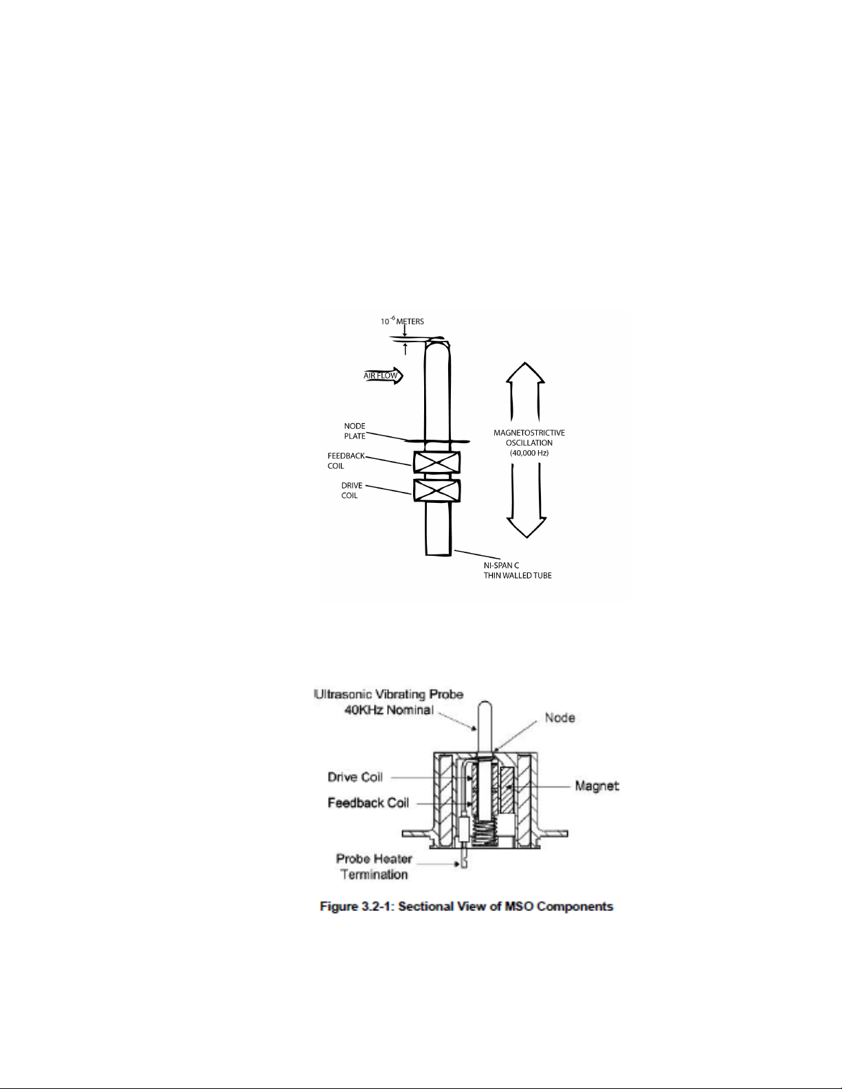
Section 3. Detailed Principle of Operation
The freezing rain sensor uses an ultrasonically axially vibrating probe to detect the presence of
icing conditions. The sensing probe is a nickel alloy tube mounted in the strut at its midpoint
(node) with one inch exposed to the elements. This tube exhibits magnetostrictive properties: it
expands and contracts under the influence of a variable magnetic field. A magnet mounted
inside the strut and modulated by a drive coil surrounding the lower half of the tube provides the
magnetic field.
A magnetostrictive oscillator (MSO) circuit is created with the above components and the
addition of a pickup coil and an electronic comparator. The ultrasonic axial movement of the
tube resulting from the activation of the drive coil causes a current to be induced in the pickup
coil. The current from the pickup coil drives the comparator that, in turn, provides the signal for
the drive coil.
The oscillation frequency of the circuit is determined by the natural resonant frequency of the
sensor tube, which is tuned to 40 kHz. With the start of an icing event, ice collects on the
sensing probe. The added mass of accreted ice causes the frequency of the sensing probe to
decrease in accordance with the laws of classical mechanics. A 0.020” (0.5 mm) thickness of ice
on the probe causes the operating frequency of the probe to decrease by approximately 130 Hz.
Freezing Rain Sensor software monitors probe frequency and detects and annunciates this
frequency decrease. At the same time, the internal probe heater power is applied until the
frequency rises to a predetermined set point plus an additional delay factor to assure complete
de-icing.
Note: by default, the heater power is not automatic and is controlled in the
programming of the sensor.
Page 4
4
Once de-iced, the sensing probe cools within a few seconds and is ready to sense ice
formation again. When ice forms on the sensing probe again to the point where the MSO
frequency decreases by 130 Hz, the sensor de-ices itself again. This cyclic process is
repeated if the freezing rain sensor remains in an icing environment. The ice signal
activates at 0.2 mm ice accretion and stays on until after the end of the icing encounter
through a manual trigger of the heater declared in the datalogger programming and will
remain on for 25 seconds. Each time 0.2 mm forms on the probe, the event count is
captured.
The Status output indicates whether the freezing rain sensor is functioning correctly
using tests that are described in more detail in following sections of this document.
Figure 1. MSO Circuit Schematic
Figure 2. MSO Circuit Sectional View
Page 5
5
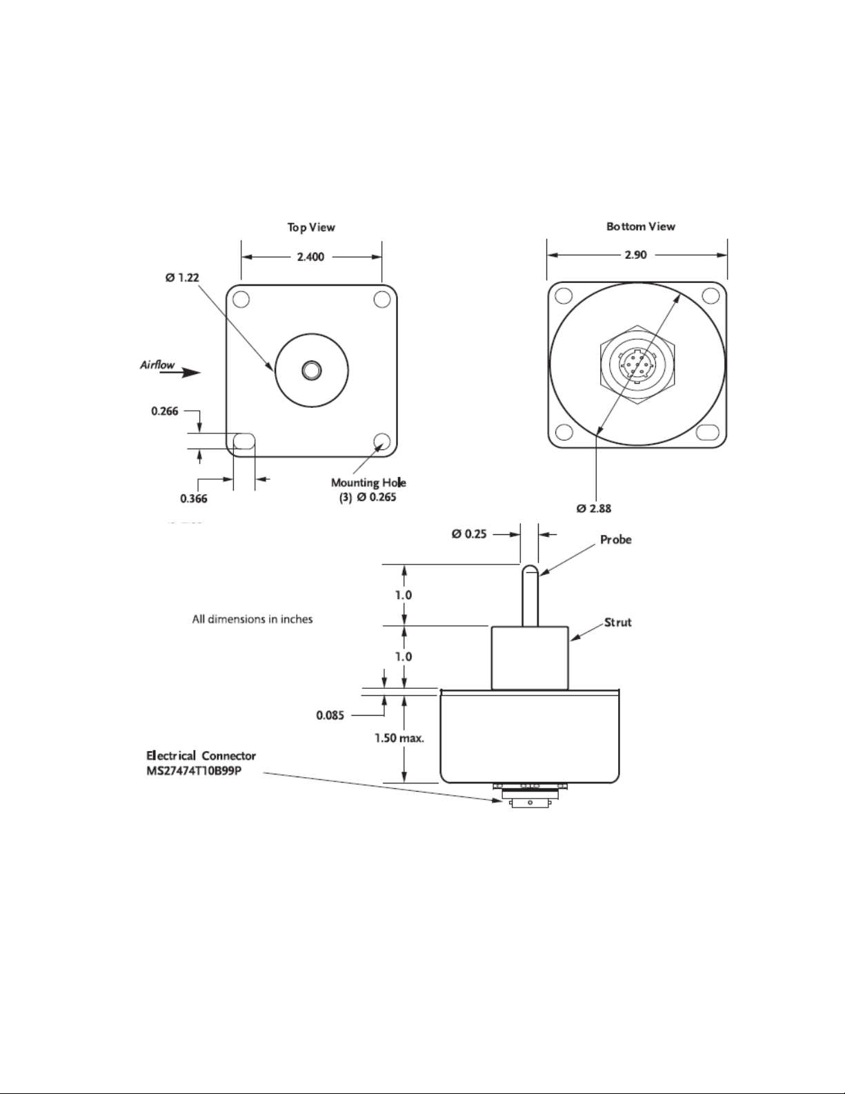
Section 4. Physical Description
The freezing rain sensor is an integrated unit containing both the sensor and processing
electronics. It contains a 2.9” (7.35 cm) square faceplate for mounting to the 0871LH1MNT and
a 2.86” (7.28 cm) diameter housing containing the processing electronics. It uses a
MS27474T10B99PN connector (MIL-C-38999, series II, jam nut), containing seven 20-gauge
pins. The unit weighs 0.7 lbs. (318 grams), maximum.
Figure 3. Physical Dimensions
Page 6
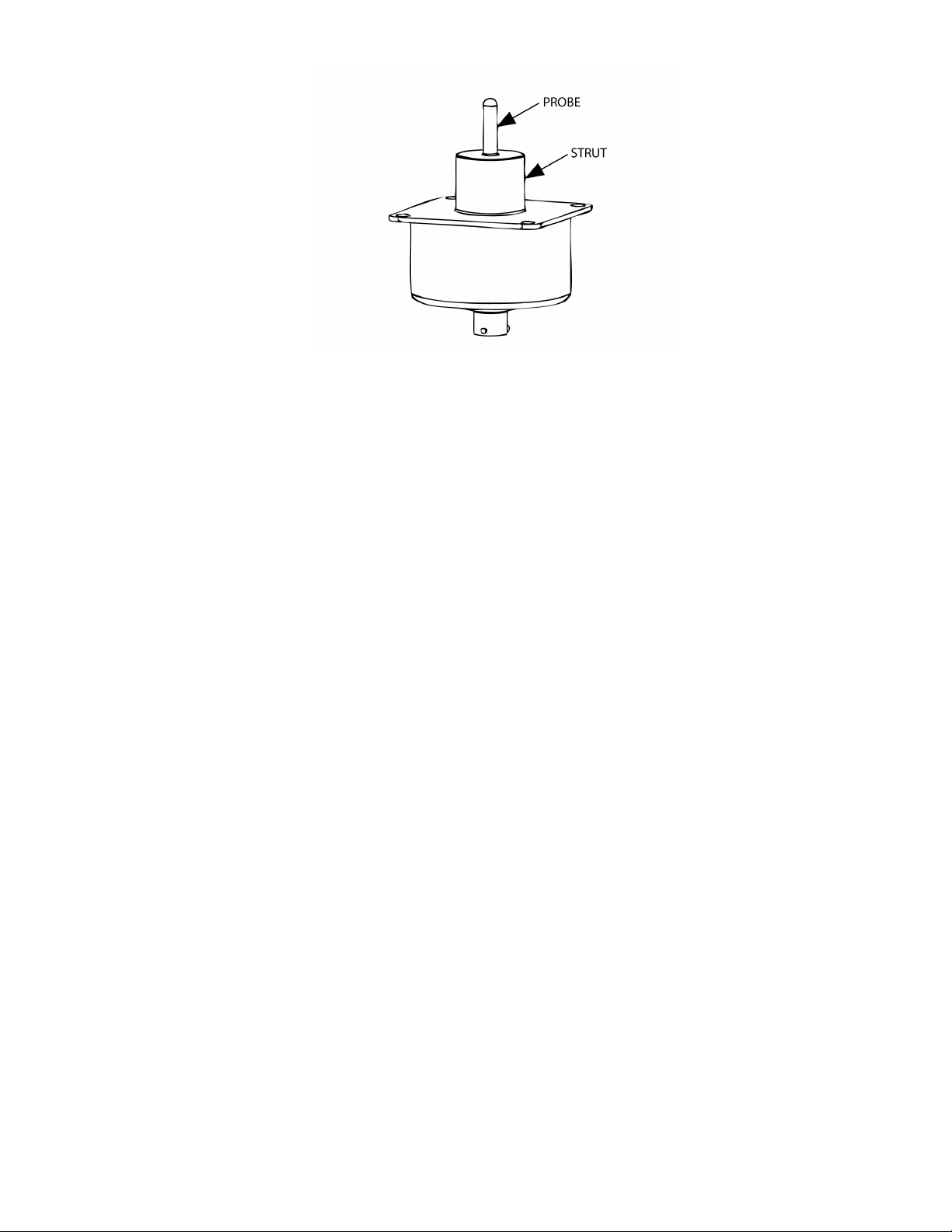
6
Figure 4. Ice Detector
Section 5. Temperature Considerations
In the case of unit malfunction causing strut heater lock-on, the probe temperature can exceed
204.4°C (400°F). Maintenance personnel should exercise caution when servicing the unit.
Section 6. Power Interruptions
The freezing rain sensor is qualified to DO-160C power input category Z. The unit will
remember status through a 200 ms power interruption, but the output string will cease during the
interruption.
The freezing rain sensor uses a power fail monitor to verify the supply voltage. If a power fault
is detected the freezing rain sensor is halted with a failure indication on the STATUS discrete
output.
6.1 Disconnection from Supply Source
The ice detector does not have an integrated power switch. The installation shall provide a
switch or circuit breaker near the ice detector, within easy reach of the operator,
and marked as the disconnecting device for the ice detector. The current rating for this switch
or circuit breaker should be at least 1.9 Amps but not greater than 5 Amps.
6.2 Protection Against Electric Shock – External Circuit Connections
All external circuits are contained in one connector (see Section 4), so are not accessible when
the unit and cable connectors are mated. Further, the operating voltages on all pins are
externally produced and externally limited to less than 33 V relative to 28 VDC Return, so are
not considered hazardous in normal or single fault conditions. All external circuits other than the
Case Ground pin shall be insulated from the Case Ground pin and unit enclosure according to
the dielectric and insulation requirements specified in Table 7-1.
Page 7
7
Section 7. Mounting Considerations
Description
Colour
CR1000X/CR1000
CR6
RS-485 High
White
Control Port*
U Port*
RS-485 Low
Brown
Control Port*
U Port*
Case GND
Green G G
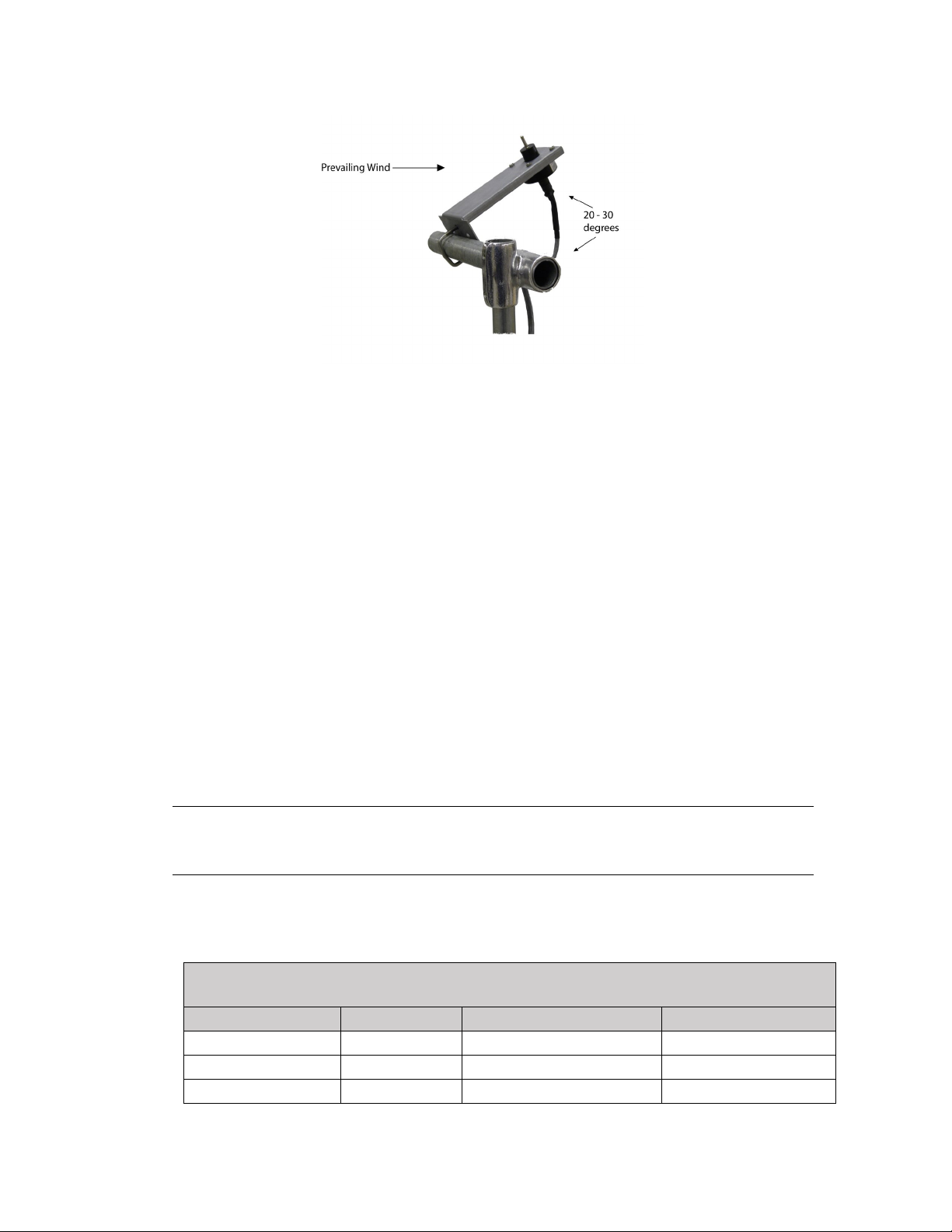
Figure 5. Mounting (part #0871LH1 MNT)
The freezing rain sensor should be mounted to a sturdy crossarm located away from buildings or
other obstacles that could shadow the sensing element from freezing rain. The sensor should be
installed so that the sensing probe is a minimum 36 inches above the ground.
1. Remove the protective tube from strut.
2. Attach the freezing rain sensor to the mounting bracket using the supplied ¼ - 20
screws and lock washers. Position the freezing rain sensor on the mounting pole with
the sensing probe pointing upward, with the bracket inclined at a 20° - 30° angle
above horizontal to ensure proper drainage of melted ice.
3. Attach to a vertical or horizontal pipe using the supplied V bolts, nuts and washers.
NOTE: The sensor should be mounted so as to be oriented into the prevailing wind.
4. Connect cable to connector.
5. Secure cable to bracket with cable ties.
6. Remove shipping cover and protective cap prior to powering on the unit.
NOTE: The "Hot Surface" safety label should be visible to the operator after the
equipment is installed. Otherwise, if the unit is installed fully enclosed, the mounting
apparatus should include the safety label in a visible location.
Section 8. Wiring Diagram - using cable Part # 0871LP1CBL-L
Table 1. Datalogger Connections
Page 8

8
24 VDC +
Red
V+
24 VDC -
Black
V-
*cannot share control ports
Table 2. Power Connections to C2673 (24VDC Power Supply)
‘
WARNING: Part C2673 must be installed by a certified electrician to local and national code.
Page 9

9
Section 9. Program Example
9.1 CR1000X
Ice detector 0871LP1 Sensor
'==================Sensors and Peripherals=====================
'Sensor: , Ice detector 0871LP1, Output type RS485 ,
' Polling Data' Baud rate: 9600, Data Bits: 8, Parity: None, Stop Bits: 1 The sensor will output Hex 24
Bytes string upon sending Command
' (S command to request current Satus and Command H to turn the heater ON)
'======================Wiring==============================
' --------- Ice detector 0871LP1 -------------------------' All external circuits other than the Case Ground pin shall be insulated from the Case Ground pin and
unit enclosure.
' RS485 port in the sensor:
' C5 ----------------------------- Brown (PIN E) RS-485 Low
' C6 ----------------------------- WHITE (PIN D) RS-485 High
' 24 V Power ---------------------Red (PIN A)
' Power Return ------------------ BLACK (PIN B)
' Earth Ground ------------------ Green ( PIN C)
'=======================Constants=========================
'Start of Constants Customization Section
'Program Scan Rate
Const Scan_Rate = 5
' Ice thickness in mm
Const Ice_mm_Threshold = 0.2
'End of Constants Customization Section
'====================== Declarations========================
'Diagnostic Parameters
Public Battery_Voltage
Units Battery_Voltage = Volts
Public Panel_Temperature
Units Panel_Temperature =Deg C
'0871LP1 Parameters
Public Read_LP1 As Boolean
Public Ice
Units Ice = inches
Public Ice_mm
Units Ice_mm = mm
Public Ice_Event_Count As Long
Public LP1_Serial_Error As Boolean
Dim LP1_Bytes(24) As Long
Public LP1_String(24)As String
Public LP1_Probe_Heater_State As String *3
Public LP1_Ice_Output As String *6
Page 10

10
Public LP1_status_Output As String *4
' ERRSTAT1 Parameters
Public LP1_ERR_MSO_TOO_HIGH As String *4
Public LP1_ERR_MSO_TOO_LOW As String *4
Public LP1_ERR_EEPROM As String *4
Public LP1_ERR_RAM As String *4
Public LP1_ERR_ROM As String *4
Public LP1_ERR_WATCHDOG As String *4
Public LP1_ERR_PWR_INT_TIMER As String *4
' ERRSTAT2 Parameters
Public LP1_ERR_DE_ICING As String *4
Public LP1_ERR_PROBE_HEATER As String *4
Public Frequency As Float
Units Frequency = Hz
Public LP1_ON_Time_Days As Float
Public LP1_Cold_Start_Count As Float
Public LP1_ICE_Count As Float
Public LP1_FAIL_Count As Float
Public LP1_MSO_FAIL_Count As Float
Public LP1_Heater_FAIL_Count As Float
Public LP1_Software_Version As Float
Public LP1_ICE_Count_From_PWR_ON As Float
Public LP1_CHECKSUM As Float
'====================== Data Tables=========================
'Diagnostics Data Table (should be collected on a daily basis)
DataTable(Diagnostics,True,365)
DataInterval(0,1440,Min,0)
CardOut(0,365)
Maximum(1,Battery_Voltage,FP2,False,False)
Minimum(1,Battery_Voltage,FP2,False,False)
Maximum(1,Panel_Temperature,FP2,False,False)
Minimum(1,Panel_Temperature,FP2,False,False)
Sample(1,Status.OSVersion,String)
Sample(1,Status.SerialNumber,UINT2)
Sample(1,Status.StartTime,String)
Sample(1,Status.StationName,String)
Sample (1,Status.ProgName,String)
Sample(1,Status.RunSignature,UINT2)
Sample(1,Status.ProgSignature,UINT2)
Sample(1,Status.LithiumBattery,UINT2)
Sample(1,Status.Low12VCount,UINT2)
Sample(1,Status.SkippedScan,UINT2)
Sample (1,Status.WatchdogErrors,UINT2)
Sample (1,Status.VarOutOfBound,UINT2)
Sample(1,Status.CPUDriveFree,UINT4)
Page 11

11
Sample(1,Status.USRDriveFree,UINT4)
Sample(1,Status.CardBytesFree,UINT4)
EndTable
DataTable(Table1,True,-1)
DataInterval(0,60,Min,10)
Minimum(1,Battery_Voltage,FP2,False,False)
Average(1,Panel_Temperature,FP2,False)
EndTable
DataTable(LP1_Ice_Detector,True,-1)
Sample (1,LP1_Raw_in_Buff,String)
Sample (1,Frequency,IEEE4)
Sample (1,Ice_Event_Count,IEEE4)
Sample (1,Ice_mm,FP2)
Sample (1,LP1_Ice_Output,String)
Sample (1,LP1_status_Output,String)
Sample (1,LP1_Probe_Heater_State,String)
Sample (1,LP1_ERR_MSO_TOO_HIGH,String)
Sample (1,LP1_ERR_MSO_TOO_LOW,String)
Sample (1,LP1_ERR_EEPROM,String)
Sample (1,LP1_ERR_RAM,String)
Sample (1,LP1_ERR_ROM,String)
Sample (1,LP1_ERR_WATCHDOG,String)
Sample (1,LP1_ERR_PWR_INT_TIMER,String)
Sample (1,LP1_ERR_DE_ICING,String)
Sample (1,LP1_ERR_PROBE_HEATER,String)
Sample (24,LP1_Bytes(),FP2)
Sample (1,LP1_CHECKSUM,FP2)
EndTable
'====================== Subroutines=========================
' Error State Subroutine
Sub LP1_Error_State
LP1_Probe_Heater_State = "NAN"
LP1_Ice_Output = "NAN"
LP1_status_Output ="NAN"
LP1_ERR_MSO_TOO_HIGH ="NAN"
LP1_ERR_MSO_TOO_LOW ="NAN"
LP1_ERR_EEPROM ="NAN"
LP1_ERR_RAM ="NAN"
LP1_ERR_ROM ="NAN"
LP1_ERR_WATCHDOG ="NAN"
LP1_ERR_PWR_INT_TIMER ="NAN"
LP1_ERR_DE_ICING="NAN"
LP1_ERR_PROBE_HEATER ="NAN"
Frequency = NAN
Page 12

12
LP1_ON_Time_Days = NAN
LP1_Cold_Start_Count =NAN
LP1_ICE_Count =NAN
LP1_FAIL_Count =NAN
LP1_MSO_FAIL_Count =NAN
LP1_Heater_FAIL_Count =NAN
LP1_Software_Version =NAN
LP1_ICE_Count_From_PWR_ON =NAN
LP1_CHECKSUM =NAN
EndSub
' Get Data Subroutine
Sub LP1_GetData
Public LP1_Raw_in_Buff As String *48
Public String_Length
Public i,J
Public NBytesReturned
LP1_Serial_Error = False
If LP1_Serial_Error = False
SerialFlush (ComC5)
SerialOut (ComC5,"S",CHR(13),0,10)
Delay (1,200,mSec)
SerialInRecord (ComC5,LP1_Raw_in_Buff,0,48,&H0D0A,NBytesReturned,01)
String_Length = Len (LP1_Raw_in_Buff)
J=0
For i = 1 To 24
LP1_String(i)=Mid (LP1_Raw_in_Buff,1+J,2)
J=J+2
Next i
EndIf
LP1_CHECKSUM = 0
For i = 1 To 24 Step 1
LP1_Bytes(i)= HexToDec(LP1_String(i))
If i < 24
LP1_CHECKSUM = LP1_CHECKSUM+ LP1_Bytes(i)
EndIf
Next
LP1_CHECKSUM=LP1_CHECKSUM AND &B11111111
If LP1_CHECKSUM <> LP1_Bytes(24)Then LP1_Serial_Error = True
If LP1_Serial_Error = True Then
Call LP1_Error_State
Else
' For LP1 Byte 1
' Bit 0 -Status Output
If (LP1_Bytes(1) AND &B00000001) <> 0 Then
LP1_status_Output = "Fail"
Page 13

13
Else
LP1_status_Output = "OK"
EndIf
' Bit 1 -Ice Output
' **The discrete Ice signal output is non-functional in the LP1 model, no external connection
is required**
If (LP1_Bytes(1) AND &B00000010) <> 0 Then
LP1_Ice_Output = "Ice"
Else
LP1_Ice_Output = "No Ice"
EndIf
' Bit 2 - Probe Heater State
If (LP1_Bytes(1) AND &B00000100) <> 0 Then
LP1_Probe_Heater_State= "On"
Else
LP1_Probe_Heater_State= "Off"
EndIf
' Bytes 2 and 3 concatenation for the MSO frequency
Frequency = 774060000/((LP1_Bytes(2) << 8)+ LP1_Bytes(3))
' Byte 4 is the ERRSTAT1
If (LP1_Bytes(4) AND &B00000001) <> 0 Then
LP1_ERR_PWR_INT_TIMER = "Fail"
Else
LP1_ERR_PWR_INT_TIMER = "OK"
EndIf
If (LP1_Bytes(4) AND &B00000010) <> 0 Then
LP1_ERR_WATCHDOG= "Fail"
Else
LP1_ERR_WATCHDOG = "OK"
EndIf
If (LP1_Bytes(4) AND &B00000100) <> 0 Then
LP1_ERR_ROM= "Fail"
Else
LP1_ERR_ROM = "OK"
EndIf
If (LP1_Bytes(4) AND &B00001000) <> 0 Then
LP1_ERR_RAM= "Fail"
Else
LP1_ERR_RAM = "OK"
EndIf
If (LP1_Bytes(4) AND &B00010000) <> 0 Then
LP1_ERR_EEPROM= "Fail"
Else
Page 14

14
LP1_ERR_EEPROM = "OK"
EndIf
If (LP1_Bytes(4) AND &B00100000) <> 0 Then
LP1_ERR_MSO_TOO_LOW= "Fail"
Else
LP1_ERR_MSO_TOO_LOW = "OK"
EndIf
If (LP1_Bytes(4) AND &B01000000) <> 0 Then
LP1_ERR_MSO_TOO_HIGH= "Fail"
Else
LP1_ERR_MSO_TOO_HIGH= "OK"
EndIf
' Byte 5 is the ERRSTAT2
If (LP1_Bytes(5) AND &B11000000) = &B00000000 Then
LP1_ERR_PROBE_HEATER= "OK"
ElseIf (LP1_Bytes(5) AND &B11000000) = &B01000000 Then
LP1_ERR_PROBE_HEATER= "Always On"
ElseIf (LP1_Bytes(5) AND &B11000000) = &B10000000 Then
LP1_ERR_PROBE_HEATER= "Always Off"
ElseIf (LP1_Bytes(5) AND &B11000000) = &B11000000 Then
LP1_ERR_PROBE_HEATER= "On"
EndIf
If (LP1_Bytes(5) AND &B00100000) <> 0 Then
LP1_ERR_DE_ICING= "Fail"
Else
LP1_ERR_DE_ICING= "OK"
EndIf
' LP1 output ON in 10 Minute Increments
LP1_ON_Time_Days = ((LP1_Bytes(6)<< 16 )+(LP1_Bytes(7)<<8)+LP1_Bytes(8))/144
' Cold Start Power-On Count
LP1_Cold_Start_Count = (LP1_Bytes(9)<<8)+LP1_Bytes(10)
' Ice Event
' Ice Count Bit won't update in this model LP1. It will be always Zero
LP1_ICE_Count = (LP1_Bytes(11)<<8)+ LP1_Bytes(12)
LP1_FAIL_Count = LP1_Bytes(13)
' MSO frequency Fail Count
LP1_MSO_FAIL_Count = LP1_Bytes(14) >> 4
' Heater Fail Count
LP1_Heater_FAIL_Count = LP1_Bytes(14) AND &B00001111
' Software Version
LP1_Software_Version = LP1_Bytes(22)
' Correlation Count
Page 15

15
LP1_ICE_Count_From_PWR_ON = LP1_Bytes(23)
EndIf
EndSub
SequentialMode
'=======================Main Program======================
BeginProg
'Open port COMC5 for the 0871LP1 Ice Sensor
SerialOpen (ComC5,9600,3,0,50,4)
'=======================Main Scan=========================
Scan(Scan_Rate,Sec,1,0) 'scan rate is set as a constant
'===================Diagnostics Information====================
'Datalogger Battery Voltage measurement
Battery(Battery_Voltage)
'Wiring Panel Temperature measurement
PanelTemp(Panel_Temperature,_60Hz)
Read_LP1 = true
If Read_LP1 = true
Call LP1_GetData
Read_LP1 = false
EndIf
' Formula to convert the frequency into Ice Thickness (inches)
Ice = -0.00015*Frequency + 6
If Ice < 0 Then Ice = 0
' Convert the accumulation from inches to Millimimeters
Ice_mm = Ice*25.4
' If the Ice > Ice_mm_Threshold turn the heater ON
If Ice_mm > Ice_mm_Threshold
Read_LP1 = false
SerialFlush (ComC5)
' Turn the heater ON if the Ice accumulation is above the threshold
SerialOut (ComC5,"H","",0,100)
' Increment the Ice_Event_Count every time the heater turns ON
Ice_Event_Count = Ice_Event_Count +1
EndIf
'=====================Call Data Tables=======================
CallTable (LP1_Ice_Detector)
CallTable Table1
CallTable (Diagnostics)
' Reset the Ice_Event_Count counter at midnight
If TimeIntoInterval (0,1440,Min) Then Ice_Event_Count = 0
NextScan
Page 16

16
Section 10. RS-485 Output Format for non-Campbell Datalogger
Request Code
Description
“T” or “t”
Request self test
“S” or “s”
Request current status information
“H” or “h”
Request Heater Activation
Applications
A two-line output provides a bi-directional serial port, running at 9600 BAUD (8-bits, one
Start Bit, One Stop Bit, no parity), to allow communication with aircraft electronics and
external test equipment.
10.1 Valid Request Codes
All communications are initiated by the external serial communications program. Table 3
lists the valid request commands, which are single ASCII characters. Each character
should be sent at least 100 ms apart. If commands are not spaced at 100 ms, they may be
ignored.
To identify the beginning of a response string from the ice detector (presently only
required for command “S”), a leading ASCII character is transmitted. To identify the end
of the response string, a carriage return and line feed are transmitted. All responses will
be transmitted in ASCII format.
Table 3. Valid Request Codes
Command “T” – Request a Self Test:
If an ASCII “T” or “t” is sent to the ice detector, the ice detector will run a self test. The
results of the self test can be retrieved by requesting the current status information.
Command “S” – Request for Status Information:
If an ASCII “S” or “s” is sent to the ice detector, the ice detector will respond with the
data string described in Table 5 under Section 12. The response will be transmitted in an
ASCII format but will represent hexadecimal values. In this document, hexadecimal
values are denoted by a “0x” followed by the value.
Command “H” – Request Heater Activation:
The probe heater is activated by sending an ASCII “H” or “h” to the ice detector after a
predetermined icing trip point is reached, as indicated by the Ice Output bit or MSO
frequency in the serial data string (see Table 5). The ice detector turns off the heater five
seconds after the MSO has returned to at least 39,970 Hz (the additional five seconds
allows the probe time to shed the de-bonded ice). The maximum heater ON time is 25
seconds. If the probe frequency has not returned to at least 39,970 Hz by that time, a deice failure is declared, and the heater is turned off. The ice detector will not accept any
Page 17

17
other commands while the heaters are active. See section 15.5 for other information about
the heater and control/feedback function.
Section 11. Built-In-Test (BIT)
Built-In-Test (BIT) capabilities of the freezing rain sensor consist of hardware, continuous,
power-up, and operator-initiated tests.
Whenever a failure is detected and verified, the freezing rain sensor stops detecting and
annunciating icing conditions and the heaters are disabled. Failures detected in Initiated and
Continuous BIT are counted and enunciated once they have been verified. To eliminate
nuisance errors, failures are verified by delaying (debouncing) the failure for a period of
time. Failures detected in Initiated BIT are latched and power must be cycled on and off to
remove a failure. If failures detected in Continuous BIT go away, the ice detector changes
back to normal mode, and once again enables all ice detection functions.
11.1 Hardware Built-In-Test (BIT)
Hardware BIT is comprised of a watchdog timer that forces the microcontroller to reinitialize if it does not receive a strobe every 1.6 seconds. An internal voltage monitor forces
the microcontroller to the reset state if the internal 5VDC power supply falls below 4.65
VDC and holds it there until the power supply returns above 4.65 VDC. When the
microcontroller is reset, no output string is sent.
11.2 Continuous Built-In-Test (BIT)
Continuous BIT consists of verifying the following:
• The probe heater is in the correct state. The return leg of the heater is monitored.
• The ICE discrete output is in the correct state. The ICE discrete output is fed back to
the microcontroller through a passive voltage divider and voltage comparator.
• The MSO is operating correctly. Frequencies between 39000 and 40150 Hz are
valid.
• The probe heater is de-icing correctly. After turn-on, the probe heater must cause the
MSO frequency to return to at least 39970 Hz within the 25 second timeout or it is
considered failed.
• Probe is de-iced within 25 seconds. (De-Icing Fail).
Page 18

18
11.3 BIT Failure That Disables Ice Output
Title
MSO Fail, High
MSO Fail, Low
EEPROM Fail
RAM Fail
ROM Fail
Watchdog Fail
Power Interrupt Timer Fail
Power Fault Monitor Fail
Probe Heater Always ON or OPEN
Probe Heater Always OFF
Probe Heater ON w/ 1 Enable
De-Icing Fail
Unknown Reset Failure
The Ice output is disabled due to Continuous and Initiated BIT failures as shown in Table 4.
BIT Information. Ice detection is disabled when these failures occur because the integrity of the
ice detection capability has been compromised.
Table 4. BIT Information
Disable Ice
Detection 1
X X
X X
X
X X
X X
X
X
X
Active Test3 Passive Test4
Active Test3 Passive Test2
X
Clear Only Set Only
X
Initiated
BIT
Continuous
BIT
Note: When the failure is enunciated, the software no longer provides ice detection capability.
Note: In Continuous BIT, the “Probe Heater Always OFF” failure is set when the heater is ON and a deicing failure has been detected. If the frequency indicates that the ice has been removed within the
expected time, the software will not annunciate the probe heater failure. The actual failure is most likely
due to a problem in the heater feedback circuitry rather than heater control circuitry. The failure will be
enunciated the next time IBIT is performed.
Note: Active test means actual triggering of the function in all states to verify response of the freezing rain
sensor
Note: Passive test means a status check/verification that the function is in the state command
Page 19

19
11.4 Operator-Initiated Tests
The operator can test the freezing rain sensor functionality by squeezing the tip of the probe
between the index finger and thumb. This simulates icing by decreasing the frequency of the
probe.
With the sensor wired to the datalogger use a digital voltmeter (DVM); measure DC voltage
signal between the Ice signal (blue wire in control port) and the power reference ground (black
wire in G terminal). The voltage reading should be 4500mvDC to 5000mvDC. When the probe
tip of the ice detector is squeezed; thus changing the frequency and tripping the probe, the
voltage reading will immediately drop to a reading below 500mvDC. Observing this will verify
that the probe is operating properly and give the user enough time to release the probe before it
reaches its full heating temperature.
Caution: Once initiated, the heating (de-icing) sequence will quickly heat the probe to
204.4°C. Though bare fingers must be used for a reliable test result, there is a danger that
you will burn your fingers if you do not let go when heating has been verified.
11.5 Initiated Built-In-Test (BIT)
Initiated BIT is performed at initial power-up of the freezing rain sensor and following
power interruptions of not less than 200 ms. Initiated BIT consists of the following tests:
• The ice and fault status outputs are set in the RS-485 string and on the discrete
outputs so monitoring electronics or test equipment can verify activation.
• The freezing rain sensor heater is turned on for a short period of time to verify
correct operation of the heater, heater control circuit, and heater feedback circuit.
• Correct operation of the watchdog timer is verified by simulating a
microcontroller time-out and waiting for a reset input.
• Proper ROM operation is verified by computing a checksum of the ROM
contents and comparing against a checksum stored in the ROM.
• RAM operation is verified by writing and reading test bytes.
• The Power Interrupt Timer is checked by verifying its transitions to a “warm”
state after performing a “cold” start.
• The power fail input is pulled down to verify a power failure is detected.
• Each time the critical data from the Serial EEPROM is read, a checksum is read
and compared to the checksum computed from the contents. Each time critical
Page 20

20
data is written to the Serial EEPROM, a checksum is computed and stored with
the data.
• Resets due to unknown reasons (such as reset from the watchdog timer) are
detected.
Initiated BIT will examine the RESET EEPROM input. If the input is active, the STATUS
output will be set to FAIL and the ICE output and probe heater will be disabled. (This feature
allows a factory technician to perform the MSO capacitor selection process without activation
of the probe heater.)
Activation of the Press-to-Test (PTT) input for greater than 100 ms also causes the ice detector
to perform Initiated BIT. The PTT input is ignored when the ice output is active. After PTT is
completed, the correlation count is restored to its pre-test value.
Initiated BIT is complete within 3 ± seconds of initial power up.
Section 12. Correlation Counting
The freezing rain sensor tracks the amount of ice accumulation on the probe during an icing
encounter. The correlation count is a value tracked by the freezing rain sensor that indicates the
amount of ice that has accumulated on the probe during the icing encounter. Each correlation
count equals 0.010 inches of ice.
The correlation count, ranging from 0 to 255, indicates the number of times the MSO
frequency decreases by 65 Hz during an icing encounter. A decrease in frequency of 65 Hz
correlates to an equivalent 0.25 mm of ice that would have formed on the ice detector probe,
neglecting the change in collection efficiency caused by ice build-up. Upon reaching a
correlation count of 255, the value is no longer incremented.
The freezing rain sensor compensates by adding a value (ranging from 0 to 6) to the correlation
count when the ice detection cycle is completed, to account for the ice that would have
accumulated if the heater had not been on.
The correlation count is in the serial string, Table 5. Serial String Format.
The correlation count is initialized to zero at unit power up.
Section 13. Electrostatic Discharge (ESD) Consideration
The freezing rain sensor internal components are ESD sensitive, class 1, so proper ESD
precautions must be observed (wrist straps, conductive surfaces) when handling.
Page 21

21
Section 14. Ice Detector RS-485 String Format
Byte
Bit
Definition
Comments/Interpretation/Range
0 (First)
7 (MSB)
String ID
Presently defined as 00
6
May add additional strings in
future 5 - 3
Unused
2
Probe Heater State
1- Heater On
0- Heater Off
1
Ice Output
1- Ice
0- No Ice
0 Status Output
1- Fail
0- (OK) No Fail
1 -2 MSO FREQUENCY
MSO Count in Hex
Frequency = 774060000/Dec
(MSO)
3 - ERRSTAT1
7
Unused
1 = Active
6 MSO Fail, Too High
5 MSO Fail, Too Low
4 EEPROM Fail
3 RAM Fail
2 ROM Fail
1 Watchdog Fail
0 Power Interrupt Timer Fail
4 - ERRSTAT2
7 - 6
Probe Heater Failure
00 = Probe Heater OK
01 = Probe Heater Always ON
or OPEN
10 = Probe Heater Always OFF
11 = Probe Heater ON with 1
Enable 5
De-Icing Fail
1 = Active
4 Unused
3 Unused
2 Unused
Table 5. Serial String Format
Page 22

22
1 Unused
0 Unused
5 - 7 ON-TIME CNT
Power-On Time (In Hex) in 10-Minute Increments
00 - 01FFFF
8 - 9 COLD START CNT
Cold Start Power-On Count
00 - FFFF
10-11 ICE CNT
Ice Events
00 - FFFF
12 - FAIL CNT
Total Failures Encountered. This number is
incremented each time the ice detector transitions
00 - FF
13 - FAIL DTL 1
7 - 4
MSO Frequency Fail Count
0 - F 3 - 0
Heater Fail Count
0 - F
14 - FAIL DTL 2
7 - 4
Not Used
Not Used
3 - 0
Not Used
Not Used
15 - LAST ERR 1
See ERRSTAT1 Above
16 - LAST ERR 2
See ERRSTAT2 Above
17 - 2ND LAST ERR 1
See ERRSTAT1 Above
18 - 2ND LAST ERR 2
See ERRSTAT2 Above
19 - PERM ERR 1
See ERRSTAT1 Above
20 - PERM ERR 2
See ERRSTAT2 Above
21 - Software Version
7 - 0
Software Version per VDD/SC1
0 - FF
22 - Correlation Count
7-0
0.01" ice accretion increments since power-on
0 - FF
23 - CHECKSUM
Summation (1-byte wide) of bytes 0 - 22
0 - FF
from OK to fail.
Page 23

23
Section 15. Functionality Descriptions
15.1 Microcontroller
The freezing rain sensor uses an Intel 87C51-type microcontroller to control the freezing rain
sensor functions. This 8-bit microcontroller requires at least: 4 Kbytes of on-board ROM,
128 bytes of RAM, and 32 input/output ports. The freezing rain sensor uses about 75% of
these resources. Upgraded microcontrollers that provide more resources are available. The
microcontroller runs at 7.372 MHz.
15.2 Watchdog/Reset Circuit
The watchdog timer/reset circuit monitors the microcontroller and provides a reset pulse if
not periodically toggled. The watchdog also provides reset pulses on initial power-up and
holds the microcontroller in the reset state if the internal power supply falls below an
acceptable voltage. The watchdog indicates impending power loss so the ice detector can
shut down in a known manner.
15.3 Serial EEPROM
The Serial EEPROM stores unit status (icing state, failure state, heater state, correlation
count) which is recovered after power interruptions of 200 ms or less. This allows the unit to
meet the power interruption requirements of RTCA DC-160C, Section 16, Category Z.
Additionally, the Serial EEPROM stores environmental and failure information such as unit
elapsed-time, number of icing encounters, number of failures, and detailed information on
types and quantities of each annunciated failure. This information is used by Collins
Aerospace to confirm and repair failures reported by the end user and to collect MTBF data.
Each time the Serial EEPROM is written, a checksum is computed and written. Each time the
Serial EEPROM is read, a checksum is computed and compared to the stored value.
15.4 Probe Oscillator
The probe oscillator is the electronic control portion of the magnetostrictive oscillator (MSO)
used to sense and detect ice. This circuit provides the drive and feedback of the ice sensing
probe. The circuit drives the probe at a nominal 40kHz and converts the feedback into a
CMOS compatible square wave that is measured by the microcontroller. As ice accretes on
the probe, the frequency decreases, and it is this frequency change that the microcontroller
annunciates in the form of Ice Signal #1.
Page 24

24
15.5 Heater and Heater Control
The probe heater de-ices the probe. It is activated when the nominal icing trip point of 0.020” is
reached and is turned off five seconds after the MSO has returned to at least 39,970 Hz (the
additional five seconds allows the strut probe time to shed the de-bonded ice). The maximum
heater ON time is 25 seconds. If the probe frequency has not returned at least 39,970 Hz by that
time, a de-ice failure is declared, and the heaters are turned off. An open circuit of the heater is
detected by the microcontroller.
The probe heater is activated by sending an ASCII “H” or “h” to the ice detector after a
predetermined icing trip point is reached, as indicated by the Ice Output bit or MSO frequency in
the serial data string (see Table 5). The ice detector turns off the heater five seconds after
the MSO has returned to at least 39,970 Hz (the additional five seconds allows the probe time to
shed the de-bonded ice). The maximum heater ON time is 25 seconds. If the probe frequency
has not returned to at least 39,970 Hz by that time, a de-ice failure is declared and the heater is
turned off. The ice detector will not accept any other commands while the heaters are active.
The probe heater de-ices the probe. The heater control turns the probe heater ON as
commanded by the external serial communications program and OFF as
commanded by the microcontroller (embedded software). Two outputs are required from the
microcontroller to turn on the heater. This minimizes the possibility of an unintended heater ON
condition. The heater control also monitors the state of the heater and provides feedback to the
microcontroller so that it can be determined whether the heater is on, off or open circuit
15.6 Drive and Feedback Coil
The drive coil modulates the magnetic field of the magnetostrictive oscillator and causes an
ultrasonic axial movement of the probe.
The feedback coil senses the movement of the probe and when employed in the probe oscillator
circuit, completes the feedback portion of the MSO.
15.7 DC Power Supply
The DC power supply provides 24 VDC for the heater circuitry. Internal circuitry converts the
24 VDC input power to 5 VDC for use by the microcontroller and associated circuits. It employs
a large input capacitor to provide enough time between detection of input power loss and actual
loss of DC power, for the microcontroller to store the current unity status in the non-volatile
memory. The DC power supply provides input transient protection to meet RTCA DO-160C
power input, voltage spike, and lightning requirements.
Page 25

25
15.8 Status Output
The status output provides a ground output when the freezing rain sensor is operating
correctly, and high impedance (200 KΩ minimum) when the unit has detected a failure.
Failures are detected through continuous and initiated tests. The Status output can sink 50
mA and is guaranteed to be no more than 1.5 VDC with respect to Signal Return when
active. This output is transient protected to meet RTCA DO-160C lightning requirements and
to prevent stray high-voltage from coupling into the unit and damaging the output transistor.
15.9 Ice Signal Output
The Ice Signal output provides a ground output for 60 ± 6 seconds when the ice detector has
detected the presence of ice (frequency drop of 130 Hz, equivalent to approximately 0.020”
ice formation). If the frequency subsequently decreases by 130 Hz while the Ice Signal
output timer is non-zero, the timer is reinitialized to 60 seconds.
The output is transient protected to meet RTCA DO-160C lightning requirements and to
prevent stray high-voltage from coupling into the unit and damaging the output transistor.
The ice output has feedback to the microcontroller for software to verify it is in the correct
state for more built in test coverage. The software in the 0871LH1 model uses this feedback
to verify that the ice output is operating correctly. However, in the 0871LP1 model, the
software does not use this input.
Page 26
26
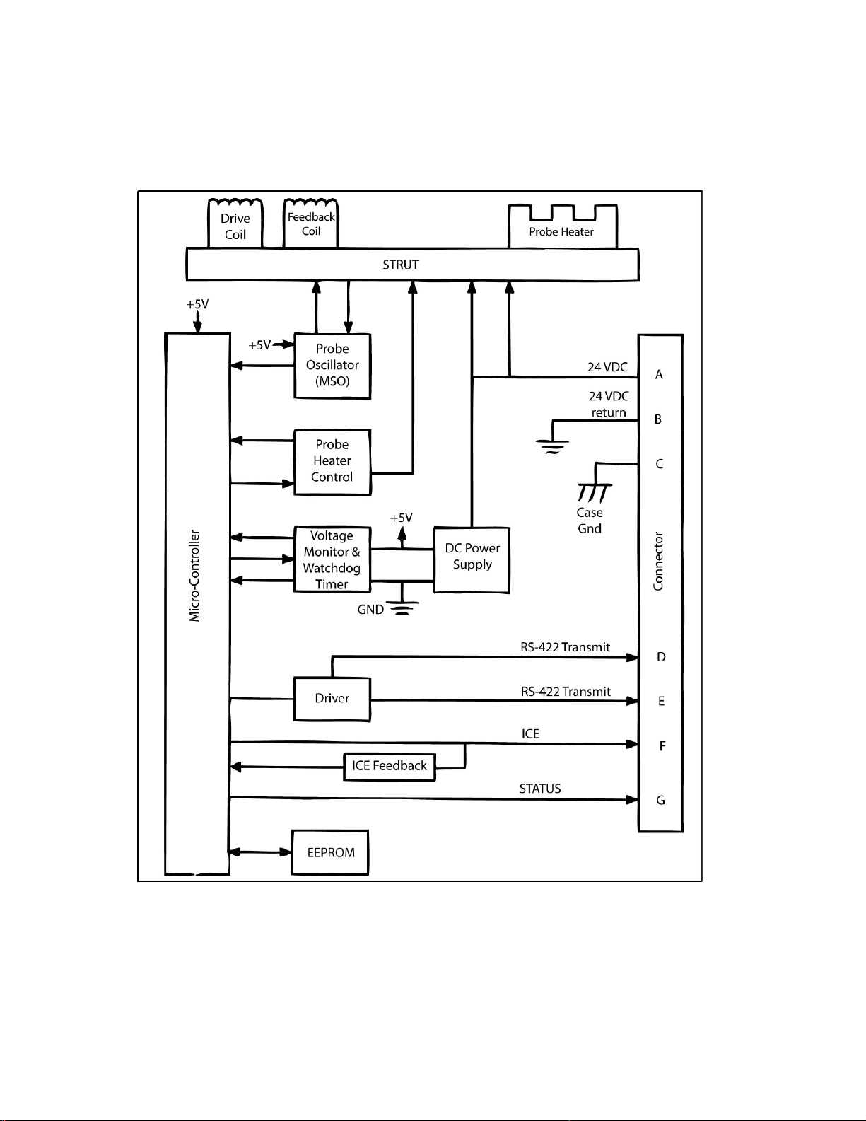
Appendix A Freezing Rain Sensor Block Diagram
The block diagram provides an understanding of the functionality of the freezing rain sensor.
Figure 6 Functional Block Diagram
Page 27

27
Appendix B. Input/Output Pin Designations
Signal Name
Con-
Pin
Input or
Definition
Current
Wire
Input
18-29.5 VDC**
1.5 Amp Max at
28VDC
20
Input
----
1.5 Amp Max
20
Case Ground
C
Input
----
----
20
RS-485 High
D
Output
Per TIA-485-A Spec
Per TIA-485-A
20-24
RS-485 Low
E
Output
Per TIA-485-A Spec
Per TIA-485-A
20-24
Output
Non-Functional, no connection
require***
Open Inactive
Output
Ground Active (1.5 VDC Max)
[OK]
0.5 - 50 mA
20-24
Open Inactive [Unit Failed]
Table 6. Input/Output Pin Designations
nector
24VDC A
24VDC Return B
Ice F
Status G
**Ice will be correctly detected between these voltages. Proper probe de-icing, however, is only guaranteed when
input voltage is 24VDC or greater.
*** Toggles +5V/ground during PBIT but does not annunciate ice.
Output
Gauge
Page 28

28
Appendix C Qualification Capabilities
Test Name
Test Requirement
EMC
DO-160C:
Audio Freq
Susc:
Cat Z
Induced Signal:
Cat Z
Susc:
Chg Notice 3, Cat R
RF
Susceptibility:
Cat R
RF Emissions:
Cat Z
Lightning Induced Susceptibility
DO-160C:
Multiple Burst:
Waveform 3 & 4: Level 3
Multiple Stroke:
Waveform 3: Level 3
Temperature Variation
DO-160C:
Cat B
Temperature/Altitude
DO-160C:
Cat D2 (-40°C to +71°C)
Vibration
DO-160C:
Cat E and L(Random, 7.9
grms)
Operation Shock, Crash Safety
DO-160C:
Shock
Salt Spray
DO-160C:
Cat S
Humidity
DO-160C:
Cat B
Icing Performance
Collins Aerospace, Inc. Test Procedure
Power Input
DO-160C:
Cat Z, 18 - 29.5 VDC
Voltage Spike
DO-160C:
Cat A
Magnetic Effect
DO-160C:
Cat A (1 deflection at 0.5m)
Bonding
2.5 mΩ Max. Mounting Plate to Aircraft Structure
10 mΩ Max. Connector Shell to Mounting Plate
Dielectric Withstanding
MIL-STD 202, 500 VAC, 60 Hz, EMI Filters
Disconnected
Insulation Resistance
MIL-STD 202, 500 VDC, 1000 MΩ, EMI Filters
Disconnected
Fluid Susceptibility
DO-160C:
Cat F
Waterproofness
DO-160C:
Cat W
Fungus Resistance
DO-160C:
Cat F
Sand and Dust
DO-160C:
Cat D
Direct Lightning Strike
DO-160C:
Cat 1A
Software
DO-178B used as a guideline
Table 7. Qualification Capability Levels
 Loading...