

Page 1

Model 083E Relative Humidity
and Temperature Sensor
6/12
Copyright © 2012
Campbell Scientific, Inc.
Page 2

Page 3

Warranty
“PRODUCTS MANUFACTURED BY CAMPBELL SCIENTIFIC, INC. are
warranted by Campbell Scientific, Inc. (“Campbell”) to be free from defects in
materials and workmanship under normal use and service for twelve (12)
months from date of shipment unless otherwise specified in the corresponding
Campbell pricelist or product manual. Products not manufactured, but that are
re-sold by Campbell, are warranted only to the limits extended by the original
manufacturer. Batteries, fine-wire thermocouples, desiccant, and other
consumables have no warranty. Campbell's obligation under this warranty is
limited to repairing or replacing (at Campbell's option) defective products,
which shall be the sole and exclusive remedy under this warranty. The
customer shall assume all costs of removing, reinstalling, and shipping
defective products to Campbell. Campbell will return such products by surface
carrier prepaid within the continental United States of America. To all other
locations, Campbell will return such products best way CIP (Port of Entry)
INCOTERM® 2010, prepaid. This warranty shall not apply to any products
which have been subjected to modification, misuse, neglect, improper service,
accidents of nature, or shipping damage. This warranty is in lieu of all other
warranties, expressed or implied. The warranty for installation services
performed by Campbell such as programming to customer specifications,
electrical connections to products manufactured by Campbell, and product
specific training, is part of Campbell’s product warranty. CAMPBELL
EXPRESSLY DISCLAIMS AND EXCLUDES ANY IMPLIED
WARRANTIES OF MERCHANTABILITY OR FITNESS FOR A
PARTICULAR PURPOSE. Campbell is not liable for any special, indirect,
incidental, and/or consequential damages.”
Page 4

Assistance
Products may not be returned without prior authorization. The following
contact information is for US and international customers residing in countries
served by Campbell Scientific, Inc. directly. Affiliate companies handle
repairs for customers within their territories. Please visit
www.campbellsci.com to determine which Campbell Scientific company serves
your country.
To obtain a Returned Materials Authorization (RMA), contact CAMPBELL
SCIENTIFIC, INC., phone (435) 227-9000. After an applications engineer
determines the nature of the problem, an RMA number will be issued. Please
write this number clearly on the outside of the shipping container. Campbell
Scientific's shipping address is:
CAMPBELL SCIENTIFIC, INC.
RMA#_____
815 West 1800 North
Logan, Utah 84321-1784
For all returns, the customer must fill out a "Statement of Product Cleanliness
and Decontamination" form and comply with the requirements specified in it.
The form is available from our web site at www.campbellsci.com/repair. A
completed form must be either emailed to repair@campbellsci.com or faxed to
(435) 227-9106. Campbell Scientific is unable to process any returns until we
receive this form. If the form is not received within three days of product
receipt or is incomplete, the product will be returned to the customer at the
customer's expense. Campbell Scientific reserves the right to refuse service on
products that were exposed to contaminants that may cause health or safety
concerns for our employees.
Page 5

083E Table of Contents
PDF viewers: These page numbers refer to the printed version of this document. Use the
PDF reader bookmarks tab for links to specific sections.
1. Introduction..................................................................1
2. Cautionary Statements................................................1
3. Initial Inspection ..........................................................2
4. Quickstart.....................................................................2
4.1 Quick Installation .....................................................................................2
4.2 Programming with Short Cut....................................................................3
5. Overview.......................................................................6
6. Specifications ..............................................................7
7. Installation....................................................................7
7.1 Siting.........................................................................................................7
7.2 Mounting ..................................................................................................8
7.3 Wiring Instructions...................................................................................9
7.4 Programming............................................................................................9
7.4.1 Programming Example ................................................................... 9
8. Operation.....................................................................10
8.1 Sensor Verification.................................................................................10
8.2 Limitations of RH Measurements at Below Freezing Temperatures......11
8.3 Temperature Table..................................................................................12
9. Maintenance and Troubleshooting ..........................13
9.1 Maintenance Schedule............................................................................13
10. References ...............................................................13
5.1 CRBasic Instructions................................................................................5
Figures
1-1. 083E mounted in a 41003-5 radiation shield...........................................1
4-1. 41003-5 radiation shield mounted on a crossarm....................................2
4-2. 41003-5 radiation shield mounted on a mast...........................................3
7-1. 092 mounted in 41003-5 radiation shield................................................8
i
Page 6

083E Table of Contents
Table
7-1. 083E Sensor Wiring for Example Program............................................ 9
8-1. Model 083E-1-X Temperature vs. Sensor Resistance.......................... 12
ii
Page 7
Model 083E Relative Humidity and Temperature Sensor
1. Introduction
The 083E is a microprocessor controlled relative humidity and temperature
sensor. Measurement ranges are 0 to 100% relative humidity and –50°C to
50°C. It is commonly used in association with wind farm power performance
measurements on permanent met towers.
Before using the 083E, please study
• Section 2, Cautionary Statements
• Section 3, Initial Inspection
• Section 4, Quickstart
More details are available in the remaining sections.
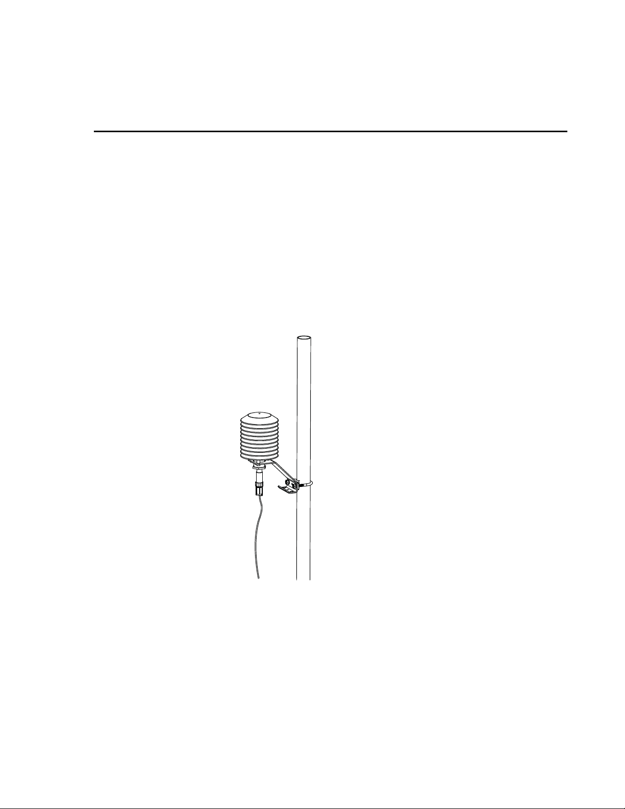
FIGURE 1-1. 083E mounted in a 41003-5 radiation shield
2. Cautionary Statements
• The 083E is a sensitive instrument. It is particularly susceptible to damage
and miss-calibration. Repair and re-calibration should only be attempted
by trained repair technicians. If repair or calibration is required, refer to
the customer assistance statement at the head of this manual and contact
Campbell Scientific.
• Do not touch the sensor element.
1
Page 8
Model 083E Relative Humidity and Temperature Sensor
3. Initial Inspection
• Upon receipt of the 083E, inspect the packaging and contents for damage.
File damage claims with the shipping company.
• The model number and cable length are printed on a label at the
connection end of the cable. Check this information against the shipping
documents to ensure the expected product and cable length are received.
4. Quickstart
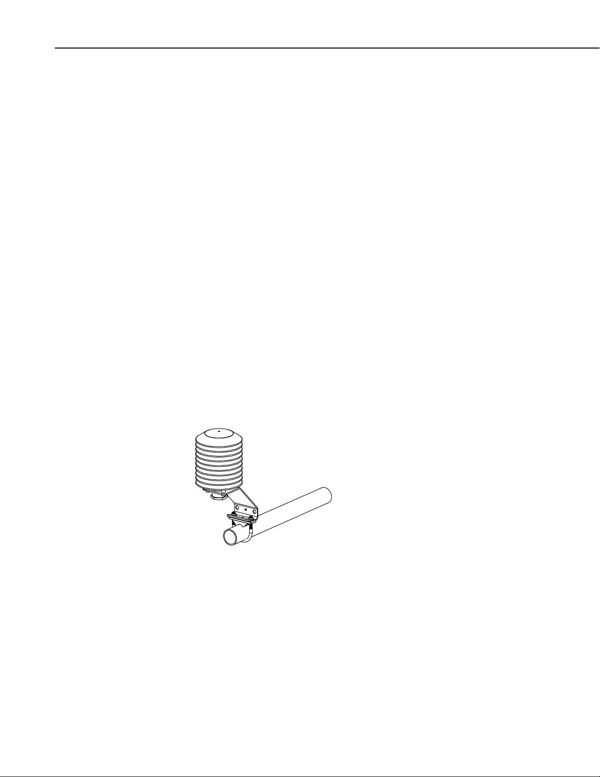
Figure 1-1 shows the 083E installed in a 41003-5 radiation shield. Figures 4-1
and 4-2 show the radiation shield mounted on a crossarm and a mast,
respectively.
4.1 Quick Installation
Review Section 7, Installation for complete instructions. To install the 083E,
you will need:
• 41003-5 Radiation Shield
• 28415 Hex Plug (ships with 083E sensor)
1. Insert the 28415 hex plug that ships with the 083E sensor into the
underside of the 41003-5 base.
2. Attach the radiation shield to the tripod mast, crossarm, or tower leg using
the supplied U-bolt. See Figures 4-1 and 4-2 for examples of shield
mounting.
FIGURE 4-1. 41003-5 radiation shield mounted on a crossarm
2
Page 9
Model 083E Relative Humidity and Temperature Sensor
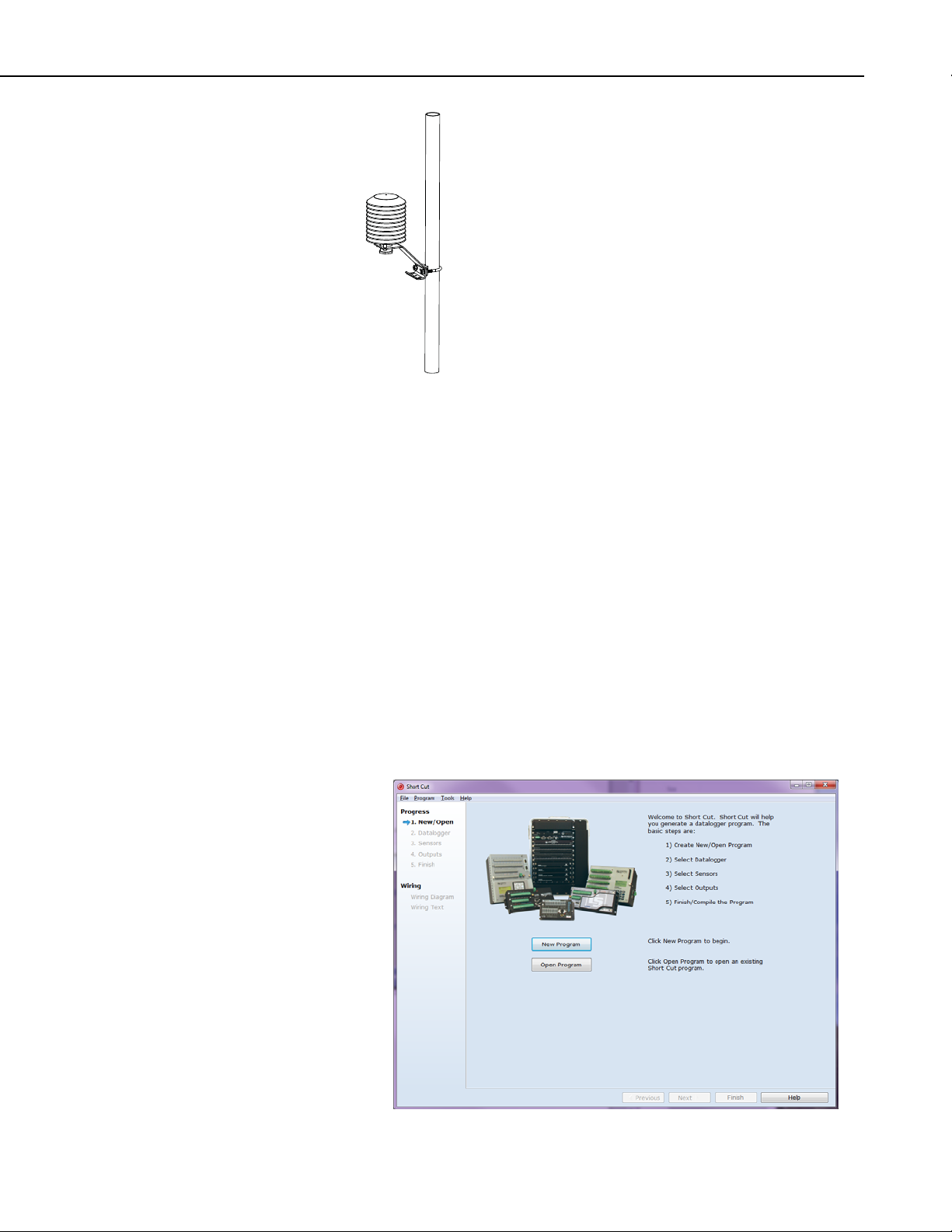
FIGURE 4-2. 41003-5 radiation shield mounted on a mast
3. Insert the sensor through the center of the hex plug at the bottom of the
radiation shield.
4. Tighten the hex plug such that it compresses against the body of the 083E
to hold it inside the radiation shield.
5. Attach the sensor cable to the connector on the bottom of the 083E.
6. Secure sensor cable to mast or crossarm with cable ties.
4.2 Programming with Short Cut
Short Cut Program Generator for Windows can be used to program the
CR1000 datalogger to measure the 083E as outlined in the following
procedure. Short Cut can also be used to program other 083E compatible
Campbell Scientific dataloggers.
1. Open Short Cut and click on New Program.
3
Page 10

Model 083E Relative Humidity and Temperature Sensor
2. Select a scan interval.
3. Select 083E Temperature and Relative Humidity Sensor and click the
right arrow to add it to the list of sensors to be measured.
4
Page 11

Model 083E Relative Humidity and Temperature Sensor
4. Define the name of the public variables. Variables default to AirTC and
RH that hold the air temperature and relative humidity measurements.
Select the desired units of measure. Units default to Deg C.
5. Sensor connections to the CR1000 datalogger are shown in the Wiring
tab.
5
Page 12

Model 083E Relative Humidity and Temperature Sensor
6. Select the desired output data for final storage and click Finish.
5. Overview
7. A full description of sensor wiring can be found by selecting Wiring
Diagram at the left of the Short Cut window. Send the program from the
PC to the CR1000 datalogger if telecommunications link is active.
6
The 083E is a microprocessor-controlled relative humidity and temperature
sensor. Relative humidity response is linear with negligible hysteresis or
temperature dependence. The temperature sensor is a three-element composite
thermistor type with linear response over the range of –50°C to 50°C. The
sensor is designed to be mounted in a radiation shield when used outdoors.
Page 13

6. Specifications
Features:
Compatibility
Dataloggers: CR800 series
CR1000
CR3000
Measurement
Ranges
RH: 0 to 100% relative humidity
Temperature: -50° to 50°C (-58° to 122°F)
Accuracies
RH: ±2.0% from 0 to 100% RH
Temperature: ±0.10° C (0.18° F)
Response
RH: 10 s with 2 m/s wind aspiration
Temperature
Operating: -50° to 50°C (-58° to 122°F)
See Section 8.2, Limitations of RH Measurement at
Compensation: RH is temperature compensated internally
Model 083E Relative Humidity and Temperature Sensor
• Relative humidity sensing element: thin film polymer capacitor
• Temperature sensing element: thermistor
Below Freezing Temperatures.
7. Installation
7.1 Siting
Power requirement
Source: 10 to 18 Vdc
Load: < 5 mA
Outputs
RH: 0 to 1 Vdc
Temperature: Resistive bridge
Dimensions
Length: 216 mm (8.5 in)
Diameter: 19 mm (0.75 in)
If the sensor is to be mounted in a radiation shield, refer to the radiation shield
manual section for mounting details. A typical installation is illustrated in the
Section 7.2, Mounting.
Sensors not installed in a radiation shield should be mounted in a representative
location having good airflow and shaded from sunlight or other radiant heat
source.
Locate sensors over an open level area at least 9 m (EPA) in diameter. The
surface should be covered by short grass, or where grass does not grow, the
natural earth surface. Locate sensors away from objects at least a distance
equal to four times the height of the objects, and at least 30 m (EPA) from
7
Page 14

Model 083E Relative Humidity and Temperature Sensor
large paved areas. Protect sensors from thermal radiation and ensure adequate
ventilation.
Standard measurement heights:
1.5 m (AASC)
1.25 to 2.0 m (WMO)
2.0 m (EPA)
See Section 10, References for a list of sources that discuss temperature and
relative humidity sensors and siting.
7.2 Mounting
8
FIGURE 7-1. 092 mounted in 41003-5 radiation shield
Page 15

7.3 Wiring Instructions
Model 083E Relative Humidity and Temperature Sensor
Datalogger
083E Pin
Number
(pin F not used)
A White Power 12V
B Green Ground Signal Ground G G
C Blue Signal ref
D Black
E Red Signal temp
Clear Shield Shield
Wire
Color Cable Label Description
+10 to +18
Vdc
RH Analog
Output
Signal reference
temperature
Temperature
Common
Temperature
Signal
Datalogger
Channel
CR800
CR850
CR5000
CR3000
CR1000
CR23X
12V 12V
SE SE
SE SE
EX or VX EX or VX
Channel
CR10(X)
CR500
CR510
AG
G
Jumped
Resistor
28430
Jump resistor
between SE and
VX
7.4 Programming
This section is for users who write their own CRBasic datalogger programs.
To use the Short Cut program builder, see Section 4, Quickstart.
7.4.1 Programming Example
Table 7-1 describes the sensor wiring used with the following example
CRBasic datalogger program.
TABLE 7-1. 083E Sensor Wiring for Example Program
Wire
Color
White Power 12V 12V
Green Ground G
Blue Signal ref SE1
Black
Red Signal temp SE8
Clear Shield
Cable Label
Signal reference
temperature
Datalogger
Channel
CR1000
VX1
Jumped
Resistor
28430
Jump resistor
between SE8
and VX1
9
Page 16

Model 083E Relative Humidity and Temperature Sensor
'CR1000 program to measure 083E-L
Public MetOne_083E_Temp
Public MetOne_083E_RH
DataTable(Table1,True,-1)
DataInterval(0,10,Min,10)
Average(1,MetOne_083E_Temp,FP2,False)
Sample(1,MetOne_083E_RH,FP2)
EndTable
'Main Program
BeginProg
Scan (5,Sec,1,0)
'MetOne 083E Temperature in Degrees C
BrHalf (MetOne_083E_Temp,1,mV2500,8,Vx1,1,2000,True ,0,_60Hz,-178.89,105.99)
'MetOne 083E Relative Humidity
VoltSe (MetOne_083E_RH,1,mv2500C,2,1,0,_60Hz,0.1,0)
CallTable(Table1)
NextScan
EndProg
8. Operation
8.1 Sensor Verification
To verify correct wiring and test the basic sensor operation, blow on the sensor.
The moisture in your breath should cause the relative humidity reading to rise.
To ensure proper operation, check the output data against a relative humidity
and temperature measuring device such as a psychrometer. Local weather
service data should be used only as a guideline since relative humidity and
temperature can vary significantly over short distances and over brief periods
of time.
10
Page 17

Model 083E Relative Humidity and Temperature Sensor
8.2 Limitations of RH Measurements at Below Freezing Temperatures
The relative humidity measurement is referenced to saturated water vapor
pressure above liquid water. When air temperature is below freezing, the
maximum theoretical measurement range is limited as follows:
Air Temperature
(Deg C)
0 100
-5 96
-10 92
-15 88
-20 84
-25 80
-30 76
-35 72
-40 68
-45 64
-50 60
Maximum RH
(%)
11
Page 18

Model 083E Relative Humidity and Temperature Sensor
8.3 Temperature Table
The temperature sensor is a resistive device. A resistance measurement across
the red and black leads of the 083E should equal the resistances listed in Table
8-1 at the stated temperatures.
TABLE 8-1. Model 083E-1-X Temperature vs. Sensor Resistance
YSI thermistor bead 44212
Temp ( ° C) RCAL (Ω Ohms) Temp ( ° C) RCAL (Ω Ohms) Temp ( ° C) RCAL (Ω Ohms)
-50 158181 -16 49648 18 22404
-49 150561 -15 48389 19 21908
-48 143555 -14 47173 20 21423
-47 137093 -13 45997 21 20949
-46 131114 -12 44861 22 20484
-45 125564 -11 43761 23 20029
-44 120400 -10 42696 24 19583
-43 115583 -9 41665 25 19147
-42 111079 -8 40665 26 18719
-41 106858 -7 39696 27 18300
-40 102895 -6 38755 28 17889
-39 99166 -5 37843 29 17487
-38 95651 -4 36957 30 17092
-37 92333 -3 36097 31 16705
-36 89196 -2 35260 32 16325
-35 86224 -1 34447 33 15952
-34 83406 0 33657 34 15586
-33 80729 1 32888 35 15227
-32 78183 2 32139 36 14875
-31 75760 3 31410 37 14529
-30 73449 4 30700 38 14190
-29 71245 5 30009 39 13856
-28 69138 6 29335 40 13528
-27 67124 7 28677 41 13206
-26 65195 8 28037 42 12890
-25 63348 9 27411 43 12579
-24 61576 10 26801 44 12274
-23 59875 11 26206 45 11974
-22 58242 12 25624 46 11678
-21 56671 13 25056 47 11388
-20 55160 14 24501 48 11102
-19 53705 15 23959 49 10822
-18 52303 16 23429 50 10545
-17 50952 17 22911
12
Following are polynomial expressions derived from Table 8-1.
T
= ((((R
c
= ((((-129.163 Tc) + 13698.3) ⎯1) – 23100 ⎯1)
R
t
⎯1
) + (23100 ⎯1)) ⎯1) – 13698.3) ⁄ -129.163
t
⎯1
Where: Tc = temperature in °C and Rt = sensor resistance in ohms (Ω)
Page 19

Model 083E Relative Humidity and Temperature Sensor
9. Maintenance and Troubleshooting
9.1 Maintenance Schedule
The 083E is designed to operate for an extended period with minimum
maintenance. However, it can be damaged by untrained personnel attempting
disassembly or calibration.
6 – 12 Month Intervals:
• Inspect the sensor for proper operation per Section 8.1, Sensor
Verification.
12 Month Interval:
• Return the sensor to Campbell Scientific for calibration and
replacement of the O-rings and the filter membrane.
10. References
AASC, 1985: The State Climatologist (1985) Publication of the American
Association of State Climatologists: Heights and Exposure Standards for
Sensors on Automated Weather Stations, v. 9, No. 4 October, 1985.
(http://www.stateclimate.org/publications/state-climatologist/NOAA-
NCY-SCBOOKS-SC77097/00000029.pdf)
EPA, 2000: Meteorological Monitoring Guidance for Regulatory Modeling
Applications, EPA-454/R-99-005. Office of Air Quality Planning and
Standards, Research Triangle Park, North Carolina 27711
EPA, 2008: Quality Assurance Handbook for Air Pollution Measurement
Systems, Vol. IV, Meteorological Measurements, Ver. 2.0, EPA-454/B08-002 (revised 2008). Office of Air Quality Planning and Standards,
Research Triangle Park, NC 27711
Goff, J. A. and S. Gratch, 1946: Low-pressure properties of water from -160°
to 212°F, Trans. Amer. Soc. Heat. Vent. Eng., 51, 125-164.
Lowe, P. R., 1977: An approximating polynomial for the computation of
saturation vapor pressure, J. Appl. Meteor., 16, 100-103.
Meyer, S. J. and K. G. Hubbard, 1992: Nonfederal Automated Weather
Stations and Networks in the United States and Canada: A Preliminary
Survey, Bulletin Am. Meteor. Soc. 73, No. 4, 449-457.
Weiss, A., 1977: Algorithms for the calculation of moist air properties on a
hand calculator, Amer. Soc. Ag. Eng., 20, 1133-1136.
WMO, 2008. Guide to Meteorological Instruments and Methods of
Observation. World Meteorological Organization No. 8, 7
Geneva, Switzerland.
th
edition,
13
Page 20

Model 083E Relative Humidity and Temperature Sensor
14
Page 21

Page 22

Campbell Scientific Companies
Campbell Scientific, Inc. (CSI)
815 West 1800 North
Logan, Utah 84321
UNITED STATES
www.campbellsci.com
Campbell Scientific Africa Pty. Ltd. (CSAf)
Somerset West 7129
SOUTH AFRICA
www.csafrica.co.za
Campbell Scientific Australia Pty. Ltd. (CSA)
Garbutt Post Shop QLD 4814
www.campbellsci.com.au
Campbell Scientific do Brazil Ltda. (CSB)
Rua Luisa Crapsi Orsi, 15 Butantã
CEP: 005543-000 São Paulo SP BRAZIL
www.campbellsci.com.br
Campbell Scientific Canada Corp. (CSC)
11564 - 149th Street NW
Edmonton, Alberta T5M 1W7
www.campbellsci.ca
Campbell Scientific Centro Caribe S.A. (CSCC)
300 N Cementerio, Edificio Breller
Santo Domingo, Heredia 40305
www.campbellsci.cc
Campbell Scientific Ltd. (CSL)
Shepshed, Loughborough LE12 9GX
UNITED KINGDOM
www.campbellsci.co.uk
Campbell Scientific Ltd. (France)
3 Avenue de la Division Leclerc
www.campbellsci.fr
Campbell Scientific Spain, S. L.
Avda. Pompeu Fabra 7-9, local 1
www.campbellsci.es
Please visit www.campbellsci.com to obtain contact information for your local US or International representative.
• info@campbellsci.com
PO Box 2450
• cleroux@csafrica.co.za
PO Box 8108
AUSTRALIA
• info@campbellsci.com.au
• suporte@campbellsci.com.br
CANADA
• dataloggers@campbellsci.ca
COSTA RICA
• info@campbellsci.cc
Campbell Park
80 Hathern Road
• sales@campbellsci.co.uk
92160 ANTONY
FRANCE
• info@campbellsci.fr
08024 Barcelona
SPAIN
• info@campbellsci.es
 Loading...