

Page 1

Model 024A Met One
Wind Direction Sensor
Revision: 10/12
Copyright © 1989-2012
Campbell Scientific, Inc.
Page 2

Page 3

Warranty
“PRODUCTS MANUFACTURED BY CAMPBELL SCIENTIFIC, INC. are
warranted by Campbell Scientific, Inc. (“Campbell”) to be free from defects in
materials and workmanship under normal use and service for twelve (12)
months from date of shipment unless otherwise specified in the corresponding
Campbell pricelist or product manual. Products not manufactured, but that are
re-sold by Campbell, are warranted only to the limits extended by the original
manufacturer. Batteries, fine-wire thermocouples, desiccant, and other
consumables have no warranty. Campbell's obligation under this warranty is
limited to repairing or replacing (at Campbell's option) defective products,
which shall be the sole and exclusive remedy under this warranty. The
customer shall assume all costs of removing, reinstalling, and shipping
defective products to Campbell. Campbell will return such products by surface
carrier prepaid within the continental United States of America. To all other
locations, Campbell will return such products best way CIP (Port of Entry)
INCOTERM® 2010, prepaid. This warranty shall not apply to any products
which have been subjected to modification, misuse, neglect, improper service,
accidents of nature, or shipping damage. This warranty is in lieu of all other
warranties, expressed or implied. The warranty for installation services
performed by Campbell such as programming to customer specifications,
electrical connections to products manufactured by Campbell, and product
specific training, is part of Campbell’s product warranty. CAMPBELL
EXPRESSLY DISCLAIMS AND EXCLUDES ANY IMPLIED
WARRANTIES OF MERCHANTABILITY OR FITNESS FOR A
PARTICULAR PURPOSE. Campbell is not liable for any special, indirect,
incidental, and/or consequential damages.”
Page 4

Assistance
Products may not be returned without prior authorization. The following
contact information is for US and international customers residing in countries
served by Campbell Scientific, Inc. directly. Affiliate companies handle
repairs for customers within their territories. Please visit
www.campbellsci.com to determine which Campbell Scientific company serves
your country.
To obtain a Returned Materials Authorization (RMA), contact CAMPBELL
SCIENTIFIC, INC., phone (435) 227-9000. After an applications engineer
determines the nature of the problem, an RMA number will be issued. Please
write this number clearly on the outside of the shipping container. Campbell
Scientific's shipping address is:
CAMPBELL SCIENTIFIC, INC.
RMA#_____
815 West 1800 North
Logan, Utah 84321-1784
For all returns, the customer must fill out a "Statement of Product Cleanliness
and Decontamination" form and comply with the requirements specified in it.
The form is available from our web site at www.campbellsci.com/repair. A
completed form must be either emailed to repair@campbellsci.com or faxed to
(435) 227-9106. Campbell Scientific is unable to process any returns until we
receive this form. If the form is not received within three days of product
receipt or is incomplete, the product will be returned to the customer at the
customer's expense. Campbell Scientific reserves the right to refuse service on
products that were exposed to contaminants that may cause health or safety
concerns for our employees.
Page 5

Table of Contents
PDF viewers: These page numbers refer to the printed version of this document. Use the
PDF reader bookmarks tab for links to specific sections.
1. Introduction.................................................................1
2. Cautionary Statements...............................................1
3. Initial Inspection .........................................................1
4. Quickstart .................................................................... 2
4.1 Step 1 — Mount the Sensor .................................................................2
4.2 Step 2 — Use SCWin Short Cut to Program Datalogger and
Generate Wiring Diagram.................................................................4
5. Overview......................................................................6
6. Specifications .............................................................7
7. Installation...................................................................7
7.1 Siting ....................................................................................................7
7.2 Mounting Options ................................................................................8
7.3 Wiring ..................................................................................................9
7.4 Programming........................................................................................9
7.4.1 Datalogger Instruction...................................................................9
7.4.2 Calibration and Orientation.........................................................10
7.4.3 Example Programs......................................................................11
8. Maintenance ..............................................................13
8.1 6 to 12 Month Periodic Service *.......................................................13
8.2 24 to 36 Month Service *...................................................................13
9. References ................................................................17
Appendix
Wind Direction Sensor Orientation ....................... A-1
A.
A.1 Determining True North and Sensor Orientation ............................ A-1
i
Page 6

Table of Contents
Figures
Tables
4-1. Bushing installation on 024A sensor ................................................... 2
4-2. The 024A mounted to a crossarm via the 17953 NU-RAIL................ 3
7-1. CM220 mount attached to a crossarm................................................. 8
7-2. CM216 mount...................................................................................... 8
7-3. Schematic of 024A Wind Direction Sensor......................................... 9
8-1. Cable diagram.................................................................................... 14
8-2. Parts diagram..................................................................................... 15
A-1. Magnetic declination for the contiguous United States (2004)........ A-2
A-2. Declination angles east of True North are subtracted from 0 to
get True North.............................................................................. A-3
A-3. Declination angles west of True North are added to 0 to get
True North ................................................................................... A-3
5-1. Recommended Cable Lengths............................................................. 6
7-1. Connections to Campbell Scientific Dataloggers ................................ 9
7-2. Parameters for Wind Direction.......................................................... 10
8-1. Met-One Parts List Reproduced by Campbell Scientific, Inc............ 16
ii
Page 7

024A Met-One Wind Direction Sensor
1. Introduction
The 024A is a wind vane manufactured by Met One. It measures wind
direction only and is traditionally used in tandem with Met One’s 014A Wind
Speed Sensor.
Before installing the 024A, please study
• Section 2, Cautionary Statements
• Section 3, Initial Inspection
• Section 4, Quickstart
2. Cautionary Statements
• The 024A is a precision instrument. Please handle it with care.
• If the 024A is to be installed at heights over 6 feet, be familiar with tower
safety and follow safe tower climbing procedures.
• Danger—Use extreme care when working near overhead electrical wires.
Check for overhead wires before mounting the 024A or before raising a
tower.
• The black outer jacket of the cable is Santoprene® rubber. This
compound was chosen for its resistance to temperature extremes, moisture,
and UV degradation. However, this jacket will support combustion in air.
It is rated as slow burning when tested according to U.L. 94 H.B. and will
pass FMVSS302. Local fire codes may preclude its use inside buildings.
3. Initial Inspection
• Upon receipt of the 024A, inspect the packaging and contents for damage.
File damage claims with the shipping company. Immediately check
package contents against the shipping documentation. Contact Campbell
Scientific about any discrepancies.
• The model number and cable length are printed on a label at the
connection end of the cable. Check this information against the shipping
documents to ensure the expected product and cable length are received.
1
Page 8
024A Met-One Wind Direction Sensor
4. Quickstart
4.1 Step 1 — Mount the Sensor
Please review Section 7, Installation, for siting and other guidelines.
Install the 024A using:
• CM220 Right-Angle Mounting Kit, or
• 17953 1 x 1 inch NURAIL Crossover Fitting
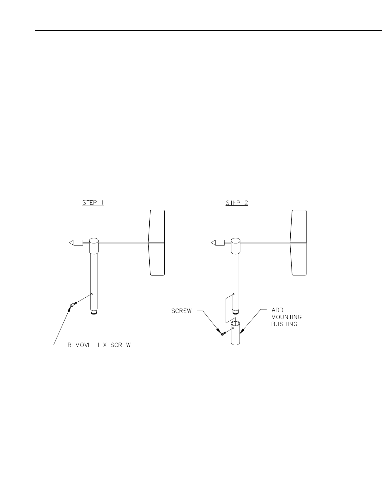
1. Remove the Allen hex screw in the lower part of the sensor housing (see
FIGURE 4-1).
2. Insert the 024A in the mounting bushing (see FIGURE 4-1).
3. Tighten the screw in the bushing onto the sensor housing (see FIGURE
4-1).
2
FIGURE 4-1. Bushing installation on 024A sensor
4. Mount a CM202, CM204, or CM206 crossarm to a tripod or tower.
5. Orient the crossarm north-south, with the CM220 or 17953 NU-RAIL on
the north end. Appendix A contains detailed information on determining
True North using a compass and the magnetic declination for the site.
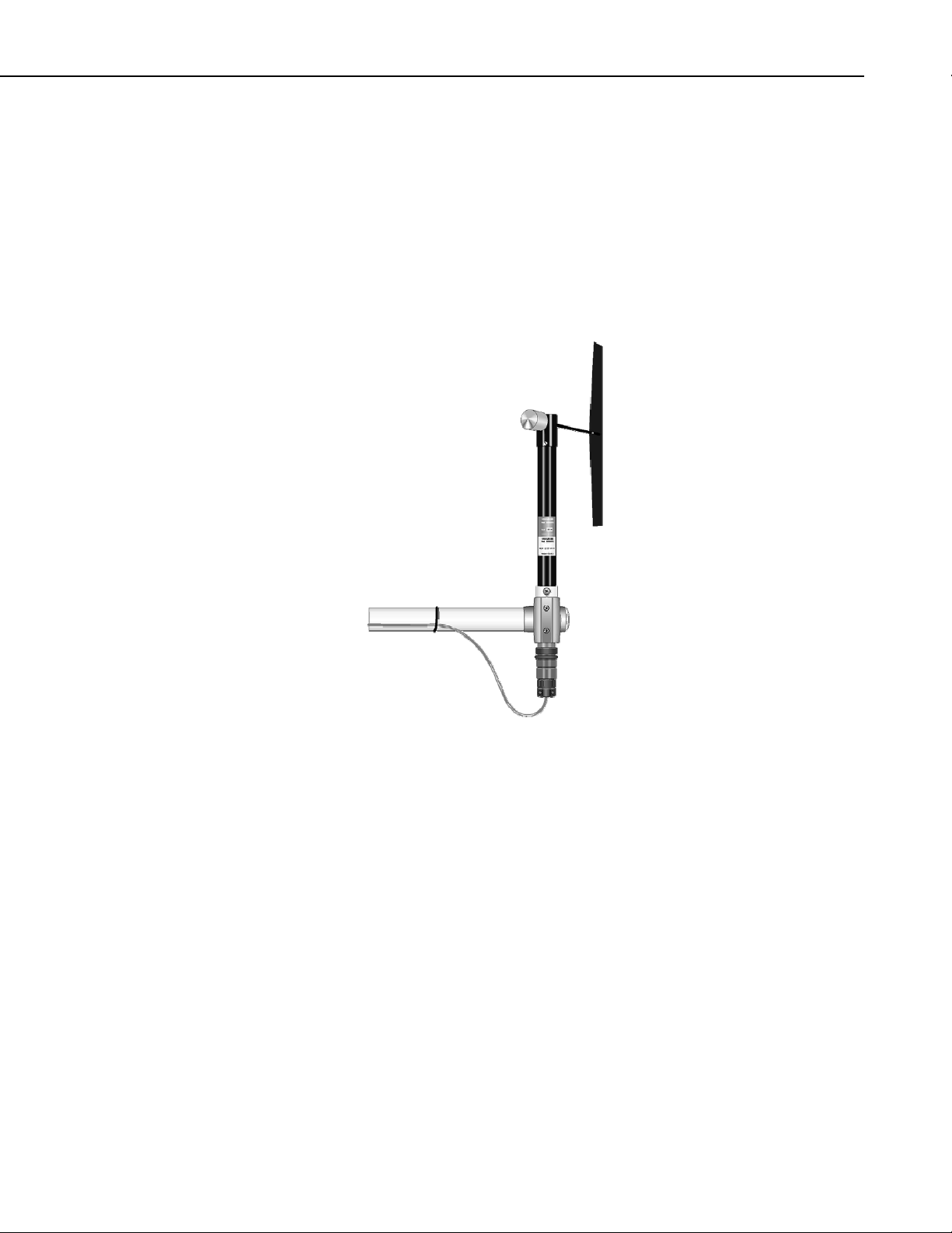
6. Insert the sensor in the CM220 or NU-RAIL fitting (see FIGURE 4-2).
Page 9
024A Met-One Wind Direction Sensor
7. Align the sensor so that the counter weight points to True South and
tighten the U-bolts on the CM220 or tighten the set screws on the NURAIL fitting.
8. Connect the cable assembly to the sensor receptacle.
9. Route the sensor cable along the underside of the crossarm to the tripod or
tower, and to the instrument enclosure.
10. Secure the cable to the crossarm and tripod or tower using cable ties.
FIGURE 4-2. The 024A mounted to a crossarm via the 17953 NU-RAIL
3
Page 10

024A Met-One Wind Direction Sensor
4.2 Step 2 — Use SCWin Short Cut to Program Datalogger and Generate Wiring Diagram
The simplest method for programming the datalogger to measure the 024A is
to use Campbell Scientific's SCWin Short Cut Program Generator.
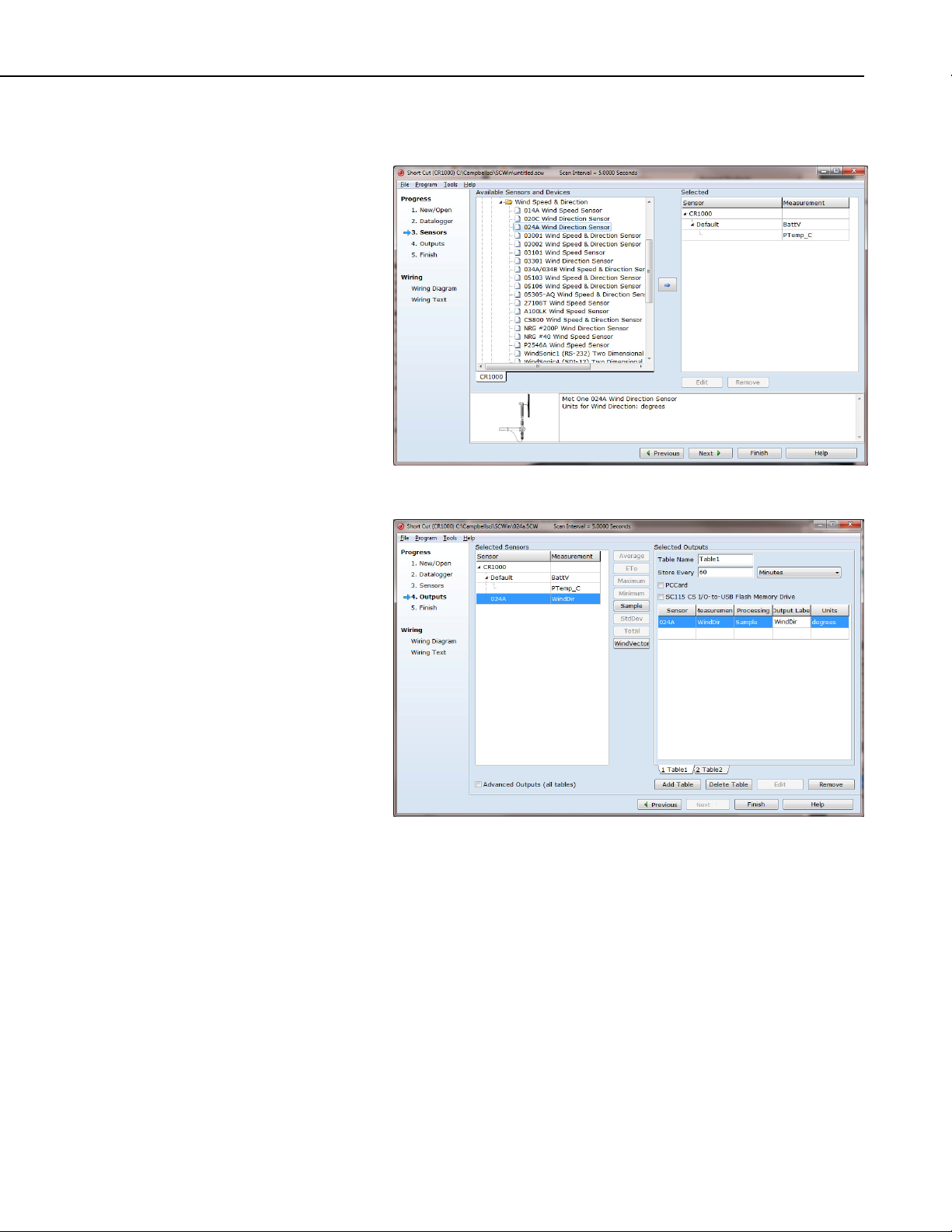
1. Open Short Cut and click on New Program.
2. Select the datalogger and enter the scan interval.
4
Page 11
024A Met-One Wind Direction Sensor
3. Select 024A Wind Direction Sensor and select the right arrow to add it to
the list of sensors to be measured then select next.
4. Select Sample for the output and then select finish
5
Page 12

024A Met-One Wind Direction Sensor
5. Wire according to the wiring diagram generated by SCWin Short Cut.
5. Overview
Met One's 024A is a wind vane that measures wind direction from 0 to 360
degrees with a 5 degree accuracy. It uses a 10-kohm potentiometer to sense
wind direction. A datalogger applies a precision excitation voltage to the
potentiometer, resulting in an analog voltage output that is directly proportional
to the wind direction's azimuth.
Cable length for the 024A is specified when the sensor is ordered. TABLE 5-1
gives the recommended cable length for mounting the sensor at the top of a
tripod/tower via a CM202 crossarm.
TABLE 5-1. Recommended Cable Lengths
CM106 CM110 CM115 CM120 UT10 UT20 UT30
11 ft 14 ft 19 ft 24 ft 14 ft 24 ft 37 ft
The 024A's cable can terminate in:
• Pigtails that connect directly to a Campbell Scientific datalogger
(option –PT).
• Connector that attaches to a prewired enclosure (option –PW). Refer
to www.campbellsci.com/prewired-enclosures for more information.
6
Page 13

6. Specifications
Compatible Dataloggers: CR200(X)
CR800 series
CR1000
CR3000
CR5000
CR9000(X)
CR510
CR10(X)
CR23X
CR7
21X
Range: 0 to 360 degrees
Threshold: 0.447 m s
Accuracy: ±5 degrees
Temperature Range: -50° to +70°C
024A Met-One Wind Direction Sensor
-1
(1.0 mph)
7. Installation
7.1 Siting
Delay Distance: Less than 1.5 m (5 ft.)
Damping Ratio
Standard: 0.25
Optional: 0.4
Potentiometer Specifications
Sand, Dust, and Fungus: MIL-E-5272
Salt Spray: MIL-E-12934
Resistance: 0 to 10,000 ohms
Weight: 450 g (1 lb)
Dimensions
Overall Height: 33.8 cm (13.3 in)
Overall Length: 44.7 cm (17.6 in)
Tail Height: 30.5 cm (12 in)
Tail Width: 7.6 cm (3 in)
Locate wind sensors away from obstructions (e.g. trees and building). As a
general rule of thumb there should be a horizontal distance of at least ten times
the height of the obstruction between the windset and the obstruction. If it is
necessary to mount the sensors on the roof of a building, the height of the
sensors, above the roof, should be at least 1.5 times the height of the building.
See Section 9, References, for a list of references that discuss siting wind
direction sensors.
7
Page 14

024A Met-One Wind Direction Sensor
7.2 Mounting Options
The 024A can be attached to a CM202, CM204, or CM206 crossarm via a
17953 NU-RAIL fitting (see FIGURE 4-2 in Quickstart) or a CM220 Right
Angle Mounting Bracket (see FIGURE 7-1). Alternatively, the 024A can be
attached to the top of our stainless-steel tripods via the CM216 Sensor
Mounting Kit (see FIGURE 7-2). The CM216 extends 4 in. above the mast of
a stainless-steel CM110, CM115, or CM120 tripod.
FIGURE 7-1. CM220 mount attached to a crossarm
8
FIGURE 7-2. CM216 mount
Page 15

7.3 Wiring
024A Met-One Wind Direction Sensor
FIGURE 7-3. Schematic of 024A Wind Direction Sensor
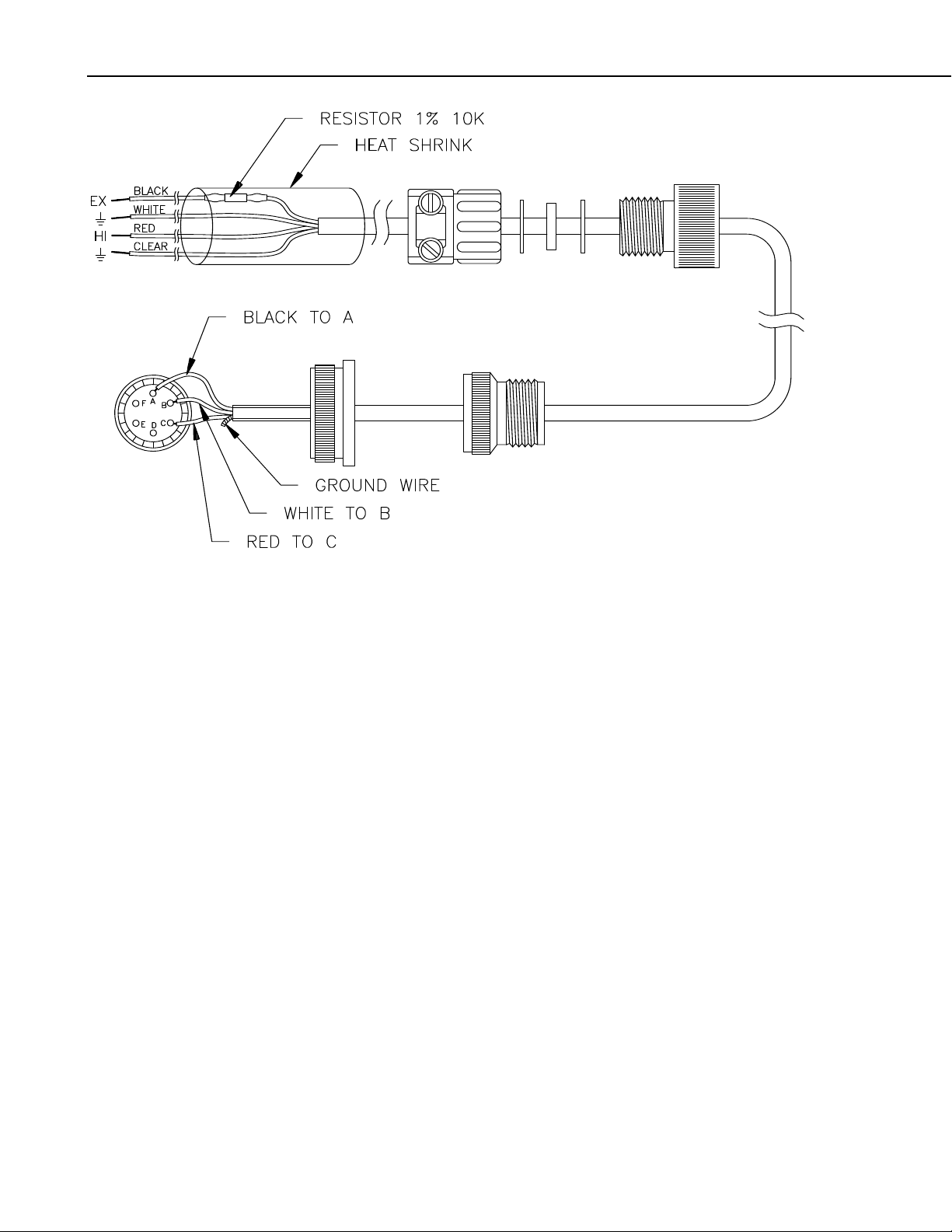
FIGURE 7-3 and TABLE 7-1 shows wiring; a detailed cable diagram is
provided in Section 8, Maintenance (FIGURE 8-1). When Short Cut is used to
create the datalogger program, the sensor should be wired to the channels
shown on the wiring diagram created by Short Cut.
TABLE 7-1. Connections to Campbell Scientific Dataloggers
Color
Description
Red Wind Dir. Signal SE Analog SE Analog SE Analog SE Analog
Black Wind Dir. Excitation Excitation Excitation Excitation Excitation
White Wind Dir. Reference
Clear Wind Dir. Shield
7.4 Programming
NOTE
7.4.1 Datalogger Instruction
This section is for users who write their own programs. A
datalogger program to measure this sensor can be created using
Campbell Scientifics’ Short Cut Program Builder software. You
do not need to read this section to use Short Cut.
The datalogger instruction that measures the 024A is datalogger dependent.
The BRHalf() measurement instruction is used for our CR800, CR850,
CR1000, CR3000, and CR5000 dataloggers. Our CR200(X)-series dataloggers
use the EX-DEL_SE(). Our Edlog dataloggers (e.g., CR510, CR10(X),
CR23X) use Instruction 4 – Excite, Delay, Measure. Excitation voltages, range
CR800
CR5000
CR3000
CR1000
CR510
CR500
CR10(X)
AG
G
21X
CR7
CR23X
CR200(X)
9
Page 16

024A Met-One Wind Direction Sensor
codes, and delays for CSI dataloggers are listed in TABLE 7-2. The process
for determining the correct multiplier is provided in Section 7.4.2, Calibration
and Orientation.
TABLE 7-2. Parameters for Wind Direction
Measurement
Range
Excitation
CR200(X)
2500 mV 250 mV, fast 500 mV, fast 2500 mV,
CR10(X),
CR510
CR7, 21X,
CR23X
CR800, CR850,
CR1000
250 microsecond
integration,
reverse excitation
CR5000,
CR3000
5000 mV,
250 microsecond
integration, reverse
excitation
2500 mV 500 mV 1000 mV 2500 mV 5000 mV
Voltage
Delay or Settling
2 ms 2 ms 2 ms 2 ms 2 ms
Time
Multiplier See Section
7.4.2
See Section
7.4.2
See Section
7.4.2
See Section 7.4.2 See Section 7.4.2
Offset 0 0 0 0 0
7.4.2 Calibration and Orientation
Conversion of the voltage output into wind direction is done by entering the
proper multiplier. The proper multiplier is calculated by dividing 360 by the
full scale input voltage (i.e., 360/FSIV). The full scale input voltage (FSIV) is
the maximum voltage output from the wind vane. This is found by creating a
datalogger program with a multiplier of 1, the default excitation, and a fast
scan interval. With a multiplier of 1, the value stored in the variable or input
location is simply the voltage output. Slowly turn the wind vane; the shoulder
screw must first be removed. The maximum value observed is the full scale
input voltage (FSIV).
10
NOTE
If the reading is -99999, exceeds 500 on the 21X or CR7, or
exceeds 250 on the CR10, then reduce the millivolts of excitation
by 5 mV.
Multiplier 360/FSIV*
Offset 0.0
*FSIV = Full scale input voltage
Enter the calculated multiplier in the program.
Orientation of the 024A Wind Direction Sensor should be complete if the 024A
counter weight was aligned due south.
Page 17

7.4.3 Example Programs
024A Met-One Wind Direction Sensor
NOTE
For these examples, the multiplier is listed as 1. The multiplier is
unique to individual devices. Follow the procedure provided in
Section 7.4.2, Calibration and Orientation, to acquire the correct
multiplier for your sensor.
'CR200(X) Series
'Created by Short Cut (2.5)
'Declare Variables and Units
Public Batt_Volt
Public WindDir
Public NewMult
Units Batt_Volt=Volts
Units WindDir=degrees
'Define Data Tables
DataTable(Table2,True,-1)
DataInterval(0,1440,Min)
Minimum(1,Batt_Volt,False,False)
EndTable
'Main Program
BeginProg
Scan(10,Sec)
'Default Datalogger Battery Voltage measurement Batt_Volt:
Battery(Batt_Volt)
'024A Wind Direction Sensor measurement WindDir:
ExDelSE(WindDir,1,1,1,2500,2000,1.0,0)
NewMult=360/WindDir
'Call Data Tables and Store Data
CallTable(Table2)
NextScan
EndProg
'CR1000
'Created by Short Cut (2.5 Beta)
'Declare Variables and Units
Public Batt_Volt
Public WindDir
Public NewMult
Units Batt_Volt=Volts
Units WindDir=degrees
'Define Data Tables
DataTable(Table1,True,-1)
DataInterval(0,60,Min,10)
Sample(1,WindDir,FP2)
EndTable
DataTable(Table2,True,-1)
DataInterval(0,1440,Min,10)
Minimum(1,Batt_Volt,FP2,False,False)
EndTable
11
Page 18

024A Met-One Wind Direction Sensor
'Main Program
BeginProg
Scan(5,Sec,1,0)
'Default Datalogger Battery Voltage measurement Batt_Volt:
Battery(Batt_Volt)
'024A Wind Direction Sensor measurement WindDir:
BrHalf(WindDir,1,mV2500,1,1,1,2500,True,2000,250,1.0,0)
NewMult=360/WindDir
'Call Data Tables and Store Data
CallTable(Table1)
CallTable(Table2)
NextScan
EndProg
'CR3000
'Created by Short Cut (2.5)
'Declare Variables and Units
Public Batt_Volt
Public WindDir
Public NewMult
Units Batt_Volt=Volts
Units WindDir=degrees
'Define Data Tables
DataTable(Table1,True,-1)
DataInterval(0,60,Min,10)
Sample(1,WindDir,FP2)
EndTable
DataTable(Table2,True,-1)
DataInterval(0,1440,Min,10)
Minimum(1,Batt_Volt,FP2,False,False)
EndTable
'Main Program
BeginProg
Scan(5,Sec,1,0)
'Default Datalogger Battery Voltage measurement Batt_Volt:
Battery(Batt_Volt)
'024A Wind Direction Sensor measurement WindDir:
BrHalf(WindDir,1,mV5000,1,1,1,5000,True,2000,250,1.0,0)
NewMult=360/WindDir
'Call Data Tables and Store Data
CallTable(Table1)
CallTable(Table2)
NextScan
EndProg
12
Page 19

024A Met-One Wind Direction Sensor
;{CR10X}
;
*Table 1 Program
01: 10 Execution Interval (seconds)
;Measure sensor. Multiplier is unique to individual devices.
1: Excite-Delay (SE) (P4)
1: 1 Reps
2: 14 250 mV Fast Range
3: 1 SE Channel
4: 1 Excite all reps w/Exchan 1
5: 2 Delay (0.01 sec units)
6: 500 mV Excitation
7: 1 Loc [ wind_dir ]
8: 1.0 Multiplier
9: 0.0 Offset
;Store measurements in final storage
2: If time is (P92)
1: 0000 Minutes (Seconds --) into a
2: 60 Interval (same units as above)
3: 10 Set Output Flag High (Flag 0)
3: Set Active Storage Area (P80)
1: 1 Final Storage Area 1
2: 101 Array ID
4: Real Time (P77)
1: 1220 Year,Day,Hour/Minute (midnight = 2400)
5: Sample (P70)
1: 1 Reps
2: 1 Loc [ wind_dir ]
8. Maintenance
8.1 6 to 12 Month Periodic Service *
Inspect sensor for physical damage and verify that the vane assembly rotates
freely. To verify parts and locations, refer to the parts diagram (FIGURE 8-2)
and the parts list (TABLE 8-1).
8.2 24 to 36 Month Service *
A complete factory overhaul of the sensor, including the replacement of the
potentiometer, is recommended. To send the 024A to Campbell Scientific, the
customer must receive an RMA number and fill out a “Statement of Product
Cleanliness”. For more information, refer to the Assistance section that is at
the beginning of this document.
* Schedule is based on average to adverse environments.
13
Page 20
024A Met-One Wind Direction Sensor
FIGURE 8-1. Cable diagram
14
Page 21

024A Met-One Wind Direction Sensor
FIGURE 8-2. Parts diagram
15
Page 22

024A Met-One Wind Direction Sensor
Item Part No. Description. Qty./Assy
1 102105 Vane Assembly 1
2 101685-1 Wind Dir. Support 1
3 101049-2 Label, Wind Dir. 1
4 101789 Label, Caution 1
5 860015 Screw, Shoulder 1
6 601100 Screw, Pan Hd Ph, 2-56x3/16 3
7 601680 Scrw, Set A/H, 8-32x3/8 2
8 101687 Label, Met-One 1
9 102017 Assy, Potentiometer 1
10 980495 Wire, 22Ga, Yel 1
11 980450 Wire, 22Ga, Blu 1
TABLE 8-1. Met-One Parts List Reproduced by
Campbell Scientific, Inc.
12 980475 Wire, 22Ga, Orn 1
13 995425 Loctite 222 A/R
14 500280 Connector, 6 Pin 1
15 995100 Adhesive, Epoxy A/R
16 995060 Adhesive, Silicone 5ml
17 510020 Cap 1
18
19
20
21 101806 Assembly, Cable Ref
22 101699 Assy Instructions Ref
23 101706 014 & 024 Installation Ref
24 101697 Wir. Diagram Ref
25
26 601850 Scrw, Cap A/H SS 10-32x5/8 1
16
Page 23

9. References
024A Met-One Wind Direction Sensor
The following references give detailed information on siting wind speed and
wind direction sensors.
EPA, 1989: Quality Assurance Handbook for Air Pollution Measurements
System, Office of Research and Development, Research Triangle Park, NC,
27711.
EPA, 1987: On-Site Meteorological Program Guidance for Regulatory
Modeling Applications, EPA-450/4-87-013, Office of Air Quality Planning and
Standards, Research Triangle Park, NC 27711.
The State Climatologist, 1985: Publication of the American Association of
State Climatologists: Height and Exposure Standards, for Sensors on
Automated Weather Stations, vol. 9, No. 4.
WMO, 1983: Guide to Meteorological Instruments and Methods of
Observation, World Meteorological Organization, No. 8, 5th edition, Geneva,
Switzerland.
17
Page 24

024A Met-One Wind Direction Sensor
18
Page 25

Appendix A. Wind Direction Sensor Orientation
A.1 Determining True North and Sensor Orientation
Orientation of the wind direction sensor is done after the datalogger has been
programmed, and the location of True North has been determined. True North is
usually found by reading a magnetic compass and applying the correction for
magnetic declination; where magnetic declination is the number of degrees
between True North and Magnetic North. The preferred method to obtain the
magnetic declination for a specific site is to use a computer service offered by
NOAA at www.ngdc.noaa.gov/geomag. Magnetic declination can also be
obtained from a map or local airport. A general map showing magnetic
declination for the contiguous United States is shown in FIGURE A-1.
Declination angles east of True North are considered negative, and are subtracted
from 360 degrees to get True North as shown FIGURE A-2 (0° and 360° are the
same point on the compass). For example, the declination for Logan, Utah is 14°
East. True North is 360° - 14°, or 346° as read on a compass. Declination angles
west of True North are considered positive, and are added to 0 degrees to get True
North as shown in FIGURE A-3.
Orientation is most easily done with two people, one to aim and adjust the
sensor, while the other observes the wind direction displayed by the datalogger.
1. Establish a reference point on the horizon for True North.
2. Sighting down the instrument center line, aim the nose cone, or
counterweight at True North. Display the input location or variable for wind
direction using a hand-held keyboard display, PC, or palm.
3. Loosen the u-bolt on the CM220 or the set screws on the NU-RAIL that
secure the base of the sensor to the crossarm. While holding the vane
position, slowly rotate the sensor base until the datalogger indicates 0
degrees. Tighten the set screws.
A-1
Page 26

Appendix A. Wind Direction Sensor Orientation
FIGURE A-1. Magnetic declination for the contiguous United States
(2004)
A-2
Page 27

Appendix A. Wind Direction Sensor Orientation
FIGURE A-2. Declination angles east of True North are subtracted
from 0 to get True North
FIGURE A-3. Declination angles west of True North are added to 0 to
get True North
A-3
Page 28

Appendix A. Wind Direction Sensor Orientation
A-4
Page 29

Page 30

Campbell Scientific Companies
Campbell Scientific, Inc. (CSI)
815 West 1800 North
Logan, Utah 84321
UNITED STATES
www.campbellsci.com
Campbell Scientific Africa Pty. Ltd. (CSAf)
Somerset West 7129
SOUTH AFRICA
www.csafrica.co.za
Campbell Scientific Australia Pty. Ltd. (CSA)
Garbutt Post Shop QLD 4814
www.campbellsci.com.au
Campbell Scientific do Brazil Ltda. (CSB)
Rua Luisa Crapsi Orsi, 15 Butantã
CEP: 005543-000 São Paulo SP BRAZIL
www.campbellsci.com.br
Campbell Scientific Canada Corp. (CSC)
11564 - 149th Street NW
Edmonton, Alberta T5M 1W7
www.campbellsci.ca
Campbell Scientific Centro Caribe S.A. (CSCC)
300 N Cementerio, Edificio Breller
Santo Domingo, Heredia 40305
www.campbellsci.cc
Campbell Scientific Ltd. (CSL)
80 Hathern Road
Shepshed, Loughborough LE12 9GX
UNITED KINGDOM
www.campbellsci.co.uk
Campbell Scientific Ltd. (France)
3 Avenue de la Division Leclerc
92160 ANTONY
www.campbellsci.fr
Campbell Scientific Spain, S. L.
Avda. Pompeu Fabra 7-9, local 1
08024 Barcelona
www.campbellsci.es
Please visit www.campbellsci.com to obtain contact information for your local US or interna tional representative.
• info@campbellsci.com
PO Box 2450
• cleroux@csafrica.co.za
PO Box 8108
AUSTRALIA
• info@campbellsci.com.au
• suporte@campbellsci.com.br
CANADA
• dataloggers@campbellsci.ca
COSTA RICA
• info@campbellsci.cc
Campbell Park
• sales@campbellsci.co.uk
FRANCE
• info@campbellsci.fr
SPAIN
• info@campbellsci.es
 Loading...