

Campbell Manufacturing ET106 User Manual

INSTRUCTION MANUAL
ET106 Weather Station
Revision: 9/02
Copyright (c) 1993-2002
Campbell Scientific, Inc.

Warranty and Assistance
The ET106 WEATHER STATION is warranted by CAMPBELL
SCIENTIFIC, INC. to be free from defects in materials and workmanship under
normal use and ser vice for twelve (1 2) months from date of shipment unless
specified otherwise. Batteries have no warranty. CAMPBELL SCIENTIFIC,
INC.'s obligation under this warranty is limited to repairing or replacing (at
CAMPBELL SCIENTIFIC, INC.'s option) defective products. The customer
shall assume all costs of removing, reinstalling, and shipping defective products
to CAMPBELL SCIENTIFIC, INC. CAMPBELL SCIENTIFIC, INC. will
return such products by surface carrier prepaid. This warranty shall not apply
to any CAMPBELL SCIENTIFIC, INC. products which have been subjected to
modification, misuse, neglect, accidents of nature, or shipping damage. This
warranty is in lieu of all other warranties, expressed or implied, including
warranties of merchantability or fitness for a particular purpose. CAMPBELL
SCIENTIFIC, INC. is not liable for special, indirect, incidental, or
consequential damages.
Products may not be returned without prior authorization. The following
contact information is for US and International customers residing in countries
served by Campbell Scientific, Inc. directly. Affiliate companies handle repairs
for customers within their territories. Please visit www.ca mpbellsci.co m to
determine which Campbell Scientific company serves your country. To obtain
a Returned Materials Authorization (RMA), contact CAMPBELL
SCIENTIFIC, INC., phone (435) 753-2342. After an applications engineer
determines the nature of the problem, an RMA number will be issued. Please
write this number clearly on the outside of the shipping container.
CAMPBELL SCIENTIFIC's shipping address is:
CAMPBELL SCIENTIFIC, INC.
RMA#_____
815 West 1800 North
Logan, Utah 84321-1784
CAMPBELL SCIENTIFIC, INC. does not accept collect calls.

ET 106 Weather Station
Table of Contents
PDF viewers note: These page numbers refer to the printed version of this document. Use
the Adobe Acrobat® bookmarks tab for links to specific sections.
1. Preparation and Siting.............................................1-1
1.1 Installation Tasks.................................................................................. 1-1
1.2 Tools Required...................................................................................... 1-2
1.3 Siting and Exposure.............................................................................. 1-5
1.4 Determining True North for Wind Vane Orientation............................ 1-7
2. ET Tower Installation...............................................2-1
2.1 Base Installation.................................................................................... 2-1
2.2 Tower Installation................................................................................. 2-3
2.3 Tower Grounding.................................................................................. 2-4
3. ET Instrumentation Installation ..............................3-1
3.1 Enclosure, Datalogger, Power Supply................................................... 3-2
3.2 Sensor Connection................................................................................ 3-5
3.3 Communication and Data Storage Peripherals...................................... 3-6
3.4 Sealing and Desiccating the Enclosure ............................................... 3-12
4. ET106 Sensor Arm Installation...............................4-1
4.1 Components.......................................................................................... 4-1
4.2 Installation ............................................................................................ 4-1
4.3 Sensor Connection................................................................................ 4-1
4.4 034A Wind Sensor Installation............................................................. 4-2
4.5 RH and Temperature Radiation Shield................................................. 4-3
4.6 Pyranometer.......................................................................................... 4-3
4.7 Soil Temperature Sensor (Optional).....................................................4-3
4.8 Sensor Verification and Clock Set ........................................................ 4-3
4.9 Upgrading an ET101 to an ET106 ........................................................ 4-4
4.10 Sensor Schematics .............................................................................. 4-6
5. ET Software Installation..........................................5-1
5.1 Quick Start Review............................................................................... 5-1
6. Maintenance and Troubleshooting.........................6-1
6.1 Maintenance.......................................................................................... 6-1
6.2 Troubleshooting.................................................................................... 6-3
i

This is a blank page.

Section 1. Preparation and Siting
These guidelines apply to several different Campbell Scientific weather stations.
1.1 Installation Tasks
1.1.1 Indoors
• Immediately upon receipt of your shipment…
⇒ Open shipping cartons.
⇒ Check contents against invoice. Contact CSI immediately about any
shortages.
• Several days prior to the planned installation date…
⇒ Collect tools and site information (Section 1)
⇒ Assemble datalogger, communications device, and power supply in
enclosure (Section 3)
⇒ Install datalogger support software on PC (Section 5)
1.1.2 Outdoors
⇒ Establish communications between the datalogger and the PC
(Section 5)
⇒ Program datalogger, test sensors, and retrieve data (Section 5)
⇒ Trial run the tower / tripod installation, assembling as much as
possible (Section 2)
⇒ Repackage equipment for transport to the field site
• Locate suitable site (Section 1)
• Prepare tower or tripod base (Section 2)
• Tripod and UT10 (3 meter tower) tower stations:
⇒ Raise tripod or tower (Section 2)
⇒ Install instrumentation enclosure (Section 3)
⇒ Install sensors (Section 4)
1-1

Section 1. Preparation and Siting
• UT30 (10 meter tower) tower stations:
• ET101 / ET106 ET Stations:
1.2 Tools Required
⇒ Install 3 to 10 meter level sensors (Section 4)
⇒ Raise tower (Section 2)
⇒ Install instrumentation enclosure (Section 3)
⇒ Install 0 to 3 meter level sensors (Section 4)
⇒ Place instrumentation enclosure low on the ET Tower (Section 3)
⇒ Install sensor option (Section 4)
⇒ Slide enclosure to top of tower and secure with correct orientation
(Section 3)
Tools required to install and maintain a weather station are listed below.
1.2.1 Tools for Tower Installation
All Towers
Shovel
Rake
Open end wrenches: 3/8", 7/16", ½", (2) 9/16"
Magnetic compass
6' Step ladder
CM6/CM10
Tape measure (12')
Level (12" to 24")
Small sledge hammer
Teflon tape or pipe dope
Allen hex wrench (5/6 4)
UT10
Tape measure (12' to 20')
Level (24" to 36")
Pick or di gging bar
Claw H ammer
Materials for concrete form:
Hand saw
(4) 12" wood stakes
(1) 2"x 4"x 8' piece of lumber
(8) 8p double-head nails
(8) 16p double-head nails
Concrete trowels
(2) 1 to 1.5" thick x 24" boards to support base above forms (optional)
Concrete (0.4 cubic yards)
1-2

Section 1. Preparation and Siting
ET Tower
Tape measure (12’ to 20’)
Claw hammer
Level (24” to 36”)
Hand saw
Materials for concrete form:
(4) 1" x 2" x 12" stakes
(2) 2" x 4" x 96" lumber
(12) 8p double-head nails
(8) 16p double-head nails
20 ft form wire
½ Yard concrete
Concrete trowel, edger
Electrical Fish tape or 20 feet of small diameter rope
Wheelbarrow
UT30
Tape measure (12' and 20')
Nut driver (3/8")
Level (36" to 48")
Small sledge hammer
Pliers
Tie wire
Climbing harness
Hard hat
Haul rope (50')
Non-stretch line (20')
Wire rope cutters
Materials for B18 Base and UTEYE Anchors:
(4) Wood stakes 12"
Pick or di gging bar
Concrete form materials (2"x 4" lumber, stakes, saw, hammer, nails, etc.)
Concrete trowel and edger
Materials for UTDUK Duckbill Anchors
Sledgehammer
Highlift jack
Chain (to attach jack to anchor loops)
Materials for RFM18 Base:
(3) anchors appropriate for mounting surface
(3) bolts and washers to secure base to anchors
1.2.2 Tools for Instrumentation and Maintenance
All Towers
Lock and key for enclosure
Magnetic declination angle (Section 4)
Magnetic compass
Straight bit screwdrivers (small, medium, large)
Phillips-head screwdrivers (small, medium)
Small diagonal side-cuts
Needle-nose pliers
Wire strippers
Pocket knife
Calculator
Volt / Ohm Meter
Electrical Tape
1-3

Section 1. Preparation and Siting
Step ladder (6')
Datalogger prompt sheet (Section 6)
Station manuals
Station log and pen
Open end wrenches: 3/8", 7/16", ½", (2) 9/16"
Socket wrench and 7/16" deep well socket
Adjustable wrench
Pliers
Conduit and associated tools (as required)
Felt-tipped marking pen
Claw hammer
Pipe wrench (12")
CM6/CM10
Tape measure (12')
Level (12" to 24")
Teflon tape or pipe dope
UT10
Tape measure (12' to 20')
3/8" nut driver
Level (24" to 36")
Teflon tape or pipe dope
(12) 1/4" washers (for the 015 Crossarm stand only)
Allen wrench set
UT30
Tape measure (12' to 20')
3/8" nut driver
Level (36" to 48")
Pliers
Climbing harness
Hard hats
50' haul rope
Crescent wrench
Channel-lock pliers
1/4" washers (spacers for U-bolts)
5/64" Allen hex wrench
1.2.3 Supplies for Power and Communicati ons Opti ons
AC Power
Wire, conduit, and junction boxes as needed
Phone Modem
Hayes compatible calling modem for PC
Phone line to weather station or junction box
Short-Haul Modem
4 Conductor communications cable from PC to weather station or junction box
6' copper ground rod and clamp for PC surge protection (optional)
1-4

1.3 Siting and Exposure
Section 1. Preparation and Siting
CAUTION
If any part of the weather station comes in contact with
power lines, you could be killed. Contact local utilities for
the location of buried utility lines before digging or driving
ground rods.
Selecting an appropriate site for the weather station is critical in order to obtain
accurate meteorological data. In general, the site should be representative of
the general area of interest, and away from the influence of obstructions such as
buildings and trees.
The weather station should not be located where sprinkler irrigation water will
strike sensors or instr ument enclosure.
Some general guidelines for site selection are listed below, which were
condensed from EPA (1988)
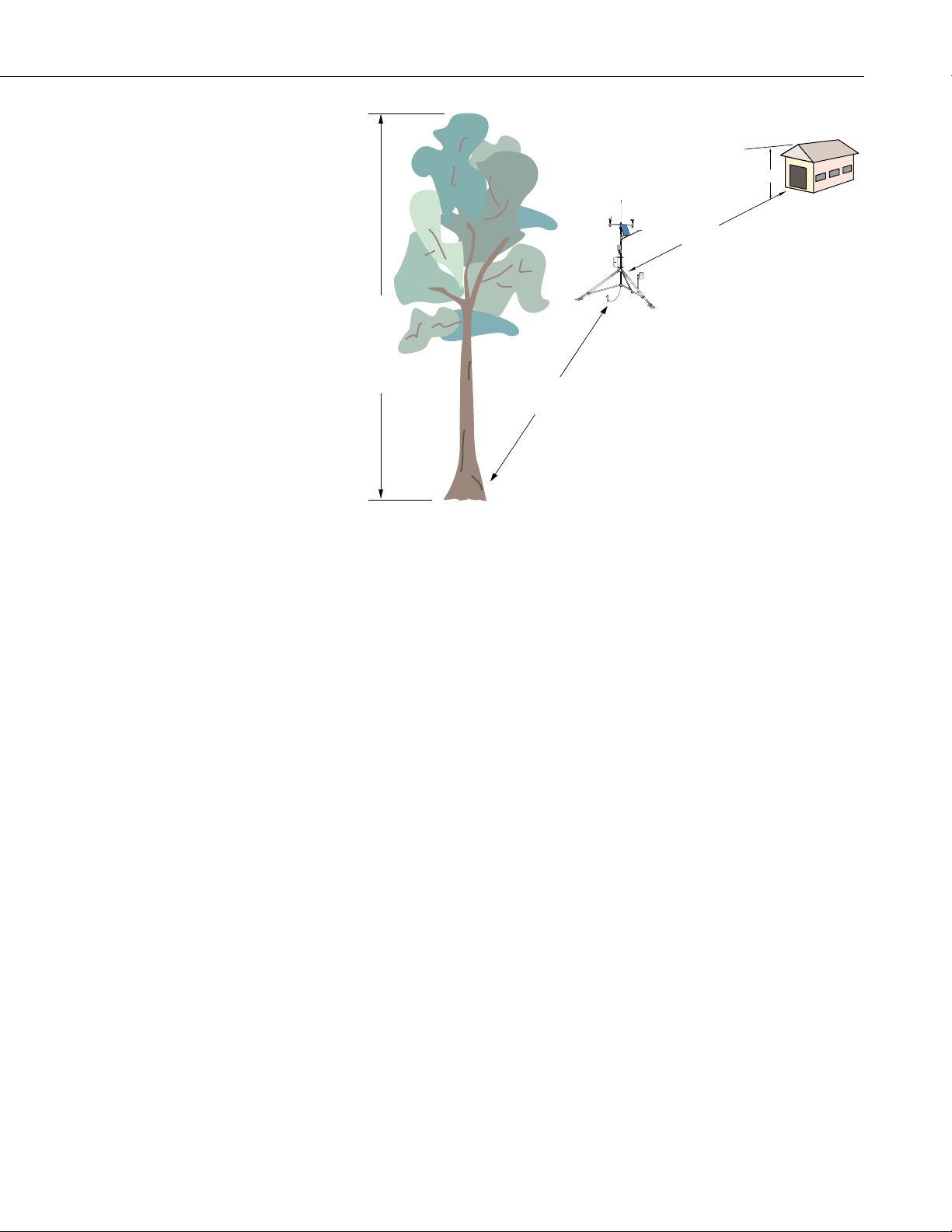
1.3.1 Wind Speed and Direction
Wind sensors should be located over open level terrain, and at a distance of at
least ten times (EPA) the height of any nearby building, tree or other
obstruction, as illustrated in Figure 1.3-1.
Standard measurement heights:
3.0 m ± 0.1 m recommended (AASC)
2.0 m ± 0.1 m, 10.0 m ± 0.5 m optional (AASC)
10.0 m (WMO and EPA)
1
, WMO (1983)2, and AASC (1985)3 publications.
1.3.2 Temperature and Relative Humidity
Sensors should be located over an open level area at least 9 m (EPA) in
diameter. The surface should be covered by short grass, or where grass does
not grow, the natural earth surface. Sensors should be located at a distance of
at least four times the height of any nearby obstruction and at least 30 m (EPA)
from large paved areas. Sensors should be protected from thermal radiation,
and adequately ventilated.
Situations to avoid include:
• large industrial heat sources
• rooftops
• steep slopes
• sheltered hollows
• high vegetation
• shaded areas
• swamps
• areas where snow drifts occur
• low places holding standing water after rains
1-5

Section 1. Preparation and Siting
1.3.3 Precipitation
Standard measurement heights:
1.5 m ± 1.0 m (AASC)
1.25 - 2.0 m (WMO)
2.0 m temperature (EPA)
2.0 m and 10.0 m for temperature difference (EPA)
A rain gage should be sited on level ground that is covered with short grass or
gravel. In open areas, the distance to obstructions should be two to four times
(EPA, AASC) the height of the obstruction.
The height of the opening should be as low as possible, but should be high
enough to avoid splashing from the ground. Wind shields, such as those used
by the National Weather Service, are recommended for open areas.
Collectors should be heated, if necessary, to properly measure frozen
precipitation. The gage must be mounted above the average level of snow
accumulation in areas that experience significant snowfall.
Standard measurement heights:
1.0 m ± 1.0 cm (AASC)
30.0 cm minimum (WMO, EPA)
1.3.4 Solar Radiation
Pyranometers should be located to avoid shadows on the sensor at any time.
Mounting it on the southern most (northern hemisphere) portion of the weather
station will minimize the chance of shading from other weather station
structures. Reflective surfaces and sources of artificial radiation should be
avoided. The height at which the sensor is mounted is not critical.
1.3.5 Soil Temperature
The measurement site for soil temperature should be at least 1 m2 and typical of
the surface of interest. The ground surface should be level with respect to the
immediate area (10 m radius).
Standard measurement depths:
10.0 cm ± 1.0 cm (AASC)
5.0 cm, 10.0 cm, 50.0 cm, 100.0 cm (WMO)
1-6
Section 1. Preparation and Siting
REGCOMENDED
FeedSENSORS
PortlandOr USA
Serial
27115
REGCOMENDED
FeedSENSORS
PortlandOr USA
Serial
27115
REGCOMENDED
FeedSENSORS
PortlandOr USA
Serial2711527115
H
10H
10T
Height of tree (T)
FIGURE 1.3-1. Effect of Structure on Wind Flow
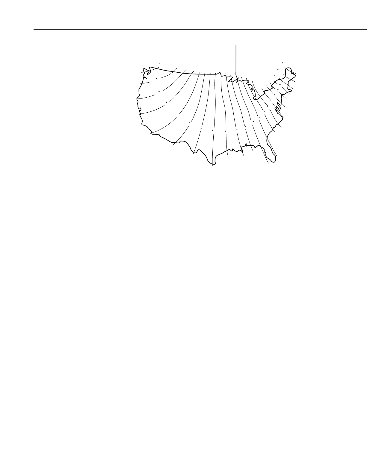
1.4 Determining True North for Wind Vane Orientation
Magnetic declination, or other methods to find True North, should be determined
prior to installing the weather st ation. True North is usually found by reading a
magnetic compass and applying the correction for magnetic declination*; where
magnetic declination is the number of degrees between True North and Magnetic
North. Magnetic declination for a specific site can be obtained from a USFA map,
local airpo rt, or through an internet service call ed NSSDC CGM (Section 1.4.1). A
general map showing magnetic declination for the contiguous United States is
shown in Figure 1.4-1.
Declination angles east of True North are considered negative, and are subtracted
from 0 degrees t o get True North as shown Figure 1.4-2. Declination angles west
of True North are con-sidered positive, and are added to 0 degrees to get True
North as shown in Figure 1.4-3. For example, the declination for Logan, Utah is
14.5° East. True North is 360° - 14.5°, or 345.5° as read on a compass.
* Other methods employ observations using the North Star or the sun, and
are discussed in the Quality Assurance Handbook for Air Pollution
Measurement Systems, Volume IV - Meteorological Measurements
4
.
1-7
Section 1. Preparation and Siting
Subtract declination from 360° Add declination to 0°
22 E
20 E
18 E
FIGURE 1.4-1. Magnetic Declination for the Contiguous United States
1.4.1 NSSDC CGM Service
The NSSDC CGM (Corrected Geomagnetic) Service provides an easy way of
determining magnetic declination of a specific site. Since magnetic declination
fluctuates with time, it should be determined each time the wind vane
orientation is adjusted. It can be accessed on the world wide web at
16 E
14 E
12 E
10 E
8 E
6 E
4 E
2 E
20 W
18 W
16 W
14 W
12 W
10 W
8 W
6 W
4 W
2 W
0
http://nssdc.gsfc.nasa.gov/space/cgm/cgm.html
If you know the latitude and longitude of your site, fill out Form 1as shown
below for an accurate magnetic declination. If you do not know the latitude
and longitude of your site, fill out Form 2 for estimate of magnetic declination.
Note that longitude is expressed in 0 to 360 degrees east of the Greenwich
prime meridian, and that north latitudes are positive.
Query Form 1: Latitude/Longitude
Latitude/Longitude below specified in: Geographic
Year (from 1945 to 2000): 1998
Altitude above Earth's surface (km) [from 0. to 40000.]: 0
Latitude (degrees) [from -90.00 to 90.00]: 42.03
Longitude (degrees) [from 0.00 to 360.00]: 248.15
Query Form 2: Image Map
Year (from 1945 to 2000): 1998
Altitude above Earth's surface (km) [0. - 40000.]: 0
Click on map to specify location and submit: (select area on map provided)
A table containing similar information to the following will be returned after
submitting Forms 1 or 2.
1-8

Section 1. Preparation and Siting
Geographic Alt. CGM IGRF Magnetic Field Dipole
Lat. Long. (km) Lat. Long. H(nT) D(deg) Z(nt) Lat. Long.
42.03 248.15 0. 49.80 311.06 20608. 14.417 50505. 49.68 312.14
Magnetic declination is bold in this example to show its location in the table. A
positive declination is east, while a negative declination is west. The
declination in this example is 14.417 degrees. As shown in Figure 1.4-1, the
declination for Logan, UT is east, so True North for this site is 360 - 14.417, or
345.5 degrees.
FIGURE 1.4-2. Declination Angles East of True North Are
Subtracted From 0 to Get True North
FIGURE 1.4-3. Declination Angles West of True North Are
Added to 0 to Get True North
1-9

Section 1. Preparation and Siting
References
1
EPA, (1987). On-Site Meteorological Program Guidance for Regulatory
Modeling Applications, EPA-450/4-87-013. Office of Air Quality Planning
and Standards, Research Triangle Park, North Carolina 27711.
2
WMO, (1983). Guide to Meteorological Instruments and Methods of
Observation. World Meteorological Organization No. 8, 5th edition, Geneva,
Switzerland.
3
The State Climatologist, (1985) Publication of the American Association of
State Climatologists: Height and Exposure Standards for Sensors on Automated
Weather Stations, v. 9, No. 4 October, 1985.
4
EPA, (1989). Quality Assurance Handbook for Air Pollution Measurement
Systems, EPA Office of Research and Development, Research Triangle Park,
North Carolina 27711.
1-10
Section 2. ET Tower Installation
DANGER: Do not install near power lines. If any part of the tower comes in contact with
power lines you could be KILLED. Contact local utilities for the location of buried utility
lines before digging or driving grounding rods.
CAUTION: Do not fit the 3 meter ET Tower sections together until the appropriate time.
Once attached, they cannot be detached.
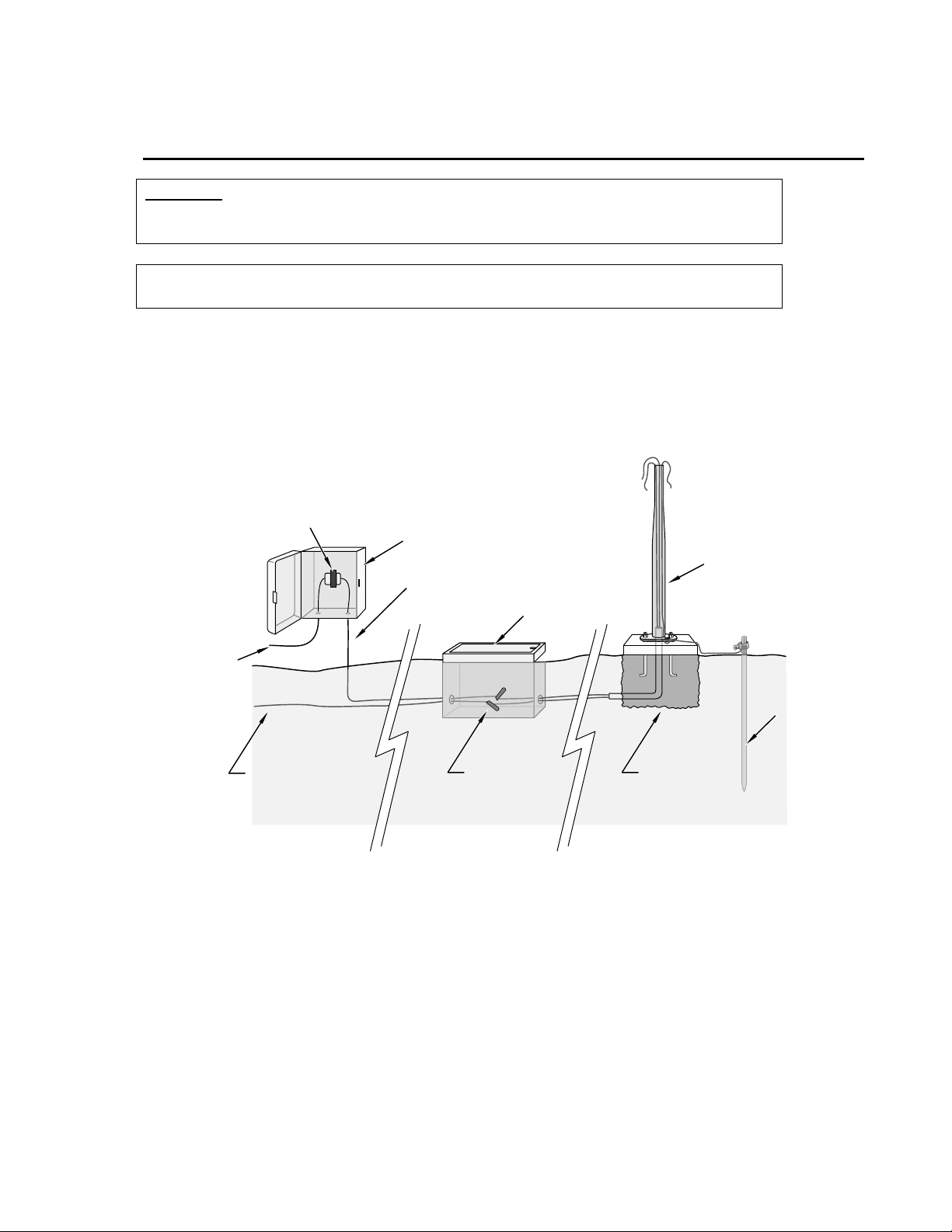
The ET Tower provides a support structure for mounting the ET101 and ET106 weather
station components. Figure 2.1-1 shows a typical ET Tower installation option. The
tower is designed to withstand winds of 100 mph. The lightning rod assembly is attached
after the instrumentation enclosure is installed (Section 3.1).
Transformer
110 VAC
Communications
Line
User Supplied
Junction Box
FIGURE 2.1-1. ET Tower Installation
2.1 Base Installation
16 VAC
Power
Valve Box
Direct Bury
Splices
ET Tower
Ground
Rod
Concrete
Base
2.1.1 Supplied Components
(3) ½ inch L-Bolts
(9) ½ inch Nuts
(1) Anchor Template
Refer to Section 1 for components supplied by installer.
2-1

Section 2. ET Tower Installation
2.1.2 Installation
1. The ET Tower attaches to a user supplied concrete foundation constructed
as shown in Figure 2.1-2.
2. Construct the concrete form with 2" x 4" lumber and 16p nails.
3. Assemble the template and anchor bolts. There should be two nuts below
and one nut above the template on each bolt.
4. Clear an area large enough to set the form at the desired elevation.
5. Dig a hole 2 feet x 2 feet x 2 feet. Lighter soils may require a deeper hole.
About 20 inches below the top of the hole, gouge a small cavity in one wall
of the hole. The cavity should be about 4 inches deep and just large
enough in diameter t o insert one end of the conduit. Make certai n the
cavity "points" in the direction from which power and communications
cables will come.
6. Center the form over the hole. Adjacent to the form, drive four stakes into
the soil. Secure the leveled form to the stakes with the 8p nails.
7. Cap the ends of the conduit with duct tape. Position the conduit and wire
into place by securing the wire to nails in the form.
8. Fill the hole and form with approximately ½ yard of concrete. Screed the
concrete level with the top of the form. Center the template assembly over
the conduit and press into the concrete. Put 2 x 4 spacers between the
template and the top of the form. The bottom of the bolt threads should be
about ½ inch above the concrete. The template must be level in two
dimensions. Use a trowel and edger to finish.
9. Wait 24 hours before removing the concr ete form. Wait 7 days befor e
mounting the ET Tower.
2-2
 Loading...