

Page 1

CR10 MEASUREMENT AND CONTROL MODULE
OPERATOR'S MANUAL
REVISION: 3/96
COPYRIGHT (c) 1987-1996 CAMPBELL SCIENTIFIC, INC.
Page 2

This is a blank page.
Page 3

WARRANTY AND ASSISTANCE
The CR10 MEASUREMENT AND CONTROL MODULE is warranted by CAMPBELL SCIENTIFIC, INC.
to be free from defects in materials and workmanship under normal use and service for thirty-six (36)
months from date of shipment unless specified otherwise. Batteries have no warranty. CAMPBELL
SCIENTIFIC, INC.'s obligation under this warranty is limited to repairing or replacing (at CAMPBELL
SCIENTIFIC, INC.'s option) defective products. The customer shall assume all costs of removing,
reinstalling, and shipping defective products to CAMPBELL SCIENTIFIC, INC. CAMPBELL SCIENTIFIC,
INC. will return such products by surface carrier prepaid. This warranty shall not apply to any
CAMPBELL SCIENTIFIC, INC. products which have been subjected to modification, misuse, neglect,
accidents of nature, or shipping damage. This warranty is in lieu of all other warranties, expressed or
implied, including warranties of merchantability or fitness for a particular purpose. CAMPBELL
SCIENTIFIC, INC. is not liable for special, indirect, incidental, or consequential damages.
Products may not be returned without prior authorization. To obtain a Returned Materials Authorization
(RMA), contact CAMPBELL SCIENTIFIC, INC., phone (435) 753-2342. After an applications engineer
determines the nature of the problem, an RMA number will be issued. Please write this number clearly
on the outside of the shipping container. CAMPBELL SCIENTIFIC's shipping address is:
CAMPBELL SCIENTIFIC, INC.
RMA#_____
815 West 1800 North
Logan, Utah 84321-1784
CAMPBELL SCIENTIFIC, INC. does not accept collect calls.
Non-warranty products returned for repair should be accompanied by a purchase order to cover the
repair.
Page 4

This is a blank page.
Page 5

CR10 MEASUREMENT AND CONTROL MODULE
TABLE OF CONTENTS
PAGE
OV1. PHYSICAL DESCRIPTION
OV1.1 Wiring Panel........................................................................................................................ OV-1
OV1.2 Connecting Power to the CR10
OV2. MEMORY AND PROGRAMMING CONCEPTS
OV2.1 Internal Memory..................................................................................................................OV-5
OV2.2 CR10 Instruc
OV2.3 Program Tables, Execution Interval and Output Intervals
tion Types ......................................................................................................OV-7
OV3. COMMUNICATING WITH CR10
OV3.1 CR10 Keyboard/Display......................................................................................................OV-9
OV3.2 Using the PC208 Terminal Emulator (GraphTerm)............................................................
OV3.3 ASCII Terminal or Computer with Terminal Emulator
OV4. PROGRAMMING THE CR10
OV4.1 Functional Modes.............................................................................................................. OV-10
OV4.2 Key Definition
OV4.3 Programming Sequence...................................................................................................
OV4.4 Instruction Format
OV4.5 Entering a Program...........................................................................................................
....................................................................................................................OV-10
.............................................................................................................OV-11
..........................................................................................OV-5
..................................................OV-7
OV-9
........................................................OV-9
OV-11
OV-12
OV5. PROGRAMMING EXAMPLES
OV5.1 Sample Program 1............................................................................................................ OV-13
OV5.2 Sample Program 2
OV5.3 Editing an Exis
............................................................................................................OV-14
ting Program..............................................................................................OV-15
OV6. DATA RETRIEVAL OPTIONS.................................................................................... OV-17
OV7. SPECIFICATIONS..........................................................................................................OV-20
PROGRAMMING
1. FUNCTIONAL MODES
1.1 Program Tables - *1, *2, and *3 Modes................................................................................. 1-1
1.2 Setting and Displaying the Clock - *5 Mode
1.3 Displaying/Altering Input Memory, Flags, and Ports - *6 Mode
1.4 Compiling and Logging Data - *0 Mode
1.5 Memory Alloc
1.6 Memory Testing and System Status - *B
1.7 *C Mode -- Security
1.8 *D Mode -- Save or Load Program
ation - *A .......................................................................................................... 1-4
................................................................................................................ 1-7
........................................................................................ 1-7
.......................................................................... 1-2
............................................. 1-3
................................................................................. 1-4
............................................................................... 1-6
Page 6

CR10 TABLE OF CONTENTS
2. INTERNAL DATA STORAGE
2.1 Final Storage Areas, Output Arrays, and Memory Pointers .................................................. 2-1
2.2 Data Output Format and Range Limits
2.3 Displaying Stored Data on Keyboard/Display - *7 Mode.......................................................
.................................................................................. 2-3
2-3
3. INSTRUCTION SET BASICS
3.1 Parameter Data Types........................................................................................................... 3-1
3.2 Repetitions
3.3 Entering Negative Numbers
3.4 Indexing Input Locations and Ports
3.5 Voltage Range and Overrange Detection
3.6 Output Proc
3.7 Use of Flags: Output and Program Control ..........................................................................
3.8 Program Control Logical Constructions
3.9 Instruction Memory and Execution Time
3.10 Error Codes
............................................................................................................................. 3-1
................................................................................................... 3-1
....................................................................................... 3-1
.............................................................................. 3-2
essing ................................................................................................................. 3-2
3-3
................................................................................. 3-4
............................................................................... 3-5
............................................................................................................................ 3-8
DATA RETRIEVAL/COMMUNICATION
4. EXTERNAL STORAGE PERIPHERALS
4.1 On-Line Data Transfer - Instruction 96.................................................................................. 4-1
4.2 Manually Initiated Data Output - *8 Mode
4.3 Cassette Tape Option
4.4 Printer Output Formats
4.5 Storage Module (SM192/716)
4.6 *9 Mode -- Storage Module Commands
............................................................................................................ 4-3
.......................................................................................................... 4-5
................................................................................................ 4-6
.............................................................................. 4-3
................................................................................ 4-7
5. TELECOMMUNICATIONS
5.1 Telecommunications Commands .......................................................................................... 5-1
5.2 Remote Programming of the CR10
....................................................................................... 5-4
6. 9-PIN SERIAL INPUT/OUTPUT
6.1 Pin Description....................................................................................................................... 6-1
6.2 Enabling and Addressing Peripherals
6.3 Ring Interrupts
6.4 Interrupts During Data Trans
6.5 Modem/Terminal Peripherals
6.6 Synchronous Device Communication
6.7 Modem/Terminal and Computer Requirements
........................................................................................................................ 6-3
fer............................................................................................. 6-3
................................................................................................. 6-4
.................................................................................... 6-2
.................................................................................... 6-4
.................................................................... 6-5
ii
Page 7

CR10 TABLE OF CONTENTS
PROGRAM EXAMPLES
7. MEASUREMENT PROGRAMMING EXAMPLES
7.1 Single-Ended Voltage - LI200S Silicon Pyranometer............................................................ 7-1
7.2 Differential Voltage Measurement
7.3 Thermocouple Temperatures Using the Optional CR10TCR to Measure
the Referenc
7.4 Thermocouple Temperatures Using an External Reference Junction
7.5 107 Temperature Probe
7.6 207 Temperature and RH Probe
7.7 Anemometer with Photochopper Output................................................................................
7.8 Tipping Bucket Rain Gage with Long Leads .........................................................................
7.9 100 ohm PRT in 4 Wire Half Bridge
7.10 100 ohm PRT in 3 Wire Half Bridge
7.11 100 ohm PRT in 4 Wire Full Bridge
7.12 Pressure Transducer - 4 Wire Full Bridge ...........................................................................
7.13 Lysimeter - 6 Wire Full Bridge
7.14 227 Gypsum Soil Moisture Block
7.15 Nonlinear Thermistor in Half Bridge (Model 101 Probe) .....................................................
7.16 Water Level - Geokon's Vibrating Wire Pressure Sensor
7.17 Paroscientific "T" Series Pres
7.18 SDM Peripherals
7.19 Paroscientific Pressure Trans
e Temperature................................................................................................... 7-3
......................................................................................................... 7-4
.................................................................................................................. 7-24
......................................................................................... 7-2
.................................. 7-3
........................................................................................... 7-4
7-5
7-6
....................................................................................... 7-6
....................................................................................... 7-8
....................................................................................... 7-9
7-10
............................................................................................. 7-11
......................................................................................... 7-13
7-14
.................................................... 7-15
sure Transducer.................................................................... 7-19
ducer Processing.................................................................. 7-24
8. PROCESSING AND PROGRAM CONTROL EXAMPLES
8.1 Computation of Running Average.......................................................................................... 8-1
8.2 Rainfall Intens
8.3 Using Control Ports and Loop to Run AM416 Multiplexer
8.4 Sub 1 Minute Output Interval Synched to Real Time
8.5 Interrupt Subroutine Used to Count Switch Closures (Rain Gage)
8.6 SDM-A04 Analog Output Multiplexer to Strip Chart ..............................................................
8.7 Converting 0-360 Wind Direction Output to 0-540 for Strip Chart
8.8 Use of 2 Final Storage Areas - Saving Data Prior to Event
8.9 Logarithmic Sampling Using Loops
ity..................................................................................................................... 8-2
..................................................... 8-3
............................................................ 8-5
....................................... 8-5
8-7
......................................... 8-8
................................................... 8-9
..................................................................................... 8-10
INSTRUCTIONS
9. INPUT/OUTPUT INSTRUCTIONS........................................................................................ 9-1
10. PROCESSING INSTRUCTIONS...................................................................................... 10-1
11. OUTPUT PROCESSING INSTRUCTIONS................................................................... 11-1
12. PROGRAM CONTROL INSTRUCTIONS...................................................................... 12-1
iii
Page 8

CR10 TABLE OF CONTENTS
MEASUREMENTS
13. CR10 MEASUREMENTS
13.1 Fast and Slow Measurement Sequence.............................................................................. 13-1
13.2 Single-Ended and Differential Voltage Measurements
13.3 The Effect of Sensor Lead Length on the Signal Settling Time...........................................
13.4 Thermocouple Measurements
13.5 Bridge Resistance Measurements
13.6 Resistance Measurements Requiring AC Excitation.........................................................
13.7 Calibration Proces
s............................................................................................................ 13-22
........................................................................................... 13-12
..................................................................................... 13-17
........................................................ 13-2
13-3
13-21
INSTALLATION
14. INSTALLATION AND MAINTENANCE
14.1 Protection from the Environment ......................................................................................... 14-1
14.2 Power Requirements
14.3 Campbell Scientific Power Supplies
14.4 Solar Panels
14.5 Direct Battery Connection to the CR10WP Wiring Panel....................................................
14.6 Vehicle Power Supply Connections
14.7 Grounding ............................................................................................................................
14.8 Wiring Panel
14.9 Switched 12 Volt
14.10 Use of Digital I/O Ports
14.11 Maintenance
......................................................................................................................... 14-5
......................................................................................................................... 14-7
......................................................................................................................... 14-9
........................................................................................................... 14-1
.................................................................................... 14-2
14-5
..................................................................................... 14-5
14-6
.................................................................................................................. 14-7
for Switching Relays....................................................................... 14-7
APPENDICES
A. GLOSSARY ................................................................................................................................A-1
B. CR10 PROM SIGNATURE AND OPTIONAL SOFTWARE
B.1 PROM Signature and Version................................................................................................B-1
B.2 Available PROMs/Library Options
B.3 Description of Library Options Not in Standard Manual ........................................................
C. BINARY TELECOMMUNICATIONS
C.1 Telecommunications Command with Binary Responses......................................................C-1
C.2 Final Storage Format
C.3 Generation of Signature
.............................................................................................................C-2
.........................................................................................................C-4
D. CR10 37 PIN PORT DESCRIPTION................................................................................D-1
E. ASCII TABLE...........................................................................................................................E-1
G. CHANGING RAM OR PROM CHIPS
G.1 Disassembling the CR10 .......................................................................................................G-1
G.2 Installing New RAM Chips in CR10s
G.3 Installing New PROM
G.4 Installing 4K Program Memory PROM
.............................................................................................................G-1
.........................................................................................B-1
B-2
with 16K RAM .............................................................G-1
...................................................................................G-1
iv
Page 9

CR10 TABLE OF CONTENTS
LIST OF TABLES..........................................................................................................................LT-1
LIST OF FIGURES........................................................................................................................LF-1
INDEX................................................................................................................................................... I-1
v
Page 10

CR10 TABLE OF CONTENTS
This is a blank page.
vi
Page 11

SELECTED OPERATING DETAILS
1. Storing Data - Data are stored in Final
Storage only by Output Processing
Instructions and only when the Output Flag
is set. (Sections OV4.1.1 and OV4.2.1)
2. Storing Date and Time - Date and time
are stored with the data in Final Storage
ONLY if the Real Time Instruction 77 is
used. (Section 11)
3. Data Transfer - On-line data transfer from
Final Storage to peripherals (printer,
Storage Module, etc.) occurs only if
enabled with Instruction 96 in the
datalogger program. (Sections 4 and 12)
4. Final Storage Resolution - All Input
Storage values are displayed (*6 mode) as
high resolution with a maximum value of
99999. However, the default resolution for
data stored in Final Storage is low
resolution, maximum value of 6999.
Results exceeding 6999 are stored as 6999
unless Instruction 78 is used to store the
values in Final Storage as high resolution
values. (Sections 2.2.1 and 11)
7. ALL memory
can be erased and the
CR10 completely reset by entering 1986 for
the number of bytes left in Program
Memory. (Section 1.5.2)
8. The set of instructions available in the
CR10 is determined by the PROM
(Programmable Read Only Memory) that it
is equipped with. Standard and optional
software are identified in Appendix B. If
you have ordered optional software that is
not covered in the standard manual, the
documentation is in Appendix H.
9. Radiotelemetry
Users - As of February,
1990, CR10 PROMs no longer contain
radio frequency interface software. That
function is now contained in the RF95
Modem. To make measurements at a
phone-to-RF base station using the
RF100/RF200 Radio and RF95 Modem,
current CR10 software is required. A CR10
with old software can be used with the new
RF95 in the "RF95-ME" state, but the
datalogger loses the "callback" capability as
well as the SDC function.
5. Floating Point Format - The computations
performed in the CR10 use floating point
arithmetic. CSI's 4 byte floating point
numbers contain a 23 bit binary mantissa
and a 6 bit binary exponent. The largest
and smallest numbers that can be stored
and processed are 9 x 10
18
and 1 x 10
-19
,
respectively. (Section 2.2.2)
6. Erasing Final Storage - Data in Final
Storage can be erased without altering the
program by using the *A Mode to repartition
memory. (Section 1.5.2)
10. Changes w
ith the release of OS10-0.1:
Wind Vector Instruction 69 has replaced
Instruction 76. The options to do subinterval averaging of the standard deviation
of wind direction, σ(θ), and to calculate σ(θ)
using the Yamartino algorithm have been
added to the previous options (Section 9).
Intermediate Processing Disable Flag 9
in now set low if a conditional test for
setting it high fails (same as Output Flag 0,
Section 3.7.2).
*D options for saving and loading
programs w
ith a cassette tape are no
longer in a standard PROM and must be
ordered as a library option PROM
(Appendix B).
vi
Page 12

CAUTIONARY NOTES
1. Damage will occur to the analog input
circuitry if voltages in excess of ±16 V are
applied for a sustained period. Voltages in
excess of ±5V will cause errors and
possible overranging on other analog input
channels.
2. When using the CR10 with the PS12LA,
remember that the sealed lead acid
batteries are permanently damaged if
discharged below 10.5 V. The cells are
rated at a 7 Ahr capacity but experience a
slow discharge even in storage. It is
advisable to maintain a continuous charge
on the PS12LA battery pack, whether in
operation or storage (Section 14).
3. When connecting power to the CR10, first
connect the positive lead from the power
source to the 12 V terminal. Then connect
the negative lead to G. Connecting these
leads in the reverse order creates the
possibility of a short (Section 14).
4. There are frequent references in this
manual to Storage Modules. The Storage
Modules referred to are the SM192 and
SM716. The old SM16 and SM64 Storage
Modules will NOT work with the CR10
without a specially modified cable. In
addition, the SM16 and SM64 cannot
perform many of the functions that the
SM192 and SM716 are capable of
performing.
5. Voltages in excess of 5.5 volts applied to a
control port can cause the CR10 to
malfunction.
6. Voltage pulses can be counted by CR10
Pulse Counters configured for High
Frequency Pulses. However, when the
pulse is actually a low frequency signal
(below about 10 Hz) AND the positive
voltage excursion exceeds 5.6 VDC, the 5
VDC supply will start to rise, upsetting all
analog measurements.
Pulses whose positive voltage portion
exceed 5.6 VDC with a duration longer than
100 milliseconds need external
conditioning. See the description of the
Pulse count instruction in Section 9 for
details on the external conditioning.
7. The CR10 module is sealed and contains
desiccant to protect against excess
humidity. The Wiring Panel and the
connections between the Wiring Panel and
the CR10 are still susceptible to humidity.
To prevent corrosion at these points,
additional desiccant must be placed inside
the enclosure. To reduce vapor transfer
into the enclosure, plug the cable entry
conduit with Duct Seal, a putty-type sealant
available at most electrical supply houses.
DO NOT totally seal enclosures equipped
with lead acid batteries. Hydrogen
concentration may build up to explosive
levels.
vii
Page 13

CR10 MEASUREMENT AND CONTROL MODULE OVERVIEW
Campbell Scientific Inc. provides four aids to understanding and operating the CR10:
1. PCTOUR
This Overview
2.
3. The CR10 Operator's Manual
4. The CR10 Prompt Sheet
PCTOUR is a computer-guided tour of CR10 operation and the use of the PC208 Datalogger Support
Software. Muc
included with every datalogger or PC208 order.
This Overview introduces the concepts required to take advantage of the CR10's capabilities. Handson program
don't just read the examples, do them. If you want to start this minute, go ahead and try the examples,
then come back and read the rest of the Overview.
h of the material in this Overview is covered in PCTOUR. A copy of PCTOUR is
ming examples start in Section OV5. Working with a CR10 will help the learning process, so
The sections of the Operator's Manual which should be read to com
CR10 operation are the Programming Sections 1-3, the portions of the data retrieval Sections 4 and 5
appropriate to the method(s) you are using (see OV6), and Section 14 which covers installation and
maintenance.
Section 6 covers details of serial communications. Sections 7 and 8 contain program
Sections 9-12 have detailed descriptions of each programming instruction, and Section 13 goes into
detail on the CR10 measurement procedures.
The Prompt Sheet is an abbreviated description of the program
CR10, it is possible to program it using only the Prompt Sheet as a reference, consulting the manual if
further detail is needed.
Read the Selected Operating Details and Cautionary Notes at the front of the Manual before using the
CR10.
OV1. PHYSICAL DESCRIPTION
The CR10 is a fully programmable
datalogger/controller in a small, rugged, sealed
module. Programming is very similar to
Campbell Scientific's 21X and CR7
dataloggers. Some fundamental physical
differences are listed below.
• The CR10 does not have an integral
keyboard/display. The user accesses the
CR10 with the portable CR10KD Keyboard
Display or with a computer or terminal
(Section OV2).
• The CR10 does not have an integral
terminal strip. A removable wiring panel
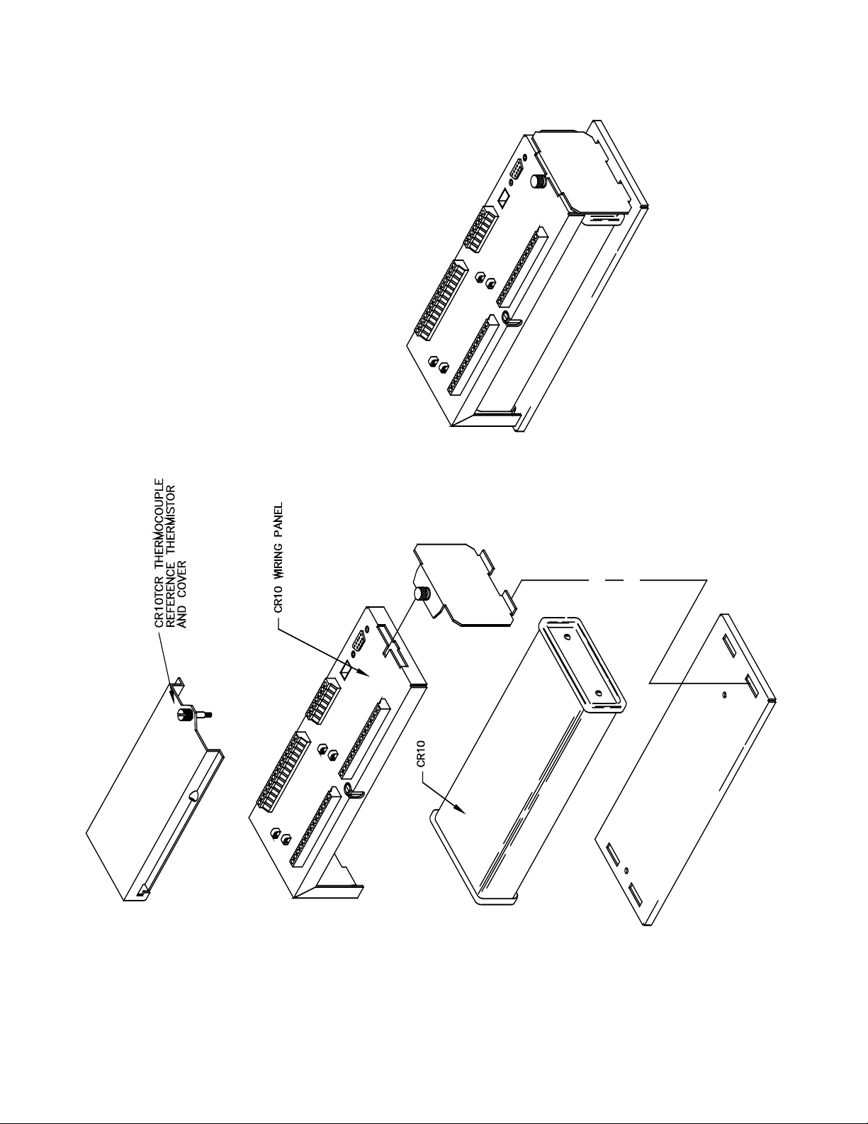
(Figure OV1.1-1) performs this function and
attaches to the two D-type connectors
located at the end of the module.
• The power supply is external to the CR10.
This gives the user a wide range of options
(Section 14) for powering the CR10.
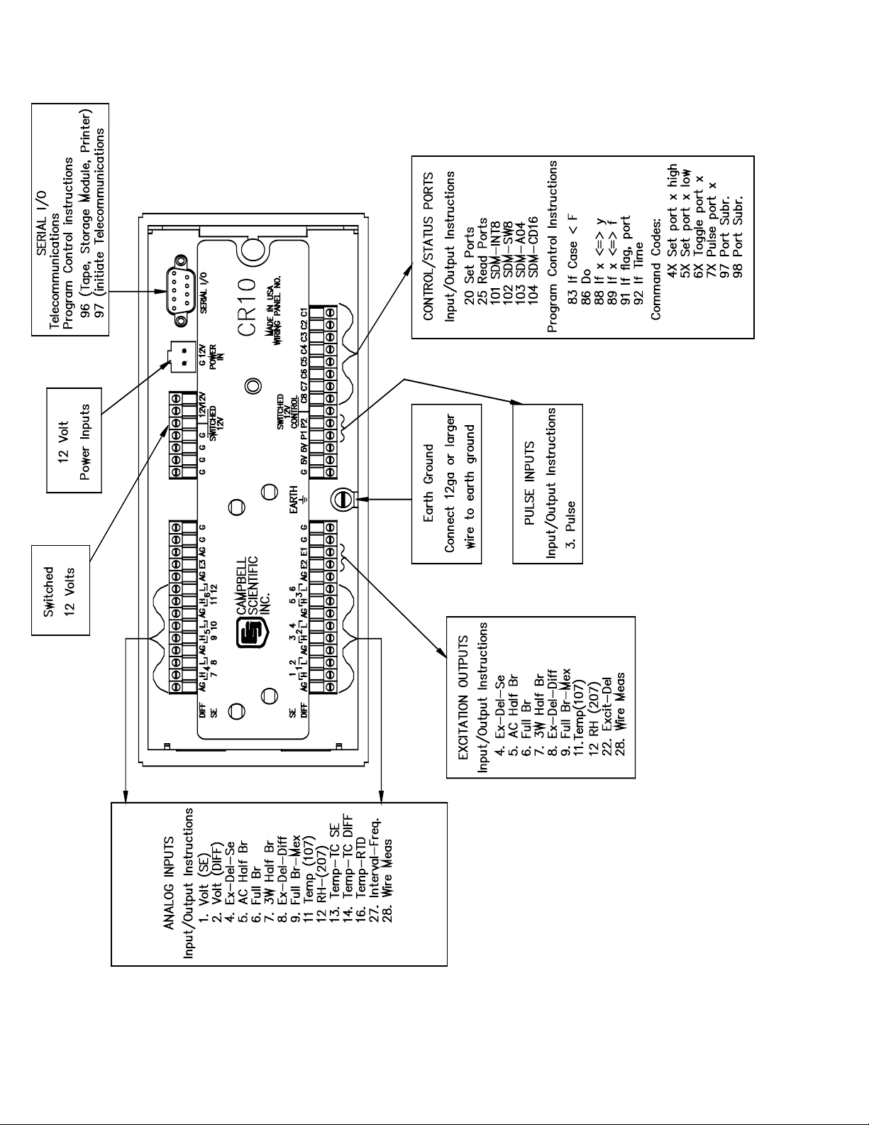
OV1.1 WIRING PANEL
The CR10 Wiring Panel and CR10 datalogger
make electrical contact through the two D-type
connectors at the (left) end of the CR10.
The Wiring Panel contains a 9-pin Serial I/O
port used when communicating with the
datalogger and provides terminals for
connecting sensor, control, and power leads to
the CR10. It also provides transient protection
and reverse polarity protection. Figure OV1.1-2
shows the panel and the instructions used to
access the various terminals.
plete a basic understanding of the
ming examples.
ming instructions. Once familiar with the
OV-1
Page 14
CR10 OVERVIEW
OV-2
Page 15

FIGURE OV1.1-1. CR10 and Wiring Panel
CR10 OVERVIEW
OV-3
Page 16
CR10 OVERVIEW
OV-4
FIGURE OV1.1-2. CR10 Wiring Panel/Instruction Access
Page 17

CR10 OVERVIEW
OV-5
Page 18

CR10 OVERVIEW
OV1.1.1 ANALOG INPUTS
The terminals labeled 1H to 6L are analog
inputs. These numbers refer to the high and
low inputs to the differential channels 1 through
6. In a differential measurement, the voltage on
the H input is measured with respect to the
voltage on the L input. When making singleended measurements, either the H or L input
may be used as an independent channel to
measure voltage with respect to the CR10
analog ground (AG). The single-ended
channels are numbered sequentially starting
with 1H; e.g., the H and L sides of differential
channel 1 are single-ended channels 1 and 2;
the H and L sides of differential channel 2 are
single-ended channels 3 and 4, etc. (The
single-ended channel numbers do NOT appear
on older wiring panels).
OV1.1.2 SWITCHED EXCITATION OUTPUTS
The terminals labeled E1, E2, and E3 are
precision, switched excitation outputs used to
supply programmable excitation voltages for
resistive bridge measurements. DC or AC
excitation at voltages between -2500 mV and
+2500 mV are user programmable (Section 9).
OV1.1.3 PULSE INPUTS
The terminals labeled P1 and P2 are the pulse
counter inputs for the CR10. They are
programmable for switch closure, high
frequency pulse or low level AC (Section 9,
Instruction 3).
OV1.1.4 DIGITAL I/O PORTS
Terminals C1 through C8 are digital
Input/Output ports. On power-up they are
configured as input ports, commonly used for
reading the status of an external signal. High
and low conditions are: 3V < high < 5.5V; -0.5V
< low < 0.
8V.
Configured as outputs the ports allow on/off
control of external devices. A port can be set
high (5V ± 0.1V), set low (<0.1V), toggled or
pulsed (Sections 3, 8.3, and 12).
OV1.1.5 ANALOG GROUND (AG)
The AG terminals are analog grounds, used as
the reference for single-ended measurements
and excitation return.
OV1.1.6 12V AND POWER GROUND (G)
TERMINALS
The 12V and power ground (G) terminals are
used to supply 12V DC power to the
datalogger. The extra 12V and G terminals can
be used to connect other devices requiring 12V
power.
The G terminals are also used to tie cable
shields to ground, and to provide a ground
reference for pulse counters and binary inputs.
For protection against transient voltage spikes,
power ground should be connected to a good
earth ground (Section 14.3.1).
OV1.1.7 5V OUTPUTS
The two 5V (±0.2%) outputs are commonly
used to power peripherals such as the QD1
Incremental Encoder Interface, AVW1 or AVW4
Vibrating Wire Interface.
The 5V outputs are common with pin 1 on the 9
pin serial connector; 200 mA is the maximum
combined output.
OV1.1.8 SERIAL I/O
The 9 pin serial I/O port contains lines for serial
communication between the CR10 and external
devices such as computers, printers, Storage
Modules, etc. This port does NOT hav
e the
same configuration as the 9 pin serial ports
currently used on many personal computers.
It has a 5VDC power line which is used to power
peripherals such as the SM192 or SM716
Storage Module or the DC112 Phone Modem.
The same 5VDC supply is used for the 5V
outputs on the lower terminal strip. Section 6
contains technical details on serial
communication.
OV1.1.9 SWITCHED 12 VOLT
Wiring panels introduced in March 1994 include
a switched 12 volt output. This can be used to
power sensors or devices requiring an
unregulated 12 volts. The output is limited to
600 mA current.
A control port is used to operate the switch.
Connect a wire from the control port to the
switched 12 volt control port. When the port is
set high, the 12 volts is turned on; when the
port is low, the switched 12 volts is off.
OV-6
Page 19

CR10 OVERVIEW
OV1.2 CONNECTING POWER TO THE CR10
The CR10 can be powered by any 12VDC
source. First connect the positive lead from the
power supply to one of the 12V terminals and
then connect the negative lead to one of the
power ground (G) terminals. The Wiring Panel
power connection is reverse polarity protected.
See Section 14 for details on power supply
connections.
CAUTION: The metal surfaces of the
CR10 Wiring Panel, and CR10KD
Keyboard Display are at the same potential
as power ground. To avoid shorting 12
volts to ground, connect the 12 volt lead
first, then connect the ground lead.
OV2. MEMORY AND PROGRAMMING
CONCEPTS
The CR10 must be programmed before it will
make any measurements. A program consists
of a group of instructions entered into a
program table. The program table is given an
execution interval which determines how
frequently that table is executed. When the
table is executed, the instructions are executed
in sequence from beginning to end. After
executing the table, the CR10 waits the
remainder of the execution interval and then
executes the table again starting at the
beginning.
The interval at which the table is executed
generally determines the interval at which the
sensors are measured. The interval at which
data are stored is separate from how often the
table is executed, and may range from samples
every execution interval to processed
summaries output hourly, daily, or on longer or
irregular intervals.
Figure OV2.1-1 represents the measurement,
processing, and data storage sequence, and
the types of instructions used to accomplish
hese tasks.
t
OV2.1 INTERNAL MEMORY
The CR10 has 64K bytes of Random Access
Memory (RAM), divided into five areas. The
use of the Input, Intermediate, and Final
Storage in the measurement and data
processing sequence is shown in Figure
OV2.1-1. While the total size of these three
areas remains constant, memory may be
reallocated between the areas to accommodate
different measurement and processing needs
(*A Mode, Section 1.5). The size of the 2
additional memory areas, system and program,
are fixed. The five areas of RAM are:
1. Input Storage - Input Storage holds the
results of measurements or calculations.
The *6 Mode is used to view Input Storage
locations for checking current sensor
readings or calculated values. Input
Storage defaults to 28 locations. Additional
locations can be assigned using the *A
Mode (Section 1.5).
2. Intermediate Storage - Certain Processing
Instructions and most of the Output
Processing Instructions maintain
intermediate results in Intermediate
Storage. Intermediate storage is
automatically accessed by the instructions
and cannot be accessed by the user. The
default allocation is 64 locations. The
number of locations can be changed using
the *A Mode.
3. Final Storage - Final processed values are
stored here for transfer to printer, solid
state Storage Module or for retrieval via
telecommunication links. Values are stored
in Final Storage only by the Output
Processing Instructions and only when the
Output Flag is set in the users program.
Approximately 29,900 locations are
allocated to Final Storage on power up.
This number is reduced if Input or
Intermediate Storage is increased.
4. Sy
stem Memory - used for overhead tasks
such as compiling programs, transferring
data etc. The user cannot access this
memory.
5. Program Memory - available for user
programs entered in program tables 1 and
2, and Subroutine Table 3.
OV-7
Page 20
CR10 OVERVIEW
INPUT/OUTPUT
INSTRUCTIONS
Sensors
Control
Specify the conversion of a sensor signal
to a data value and store it in Input
Storage. Programmable entries specify:
(1) the measurement type
(2) the number of channels to measure
(3) the input voltage range
(4) the Input Storage Location
(5) the sensor calibration constants
used to convert the sensor output to
engineering units
I/O Instructions also control analog
outputs and digital control ports.
INPUT STORAGE
Holds the results of measurements or
calculations in user specified locations.
The value in a location is written over
each time a new measurement or
calculation stores data to the locations.
OUTPUT PROCESSING
INSTRUCTIONS
Perform calculations over time on the
values updated in Input Storage.
Summaries for Final Storage are
generated when a Program Control
Instruction sets the Output Flag in
response to time or events. Results
may be redirected to Input Storage for
further processing. Examples include
sums, averages, max/min, standard
deviation, histograms, etc.
Output Flag set high
PROCESSING INSTRUCTIONS
Perform calculations with values in Input
Storage. Results are returned to Input
Storage. Arithmetic, transcendental and
polynomial functions are included.
INTERMEDIATE STORAGE
Provides temporary storage for intermediate
calculations required by the OUTPUT
PROCESSING INSTRUCTIONS; for
example, sums, cross products,
comparative values, etc.
OV-8
FINAL STORAGE
Final results from OUTPUT
PROCESSING INSTRUCTIONS are
stored here for on-line or interrogated
transfer to external devices (Figure
OV5.1-1). The newest data are stored
over the oldest in a ring memory.
FIGURE OV2.1-1. Instruction Types and Storage Areas
Page 21

CR10 OVERVIEW
OV2.2 CR10 INSTRUCTION TYPES
Figure OV2.1-1 illustrates the use of three
different instruction types which act on data.
The fourth type, Program Control, is used to
control output times and vary program
execution. Instructions are identified by
numbers.
1. INPUT/OUTPUT INSTRUCTIONS (1-28,
101-104, Section 9) control the terminal
strip inputs and outputs (the sensor is the
source, Figure OV1.1-2), storing the results
in Input Storage (destination). Multiplier
and offset parameters allow conversion of
linear signals into engineering units. The
Digital I/O Ports are also addressed with
tructions.
I/O Ins
2. PROCESSING INSTRUCTIONS (30-66,
Section 10) perform numerical operations
on values located in Input Storage (source)
and store the results back in Input Storage
(destination). These instructions can be
used to develop high level algorithms to
process measurements prior to Output
Processing.
3. OUTPUT PROCESSING INSTRUCTIONS
(69-82, Section 11) are the only
instructions which store data in Final
Storage (destination). Input Storage
(source) values are processed over time to
obtain averages, maxima, minima, etc.
There are two types of processing done by
Output Instructions: Intermediate and
Final.
Intermediate processing normally tak
place each time the instruction is executed.
For example, when the Average Instruction
is executed, it adds the values from the
input locations being averaged to running
totals in Intermediate Storage. It also keeps
track of the number of samples.
es
Final processing occurs only when the
Output Flag is high. The Output
Processing Instructions check the Output
Flag. If the flag is high, final values are
calculated and output. With the Average,
the totals are divided by the number of
samples and the resulting averages sent to
Final Storage. Intermediate locations are
zeroed and the process starts over. The
Output Flag, Flag 0, is set high by a
Program
Control Instruction which must
precede the Output Processing Instructions
in the user entered program.
4. PROGRAM CONTROL INSTRUCTIONS
(83-98, Section 12) are used for logic
decisions and conditional statements. They
can set flags, compare values or times,
execute loops, call subroutines, conditionally
execute portions of the program, etc.
OV2.3 PROGRAM TABLES, EXECUTION
INTERVAL AND OUTPUT INTERVALS
Programs are entered in Tables 1 and 2.
Subroutines, called from Tables 1 and 2, are
entered in Subroutine Table 3. The size of
each table is flexible, limited only by the total
amount of program memory. If Table 1 is the
only table programmed, the entire program
memory is available for Table 1.
Table 1 and Table 2 have independent
execution intervals, entered in units of seconds
with an allowable range of 1/64 to 8191
seconds. Subroutine Table 3 has no execution
interval; subroutines are only executed when
called from Table 1 or 2.
OV2.3.1 THE EXECUTION INTERVAL
The execution interval specifies how often the
program in the table is executed, which is
usually determined by how often the sensors
are to be measured. Unless two different
easurement rates are needed, use only one
m
table. A program table is executed sequentially
starting with the first instruction in the table and
proceeding to the end of the table.
OV-9
Page 22

CR10 OVERVIEW
Table 1.
Execute every x sec.
0.0156 < x < 8191
Instructions are executed
sequentially in the order they
are entered in the table.
One complete pass through
the table is made each
execution interval unless
program control instructions
are used to loop or branch
execution.
Normal Order:
MEASURE
PROCESS
CHECK OUTPUT COND.
OUTPUT PROCESSING
FIGURE OV2.3-1. Program and Subroutine Tables
Each instruction in the table requires a finite
time to execute. If the execution interval is less
than the time required to process the table, an
execution interval overrun occurs; the CR10
finishes processing the table and waits for the
next execution interval before initiating the
table. When an overrun occurs, decimal points
are shown on either side of the G on the display
in the LOG mode (*0). Overruns and table
priority are discussed in Section 1.1.
OV2.3.2. THE OUTPUT INTERVAL
Table 2.
Execute every y sec.
0.0156 < y < 8191
Table 2 is used if there is a
need to measure and
process data on a separate
interval from that in Table 1.
Table 3.
Subroutines
A subroutine is executed
only when called from Table
1 or 2.
Subroutine Label
Instructions
End
Subroutine Label
Instructions
End
Subroutine Label
Instructions
End
OV3. COMMUNICATING WITH CR10
An external device must be connected to the
CR10's Serial I/O port to communicate with the
CR10. This may be either Campbell Scientific's
portable CR10KD Keyboard Display or a
computer/terminal.
The CR10KD is powered by the CR10 and
connects directly to the serial port via the SC12
cable (supplied with the CR10KD). No
interfacing software is required.
The interval at which output occurs is
independent from the execution interval, other
than the fact that it must occur when the table is
executed (e.g., a table cannot have a 10 minute
execution interval and output every 15
minutes).
A single program table can have many different
output intervals and conditions, each with a
unique data set (Output Array). Program
Control Instructions are used to set the Output
Flag. The Output Processing Instructions
which follow the instruction setting the Output
Flag determine the data output and its
sequence. Each additional Output Array is
created by another Program Control Instruction
checking a output condition, followed by Output
Processing Instructions defining the data set to
output.
OV-10
To communicate with any device other than the
CR10KD, the CR10 enters its Telecommunications Mode and responds only to valid
telecommunications commands. Within the
Telecommunications Mode, there are 2 "states";
the Telecommunications Command state and the
Remote Keyboard state. Communication is
established in the Telecommunications command
state. One of the commands is to enter the
Remote Keyboard state.
The Remote Keyboard state allows the
keyboard of the computer/terminal to act like
the CR10KD keyboard. Various datalogger
modes may be entered, including the mode in
which programs may be keyed in to the CR10
from the computer/terminal.
Campbell Scientific's PC208 Datalogger
Support Software facilitates the use of IBM
PC/XT/AT/PS-2's and compatibles for
communicating with the CR10. This package
Page 23

CR10 OVERVIEW
contains a program editor (EDLOG), a terminal
emulator (GraphTerm), telecommunications
(TELCOM), a data reduction program (SPLIT),
and programs to retrieve data from both
generations of Campbell Scientific's Storage
Modules (SMREAD and SMCOM).
To participate in the programming examples
(Section OV5) you must communicate with the
CR10. Read Section OV3.1 if the CR10KD is
being used, Section OV3.2 if the PC208
software is being used, or Section 3.3 and
Section 5 if some other computer or terminal is
being used.
OV3.1 CR10 KEYBOARD/DISPLAY
The SC12 cable (supplied with the CR10KD) is
used to connect the Keyboard/Display to the 9
pin Serial I/O port on the CR10.
If the Keyboard/Display is connected to the
CR10 prior to being powered up, the "HELLO"
message is displayed while the CR10 checks
memory. The size of the usable system
memory is then displayed (96 for 96K bytes of
memory). When the CR10KD is plugged in
after the CR10 has powered up, the display is
meaningless until "*" is pressed to enter a
mode.
OV3.2 USING THE PC208 TERMINAL
EMULATOR (GRAPHTERM)
For IBM compatible computers, the PC208
software contains a terminal emulator program
called GraphTerm. When using GraphTerm,
the baud rate, port, and modem types are
specified and stored in a file for future use.
The simplest and most common interface is the
SC32A Optically Isolated RS232 Interface. The
SC32A converts and optically isolates the
voltages passing between the CR10 and the
external terminal device.
The SC12 Two Peripheral cable which comes
with the SC32A is used to connect the serial I/O
port of the CR10 to the 9 pin port of the SC32A
labeled "Datalogger". Connect the
"Terminal/Printer" port of the SC32A to the
serial port of the computer with a straight 25 pin
cable or, if the computer has a 9 pin serial port,
a standard 9 to 25 pin adapter cable.
To establish the communication link between
the computer and the CR10, the user may
either select the T option and send carriage
returns as described above or select the "C"
option to "Call" the station (see PC208
Operator's Manual). Once the link is active,
issue the "7H" command to enter the Remote
Keyboard State.
OV3.3 ASCII TERMINAL OR COMPUTER WITH
TERMINAL EMULATOR
Devices which can be used to communicate
with the CR10 include standard ASCII terminals
and computers programmed to function as a
terminal emulator.
OV3.3.1 COMPUTER/TERMINAL
REQUIREMENTS
The basic requirements are:
1. There must be an asynchronous serial port
to transmit and receive characters.
2. Communication protocol must be matched
for the two devices.
3. The proper cable/interface must be used
between the serial ports.
4. A computer must be programmed to
function as a terminal.
While the connection between the
computer/terminal and the CR10 may be via
modem (phone, RF, or short haul), the most
frequently used device for a short connection is
the SC32A Optically Isolated RS232 Interface.
Most computer/terminal devices require RS232
input logic levels of -5V for logic low and +5V
for logic high. Logic levels from the CR10's
serial I/O port are 0V for logic low and +5V for
logic high.
The SC32A converts and optically isolates the
voltages passing between the CR10 and the
external terminal device. The SC32A is
configured as Data Communications Equipment
(DCE) for direct connection to Data Terminal
Equipment (DTE) which includes most
computers and terminals.
The SC12 Two Peripheral cable which comes
with the SC32A is used to connect the serial I/O
port of the CR10 to the 9 pin port of the SC32A
labeled "Datalogger". Connect the
"Terminal/Printer" port of the SC32A to the
serial port of the terminal with a user supplied
OV-11
Page 24

CR10 OVERVIEW
straight cable with the proper connectors
(Campbell Scientific SC25PS or equivalent for
a 25 pin serial port configured DTE).
OV3.3.2 ESTABLISHING COMMUNICATION
WITH THE CR10
Communication software is available for most
computers having a serial port. Campbell
Scientific's PC208 Datalogger Support
Software is available for IBM PC/XT/AT/PS-2's
and compatibles. The software must be
capable of the following communication
protocol:
1. Configuring an asynchronous serial port for
8 Data Bits, 1 Stop Bit, no Parity, and Full
Duplex at baud rates of 300, 1200, or 9600
baud.
2. Transmitting characters typed on the
keyboard out through the serial port.
3. Displaying characters/data received
through the computer's serial port.
Once the computer is functioning as a terminal,
initiate communications by sending the CR10
several carriage returns for the CR10 to match
the baud rate and respond with "*". Enter the
7H command to enter the Remote Keyboard
State. At this point, the CR10 can be controlled
using the Keyboard Commands described in
Section OV4. For additional information on
communications, see Section 6.7.
by first keying *, then the mode number or
letter. Table OV4.1-1 lists the CR10 Modes.
OV4. PROGRAMMING THE CR10
A program is created by entering it directly into
the datalogger or on a computer using the
PC208 Datalogger Support Software program
EDLOG. This manual describes direct
interaction with the CR10. Work through the
direct programming examples in this overview
before using EDLOG and you will have the
basics of CR10 operation as well as an
appreciation for the help provided by the
software. Section OV4.5 describes options for
loading the program into the CR10.
OV4.1 FUNCTIONAL MODES
CR10/User interaction is broken into different
functional MODES (e.g., programming the
measurements and output, setting time,
manually initiating a block data transfer to
Storage Module, etc.). The modes are referred
to as Star (*) Modes since they are accessed
OV-12
Page 25

CR10 OVERVIEW
TABLE OV4.1-1. * Mode Summary
Key Mode
*0 LOG data and indicate active Tables
*1 Program Table 1
*2 Program Table 2
*3 Program Table 3, subroutines only
*5 Display/set real time clock
*6 Display/alter Input Storage data,
toggle flags or control ports.
*7 Display Final Storage data
*8 Final Storage data transfer to peripheral
*9 Storage Module commands
*A Memory allocation/reset
*B Signature/status
*C Security
*D Save/load Program
OV4.2 KEY DEFINITION
Keys and key sequences have specific
functions when using the CR10KD keyboard or
a computer/terminal in the remote keyboard
state (Section 5). Table OV4-2 lists these
functions. In some cases, the exact action of a
key depends on the mode the CR10 is in and is
described with the mode in the manual.
some keys available in addition to those found on
the CR10KD. Table OV4.2-2 lists these keys.
TABLE OV4.2-2. Additional Keys Allowed in
Telecommunications
Key Action
- Change Sign, Index (same as C)
CR Enter/advance (same as A)
: Colon (used in setting time)
S or ^S Stops transmission of data (10
second time-out; any character
restarts)
C or ^C Aborts transmission of Data
OV4.3 PROGRAMMING SEQUENCE
In routine applications, the CR10 measures
sensor output signals, processes the
measurements over some time interval and
stores the processed results. A generalized
programming sequence is:
1. Enter the execution interval. In most cases,
the execution interval is determined by the
desired sensor scan rate.
TABLE OV4.2-1. Key Description/Editing
Functions
Key Action
0-9 Key numeric entries into display
* Enter Mode (followed by Mode
Number)
A Enter/Advance
B Back up
C Change the sign of a number or
index an input location to loop
counter
D Enter the decimal point
# Clear the rightmost digit keyed into
the display
#A Advance to next instruction in
program table (*1, *2, *3) or to next
Output Array in Final Storage (*7)
#B Back up to previous instruction in
program table or to previous Output
Array in Final Storage
#D Delete entire instruction
#0 (then A or CR) Back up to the start of
the current array.
When using a computer/terminal to communicate
with the CR10 (Telecommunications) there are
2. Enter the Input/Output instructions required
to measure the sensors.
3. If processing in addition to that provided by
the Output Processing Instructions (step 5)
is required, enter the appropriate
Processing Instructions.
4. Enter the Program Control Instruction to
test the output condition and set the Output
Flag when the condition is met. For
example, use
Instruction 92 to output based on time.
Instruction 86 to output every execution
interval.
Instruction 88 or 89 to output based on a
comparison of values in input locations.
This instruction must precede the Output
Processing Instructions which store data in
Final Storage. Instructions are described in
Sections 9 through 12.
5. Enter the Output Processing Instructions to
store processed data in Final Storage. The
order in which data are stored is
OV-13
Page 26

CR10 OVERVIEW
determined by the order of the Output
Processing Instructions in the table.
6. Repeat steps 4 through 6 for additional
outputs on different intervals or conditions.
NOTE: The program must be executed for
output to occur. Therefore, the interval at
which the Output Flag is set must be evenly
divisible by the execution interval. For
example, with a 2 minute execution interval
and a 5 minute output interval, the program
will only be executed on the even multiples
of the 5 minute intervals, not on the odd.
Data will be output every 10 minutes
instead of every 5 minutes.
Execution intervals and output intervals set with
Instruction 92 are synchronized with real time
starting at midnight.
OV4.4 INSTRUCTION FORMAT
Instructions are identified by an instruction
number. Each instruction has a number of
parameters that give the CR10 the information
it needs to execute the instruction.
The CR10 Prompt Sheet has the instruction
numbers in red, with the parameters briefly
listed in columns following the description.
Some parameters are footnoted with further
description under the "Instruction Option
Codes" heading.
For example, Instruction 73 stores the
maximum value that occurred in an Input
Storage location over the output interval. The
instruction has three parameters (1)
REPetitionS, the number of sequential Input
Storage locations on which to find maxima, (2)
TIME, an option of storing the time of
occurrence with the maximum value, and (3)
LOC the first Input Storage location operated
on by the Maximum Instruction. The codes for
the TIME parameter are listed in the "Instruction
Option Codes".
The repetitions parameter specifies how many
times an instruction's function is to be repeated.
For example, four 107 thermistor probes may be
measured with a single Instruction 11, Temp107, with four repetitions. Parameter 2 specifies
the input channel of the first thermistor (the
probes must be connected to sequential
channels). Parameter 4 specifies the Input
Storage location in which to store
measurements from the first thermistor. If
location 5 were used and the first probe was on
channel 1, the temperature of the thermistor on
channel 1 would be stored in input location 5,
the temperature from channel 2 in input location
6, etc.
Detailed descriptions of the instructions are
given in Sections 9-12. Entering an instruction
into a program table is described in OV5.
OV4.5 ENTERING A PROGRAM
Programs are entered into the CR10 in one of
three ways:
1. Keyed in using the CR10 keyboard.
2. Loaded from a pre-recorded listing using
the *D Mode. There are 3 types of
storage/input:
a. Stored on disk/sent from computer
(PC208 software GraphTerm and
EDLOG).
b. Stored/loaded from SM192/716
Storage Module.
3. Loaded from internal PROM (special software) or Storage Module upon power-up.
A program is created by keying it directly into
the datalogger as described in Section OV5, or
on a PC using the PC208 Datalogger Support
Software.
EDLOG and GraphTerm are PC208 Software
programs used to develop and send programs to
Campbell Scientific dataloggers. EDLOG is an
editor for writing and documenting programs for
Campbell Scientific dataloggers. Program files
developed with EDLOG can be downloaded directly
to the CR10 using GraphTerm. GraphTerm
supports communication via direct wire, telephone,
or Radio Frequency (RF).
Programs on disk can be copied to a Storage
Module with SMCOM. Using the *D Mode to
save or load a program from a Storage Module
is described in Section 1.8.
It is possible (with special software) to create a
PROM (Programmable Read Only Memory)
that contains a datalogger program. With this
PROM installed in the datalogger, the program
will automatically be loaded and run when the
OV-14
Page 27

datalogger is powered-up, requiring only that
the clock be set.
The program on power up function can be
achieved by using a SM192/716 Storage
Module. Up to 8 programs can be stored in the
Storage Module, the programs may be
assigned any of the numbers 1-8. If the
Storage Module is connected when the CR10 is
powered-up the CR10 will automatically load
program number 8, provided that a program 8
is loaded in the Storage Module (Section 1.8).
OV5. PROGRAMMING EXAMPLES
We will start with a simple programming
example. There is a brief explanation of each
step to help you follow the logic. When the
example uses an instruction, find it on the
Prompt Sheet and follow through the
description of the parameters. Using the
Prompt Sheet while going through these
examples will help you become familiar with its
format. Sections 9-12 have more detailed
descriptions of the instructions.
CR10 OVERVIEW
Connect the CR10 to either a CR10KD
Keyboard/Display or a terminal (Section OV2).
With the Wiring Panel connected to the CR10,
hook up the power leads as described in
Section OV1.2. If using a terminal, use the 7H
command to get into the Remote Keyboard
State (Sections 5.2). The programming steps
in the following examples use the keystrokes
possible on the keyboard/display. With a
terminal, some responses will be slightly
different.
If the CR10KD is connected to the CR10 when
it is powered up, the display will show:
Display Explanation
HELLO On power-up, the CR10
displays "HELLO" while it
checks the memory (this
display occurs only with the
CR10KD).
after a few seconds delay
:96 The size of the machine's total
memory (RAM plus 32 K of
ROM), in this
case 96K
OV-15
Page 28

CR10 OVERVIEW
OV5.1 SAMPLE PROGRAM 1
In this example the CR10 is programmed to
read its own internal temperature (using a built
in thermistor) every 5 seconds and to send the
results to Final Storage.
Display Will Show:
Key (ID:Data) Explanation
* 00:00 Enter mode.
1 01:00 Enter Program Table 1.
A 01:0.0000 Advance to execution
interval (In seconds)
5 01:5 Key in an execution
interval of 5 seconds.
A 01:P00 Enter the 5 second
execution interval and
advance to the first program
ruction location.
inst
17 01:P17 Key in Instruction 17
which directs the CR10
to measure the internal
temperature in degrees
C. This is an
Input/Output Instruction.
A 01:0000 Enter Instruction 17 and
advance to the first
parameter.
1 01:1 The input location to
store the measurement,
location 1.
A 02:P00 Enter the location # and
advance to the second
program instruction.
The CR10 is now programmed to read the internal
perature every 5 seconds and place the
tem
reading in Input Storage Location 1. The program
can be compiled and the temperature displayed.
Display Will Show:
Key (ID:Data) Explanation
*0 LOG 1 Exit Table 1, enter *0
Mode, compile table and
begin logging.
*6 06:0000 Enter *6 Mode (to view
Input Storage).
A 01:21.234 Advance to first storage
location. Panel temp. is
o
21.234
C (display shows
actual temp.).
Display Will Show:
Key (ID:Data) Explanation
Wait a few seconds:
01:21.423 The CR10 has read the
sensor and stored the
result again. The internal
o
temp is now 21.423
C.
The value is updated
every 5 seconds when
the table is executed. At
this point the CR10 is
measuring the
temperature every 5
seconds and sending the
value to Input Storage.
No data are being saved.
The next step is to have
the CR10 send each
reading to Final Storage.
(Remember, the Output
Flag must be set first.)
*1 01:00 Exit *6 Mode. Enter
program table 1.
2A 02:P00 Advance to 2nd
instruction location (this
where we left off).
is
86 02:P86 This is the DO instruction
(a Program Control
nstruction).
I
A 01:00 Enter 86 and advance to
the first parameter
(which will specify the
command to execute).
10 01:10 This command sets the
Output Flag. (Flag 0)
A 03:P00 Enter 10 and advance to
third program instruction.
70 03:P70 The SAMPLE instruction.
It directs the CR10 to
take a reading from an
Input Storage location
and send it to Final
Storage (an Output
Processing Instruction).
A 01:0000 Enter 70 and advance to
the first parameter
(repetitions).
1 01:1 There is only one input
ation to sample;
loc
repetitions = 1.
OV-16
Page 29

CR10 OVERVIEW
A 02:0000 Enter 1 and advance to
second parameter (Input
Storage location to
sample).
1 02:1 Input Storage Location 1,
where the temperature is
stored.
A 04:P00 Enter 1 and advance to
fourth program
ruction.
inst
* 00:00 Exit Table 1.
0 LOG 1 Enter *0 Mode, compile
program, log data.
The CR10 is now programmed to measure the
internal tem
perature every 5 seconds and send
each reading to Final Storage. Values in Final
Storage can be viewed using the *7 Mode.
Display Will Show:
Key (ID:Data) Explanation
*7 07: 13.000 Enter *7 Mode. The
Data Storage Pointer
(DSP) is at Location 13
(in this example).
A 01: 0102 Advance to the first
value, the Output Array
ID. 102 indicates the
Output Flag was set by
the second instruction in
Program Table 1.
A 02: 21.23 Advance to the first
stored temperature.
A 01: 0102 Advance to the next
output array. Same
Output Array ID.
OV5.2 SAMPLE PROGRAM 2
This second example is more representative of
a real-life data collection situation. Once again
the internal temperature is measured, but it is
used as a reference temperature for the
differential voltage measurement of a type T
(copper-constantan) thermocouple; the CR10
should have arrived with a short type T
thermocouple connected to differential channel
5.
When using a type T thermocouple, the copper
lead (blue) is connected to the high input of the
differential channel, and the constantan lead
(red) is connected to the low input.
A thermocouple produces a voltage that is
proportional to the difference in temperature
between the measurement and the reference
junctions.
To make a thermocouple (TC) temperature
measurement, the temperature of the reference
junction (in this example, the approximate panel
temperature) must be measured. The CR10
takes the reference temperature, converts it to
the equivalent TC voltage relative to 0
o
the measured TC voltage, and converts the
sum to temperature through a polynomial fit to
the TC output curve (Section 13.4).
The internal temperature of the CR10 is not a
suitable reference tem
perature for precision
thermocouple measurements. It is used here
for the purpose of training only. To make
thermocouple measurements with the CR10,
purchase the Campbell Scientific
Thermocouple Reference, Model CR10TCR
(Section 13.4) and make the reference
temperature measurement with Instruction 11.
C, adds
A 02: 21.42 Advance to 2nd stored
temp, 21.42 deg. C.
There are no date and time tags on the data.
They must be put there with Output Instruction
77. Instruction 77 is used in the next example.
If a terminal is used to communicate with the
CR10, Telecommunications Commands
(Section 5) can be used to view entire Output
Arrays (in this case the ID and temperature) at
ame time.
the s
Instruction 14 directs the CR10 to make a
differential TC temperature measurement. The
first parameter in Instruction 14 is the number
of times to repeat the measurement. Enter 1,
because in this example there is only one
thermocouple. If there were more than 1 TC,
they could be wired to sequential channels, and
the number of thermocouples entered for
repetitions. The CR10 would automatically
advance through the channels sequentially and
measure all of the thermocouples.
OV-17
Page 30

CR10 OVERVIEW
Parameter 2 is the voltage range to use when
making the measurement. The output of a type
T thermocouple is approximately 40 microvolts
per degree C difference in temperature
between the two junctions. The ±2.5 mV scale
o
will provide a range of +2500/40 = +62.5
C
(i.e., this scale will not overrange as long as the
o
measuring junction is within 62.5
C of the
panel temperature). The resolution of the ±2.5
o
mV range is 0.33 µV or 0.008
C.
Parameter 3 is the analog input channel on
which to make the first, and in this case only,
measurement.
Parameter 4 is the code for the type of
thermocouple used. This information is located
on the Prompt Sheet or in the description of
Instruction 14 in Section 9. The code for a type
T (copper-constantan) thermocouple is 1.
Parameter 5 is the Input Storage location in
which the reference temperature is stored.
Parameter 6 is the Input Storage location in
which to store the measurement (or the first
measurement; e.g., if there are 5 repetitions
and the first measurement is stored in location
3, the final measurement will be stored in
location 7). Parameters 7 and 8 are the
multiplier and offset. A multiplier of 1 and an
offset of 0 outputs the reading in degrees C. A
multiplier of 1.8 and an offset of 32 converts the
reading to degrees F.
In this example, the sensor is measured once a
minute, and the day, time, and average
temperature are output every hour. Once a day
the day, time, maximum and minimum
temperatures and the times they occur will be
output.
Final Storage data will be sent to Storage
Module. Remember, all on-line data output to a
peripheral device is accomplished with
Instruction 96 (Sections 4.1 and 12).
The first example described program entry one
keystroke at a time. This example does not
show the "A" key. Remember, "A" is used to
enter and/or advance (i.e., between each line in
the example below). This format is similar to
the format used in EDLOG.
It's a good idea to have both the manual and
the Prompt Sheet handy when going through
this example. You can find the program
instructions and parameters on the Prompt
Sheet and can read their complete definitions in
the manual.
To obtain daily output, the If Time instruction is
again used to set the Output Flag and is
followed by the Output Instructions to store time
and the daily maximum and minimum
temperatures and the time each occurs.
Any Program Control Instruction which is used
to set the Output Flag high will set it low if the
conditions are not met for setting it high.
Instruction 92 above sets the Output Flag high
every hour. The Output Instructions which
follow do not output every hour because they
are preceded by another Instruction 92 which
sets the Output Flag high at midnight (and sets
it low at any other time). This is a unique
feature of Flag 0. The Output Flag is set low at
the start of each table (Section 3.7).
OV5.3 EDITING AN EXISTING PROGRAM
When editing an existing program in the CR10,
entering a new instruction inserts the
instruction; entering a new parameter replaces
the previous value.
To insert an instruction, enter the program table
and advance to the position where the
instruction is to be inserted (i.e., P in the data
portion of the display) key in the instruction
number, and then key A. The new instruction
will be inserted at that point in the table,
advance through and enter the parameters.
The instruction that was at that point and all
instructions following it will be pushed down to
follow the inserted instruction.
An instruction is deleted by advancing to the
instruction number (P in display) and keying #D
(Table 4.2-1).
To change the value entered for a parameter,
advance to the parameter and key in the
correct value then press A. Note that the new
value is not entered until A is keyed.
OV-18
Page 31

CR10 OVERVIEW
SAMPLE PROGRAM 2
Instruction # Parameter
(Loc:Entry) (Par#:Entry) Description
*1 Enter Program Table 1
01:60 60 second (1 minute) execution interval
Key "#D" until 01:P00 Erase previous Program before
is displayed
continuing.
01:P17 Measure internal temperature
01:1
Store temp in Location 1
02:P14 Measure thermocouple temperature
(differential)
01:1 1 repetition
02:1 Range code (2.5 mV, slow)
03:5 Input channel of TC
04:1 TC type: copper-constantan
05:1 Reference temp is stored in Location 1
06:2 Store TC temp in Location 2
07:1 Multiplier of 1
08:0 No offset
Instruction # Parameter
(Loc.:Entry) Par.#:Entry)
Description
03:P92 If Time instruction
01:0 0 minutes into the interval
02:60 60 minute interval
03:10 Set Output Flag 0
The CR10 is programmed to measure the thermocouple tem
perature every sixty seconds. The
If Time instruction sets the Output Flag at the beginning of every hour. Next, the Output
Instructions for time and average are added.
04:P77 Output Time instruction
01:110
Store Julian day, hour, and minute
05:P71 Average instruction
01:1
one repetition
02:2 Location 2 - source of TC temps. to be
averaged
Instruction # Parameter
(Loc.:Entry) (Par.#:Entry)
Description
06:P92 If Time instruction
01:0 0 minutes into the interval
02:1440 1440 minute interval (24 hrs.)
03:10 Set Output Flag 0
07: P77 Output Time instruction
01:100 Store Julian day
08: P73 Maximize instruction
01:1 One repetition
02:10 Output time of daily maximum in hours and minutes
03:2 Data source is Input Storage Location 2.
OV-19
Page 32

CR10 OVERVIEW
Instruction # Parameter
(Loc.:Entry) (Par.#:Entry)
09: P74 Minimize instruction
The program to make the measurements and to send the desired data to Final Storage has
been entered. At this point, Instruction 96 is entered to enable data transfer from
to Storage Module.
10:P96 Activate Serial Data Output.
The program is complete. The clock must now be set so that the date and time tags are
correct. (Here the exam
Key Display Explanation
*5 00:21:32 Enter *5 Mode. Clock running but not set correctly.
A 05:00 Advance to location for year.
86 05:86 Key in year (1986).
Description
01:1 One repetition
02:10 Output the time of the daily minimum in hours
and minutes
03:2 Data source is Input Storage Location 2.
Final Storage
1:71 Output Final Storage data to Storage Module.
ple reverts back to the key by key format.)
A 05:0000 Enter and advance to location for Julian day.
197 05:197 Key in Julian day.
A 05:0021 Enter and advance to location for hours and minutes (24 hr. time).
1324 05:1324 Key in hrs.:min. (1:24 PM in this example).
A :13:24:01 Clock set and running.
*0 LOG 1 Exit *5, compile Table 1, commence logging data.
OV6. DATA RETRIEVAL OPTIONS
There are several options for data storage and
retrieval. These options are covered in detail in
Sections 2, 4, and 5. Figure OV6.1-1
summarizes the various possible methods.
Regardless of the method used, there are three
general approaches to retrieving data from a
datalogger.
1) On-line output of Final Storage data to a
peripheral storage device. On a regular
schedule, that storage device is either
"milked" of its data or is brought back to the
office/lab where the data is transferred to
omputer. In the latter case, a "fresh"
the c
storage device is usually left in the field
when the full one is taken so that data
collection can continue uninterrupted.
2) Bring a storage device to the datalogger
and milk all the data that has accumulated
in Final Storage since the last visit.
3) Retrieve the data over some form of
telecommunications link, whether it be RF,
telephone, short haul modem, or satellite.
This can be performed under program
control or by regularly scheduled polling of
the dataloggers. Campbell Scientific's
TELCOM program automates this process
for IBM PC/XT/AT/PS-2's and compatibles.
Regardless of which method is used, the
retrieval of data from the datalogger does NOT
erase those data from Final Storage. The data
remain in the ring memory until:
They are written over by new data (Section 2.1)
Memory is reallocated (Section 1.5)
The power to the datalogger is turned off.
Table OV6.1-1 lists the instructions used with
the various methods of data retrieval.
OV-20
Page 33

TABLE OV6.1-1. Data Retrieval Methods and Related Instructions
Storage Printer, other Telecommunications
Module Serial Device
Inst. 96, Inst. 96, Inst. 97
*8 *8
*9 Inst. 98, (Telecommunications Commands)
TABLE OV6.1-2. Data Retrieval Sections in Manual
Instruction or Mode Section in Manual
96 4.1, 12
Instr. 97 12
*8 4.2
*9 4.5
Telecommunications 5
(RF, Phone, Short Haul, SC32A)
CR10 OVERVIEW
OV-21
Page 34

CR10 OVERVIEW
OV-22
Page 35

FIGURE OV6.1-1. Data Retrieval Hardware Options
CR10 OVERVIEW
OV-23
Page 36

CR10 OVERVIEW
OV7. SPECIFICATIONS
OV-24
Page 37

CR10 OVERVIEW
OV-25
Page 38

CR10 OVERVIEW
OV-26
Page 39

SECTION 1. FUNCTIONAL MODES
1.1 PROGRAM TABLES - *1, *2, AND *3 MODES
Data acquisition and processing functions are
controlled by user-entered instructions
contained in program tables. Programming can
be separated into 2 tables, each having its own
user-entered execution interval. A third table is
available for programming subroutines which
may be called by instructions in Tables 1 or 2 or
by a special interrupt. The *1 and *2 Modes are
used to access Tables 1 and 2. The *3 Mode is
used to access Subroutine Table 3.
When a program table is first entered, the
display shows the table number in the ID field
and 00 in the data field. Keying an "A" will
advance the editor to the execution interval. If
there is an existing program in the table, keying
an instruction location number prior to "A" will
advance directly to the instruction (e.g., 5 will
advance to the fifth instruction in the table).
1.1.1 EXECUTION INTERVAL
The execution interval is entered in units of
seconds as follows:
If the specified execution interval for a table is
less than the time required to process that
table, the CR10 finishes processing the table
and waits for the next occurrence of the
execution interval before again initiating the
table (i.e., when the execution interval has
elapsed and the table is still executing, that
execution is skipped). Since no advantage is
gained in the rate of execution with this
situation, it should be avoided by specifying an
execution interval adequate for the table
processing time.
NOTE: Whenever the processing time of
the user's program exceeds a table's
execution interval, an error is logged in
memory. The number of overrun errors
can be displayed and reset in the *B mode
(Section 1.6) or using the Telecommunications A command (Section 5.1). An
overrun will also cause decimal points to
appear on both sides of the sixth digit of
the CR10KD. The decimal points will not
appear around the G in LOG if the *0 Mode
is entered before the overrun occurs.
1/64 ...1 seconds, in multiples of 1/64 (0.015625)
1 ......31.875 seconds, in multiples of 1/8 (0.125)
32 .....8191 seconds, in multiples of 1 second
Execution of the table is repeated at the rate
determined by this entry. The table will not be
executed if 0 is entered. Entries less than 32
seconds will be rounded to a valid interval if
they are within 1/512 (0.00195) second of a
valid interval, otherwise error E41 will be
displayed. Entries greater than 32 seconds are
rounded to the nearest second.
The sample rate for a CR10 measurement is the
rate at which the measurement instruction can be
executed (i.e., the measurement made, scaled
with the instruction's multiplier and offset, and the
result placed in Input Storage). Additional
processing requires extra time. The throughput
rate is the rate at which a measurement can be
made and the resulting value stored in Final
Storage. The maximum throughput rate for fast
single-ended measurements with standard
software is 192 measurements per second (12
measurements repeated 16 times per second).
In some cases, the processing time may exceed
the execution interval only when the Output Flag
is set and extra time is consumed by final Output
Processing. This may be acceptable. For
example, suppose it is desired to sample some
phenomena every 0.125 seconds and output
processed data every 10 minutes. The
processing time of the table which does this is
less than 0.125 seconds except when output
occurs (every 10 minutes). With final output the
processing time is 1 second. With the execution
interval set at 0.125 seconds, and a one second
lag between samples once every 10 minutes, 8
measurements out of 4800 (.17%) are missed:
an acceptable statistical error for most
populations.
1.1.2 SUBROUTINES
Table 3 is used to enter subroutines which may
be called with Program Control Instructions in
Tables 1 and 2 or other subroutines. The group
of instructions which form a subroutine starts
with Instruction 85, Label Subroutine, and ends
with Instruction 95, End (Section 12).
1-1
Page 40

SECTION 1. FUNCTIONAL MODES
Subroutines 97 and 98 have the unique
capability of being executed when a port goes
high (ports 7 and 8 respectively). Either
subroutine will interrupt Tables 1 and 2 (Section
1.1.3) when the appropriate port goes high.
Port 7 cannot wake the processor, subroutine
97 will be executed at the next 1/8 second
interval after the port goes high. Port 8 will
wake the processor within a few microseconds.
The port triggers on the rising edge (i.e., when
it goes from low to high). If the port stays high
the subroutine is not called again.
1.1.3 TABLE PRIORITY/INTERRUPTS
Table 1 execution has priority over Table 2. If
Table 2 is being executed when it is time to
execute Table 1, Table 2 will be interrupted.
After Table 1 processing is completed, Table 2
processing resumes at the interruption point. If
the execution interval of Table 2 coincides with
Table 1, Table 1 is executed first, then Table 2.
Interrupts by Table 1 are not allowed in the
middle of an instruction or while output to Final
Storage is in process (flag 0 is set high). The
interrupt occurs as soon as the instruction is
completed or flag 0 is set low.
Special subroutines 97 and 98, initiated by a
port going high (Section 1.1.2), can interrupt
either Table 1 or 2 or can occur when neither is
being executed. These subroutines can
interrupt a table while the Output Flag is set.
When the port activating 97 or 98 goes high
during the execution of a table, the instruction
being executed is completed before the
subroutine is run (i.e., as if the subroutine was
called by the next instruction).
The priority is 98, 97, Table 1, Table 2. If both
97 and 98 are pending (ports go high at the
same time or both go high during the execution
of the same instruction in one of the tables), 98
will be executed first. If 97 or 98 has not
interrupted a table then neither table can
interrupt it. 97 and 98 cannot interrupt each
other. However, when 97 or 98 interrupts a
table, it is as if the subroutine were in the table
(e.g., if 98 interrupts Table 2, either Table 1 or
97 can interrupt it).
While 97 or 98 is being executed as a result of
the respective port going high, that port
interrupt is disabled (i.e., the subroutine must
be completed before the port going high will
have any effect).
1.1.4 COMPILING A PROGRAM
When a program is first entered, or if any
changes are made in the *1, *2, *3, *A, or *C
Modes, the program must be compiled before it
starts running. The compile function checks for
programming errors and optimizes program
information for use during program execution.
If errors are detected, the appropriate error
codes are indicated on the display (Section
8.10). The compile function is executed when
the *0 , *6, or *B Modes are entered and prior to
saving a program listing in the *D Mode. The
compile function is only executed after a
program change has been made and any
subsequent use of any of these modes will
return to the mode without recompiling.
When the *0, *B, or *D Mode is used to
compile, all output ports and flags are set low,
the timer is reset, and data values contained in
Input and Intermediate Storage are reset to
zero.
When the *6 Mode is used to compile data
values contained in Input Storage, the state of
flags, control ports, and the timer (Instruction
26) are unaltered. Compiling always zeros
Intermediate Storage.
1.2 SETTING AND DISPLAYING THE CLOCK - *5 MODE
The *5 Mode is used to display time or change
the year, day or time. When "*5" is entered, the
time is displayed and updated approximately
once a second or longer depending on the rate
and degree of data collection and processing
taking place. The sequence of time parameters
displayed in the *5 Mode is given in Table 1.2-
1.
To set the year, day or time, enter the *5 Mode
and advance to display the appropriate value.
Key in the desired number and enter the value
by keying "A". When a new value for hours and
minutes is entered, the seconds are set to zero
and current time is again displayed. To exit the
*5 Mode, key "*" and the mode you wish to
enter.
When the time is changed, a partial recompile
is done automatically to synchronize the
program with real time.
Changing time will also affect the output and
execution intervals during which time is
changed. Because time can only be set with a
1 second resolution, execution intervals of 1
1-2
Page 41

SECTION 1. FUNCTIONAL MODES
second or less remain constant while time is
reset. Averaged values will still be accurate,
though the interval may have a different
number of samples than normal. Totalized
values will reflect the different number of
samples. The pulse count instruction will use
the previous interval's value if an option has
been selected to discard odd intervals,
otherwise it will use the count accumulated in
the interval.
TABLE 1.2-1. Sequence of Time
Parameters in *5 Mode
Display
Key ID:DATA
*5 :HH:MM:SS Display current time
A 05:XX Display/enter year
A 05:XXXX Display/enter day of year
A 05:HH:MM: Display/enter
Description
1-365(366)
hours:minutes
1.3 DISPLAYING/ALTERING INPUT MEMORY, FLAGS, AND PORTS - *6 MODE
The *6 Mode is used to display and/or change
Input Storage values and to toggle and display
user flags and ports. If the *6 Mode is entered
immediately following any new entries or
changes in program tables, the compile function
will be executed and program execution will
begin.
NOTE: Data values contained in Input
Storage and the state of flags, control ports,
and the timer (Instruction 26) are
UNALTERED whenever program tables are
altered and recompiled with the *6 Mode.
Compiling always zeros Intermediate
Storage.
TABLE 1.3-1. *6 Mode Commands
Key Action
A Advance to next input location or
enter new value
B Back-up to previous location
C Change value in input location
(followed by keyed in value, then "A")
D Display/alter user flags
O Display/alter ports
# Display current location and allow a
location number to be keyed in,
followed by "A" to jump to that
location
1.3.1 DISPLAYING AND ALTERING INPUT STORAGE
When "*6" is entered, the keyboard/display will
read "06:0000". One can advance to view the
value stored in input location 1 by keying "A". To
go directly to a specific location, key in the location
number before keying "A". For example, to view
the value contained in Input Storage location 20,
key in "*6 20 A". The ID portion of the display
shows the last 2 digits of the location number. If
the value stored in the location being monitored is
the result of a program instruction, the value on
the keyboard/display will be the result of the most
recent scan and will be updated each time the
instruction is executed. When using the *6 Mode
from a remote terminal, a number (any number)
must be sent before the value shown will be
updated.
Input locations can be used to store parameters
for use in computations. A value may be stored
in a location, or the current value changed by
keying "C" while monitoring the location,
followed by the desired number and "A".
If an algorithm requires parameters to be manually
modified during execution of the Program without
interruption of the Table execution process, the *6
Mode can be used to change parameters stored in
input locations. (If parameters will not need
modification, it is better to load them from the
program using Instruction 30.) If initial parameter
values are required to be in place before program
execution commences, use Instruction 91 at the
beginning of the program table to prevent the
execution until a flag is set (see the next section).
Initial parameter values can be entered into input
locations using the *6 Mode C command. The flag
can then be set to enable the table(s).
If any program tables (*1, *2, *3) are altered
and compiled in the *0 Mode after values have
been entered into input locations through the
*6C function, all values entered via the *6C will
be set to zero. To preserve *6C entered
values, always compile in the *6 Mode after
altering the programming tables.
1-3
Page 42

SECTION 1. FUNCTIONAL MODES
1.3.2 DISPLAYING AND TOGGLING USER FLAGS
If D is keyed while the CR10 is displaying a
location value, the current status of the user flags
will be displayed in the following format:
"00:010010". The characters represent the flags,
the left-most digit is Flag 1 and right most is Flag
8. A "0" indicates the flag is clear and a "1"
indicates the flag is set. In the above example,
Flags 4 and 7 are set. To toggle a flag, simply
press the corresponding number. To return to
displaying the input location, press "A".
Entering appropriate flag tests into the program
allows manual control of program execution.
For example, to manually start the execution of
Table 2: enter Instruction 91 as the first
instruction in Table 2. The first parameter is 25
(do if Flag 5 is low), the second parameter is 0,
go to end of program table. If Flag 5 is low, all
subsequent instructions in Table 2 will be
skipped. Flag 5 can be toggled from the *6
Mode, effectively starting and stopping the
execution of Table 2.
1.3.3 DISPLAYING AND TOGGLING PORTS
The current status of the user's ports can be
displayed by hitting "0" while looking at an input
ation (e.g., *6A0). Ports are displayed left to
loc
right as C8, C7, ... , C1 (exactly opposite to the
flags). A port configured as output can be
toggled by hitting its number while in the port
display mode. There is no effect on ports
configured as inputs.
On power up all ports are configured as inputs.
Instruction 20 is used to configure a port as an
output. Ports are also configured as outputs by
any program control commands which uses the
port as an output (pulse, set high, set low,
toggle).
1.4 COMPILING AND LOGGING DATA *0 MODE
When the *0 Mode is entered after
programming the CR10, a program compile
function is executed and the display shows
"LOG" followed by the program table numbers
that were enabled at compilation time. The
display is not updated after entering *0.
NOTE: All output ports are set low, the
timer is reset, and data values in Input and
Intermediate Storage are RESET TO ZERO
whenever the program tables are altered
and the Program is recompiled with the *0
Mode. The same is true when the
programs are compiled with *B or *D.
To minimize current drain, the CR10 should be
left in the *0 Mode when logging data.
1.5 MEMORY ALLOCATION - *A
1.5.1 INTERNAL MEMORY
There are 2 sockets for Random Access Memory
(RAM) and 1 socket which is used for
(Programmable) Read Only Memory (PROM).
The standard CR10 has 64K of RAM: a 32K RAM
chip in each socket. Earlier versions had an 8K
RAM chip in each socket. Appendix G describes
how to change RAM and PROM chips.
When powered up with the keyboard display
attached, the CR10KD displays HELLO while
performing a self check. The total system
(RAM and ROM) memory is then displayed in K
bytes. The size of RAM can be displayed in the
*A mode.
There are 1986 bytes allotted to Program
memory. This memory may be used for 1 table
or shared among all tables. Tables 3.9-1 to
3.9-4 list the amount of memory used by
program instructions.
Input Storage is used to store the results of
Input/Output and Processing Instructions. The
values stored in input locations may be
displayed using the *6 Mode (Section 1.3).
The results of Output Instructions (data used for
a permanent record) are stored in Final Storage
when the Output Flag is set (Section 3.7). The
data in Final Storage can be monitored using
the *7 Mode (Section 2.3).
Intermediate Storage is a scratch pad for
Output Processing Instructions. It is used to
store the results of intermediate calculations
necessary for averages, standard deviations,
histograms, etc. Intermediate Storage is not
accessible by the user.
Each Input or Intermediate Storage location
requires 4 bytes of memory. Each Final
Storage location requires 2 bytes of memory.
Low resolution data points require 1 Final
Storage location and high resolution data points
1-4
Page 43

SECTION 1. FUNCTIONAL MODES
require 2. Section 2 describes Final Storage
and data retrieval in detail.
Table 1.5-1 lists the basic memory functions
and the amount of memory allotted to them.
1-5
Page 44

SECTION 1. FUNCTIONAL MODES
TABLE 1.5-1. Memory Allocation in CR10 (32K ROM, 64K RAM)
DEFAULT ALLOCATION
Program System Input Intermediate Final Storage
Memory Memory Storage Storage Area 1 Area 2
64K RAM
Bytes 1986 3302 112 256 59,816 0
Loc. 28 64 29,908 0
MAXIMUM REALLOCATION FROM FINAL STORAGE
Maximum No. of Input + Intermediate Minimum No. of Final Storage Locations
Storage Locations Area 1 + Area 2
6,862 16,368
Notes: 1) 28 is the minimum number of Input Storage locations.
2) 768 is the minimum number of Final Storage Area 1 locations.
3) 64 bytes of RAM are not used (32 in each chip).
1.5.2 *A MODE
The *A Mode is used to 1) determine the number of
locations allocated to Input, Intermediate, Final
Storage Area 2, and Final Storage Area 1; 2)
repartition this memory; 3) check the number of
bytes remaining in Program memory; 4) erase Final
Storage; and 5) to completely reset the datalogger
(just as if power were turned off and then on again).
A second Final Storage area (Storage Area 2)
can be allocated in the *A Mode. On power up,
locations allocated for Storage Area 2 defaults to
0. Final Storage Area 1 is the source from which
memory is taken when Input, Intermediate, and
Final Storage Area 2 memories are increased.
When they are reduced, Final Storage Area 1
memory is increased. Allocation of Input and
Intermediate Storage locations does NOT change
Final Storage Area 2 and therefore, the data in
this area are preserved.
When *A is entered, the first number displayed is
the number of memory locations allocated to Input
Storage. The "A" key is used to advance through
the next 4 windows. Table 1.5-2 describes what
the values in the *A Mode represent.
The number of memory locations allocated to Input,
Intermediate and Final Storage Area 2 defaults at
power-up to the values in Table 1.5-1. The size of
Final Storage is determined by the size of RAM.
The sizes of Input, Intermediate and Final Storage
Area 2 may be altered by keying in the desired
value and entering it by keying "A". One Input or
Intermediate Storage location can be exchanged
for two Final Storage locations. The size of Final
Storage Area 1 will be adjusted automatically.
TABLE 1.5-2. Description of *A Mode Data
Keyboard Display
Entry ID: Data
Description of Data
*A 01: XXXX Input Storage Locations. This value can be changed by keying
in the desired number (minimum of 28, maximum limited by
available memory and constraints on Final Storage).
A 02: XXXX Intermediate Storage Locations. This value can be changed by
keying in the desired number (minimum of 0, maximum limited
by available memory and constraints on Input and Final
Storage).
A 03: XXXXX Final Storage Area 2 Locations. Changing this number
automatically reallocates Final Storage Area 1 (minimum of 0,
maximum limited by available memory.)
A 04: XXXXX Final Storage Area 1 Locations. This number is automatically
altered when the number of memory locations in Input,
Intermediate, or Final Storage Area 2 are changed (minimum of
768).
1-6
Page 45

SECTION 1. FUNCTIONAL MODES
A 05: XXXXX Bytes free in program memory. Key in 1986 to completely
reset datalogger.
1-7
Page 46

SECTION 1. FUNCTIONAL MODES
The maximum size of Input and Intermediate
Storage and the minimum size of Final Storage
are determined by the size of RAM chips
installed (Table 1.5-1). Input and Intermediate
Storage are confined to the same RAM chip as
system and program memory, they cannot be
expanded onto the second chip which is always
entirely dedicated to Final Storage. A minimum
28 Input and 768 Final Storage Area 1 locations
will ALWAYS be retained. The size of
Intermediate Storage may be reduced to 0.
Intermediate Storage and Final Storage Area 1
are erased when memory is repartitioned. This
feature may be used to clear memory without
altering programming. The number of locations
does not actually need to be changed; the
same value can be keyed in and entered.
Storage Area 2 is protected when Input and/or
Intermediate Storage is reallocated, but cleared
if Storage Area 2 is reallocated.
After repartitioning memory, the program must
be recompiled. Compiling erases Intermediate
Storage. Compiling with *0 erases Input
Storage; compiling with *6 leaves Input Storage
unaltered.
If Intermediate Storage size is too small to
accommodate the programs or instructions
entered, the "E:04" ERROR CODE will be
displayed in the *0, *6, and *B Modes. The user
may remove this error code by either altering the
programs or by entering a larger value for
Intermediate Storage size. Final Storage size can
be maximized by limiting Intermediate Storage to
the minimum number of locations necessary to
accommodate the programs entered. The size of
Final Storage and the rate at which data are
stored determines how long it will take for Final
Storage to fill, at which point new data will write
over old.
The number of bytes remaining in program
memory is displayed in the fifth window.
ENTERING 1986 (the total bytes available)
COMPLETELY RESETS THE CR10. All
memory is erased and the power-up memory
check and initialization is repeated as if the
power were switched off and on again.
1.6 MEMORY TESTING AND SYSTEM STATUS - *B
The *B Mode is used to 1) read the signature of
the program memory and the software PROM, 2)
display the size of RAM+PROM, 3) display the
number of E08 occurrences (Section 3.10), 4)
display the number of overrun occurrences
(Section 1.1.1), 5) display PROM version
number. Table 1.6-1 describes what the values
seen in the *B Mode represent. The correct
signature of the CR10 PROM is listed in
Appendix B.
A signature is a number which is a function of
the data and the sequence of data in memory.
It is derived using an algorithm which assures a
99.998% probability that if either the data or its
sequence changes, the signature changes.
The signature of the program memory is used
to determine if the program tables have been
altered. During the self check on power-up, the
signature computed for a PROM is compared
with a signature stored in the PROM to
determine if a failure has occurred. The
algorithm used to calculate the signature is
described in Appendix C.
The contents of windows 6 and 7, PROM version
and version revision, are helpful in determining what
PROM is in the datalogger. Over the years, several
different PROM versions have been released, each
with operational differences. When calling Campbell
Scientific for datalogger assistance, please have
these two numbers available.
TABLE 1.6-1. Description of *B Mode Data
Keyboard Display
Entry ID: Data
*B 01: XXXXX Program memory Signature. The value is dependent upon the
A 02: XXXXX PROM Signature
A 03: XXXXX Memory Size 32K ROM + No. K RAM
A 04: XXXXX No. of E08 occurrences (Key in 88 to reset)
A 05: XXXXX No. of overrun occurrences (Key in 88 to reset)
A 06: X.XXXX PROM version number
1-8
Description of Data
programming entered and memory allotment. If the Tables have
not been previously compiled, they will be compiled and run.
Page 47

SECTION 1. FUNCTIONAL MODES
A 07: XXXX. Version revision number
TABLE 1.7-1. *C Mode Entries
SECURITY DISABLED
Keyboard Display
Entry ID: Data
*C 01:XXXX Non-zero password blocks entry to *1, *2, *3, *A, and *D
A 02:XXXX Non-zero password blocks *5 and *6 except for display.
A 03:XXXX Non-zero password blocks *5, *6, *7, *8, *9, *B, and all
Keyboard Display
Entry ID: Data
*C 12:0000 Enter password. If correct, security is temporarily unlocked
A 01:XX Level to which security has been disabled.
Description
Modes.
telecommunications commands except A, L, N, and E.
SECURITY ENABLED
Description
through that level.
0 -- Password 1 entered (everything unlocked)
1 -- Password 2 entered
2 -- Password 3 entered
1.7 *C MODE -- SECURITY
The *C Mode is used to block access to the
user's program information and certain CR10
functions. There are 3 levels of security, each
with its own 4 digit password. All passwords
are set to 0000 on power-up which disables
security (unless the CR10 has a custom PROM
with the password built in). Setting a password
to a non-zero value "locks" the functions
secured at that level. The password must
subsequently be entered to temporarily unlock
security through that level. Passwords are
stored in write protected memory and affect the
program signature.
When security is disabled, *C will advance
directly to the window containing the first
password. A non-zero password must be
entered in order to advance to the next window.
Leaving a password 0, or entering 0 for the
password disables that and subsequent levels
security.
of
Security may be temporarily disabled by
entering a password in the *C Mode or using
the telecommunications L command (Section
5.1). The password entered determines what
operations are unlocked (e.g., entering
password 2 unlocks t
passwords 2 and 3). Password 1 (everything
he functions secured by
unlocked) must be entered before any
passwords can be altered.
When security is temporarily disabled in the *C
Mode, entering *0 will automatically re-enable
security to the level determined by the
passwords entered.
The telecommunications L command
temporarily changes the security level. After
hanging up, security is reset.
1.8 *D MODE -- SAVE OR LOAD PROGRAM
The *D Mode is used with Storage Module,
computer/printer to save or load the user's
program information (the *1, *2, *3, *A, *C, and
*B Modes).
GraphTerm or TERM (PC208 software)
automatically make use of the *D Mode to upload
and download programs from a computer.
When "*D" is keyed in, the CR10 will display
"13:00". A command (Table 1.8-1) is entered by
keying the command number and "A".
TABLE 1.8-1. *D Mode Commands
Command Description
1-9
Page 48

SECTION 1. FUNCTIONAL MODES
1 Send ASCII Program
2 Load ASCII Program
7N Save/Load/Clear Program from
Storage Module N
1-10
Page 49

SECTION 1. FUNCTIONAL MODES
Commands 1 and 2 (when entered from the
Keyboard/Display) and 7 have an additional 2
digit option parameters (7 is entered with the
Storage Module address, e.g., 71). The CR10
will display the command number and prompt for
the option. If the keyboard display is not being
used, the CR10 will have already set the baud
rate to that of the device it is communicating with
and will be ready to send or receive the file as
soon as command 1 or 2 is entered.
TABLE 1.8-2. ASCII and Storage Module
Command Options
Command Option Code Description
1 & 2 1x Synchronously addressed
4x Hardware enabled
x = Baud Rate Codes
0 - 300
1 - 1200
2 - 9600
3 - 76,800
7N:00 (N is Storage Module address)
1x Save Program x to Storage
Module (x = 1-8)
2x Load Program x from Storage
Module (x = 1-8)
3x Erase Program x in Storage
Module (x = 1-8)
1.8.1 PROGRAM TRANSFER WITH COMPUTER/PRINTER
This section describes commands 1 and 2.
SENDING ASCII PROGRAM INFORMATION
Program listings are sent in ASCII. At the end
of the listing, the CR10 sends control E (5 hex
or decimal) twice.
Table 1.8-4 is an example of the program listing
sent in response to command 1 (the actual
listing is in one column but is printed in two
olumns to save space). Note that the listing
c
uses numbers for each mode: The numbers for
*A, *B, and *C modes are 10, 11, and 12,
respectively.
TABLE 1.8-4. Example Program Listing
From *D Command 1
MODE 1
SCAN RATE 5
1:P17
1:1
2:P86
1:10
3:P70
1:1
2:1
After the option code is keyed in, key "A" to
execute the command. Command 2 will be
aborted if no data is received within 40
seconds.
WHEN COMMAND 2 IS EXECUTED ALL
DATA IN INPUT AND INTERMEDIATE
STORAGE ARE ERASED.
If the CR10 program has not been compiled
when the command to save a program (1, 3 or 7)
is entered, it will be compiled before the program
is saved. After a command is executed,
"13:0000" is displayed; *D must be entered again
before another command can be given.
TABLE 1.8-3. Program Load Error Codes
E 96 Storage Module not connected or
wrong address
E 97 Data not encountered within 30 sec.
E 98 Uncorrectable errors detected
E 99 Wrong type of file, or Editor Error
(Section 3.10)
4:P0
MODE 2
SCAN RATE 0
MODE 3
1:P0
MODE 10
1:28
2:64
3:0
4:5332
5:1971
MODE 12
1:0
2:0
MODE 11
1:6597
2:30351
3:48
4:0
5:0
^E ^E
1-11
Page 50

SECTION 1. FUNCTIONAL MODES
LOAD PROGRAM FROM ASCII FILE
Command 2 sets up the CR10 to load a program
which is input as serial ASCII data in the same
form as sent in response to command 1.
A download file need not follow exactly the
same format that is used when listing a
program (i.e., some of the characters sent in
the listing are not really used when a program
is loaded). Some rules which must be followed
are:
1. "M" must be the first character other than a
carriage return, line feed, semicolon, or 7D
Hex. The "M" serves the same function as
"*" does from the keyboard. The order in
which the Modes are sent in does not
matter (i.e., the information for Mode 3
could be sent before that for Mode 1).
2. "S" is necessary prior to the Scan Rate
ecution interval).
(ex
3. The colons (:) are used to mark the start of
actual data.
4. A semicolon (;) tells the CR10 to ignore the
rest of the line and can be used after an
entry so that a comment can be added.
sent and verified, send ^E ^E to compile the
program and exit the load command.
1.8.2 PROGRAM TRANSFER WITH STORAGE MODULE
The Storage Module and Keyboard/Display or
Modem/Terminal must both be connected to
the CR10. After keying *D, the command 7N, is
entered (N is the Storage Module address 1-8,
Section 3.3). Address 1 will work with any
Storage Module address. The CR10 will
search for the lowest address Storage Module
that is connected. The command to save, load,
or clear a program and the program number
(Table 1.8-2) is entered. After the operation is
finished "13:0000" is displayed. Error 96
indicates that the Storage Module is not
connected or the wrong address was given.
The datalogger can be programmed on powerup using a Storage Module. Storage Modules
can store up to eight separate programs. If a
program is stored as program number 8, and if
the Storage Module is connected to the
datalogger I/O at power-up, program number 8
is down loaded to the datalogger.
There are 4 two-character control codes which
may be used to verify that the CR10 receives a
file correctly:
^B ^B (2hex, 2hex)--Discard current buffer
and reset signature
^C ^C (3hex, 3hex)--Send signature for
current buffer
^D ^D (4hex, 4hex)--Load current buffer and
reset signature
^E ^E (5hex, 5hex)--Load current buffer, Exit
and compile program
As a download file is received, the CR10
buffers the data in memory; the data is not
loaded into the editor or compiled until the
CR10 receives a command to do so. The
maximum size of the buffer is 1.5K. The
minimum file that could be sent is the program
listing, then ^E ^E. ^C ^C tells the CR10 to
send the signature (Appendix C.3) for the
current buffer of data. If this signature does not
match that calculated by the sending device,
^B ^B can be sent to discard the current buffer
and reset the signature. If the signature is
correct, ^D ^D can be sent to tell the CR10 to
load the buffer into the editor and reset the
signature. Once the complete file has been
1-12
Page 51

This is a blank page.
SECTION 1. FUNCTIONAL MODES
1-13
Page 52

SECTION 2. INTERNAL DATA STORAGE
2.1 FINAL STORAGE AREAS, OUTPUT ARRAYS, AND MEMORY POINTERS
Final Storage is that portion of memory where
final processed data are stored. It is from Final
Storage that data is transferred to your
computer or external storage peripheral.
The size of Final Storage is expressed in terms of
memory locations or bytes. A low resolution data
point (4 decimal characters) occupies one
memory location (2 bytes), whereas a high
resolution data point (5 decimal characters)
requires two memory locations (4 bytes). Table
1.5-1 shows the default allocation of memory
locations to Input, Intermediate, and the two Final
Storage areas. The *A Mode is used to
reallocate memory or erase Final Storage
(Section 1.5).
The default size of Final Storage is 64K bytes
or 29908 low resolution memory locations. One
RAM chip is dedicated to Final Storage. This
chip has 32K bytes. A minimum of 32K bytes
(16K memory locations) is ALWAYS retained in
Final Storage.
Final Storage can be divided into two parts:
Final Storage Area 1 and Final Storage Area 2.
Final Storage Area 1 is the default storage area
and the only one used if the operator does not
specifically allocate memory to Area 2. A
minimum of 768 memory locations will
ALWAYS be retained in Final Storage Area 1.
Two Final Storage Areas may be used to:
1. Output different data to different devices.
2. Separate archive data from real time display
data. In other words, you can record a short
time history of real time data and separately
record long term, archive data.
3. Record both high speed data (fast
recording interval) and slow data without
having the high speed data write over the
slow data.
Each Final Storage Area can be represented as
ring memory (Figure 2.1-1) on which the
newest data are written over the oldest data.
The Data Storage Pointer (DSP) is used to
determine where to store each new data point
in the Final Storage area. The DSP advances
to the next available memory location after
each new data point is stored.
FIGURE 2.1-1. Ring Memory Representation of Final Data Storage
2-1
Page 53

2-2
Page 54

SECTION 2. INTERNAL DATA STORAGE
Output Processing Instructions store data into
Final Storage only when the Output Flag is set.
The string of data stored each time the Output
Flag is set is called an OUTPUT ARRAY. The
first data point in the output array is a 3 digit
OUTPUT ARRAY ID. This ID number is set in
one of two ways:
1. In the default condition, the ID consists of
the program table number and the
Instruction Location Number of the
instruction which set the Output Flag for
that particular array of data. For example,
the ID of 118 in Figure 2.1-2 indicates that
the 18th instruction in Table 1 set the
Output Flag.
2. The output array ID can be set by the user
with the second parameter of Instruction 80
(Section 11). The ID can be set to any
positive integer up to 511. This option
allows the user to make the output array ID
independent of the programming. The
program can be changed (instructions
added or deleted) without changing the
output array ID. This avoids confusion
during data reduction, especially on long
term projects where program changes or
updates are likely.
Data are stored in Final Storage before being
transmitted to an external device. There are 5
pointers for each Final Storage Area which are
used to keep track of data transmission. These
pointers are:
1. Display Pointer (DPTR)
Tape Pointer (TPTR)
2.
3. Printer Pointer (PPTR)
4. Telecommunications (Modem) Pointer
(MPTR)
5. Storage Module Pointer (SPTR)
The DPTR is used to recall data to the keyboard/
display. The positioning of this pointer and data
recall are controlled from the keyboard (*7 Mode).
The TPTR is used to control data transmission
to a cassette tape recorder. When on-line tape
fer is activated (Instruction 96, option 00),
trans
data is transmitted to tape whenever the DSP is
a minimum of 512 memory locations ahead of
the TPTR. The TPTR may also be positioned
via the keyboard for manually initiated data
transfer to tape (*8 Mode).
The PPTR is used to control data transmission
to a printer or other serial device. Whenever
on-line printer transfer is activated (Instruction
96), data between the PPTR and DSP are
transmitted. The PPTR may also be positioned
via the keyboard for manually initiated data
transmission (*8 Mode).
FIGURE 2.1-2. Output Array ID
NOTE: If Instruction 80 is used to
designate the active Final Storage Area
and parameter 2 is 0, the output array ID is
determined by the position of Instruction 80
or by the position of the instruction setting
the Output Flag, whichever occurs last.
A start-of-array marker ($ in Figure 2.1-1) is
written into Final Storage with the Output Array
ID. This marker is used as a reference point
from which to number the data points of the
output array. The start of array marker occupies
the same Final Storage location as the Array ID
and is transparent for all user operations.
The MPTR is used in transmitting data over a
telecommunications interface. When
telecommunications is first entered, the MPTR is
set to the same location as the DSP. Positioning
of the MPTR is then controlled by commands from
the external calling device (Section 5.1).
The SPTR is used to control data transmission to a
Storage Module. When on-line transfer is activated
by Instruction 96, data is transmitted each time an
output array is stored in Final Storage IF THE
STORAGE MODULE IS CONNECTED TO THE
CR10. If the Storage Module is not connected, the
CR10 does not transmit the data nor does it
advance the SPTR to the new DSP location. It
saves the data until the Storage Module is
connected. Then, during the next execution of
Instruction 96, the CR10 outputs all of the data
between the SPTR and the DSP and updates the
SPTR to the DSP location (Section 4.1)
The SPTR may also be positioned via the
keyboard for manually initiated data transfer to
the Storage Module (*8 Mode, Section 3.2.3).
2-3
Page 55

SECTION 2. INTERNAL DATA STORAGE
NOTE: All memory pointers are set to the
DSP location when the datalogger
compiles a program. For this reason,
ALWAYS RETRIEVE UNCOLLECTED
DATA BEFORE MAKING PROGRAM
CHANGES. For example, assume the
TPTR lags the DSP by less than 512 data
points when the datalogger program is
altered. On compiling, the TPTR is
positioned with the DSP, losing reference
to the data that was intended to be
transferred to tape. The data is not
automatically transferred and appears as a
discontinuity in the data file. Until the ring
memory wraps around and data overwrite
occurs, the data may be recovered using
the *8 Mode. This scenario is also true for
the SPTR and data intended for a Storage
Module.
2.2 DATA OUTPUT FORMAT AND
RANGE LIMITS
Data is stored internally in Campbell Scientific's
Binary Final Storage Format (Appendix C.2).
Data may be sent to Final Storage in either LOW
RESOLUTION or HIGH RESOLUTION format.
2.2.1 RESOLUTION AND RANGE LIMITS
Low resolution data is a 2 byte format with 4
significant digits and a maximum magnitude of
+6999. High resolution data is a 4 byte format
with 5 significant digits and a maximum
possible output value of +99999 (see Table 2.21 below).
TABLE 2.2-1. Resolution Range Limits of
CR10 Data
Minimum Maximum
Resolution Zero
Low 0.000 +0.001 +6999.
High 0.0000 + .00001 +99999.
The resolution of the low resolution format is
reduced to 3 significant digits when the first (left
most) digit is 7 or greater. Thus, it may be
necessary to use high resolution output or an offset
to maintain the desired resolution of a measurement.
For example, if water level is to be measured and
output to the nearest 0.01 ft., the level must be less
than 70 ft. for low resolution output to display the
0.01 ft. increment. If the water level was expected
to range from 50 to 80 feet the data could either be
Magnitude Magnitude
output in high resolution or could be offset by 20 ft.
(transforming the range to 30 to 50 ft.).
2.2.2 INPUT AND INTERMEDIATE
STORAGE DATA FORMAT
While output data have the limits described
above, the computations performed in the
CR10 are done in floating point arithmetic. In
Input and Intermediate Storage, the numbers
are stored and processed in a binary format
with a 23 bit binary mantissa and a 6 bit binary
exponent. The largest and smallest numbers
that can be stored and processed are 9 x 10
and 1 x 10
-19
, respectively. The size of the
number determines the resolution of the
arithmetic. A rough approximation of the
resolution is that it is better than 1 in the
seventh digit. For example, the resolution of
97,386,924 is better than 10. The resolution of
0.0086731924 is better than 0.000000001.
A precise calculation of the resolution of a
number may be determined by representing the
number as a mantissa between .5 and 1
multiplied by 2 raised to some integer power.
The resolution is the product of that power of 2
-24
and 2
.9336 * 2
. For example, representing 478 as
9
, the resolution is 29 * 2
-24
= 2
-15
0.0000305. A description of Campbell Scientific's
floating point format may be found in the
description of the J and K Telecommunications
Commands in Appendix C.
2.3 DISPLAYING STORED DATA ON
KEYBOARD/DISPLAY - *7 MODE
(Computer/terminal users refer to Section 5 for
instructions on entering the Remote Keyboard
State.)
Final Storage may be displayed by using the *7
Mode. Key *7.
If you have allocated memory to Final Storage
Area 2, the display will show:
07:00
Select which Storage Area you wish to view:
00 or 01 = Final Storage Area 1
02 = Final Storage Area 2
18
=
2-4
Page 56

SECTION 2. INTERNAL DATA STORAGE
If no memory has been allocated to Final
Storage Area 2, this first window will be
skipped.
The next window displays the current DSP
location. Pressing A advances you to the
Output array ID of the oldest Array in the
Storage Area. To locate a specific Output
Array, enter a location number that positions
the Display Pointer (DPTR) behind the desired
data and press the "A" key. If the location
number entered is in the middle of an Output
Array, the DPTR is automatically advanced to
the first data point of the next Output Array.
Repeated use of the "A" key advances through
the Output Array, while use of the "B" key
backs the DPTR through memory.
The memory location of the data point is
displayed by pressing the "#" key. At this point,
another memory location may be entered,
followed by the "A" key to jump to the start of
the Output Array equal to or just ahead of the
location entered. Whenever a location number
is displayed by using the "#" key, the
corresponding data point can be displayed by
pressing the "C" key.
TABLE 2.3-1. *7 Mode Command Summary
Key Action
A Advance to next data point
B Back-up to previous data point
# Display location number of currently
displayed data point value
C Display value of current location
#A Advance to same element in next
Output Array with s
ame ID
#B Back-up to same element in previous
Output Array with s
ame ID
#0A Back-up to the start of the current Final
Data Storage Array
* Exit *7 Mode
The same element in the next Output Array with
the same ID can be displayed by hitting #A.
The same element in the previous array can be
displayed by hitting #B. If the element is 1
(Array ID), then #A advances to the next array
and #B backs up to the previous array. #0A
backs up t
o the start of the current array.
The keyboard commands used in the *7 Mode
are summarized in Table 2.3-1.
Advancing the DPTR past the Data Storage
Pointer (DSP) displays the oldest data point.
Upon entering the *7 Mode, the oldest Output
Array can be accessed by pressing the "A" key.
2-5
Page 57

SECTION 3. INSTRUCTION SET BASICS
The instructions used to program the CR10 are divided into four types: Input/Output (I/O), Processing,
Output Processing, and Program Control. I/O Instructions are used to make measurements and store
the readings in input locations or to initiate analog or digital port output. Processing Instructions perform
mathematical operations using data from Input Storage locations and place the results back into
specified Input Storage locations. Output Processing Instructions provide a method for generating time
or event dependent data summaries from processed sensor readings residing in specified Input Storage
locations. Program Control Instructions are used to direct program execution based on time and or
conditional tests on input data and to direct output to external devices.
Instructions are identified by a number. There are a fixed num
instruction to give the CR10 the information required to execute the instruction. The set of instructions
available in the CR10 is determined by the PROM (Programmable Read Only Memory) inside the
CR10. Appendix B lists the PROM options available.
3.1 PARAMETER DATA TYPES
There are 3 different data types used for
Instruction parameters: Floating Point (FP), 4
digit integers (4), and 2 digit integers (2). The
parameter data type is identified in the listings
of the instruction parameters in Sections 9-12.
Different data types are used to allow the CR10
to make the most efficient use of its memory.
Floating Point parameters are used to enter
numeric constants for calibrations or
mathematical operations. While it is only
possible to enter 5 digits (magnitude +.00001 to
+99999.), the internal format has a much
greater range (1x10
2.2.1). Instruction 30 can be used to enter a
number in scientific notation into an input
location.
-19
to 9x10¹⁸, Section
3.3 ENTERING NEGATIVE NUMBERS
3.2 REPETITIONS
The repetitions parameter on many of the I/O,
Processing, and Output Processing Instructions
is used to repeat the instruction on a number of
sequential Input Channels or Input Storage
locations. For example, if you are making 4
differential voltage measurements on the same
voltage range, wire the inputs to sequential
channels and enter the Differential Voltage
Measurement Instruction once with 4 repetitions,
rather than entering 4 separate measurement
instructions. The instruction will make 4
measurements starting on the specified channel
number and continuing through the 3
succeeding differential channels. The results
will be stored in the specified input location and
the 3 succeeding input locations. Averages for
all 4 measurements can be calculated by
3.4 INDEXING INPUT LOCATIONS AND
ber of parameters associated with each
entering the Average Instruction with 4
repetitions.
When several of the same type of
measurements will be made, but the
calibrations of the sensors are different, it
requires less time to make the measurements
using one measurement with repetitions and
then apply the calibrations with a scaling array
(Inst. 53) than it does to enter the instruction
several times in order to use a different
multiplier and offset. This is due to set up and
calibration time for each measurement
instruction. However, if time is not a constraint,
separate instructions may make the program
ier to follow.
eas
After keying in a number, press C or "-" to
change the number's sign. On floating point
numbers a minus sign (-) will appear to the left
of the number. Excitation voltages in millivolts
for I/O Instructions are 4 digit integers; when C
is keyed 2 minus signs (-) will appear to the
right of the number indicating a negative
excitation. Even though this display is the
same as that indicating an indexed input
location, (Section 3.4) there is no indexing
effect on excitation voltage.
PORTS
When used within a loop, the parameters for
input locations and the commands to set,
toggle, or pulse a port can be Indexed to the
loop counter. The loop counter is added to the
indexed value to determine the actual Input
3-1
Page 58

SECTION 3. INSTRUCTION SET BASICS
Location or Port the instruction acts on.
Normally the loop counter is incremented by 1
after each pass through the loop. Instruction
90, Step Loop Index, allows the increment step
to be changed. See Instructions 87 and 90,
Section 12, for more details.
To index an input location (4 digit integer) or set
port command (2 digit integer) parameter, C or
"-" is pressed after keying the value but before
entering the parameter. Two minus signs (-)
will be displayed to the right of the parameter.
3.5 VOLTAGE RANGE AND OVERRANGE DETECTION
The voltage RANGE code parameter on
Input/Output Instructions is used to specify the
full scale range of the measurement and the
integration period for the measurement (Table
3.5-1).
The full scale range selected should be the
smallest that will accommodate the full scale
output of the sensor being measured. Using
the smallest possible range will result in the
best resolution for the measurement.
Four different integration sequences are
possible. The relative immunity of the
integration sequences to random noise is: 60
Hz rej. = 50 Hz rej. > 2.72ms integ. > 272 µs
integ. The 60 Hz rejection integration rejects
noise from 60 Hz AC line power. The 50 Hz
rejection is for countries whose electric utilities
operate at 50 Hz (Section 13.1).
When a voltage input exceeds the range
programmed, the value which is stored is set to
the maximum negative number and displayed
as -99999 in high resolution or -6999 in low
resolution.
An input voltage greater than +5 volts on one of
the analog inputs will result in errors and
possible overranging on the other analog
inputs. Voltages greater than 16 volts may
permanently damage the CR10.
NOTE: Voltages in excess of 5.5 volts
applied to a control port can cause the
CR10 to malfunction.
3.6 OUTPUT PROCESSING
Most Output Processing Instructions require
both an Intermediate Data Processing
operation and a Final Data Processing
operation. For example, when the Average
Instruction, 71, is initiated, the intermediate
processing operation increments a sample
count and adds each new Input Storage value
to a cumulative total residing in Intermediate
Storage. When the Output Flag is set, the final
processing operation divides the cumulative
total by the number of samples to find the
average. The average is then stored in final
storage and the cumulative total and number of
samples are set to zero in Intermediate
Storage.
Final Storage Area 1 (Sections 1.5, 2.1) is the
default destination of data output by Output
Processing Instructions. Instruction 80 may be
used to direct output to either Final Storage
Area 2 or to Input Storage.
Output Processing Instructions requiring
intermediate processing sample the specified
input location(s) each time the Output
Instruction is executed, NOT each time the
location value is updated by an I/O Instruction.
For example: Suppose a temperature
measurement is initiated by Table 1 which has
an execution interval of 1 second.
TABLE 3.5-1. Input Voltage Ranges and Codes
Range Code Full Scale Range Resolution*
Slow Fast
2.72ms 250 us 60 Hz 50 Hz
Integ. Integ. Reject. Reject.
1112131 ±2.5
2122232 ±7.5 mV 1. µV
3132333 ±25 mV 3.33 µV
4142434 ±250 mV 33.3 µV
5152535±2500 mV 333. µV
* Differential m
3-2
easurement, resolution for single-ended measurement is twice value shown.
mV 0.33 µV
Page 59

SECTION 3. INSTRUCTION SET BASICS
The instructions to output the average
temperature every 10 minutes are in Table 2
which has an execution interval of 10 seconds.
The temperature will be measured 600 times in
the 10 minute period, but the average will be
the result of only 60 of those measurements
because the instruction to average is executed
only one tenth as often as the instruction to
make the measurement.
Intermediate Processing can be disabled by
setting Flag 9 which prevents Intermediate
Processing without actually skipping over the
Output Instruction (Section 1.2).
All of the Output Processing I
processed data values when and only when the
Output Flag is set (Section 1.2). The Output
Flag (Flag 0) is set at desired intervals or in
response to certain conditions by using an
appropriate Program Control Instruction
(Section 11).
nstructions store
3.7 USE OF FLAGS: OUTPUT AND PROGRAM CONTROL
There are 10 flags which may be used in CR10
programs. Two of the flags are dedicated to
specific functions: Flag 0 causes Output
Processing Instructions to write to Final
Storage, and Flag 9 disables intermediate
processing. Flags 1-8 may be used as desired
in programming the CR10. Flags 0 and 9 are
automatically set low at the beginning of the
program table. Flags 1-8 remain unchanged
until acted on by a Program Control Instruction
or until manually toggled from the *6 Mode.
TABLE 3.7-1. Flag Description
Flag 0 - Output Flag
Flag 1 to 8 - User Flags
Flag 9 - Intermediate Processing
Disable Flag
Flags are set with Program Control Instructions.
The Output Flag (Flag 0) and the intermediate
programming disable flag (Flag 9) will always
be set low if the set high condition fails. The
status of flags 1-8 does not change when a
conditional test is false.
3.7.1 THE OUTPUT FLAG
A group of processed data values is placed in
Final Data Storage by Output Processing
Instructions when the Output Flag (Flag 0) is
set high. This group of data is called an Output
Array. The Output Flag is set using Program
Control Instructions according to time or event
dependent intervals specified by the user. The
Output Flag is set low at the beginning of each
table.
Output is most often desired at fixed intervals;
this is accomplished with Instruction 92, If Time.
Output is usually desired on the even interval,
o Parameter 1, time into the interval, is 0. The
s
time interval (Parameter 2), in minutes, is how
often output will occur; i.e., the Output Interval.
The command code (Parameter 3) is 10,
causing Flag 0 to be set high. The time interval
is synchronized to 24 hour time; output will
occur on each integer multiple of the Output
Interval starting from midnight (0 minutes). If
the Output Interval is not an even divisor of
1440 minutes (24 hours), the last output interval
of the day will be less than the specified time
interval. Output will occur at midnight and will
resume synchronized to the new day.
Instruction 92 is followed in the program table
by the Output Instructions which define the
Output Array desired.
Each group of Output Processing Instructions
creating an Output Array is preceded by a
Program Control Instruction that sets the
Output Flag.
NOTE: If the Output Flag is already set high
and the test condition of a subsequent
Program Control Instruction acting on Flag
0 fails, the flag is set low. This eliminates
entering another instruction to specifically
reset the Output Flag before proceeding to
another group of Output Instructions with a
different output interval.
3.7.2 THE INTERMEDIATE PROCESSING DISABLE FLAG
The Intermediate Processing Disable Flag (Flag
9) suspends intermediate processing when it is
set high. This flag is used to restrict sampling
for averages, totals, maxima, minima, etc., to
times when certain criteria are met. The flag is
automatically set low at the beginning of the
program table.
3-3
Page 60

SECTION 3. INSTRUCTION SET BASICS
As an example, suppose it is desired to obtain
a wind speed rose incorporating only wind
speeds greater than or equal to 4.5 m/s. The
wind speed rose is computed using the
Histogram Instruction 75, and wind speed is
stored in input location 14, in m/s. Instruction
89 is placed just before Instruction 75 and is
used to set Flag 9 high if the wind speed is less
than 4.5 m/s:
TABLE 3.7-2. Example of the Use of Flag 9
Inst. Param.
Loc. No.
Entry Description
X P 89 If wind speed < 4.5 m/s
1 14 Wind speed location
2 4 Comparison: <
3 4.5 Minimum wind
speed for histogram
4 19 Set Flag 9 high
X+1 P 75 Histogram
X+2 P 86 Do
1 29 Set Flag 9 Low
NOTE: Flag 9 is automatically reset the
same as Flag 0. If the intermediate
processing disable flag is already set high
and the test condition of a subsequent
Program Control Instruction acting on Flag
9 fails, the flag is set low. This feature
eliminates having to enter another
instruction to specifically reset Flag 9
before proceeding to another group of test
conditions.
TABLE 3.8-1. Command Codes
0 - Go to end of program table
1-9, 79-99 - Call Subroutine 1-9, 79-99
1
10-19 - Set Flag 0-9 high
20-29 - Set Flag 0-9 low
30 - Then Do
31 - Exit loop if true
32 - Exit loop if false
41-48 - Set Port 1-8 high
51-58 - Set Port 1-8 low
61-68 - Toggle Port 1-8
71-78 - Pulse Port 1-8
1
97 and 98 are special subroutines which can
2
2
2
2
be called by Control ports 7 and 8 going high;
see Instruction 85 for details.
2
Ports can be indexed to the loop counter
(Section 3.4).
3.8.1 IF THEN/ELSE COMPARISONS
Program Control Instructions can be used for If
then/else comparisons. When Command 30
(Then do) is used with Instructions 83 or 88-92,
the If Instruction is followed immediately by
instructions to execute if the comparison is true.
The Else Instruction (94) is optional and is
followed by the instructions to execute if the
comparison is false. The End Instruction (95)
ends the If then/else comparison and marks the
beginning of the instructions that are executed
regardless of the outcome of the comparison
(see Figure 3.8-1).
3.7.3 USER FLAGS
Flags 1-8 are not dedicated to a specific
purpose and are available to the user for
general programming needs. The user flags
can be manually toggled from the keyboard in
the *6 Mode (Section 1.3). By inserting the flag
test (Instruction 91) at appropriate points in the
program, the user can use the *6 Mode to
manually direct program execution.
3.8 PROGRAM CONTROL LOGICAL CONSTRUCTIONS
Most of the Program Control Instructions have
a command code parameter which is used to
specify the action to be taken if the condition
tested in the instruction is true. Table 3.8-1 lists
these codes.
3-4
FIGURE 3.8-1. If Then/Else
Execution Sequence
Page 61

FIGURE 3.8-2. Logical AND Construction
If Then/Else comparisons may be nested to
form logical AND or OR branching. Figure 3.82 illustrates an AND construction. If conditions
A and B are true, the instructions included
between IF B and the first End Instruction will
be executed.
If either of the conditions is false, execution will
jump to the corresponding End Instruction,
skipping the instructions between.
SECTION 3. INSTRUCTION SET BASICS
location is less than the fixed value specified in
Instruction 83, the command in that Instruction
83 is executed, and execution branches to the
END Instruction 95 which closes the case test
(see Instruction 93).
3.8.2 NESTING
A branching or loop instruction which occurs
before a previous branch or loop has been
closed is nested. The maximum nesting level is
9 deep. Loop Instruction 87 and Begin Case
Instruction 93 both count as 1 level.
Instructions 83, 86, 88, 89, 91, and 92 each
count as one level when used with the
Command "30" which is the "Then Do"
command. Use of Else, Instruction 94, also
counts as one nesting level each time it is used.
For example, the AND construction above is
nested 2 deep while the OR construction is
nested 3 deep.
Subroutine calls do not count as nesting with
the above instructions, though they have their
own nesting limit (7, see Instruction 85).
Branching and loop nesting start at zero in each
subroutine.
A logical OR construction is also possible.
Figure 3.8-3 illustrates the instruction sequence
that will result in subroutine X being executed if
either A or B is true.
IF A (88-92 with command 30)
Call subroutine X (86, command=X)
ELSE (94)
IF B (88-92 with command 30)
Call subroutine X (86, command=X)
END B (95)
END A (95)
FIGURE 3.8-3. Logical OR Construction
A logical OR can also be constructed by setting
a flag if a comparison is true. (The flag is
cleared before making comparisons.) After all
comparisons have been made, execute the
desired instructions if the flag is set.
The Begin Case Instruction 93 and If Case
Instruction 83 allow a series of tests on the
value in an input location. The case test is
started with Instruction 93 which specifies the
ation to test. A series of Instruction 83s are
loc
then used to compare the value in the location
with fixed values. When the value in the input
Any number of groups of nested instructions
may be used in any of the three Programming
Tables. The number of groups is only restricted
by the program memory available.
3.9 INSTRUCTION MEMORY AND EXECUTION TIME
There are 1986 bytes of program memory
available for the programs entered in the *1, *2,
and *3 Program Tables. Each instruction also
makes use of varying numbers of Input,
Intermediate, and Final Storage locations. The
tables list the memory used by each instruction
and the approximate time required to execute it.
When attempting to make a series of
measurements and calculations at a fast rate, it
is important to examine the time required for
the automatic calibration sequence and
possibly make use of the program controlled
calibration, Instruction 24. Section 13.9
describes the calibration process.
3-5
Page 62

SECTION 3. INSTRUCTION SET BASICS
3-6
Page 63

SECTION 3. INSTRUCTION SET BASICS
3-7
Page 64

SECTION 3. INSTRUCTION SET BASICS
TABLE 3.9-2. Processing Instruction Memory and Execution Times R = No. of Reps.
INPUT MEMORY PROG.
INSTRUCTION LOC. INTER. LOC. BYTES EXECUTION TIME (ms)
30 Z=F 1 0 9 0.2 + 0.6 * exponent
31 Z=X 1 0 6 0.5
32 Z=Z+1 1 0 4 0.6
33 Z=X+Y 1 0 8 1.1
34 Z=X+F 1 0 10 0.9
35 Z=X-Y 1 0 8 1.1
36 Z=X*Y 1 0 8 1.2
37 Z=X*F 1 0 10 0.9
38 Z=X/Y 1 0 8 2.7
39 Z=SQRT(X) 1 0 6 12.0
40 Z=LN(X) 1 0 6 7.4
41 Z=EXP(X) 1 0 6 5.9
42 Z=1/X 1 0 6 2.6
43 Z=ABS(X) 1 0 6 0.7
44 Z=FRAC(X) 1 0 6 0.3
45 Z=INT(X) 1 0 6 1.0
46 Z=X MOD F 1 0 10 3.2
47 Z=XY 1 0 8 13.3
48 Z=SIN(X) 1 0 6 6.5
49 SPA. MAX 1 or 2 0 8 1.5 + 0.9 (swath-1)
50 SPA. MIN 1 or 2 0 8 1.7 + 0.9 (swath-1)
51 SPA. AVG 1 0 8 3.3 + 0.6 (swath-1)
53 A*X+B 4 0 36 4.1
54 BLOCK MOVE R 0 10 0.2 + 0.2R
55 POLYNOMIAL R 0 31 1.2 + (2.0 + 0.4 * order)R
56 SAT. VP 1 0 6 4.2
57 WDT-VP 1 0 10 8.1
58 LP FILTER R R 13 0.5 + 2.2R
59 X/(1-X) 1 0 9 0.4 + 3.0R
61 INDIR. MOVE 1 0 6 0.4 neither indexed,
0.5 1 location indexed,
0.7 both locations indexed
63 PARA.EXTN. 0 0 10 0.1
66 ARC TAN 1 0 8 6.7
TABLE 3.9-3. Output Instruction Memory and Execution Times R = No. of Reps.
INTER. MEM. FINAL PROG. EXECUTION TIME (ms)
INSTRUCTION LOC. VALUES
1
BYTES FLAG 0 LOW FLAG 0 HIGH
69 WIND VECTOR 2+9R (2, 3, or 4)R 12
Options 00, 10, 20 3.5 + 17.5R 3.5 + 75R
Options 01, 11, 21 3.5 + 16R 3.5 + 30R
70 SAMPLE 0 R 6 0.1 0.4+ 0.6R
71 AVERAGE 1+R R 7 0.9+ 0.5R 2.1+ 3.0R
72 TOTALIZE R R 7 0.6+ 0.5R 1.1+ 1.0R
73 MAXIMIZE (1 or 2)R (1,2, or 3)R 8 0.9+ 1.7R 1.3+ 2.8R
74 MINIMIZE (1 or 2)R (1,2, or 3)R 6 0.9+ 1.7R 1.3+ 2.8R
75 HISTOGRAM 1+bins*R bins*R 24 0.4+ 3.1R 0.9+ (3.3+2.8*bins)R
77 REAL TIME 0 1 to 4 4 0.1 1.0
78 RESOLUTION 0 0 3 0.4 0.4
79 SMPL ON MM R R 7 0.3 1.1
1
80 STORE AREA
00 70.2 0.2
82 STD. DEV. 1+3R R 7 1.0+ 1.4R 1.8+ 2.2R
3-8
Page 65

SECTION 3. INSTRUCTION SET BASICS
1
Output values may be sent to either Final Storage area or Input Storage with Instruction 80.
3-9
Page 66

SECTION 3. INSTRUCTION SET BASICS
TABLE 3.9-4. Program Control Instruction Memory and Execution Times
MEMORY
INTER. PROG.
INSTRUCTION LOC. BYTES EXECUTION TIME (ms)
83 IF CASE <F 0 9 0.5
85 LABEL SUBR. 0 3 0
86 DO 0 5 0.1
87 LOOP 1 7 0.2
88 IF X<=>Y 0 10 0.6
89 IF X<=>F 0 12 0.4
90 LOOP INDEX 0 3 0.5
91 IF FLAG/PORT 0 6 0.3
92 IF TIME 1 11 0.3
93 BEGIN CASE 1 8 0.2
94 ELSE 0 4 0.2
95 END 0 4 0.2
96 SERIAL OUT 0 3 Option: 0x 1x 2x 3x
Time: 0.4 1.8 2.1 0.9
Option: 4x 5x 6x 7x
Time: 1.7 1.9 0.7 0.5
97 INIT.TELE. 7 17 2.3
98 SEND CHAR. 0 3 0.7+0.05 * No. char.
3.10 ERROR CODES
There are four types of errors flagged by the
CR10: Compile, Run Time, Editor, and *D
Mode. Compile errors are errors in
programming which are detected once the
program is entered and compiled for the first
time (*0, *6, or *B Mode entered). If a
programming error is detected during
compilation, an E is displayed with the 2 digit
error code. The Instruction Location Number of
the Instruction which caused the error is
displayed to the right of the error code (e.g.,
105 indicates that the fifth instruction in Table 1
caused the error). Error 22, missing END, will
indicate the location of the instruction which the
compiler cannot match with the END
instruction.
Run time errors are detected while the program
is running. The number of the instruction being
executed at the time the error is detected is
displayed to the right of the error code (e.g.,
E09 06 indicates that an Instruction 6 in the
program is attempting to store data in input
locations beyond those allocated). Run time
errors 9 and 31 are the result of programming
errors. While error 8 will display the number of
the instruction that was being executed when
the error occurred, it is unlikely that the
instruction has anything to do with the error.
If there is a run time error in a table with a fast
execution interval, the error may be written to
the display so frequently that it seems the
CR10 is not responding to the keyboard. Once
the program is stopped, normal function will
return. To stop the program some entry must
be changed which requires recompiling
(Section 1.1.4). For example, enter 0 for the
execution interval of Table 1 (i.e., enter *1A0A
as fast as possible).
Error 8 is the result of a hardware and software
"watchdog" that checks the processor state,
software timers, and program related counters.
The watchdog will attempt to reset the
processor and program execution if it finds that
the processor has bombed or is neglecting
standard system updates, or if the counters are
out of allowable limits. Error code 08 is flagged
when the watchdog performs this reset. E08 is
occasionally caused by voltage surges or
transients. Frequent repetitions of E08 are
indicative of a hardware problem or a software
bug and should be reported to Campbell
Scientific. The CR10 keeps track of the
number of times (up to 99) that E08 has
occurred. The number can be displayed and
reset in the *B Mode (Section 1.6) or with the
Telecommunications A command (Section 5.1).
Editor errors are detected as soon as an
incorrect value is entered and are displayed
immediately. Only the error code is displayed.
3-10
Page 67

*D Mode errors indicate problems with saving
or loading a program. Only the error code is
displayed.
TABLE 3.10-1. Error Codes
Code Type Description
03 Editor program table full
04 Compile Intermediate Storage full
05 Compile Storage Area #2 not
allocated
08 Run Time CR10 reset by watchdog
timer
09 Run Time Insufficient Input Storage
11 Editor Attempt to allocate more
Input or Intermediate
Storage than is available
20 Compile SUBROUTINE encountered
before END of previous
subroutine
21 Compile END without IF, LOOP or
SUBROUTINE
22 Compile Missing END
23 Compile Nonexistent
SUBROUTINE
24 Compile ELSE in SUBROUTINE
without IF
25 Compile ELSE without IF
26 Compile EXIT LOOP without
LOOP
27 Compile IF CASE without BEGIN
CASE
30 Compile IF and/or LOOP nested
too deep
31 Run Time SUBROUTINES nested
too deep
40 Editor Instruction does not exist
41 Editor Incorrect execution
interval
60 Compile Inadequate Input Storage
for FFT
61 Compile Burst Measurement Scan
Rate too short
96 *D MODE Addressed device not
connected
97 *D MODE Data not received within
30 seconds
98 *D MODE Uncorrectable errors
detected
99 *D MODE Wrong file type or editor
error
SECTION 3. INSTRUCTION SET BASICS
3-11
Page 68

SECTION 3. INSTRUCTION SET BASICS
This is a blank page.
3-12
Page 69

SECTION 4. EXTERNAL STORAGE PERIPHERALS
External data storage devices are used to provide a data transfer medium that the user can
carry from the test site to the lab and to supplement the internal storage capacity of the CR10,
allowing longer periods between visits to the site. The standard data storage peripheral for the
CR10 is the Storage Module (Section 4.5). Output to a printer or related device is also possible
(Section 4.4).
Data output to a peripheral device can take place ON-LINE (autom
CR10's routine operation) or it can be MANUALLY INITIATED. On-line data transfer is
accomplished with Instruction 96 (Section 4.1). Manual initiation is done in the *8 Mode
(Section 4.2).
The CR10 can output data to multiple peripherals. The CR10 activates the peripheral it sends
data to in one of two ways (Section 6.2):
1. A specific pin in the 9-pin connector is dedicated to that peripheral; when that pin goes
high, the peripheral is enabled. This is referred to as "PIN-ENABLED" or sim
"ENABLED".
2. The peripheral is synchronously addressed by the CR10. This is referred to as
"ADDRESSED".
Cassette tape and modems are pin-enabled. Only one cassette recorder and only one
odem/terminal device may be connected to the CR10 at any one time.
m
The SM192 and SM716 Storage Modules are addressed. The CR10 can tell when the
addressed device is present. The CR10 will not send data m
Storage Module is not present (Section 4.5.2).
The *9 Mode (Section 4.6) allows the user to com
to perform several functions, including review of data, battery test, review of Storage Module
status, etc.
municate directly with the Storage Module and
atically, as part of the
ply
eant for the Storage module if the
4.1 ON-LINE DATA TRANSFER INSTRUCTION 96
All on-line data output to a peripheral device is
accomplished with Instruction 96. (Instruction
96 can also be used to transfer data from one
Final Storage Area to the other, Section 12).
This instruction must be included in the
datalogger program for on-line data transfer to
take place. Instruction 96 should follow the
Output Processing Instructions, but only needs
to be included once in the program tables
unless both Final Storage areas are in use.
The suggested programming sequence is:
1. Set the Output Flag.
2. If both Final Storage Areas are in use or if
you wish to set the Output Array ID, enter
Instruction 80 (Section 10).
3. Enter the appropriate Output Processing
nstructions.
I
4. Enter Instruction 96 to enable the on-line
transfer of Final Storage data to the
specified device. If outputting to more than
one device, Instruction 96 must be entered
separately for each device.
5. Repeat steps 2 through 4 if you wish to
output data to the other Final Storage Area
and the peripheral.
4-1
Page 70

SECTION 4. EXTERNAL STORAGE PERIPHERALS
Instruction 96 has a single parameter which
specifies the peripheral to send output to.
Table 4.1-1 lists the output device codes.
TABLE 4.1-1. Output Device Codes for
Instruction 96 and *8 Mode
Code Device
00 Tape. Data transferred in blocks of
512 Final Storage locations
09 Tape. All data since last output.
t. 96 only]
[Ins
ADDRESSED PRINTER
1x Printable ASCII
2x Comma delineated ASCII
3x Binary
PIN ENABLED PRINTER
4x Printable ASCII
5x Comma delineated ASCII
6x Binary
x = BAUD RATE CODES
0 300
1 1200
2 9600
3 76,800
7N Storage Module N (N=address, 1...8)
7N-- Output File Mark to Storage Module N
80 To the other Final Storage Area
[Inst. 96 only], new data since last
output
81 To the other Final Storage Area
[Inst. 96 only], entire active Final
Storage Area
The source of data for Instruction 96 is the
currently active Final Storage Area as set by
Instruction 80 (the default is Final Storage Area
1 at the beginning of each program table
execution).
If the CR10 is using the 9 pin connector for
other I/O tasks when Instruction 96 is executed,
the output request is put in a queue and
program execution continues. As the 9-pin
connector becomes available, each device in
the queue gets its turn.
An output request is not put in the queue if the
same device is already in the queue. The data
contained in the queue (and which determine a
unique entry) are the device, baud rate (if
applicable), and the Final Storage Area.
When an entry reaches the top of the queue,
the CR10 sends all data accumulated since the
last transfer to the device up to the location of
the DSP at the time the device became active.
The most efficient use of cassette tape and
power is made with the CASSETTE TAPE
option to transfer data in blocks of 512 Final
Storage locations. (Data is always written in
the equivalent of 512 locations. If code 09 was
used, and there are only 10 new values,
sending this data would include 502 null
characters.)
Option 09, transfer any new data, is used if it is
desired to run the tape only at particular times
or under certain conditions (the program is
written so that 96 only gets executed when
these conditions are met). When 96 finally
does get executed, all data between the TPTR
and DSP, including a final block less than 512
locations, are written to tape.
Section 4.3 contains specifics on the cassette
recorder. Note that tape operation is for above
freezing temperatures only.
Printer output can be either pin-enabled or
addressed. However, there is not a pin
specifically dedicated to print enable. When a
pin-enabled print output is specified, the SDE
line, which is normally used in the addressing
sequence, is used as a print enable. This
allows some compatibility with the CR21, 21X,
and CR7 dataloggers which have a Print
Enable line. The pin-enabled print option will
result in garbage being sent to the print
peripheral if an addressed device is also
connected to the CR10 (i.e., CR10KD, SM192
or SM716 etc.). The SDC99 Synchronous
Device Interface can convert a print device to
an Addressed peripheral (Section 6.2).
The STORAGE MODULE address is important
only when using more than one Storage
Module, 1 is a universal address which will find
the Storage Module with lowest number
address that is connected. If a Storage Module
is not connected, the CR10 will not advance the
SPTR (Section 2.1) and the Storage Module
drops out of the queue until the next time
Instruction 96 is executed. Section 4.5 contains
specifics on the SM192 and SM716.
4-2
Page 71

SECTION 4. EXTERNAL STORAGE PERIPHERALS
TABLE 4.2-1. *8 Mode Entries
Display
Key ID:DATA
*8 08:00 Key 1 or 2 for Storage Area. (This window is skipped if no memory has
A 01:XX Key in Output Device Option. See Table 4.1-1.
A 02:XXXXX Start of dump location. Initially the TPTR, SPTR or PPTR location; a
A 03:XXXXX End of dump location. Initially the DSP location; a different location
A 04:00 Ready to dump. To initiate dump, key any number, then A. While
Description
been allocated to Final Storage Area 2.)
different location may be entered if desired.
may be keyed in if desired.
dumping, "04" will be displayed in the ID field and the location number
in the Data field. The location number will stop incrementing when the
dump is complete. (Any key aborts transmission after completion of
the current data block.)
4.2 MANUALLY INITIATED DATA OUTPUT - *8 MODE
Data transfer to a peripheral device can be
manually initiated in the *8 Mode. This process
requires that the user have access to the CR10
through a terminal or the Campbell Scientific
Keyboard/Display. The *8 Mode allows the
user to retrieve a specific block of data, on
demand, regardless of whether or not the CR10
is programmed for on-line data output.
If external storage peripherals (cassette,
Storage Module, etc.) are not left on-line, the
maximum time between site visitations and
data retrieval must be calculated to ensure that
data placed in Final Storage are not lost due to
write-over. In order to make this calculation,
users must determine: (1) how large their Final
Storage is, (2) how many Output Arrays are
being generated, (3) how many low and/or high
resolution data points are included per Output
Array, and (4) the rate at which Output Arrays
are placed into Final Storage. When
calculating the number of data points per
Output Array, remember to add 1 overhead
data point (2 bytes) per array for the Output
ID.
Array
For example, assume that 29900 locations are
assigned to Final Storage (*A Mode), and that 1
Output Array, containing the Array ID (1 memory
location), 9 low resolution data points (9 memory
locations) and 5 high resolution data points (10
memory locations), is stored each hour. In
addition, an Output Array with the Array ID and 5
high resolution data points (11 memory locations)
is stored daily. This is a total of 491 memory
locations per day ((20 x 24) + 11). 29900 divided
by 491 = 60.90 days. Therefore, the CR10 would
have to be visited every 60 days to retrieve data,
because write-over would begin on the 61st day.
Most likely the user would want to retrieve data
more often than this to perform a general
checkout of the station.
The output device codes used with the *8 Mode
are the same as those used with Instruction 96
(Table 4.1-1), with the exception of "all data to
tape" (09, with *8 all data between the start and
stop locations is always written) and the options
to transfer data from one Final Storage area to
the other (80, 81). Table 4.2-1 lists the
keystrokes required to initiate a *8 data dump.
4.3 CASSETTE TAPE OPTION
The Model RC35 Cassette Tape Recorder or
equivalent can be left attached to the CR10 for
continuous on-line data recording or it can be
periodically taken to the CR10 site for the
manually initiated retrieval of the data
accumulated in Final Storage. The *8 Mode is
used to manually initiate tape transfer.
4.3.1 CASSETTE RECORDER
The RC35 Cassette Recorder offered by
Campbell Scientific is an inexpensive recorder
for use with the CR10 (also compatible with the
21X and CR7 dataloggers). The
record/playback function of each RC35 is
tested along with a head alignment procedure
prior to shipment. CR10/RC35 connections are
made with the SC92A Cassette Write Only
Interface or the SC93A Cassette Read/Write
Interface. The CR10 controls the on/off state of
4-3
Page 72

SECTION 4. EXTERNAL STORAGE PERIPHERALS
the RC35 by switching power through the DC
power line of the SC92A/SC93A.
TABLE 4.3-1 Cassette Recorder
Specifications
Power 6 VDC (provided by
CR10 through SC92A or
SC93A); 4 AA size
batteries; 120 VAC/6
VDC adapter
Current Drain 200 mA typ./5 sec.,
while Recording 300 max.
Tape Length C-60 recommended
Tape Quality Normal bias, high quality
(e.g., TDK, Maxell)
External Inputs Mic., DC In, Monitor, and
Remote
Operating 0° to +
40°C
Temperature
POWER SUPPLY
The CR10's internal power supply will power
the recorder during periods of data transfer, but
will NOT be available to play, advance, or backup tapes. In order to perform these functions
during setup and check-out operations, the
recorder requires 4 alkaline AA batteries or the
120 VAC adapter.
OPERATING TEMPERATURE LIMITATIONS
The cassette recorder is recommended for use
in an environmental operating temperature
range of 0° to +
40°C. Temperatures below 0°C
may cause tape speed variation in excess of
that which can be tolerated during playback. If
the RC35 is outside the 0°C to 40°C range,
data transferred may be unreadable.
VOLUME CONTROL
Normal bias, high quality cassette tapes are
recommended for use with the recorder. The
more expensive high bias chromium oxide
tapes will NOT perform satisfactorily. Although
the use of C-90 tapes is generally successful,
Campbell Scientific recommends the use of C60 (30 minutes per side) cassettes. TDK,
Maxell, and equivalent quality cassette tapes
perform well and are readily available. Bargainpriced tapes have often performed poorly and
are not recommended.
New tapes are often tightly wound, creating
enough drag or pressure to cause the tape
recorder to "pop" out of the record mode. This
potential loss of data may be overcome by fastforward/rewinding the entire tape before placing
it in service.
4.3.2 CASSETTE CONNECTOR INTERFACE CABLES
A cassette interface cable is required to
connect the cassette recorder to the CR10.
Two models are available. The SC92A is a
WRITE ONLY interface. The SC93A is a
READ/WRITE interface that allows the CR10 to
load datalogger programs from tape in addition
to writing data and programs. The SC93A is
required only if special software exists in the
datalogger PROM for transferring programs via
tape (refer to Appendix B)
The SC92A and SC93A have a combination
backshell circuit card and subminiature 9-pin Dtype connector which attaches to the socket
connector on the wiring panel. The other end
of the SC92A has two plugs which are plugged
into the POWER and MIC jacks on the
recorder. The SC93A has three plugs which
are plugged into the POWER, MIC and EAR (or
TOR) jacks on the recorder. Both cables
MONI
transform 12 V from the CR10 to 6 V for
powering the recorder during periods of data
transfer. Additional circuitry shapes the data
signal waveform.
When recording data, the RC35's volume
setting does not matter. The recorder is
equipped with an automatic gain control which
controls the recorded signal level. For
playback, a mid- range volume setting is
normally required.
CASSETTE TAPES
4-4
WARNING: The SC92/SC93 interfaces
previously supplied with the 21X and CR7
dataloggers are not compatible with the
CR10. The SC235 CR21 Cassette
Connector Interface supplied with the CR21
datalogger is not compatible with the CR10.
If the SC92, SC93, or SC235 interfaces are
used with the CR10, the data on tape
CANNOT be recovered!
Page 73

SECTION 4. EXTERNAL STORAGE PERIPHERALS
4.3.3 TAPE FORMAT
Data is transferred to cassette tape in the high
speed/high density Format 2. Data tapes
generated by the CR10 are read by the PC201
tape read card for the IBM PC or by the C20
Cassette Interface. The C20 decodes the tape
and transmits the data in ASCII to any external
device equipped with a standard RS232
interface.
TABLE 4.3-2. Format 2 Specifications
Data Binary
Low Resolution 2 bytes/data point
High Resolution 4 bytes/data point
C-60 Capacity 180,000 data points
(Lo Res.)
Data Transfer 100 data points/sec.
Rate (Lo Res.)
Block Size 512 Final Storage
locations
4.3.4 CONNECTING TAPE TO CR10
The procedure for setting up the CR10 and
cassette recorder for transfer to tape is as
follows:
(1 side only)
If you are leaving the recorder with the CR10 (online output to tape enabled with Instruction 96) it is
a good idea to write a dummy block of data to tape
(5 above) to ensure that the recorder is correctly
connected. Leave the CR10 in the *0 Mode.
When on-line, the CR10 dumps data to tape in 512
ion blocks (unless the option to dump any new
locat
data is selected in Instruction 96). When picking up
a data tape from a field site, dump the residual data
(data which has accumulated since the last full
block) before removing the tape. Dump the
residual data by entering the *8 Mode, advancing
through windows 2 and 3 and initiating a dump.
(The start and stop locations should be less than
512 locations apart.) After removing the old tape,
insert a new tape and go through the set up steps
above.
4.4 PRINTER OUTPUT FORMATS
Printer output can be sent in Final Storage Format
(Appendix C.2), Printable ASCII, or Comma
Delineated ASCII. These ASCII formats may also
be used when data from the Storage Modules or
Telecommunications are stored on disk with
Campbell Scientific's PC208 software.
1. Load a cassette in the recorder and
advance the tape forward until the tape
leader is past the recording head. (Internal
batteries or AC power required.)
2. Connect the SC92A or SC93A to the 9-pin
D-TYPE connector in the upper right-hand
corner of the wiring panel. (Via the SC12
ribbon cable if using *8 with CR10KD or
modem/terminal.)
3. Connect the plugs on the free end of the
SC92A or SC93A into the DC-IN and MIC
(and Ear if SC93A) jacks on the recorder.
4. Simultaneously press the RECORD and
PLAY buttons on the recorder to set it for
recording. With the DC-IN Jack plugged in,
the tape will not move until the dump occurs.
5. To test connections manually initiate
transfer by Keying in the *8 commands as
listed in Table 4.2-1. The tape should
advance as data is transferred. If the Start
of dump location is equal to the End of
dump location, the CR10 will write a
"dummy" block of data to tape.
4.4.1 PRINTABLE ASCII FORMAT
In the Printable ASCII format each data point is
preceded by a 2 digit data point ID and a (+) or
(−) sign. The ID and fixed spacing of the data
points make particular points easy to find on a
printed output. This format requires 10 bytes
per data point to store on disk.
Figure 4.4-1 shows both high and low resolution
data points in a 12 data point Output Array. The
example data contains Day, Hour-Minute, and
Seconds in the 2nd - 4th data points. REMEMBER!
You must specifically program the CR10 to output
the date and time values. The Output Array ID,
Day, and Time are always 4 character numbers,
even when high resolution output is specified. The
Seconds resolution is .125 seconds.
Each full line of data contains 8 data points (79
characters including spaces), plus a carriage
return (CR) and line feed (LF). If the last data
point in a full line is high resolution, it is
followed immediately with a CR and LF. If it is
low resolution, the line is terminated with a
space, CR and LF. Lines of data containing
less than 8 data points are terminated similarly
after the last data point.
4-5
Page 74

SECTION 4. EXTERNAL STORAGE PERIPHERALS
4-6
Page 75

SECTION 4. EXTERNAL STORAGE PERIPHERALS
FIGURE 4.4-1. Example of CR10 Printable ASCII Output Format
4.4.2 COMMA DELINEATED ASCII
Comma Delineated ASCII strips all IDs, leading
zeros, unnecessary decimal points and trailing
zeros, and plus signs. Data points are separated
by commas. Arrays are separated by Carriage
Return Line Feed. Comma Delineated ASCII
requires approximately 6 bytes per data point.
Example:
1,234,1145,23.65,-12.26,625.9
1,234,1200,24.1,-10.98,650.3
4.5 STORAGE MODULE (SM192/716)
The Storage Module stores data in battery
backed RAM. Backup is provided by an
internal lithium battery. Operating power is
supplied by the CR10 over pin 1 of the 9-pin
connector. When power is applied to the
Storage Module, a File Mark is placed in the
data (if a File Mark is not the last data point
already in storage).
The File Mark separates data. For example, if
you retrieve data from one CR10, disconnect
the Storage Module and connect it to a second
CR10, a File Mark is automatically placed in the
data. This mark follows the data from the first
CR10 but precedes the data from the second.
The SM192 has 192K bytes of RAM storage; the
SM716 has 716K bytes. Both can be configured
as either ring or fill and stop memory.
4.5.1 STORAGE MODULE ADDRESSING
The capability of assigning different addresses to
Storage Modules allows 1) multiple (up to 8) Storage
Modules to be connected to the CR10 during on-line
output (Instruction 96), 2) different data to be output
to different Modules, and 3) transfer of data from a
Module that is left with the CR10 to a Module that is
hand carried to the site for data transfer (*9 Mode).
Storage Modules are assigned addresses (1-8) either
through the *9 Mode or through Telecommunications
(SM192/SM716 Manual). 1 is the default address
when the Storage Module is reset, and unless you are
using one of the features which require different
addresses you need not assign any other address.
Address 1 is also a universal address when
sending data or commands to a storage module
with Instruction 96, *8, or *9. When address 1
is entered in the *9 Mode (default) or in the
device code (71, Table 4.2-1) for Instruction 96
or the *8 Mode, The CR10 searches for the
Storage Module with the lowest address that is
not full (fill and stop configuration only) and
addresses it. In other words, if a single Storage
4-7
Page 76

SECTION 4. EXTERNAL STORAGE PERIPHERALS
Module is connected, and it is not full, address
1 will address that Storage Module regardless
of the address that is assigned to the Module.
Address 1 would be used with Instruction 96 if
several Storage Modules with different
addresses were connected to the CR10 and
were to be filled sequentially. The Storage
modules would be configured as fill and stop.
When the lowest addressed Module was full
data would be written to the next lowest
addressed Module, etc.
4.5.2 STORAGE MODULE USE WITH
INSTRUCTION 96
When output to the Storage Module is enabled
with Instruction 96, the Storage Module(s) (see
4.5.1 for addressing on multiple modules) may
be either left with the CR10 for on-line data
transfer and periodically exchanged, or brought
to the s
USE OF STORAGE MODULE TO PICK UP DATA
The CR10 is capable of recognizing whether or
not the Storage Module is connected. Each
time Instruction 96 is executed and there is
dat
presence of the Storage Modules. If one is not
present, the CR10 does not attempt to output
data to it. Instead, the CR10 saves the data
and continues its other operations without
advancing the Storage Module Pointer (SPTR,
Section 2.1).
When the user finally does connect the Storage
Module to the CR10, two things happen:
1. Immediately upon connection, a File Mark is
2. During the next execution of Instruction 96,
The File Mark allows the operator to distinguish
blocks of data from different dataloggers or
from different vis
To be certain that the SM has been connected
to the CR10 during an execution of P96, the
user can:
• Leave the SM connected for a time period
ite for data transfer.
a to output, the CR10 checks for the
placed in the Storage Module Memory
following the last data stored (if a File Mark
wasn't the last data point already in storage).
the CR10 recognizes that the Storage
Module (SM) is present and outputs all data
between the SPTR and the DSP location.
its to the field.
longer than an execution interval OR
• Use the SC90 9-Pin Serial Line Monitor. The
SC90 contains an LED which lights up during
data transmission. The user connects the SM
to the CR10 with the SC90 on the line and
waits for the LED to light. When the light goes
off, data transfer is complete and the SM can
be disconnected from the CR10.
4.5.3 *8 DUMP TO STORAGE MODULE
In addition to the on-line data output
procedures described above, output from CR10
Final Storage to the SM192 and SM716 can be
manually initiated in the *8 Mode. The
procedure for setting up and transferring data is
follows:
as
1. Connect the CR10KD Keyboard/Display (or
terminal) and the Storage Module in parallel
to the CR10 using the SC12 cable. For
terminals, an SC32A will be needed. See
Section 5 for interfacing details.
2. Key in the appropriate commands as listed
in Table 4.2-1.
4.6 *9 MODE -- STORAGE MODULE
COMMANDS
The *9 Mode is used to issue commands to the
Storage Module (from the CR10) using the
CR10KD or a terminal/computer. These
"commands" are like * Modes for the Storage
Module and in some cases are directly analogous
to the CR10 * Modes. Command 7 enters a mode
used to review stored data, and 8 is used to
transfer data between two Storage Modules
connected to the CR10. The operations with the
Storage Module are not directly analogous as may
be seen in Table 4.6-1 which lists the commands
(e.g., when reviewing data, #A advances to the
start of the next Output Array rather than to the
same element in the next array with the same ID).
When *9 is keyed, the CR10 responds: 09:01
1 is the default address for the Storage Module
(Section 4.4.1). If you have more than 1
Storage Module connected, enter the address
of the desired Storage Module. Address 1 will
always work if only one Module is connected.
Key A and the CR10 responds: 9N:00
Where N is the address which was entered.
You may now enter any of the commands in
Table 4.6-1 (key in the command number and
enter with A). Most commands have at least
4-8
Page 77

SECTION 4. EXTERNAL STORAGE PERIPHERALS
one response, advance through these and return to the *9 command state by keying A.
4-9
Page 78

SECTION 4. EXTERNAL STORAGE PERIPHERALS
TABLE 4.6-1. *9 Commands for Storage Module
COMMAND DISPLAY DESCRIPTION
1 01: 0000 RESET, enter 248 to erase all data and programs. While erasing,
the SM checks memory. The number of good chips is then
01: XX displayed (6 for SM192, 22 SM716).
3 03: 01 INSERT FILE MARK, 1 indicates that the mark was inserted, 0
that it was not.
4 04: XX DISPLAY/SET MEMORY CONFIGURATION enter the
appropriate code to change configuration 0=ring, 1=fill & stop
5 DISPLAY STATUS (A to advance to each window)
01: ABCD Window 1:
AB Storage pointer location (chip no.)
CD Total good RAM chips (1-22)
02: ABCD Window 2:
AB Display pointer location (chip no.)
C Unloaded Batt. Chk. 0=low, 1=OK
D No. of Programs stored (Max=9)
03: A0CD Window 3:
A Errors logged (up to 9)
0 Not Used
C Memory Config. (0=ring, 1=fill&stop)
D Memory Status (0=not full, 1=full)
04: XXXXX PROM signature (0 if bad PROM)
6 06: 0X BATTERY CHECK UNDER LOAD (0=low, 1=OK)
7 07: 00 DISPLAY DATA, Select the Storage Module Area with the these
codes:
0 Dump pointer to SRP
1 File 1, current file
2 File 2, previous to file 1
3 File 3, previous to file 2
4 File 4, previous to file 3
5 File 5, previous to file 4
7 Display pointer to SRP
9 Oldest data to SRP
1-5 will loop within file boundaries, 0,7,9 allow display to
cross boundaries
07:XXXXXX SM location at end of area selected. Key A to advance to first
data. If another location is keyed in SM will jump to 1st start of
array following that location.
Review data with:
A Advance and display next data point
B Back-up one data point
# Display location, C to return to data
#A Advance to next start of Array
#B Back-up to start of Array
#D Return to *9 command mode
8 DUMP TO ANOTHER STORAGE MODULE
08:00 Select Area as in 7 above
01:XXXXXX First Loc. in area selected/Enter Loc. to start dump
02:XXXXXX Final Loc. in area selected/Enter Loc. to end dump
03:XX Enter destination SM address
9 DISPLAY ADDRESSES OF CONNECTED SM
XXXXXXXX 1 = occupied, 0 = unoccupied
87654321 (Addresses 8-1 from left to right)
10 CHANGE ADDRESS
4-10
Page 79

SECTION 4. EXTERNAL STORAGE PERIPHERALS
10:0X X is current address, enter address to change to (1-8)
4-11
Page 80

SECTION 5. TELECOMMUNICATIONS
Telecommunications is used to retrieve data from Final Storage directly to a computer/terminal and to
program the CR10. Any user communication with the CR10 that makes use of a computer or terminal
instead of the CR10KD is through Telecommunications.
Telecommunications can take place over a variety of links including:
• Telephone
• Cellular phone
• Radio frequency
• Short haul modem and twisted pair wire
• SC32A and ribbon cable
• Multi-drop interface and coax cable
This section does not cover the technical interface details for any of these links. Those details are
covered in Section 6 and in the individual m
anuals for the devices.
Data retrieval can take place in either ASCII or BINARY. The BINARY format is
than ASCII. The shorter transmission times for binary result in lower long distance costs if the link is
telephone and lower power consumption with an RF link. On "noisy" links shorter blocks of data are
more likely to get through without interruption.
For more efficient data transfer, binary data retrieval m
signature algorithm assures a 99.998% probability that if either the data or its sequence changes, the
signature changes.
Campbell Scientific has developed a software package which autom
the programming of Campbell Scientific dataloggers and the handling of data files. This package
(PC208) has been designed to meet the most common needs in datalogger support and
telecommunications. Therefore, this section does not furnish sufficient detail to write
telecommunications software. Appendix C contains some details of binary data transfer and Campbell
Scientific's binary data format.
The emphasis of this section is on the commands that a person would use when m
by hand) interrogating or programming the CR10 via a computer/terminal. These commands and the
responses to them are sent in the American Standard Code for Information Interchange (ASCII).
The telecommunications commands allow the user to perform several operations including:
• monitor data in Input Storage- review data in Final Storage
• retrieve Final Storage data in either ASCII or BINARY
• open communications with the Storage Module
• remote keyboard programming
The Remote Keyboard State (Section 5.2) allows the user with a com
commands as the CR10KD.
akes use of a signature for error detection. The
ates data retrieval and facilitates
puter/terminal to use the same
5 times more compact
anually (i.e., keyed in
5.1 TELECOMMUNICATIONS COMMANDS
When a modem/terminal rings the CR10, the
CR10 should answer almost immediately.
Several carriage returns (CR) must be sent to
the CR10 to allow it to set its baud rate to that
of the modem/terminal (300, 1200, 9600, or
76,800). Once the baud rate is set, the CR10
will send back the prompt, "*", signaling that it is
ready to receive a command.
GENERAL RULES governing the
telecommunications commands are as follows:
1. * from datalogger means "ready for
command".
2. All commands are of the form: [no.]letter,
where the number may or may not be
optional.
5-1
Page 81

SECTION 5. TELECOMMUNICATIONS
3. Valid characters are the numbers 0-9, the
capital letters A-M, the colon (:), and the
carriage return (CR).
4. An illegal character increments a counter
and zeros the command buffer, returning a
*.
5. CR to datalogger means "execute".
6. CRLF from datalogger means "executing
command".
7. ANY character besides a CR sent to the
datalogger with a legal command in its
buffer causes the datalogger to abort the
command sequence with CRLF* and to zero
the command buffer.
8. All commands return a response code,
usually
at least a checksum.
9. The checksum includes all characters sent by
the datalogger since the last *, including the
echoed command sequence, excluding only
he checksum itself. The checksum is
t
formed by summing the ASCII values, without
parity, of the transmitted characters. The
largest possible checksum value is 8191.
Each time 8191 is exceeded, the CR10 starts
the count over; e.g., if the sum of the ASCII
values is 8192, the checksum is 0.
10. Commands that return Campbell Scientific
binary format data (i.e., F and K
commands) return a signature (see
Appendix C.3).
The CR10 sends ASCII data with 8 bits, no
parity, one start bit, and one stop bit.
After the CR10 answers a ring, or completes a
command, it waits about 40 seconds (127
seconds in the Remote Keyboard State) for a
valid character to arrive. It "hangs up" if it does
not receive a valid character in this time
interval. Some modems are quite noisy when
not on line; it is possible for valid characters to
appear in the noise pattern. To insure that this
situation does not keep the CR10 in
telecommunications, the CR10 counts all the
invalid c
haracters it receives from the time it
answers a ring, and terminates communication
after receiving 150 invalid characters.
The CR10 continues to execute its
measurement and processing tasks while
servicing the telecommunication requests. If
the processing overhead is large (short
xecution Interval), the processing tasks will
E
slow the telecommunication functions. In a
worst case situation, the CR10 interrupts the
processing tasks to transmit a data point every
0.125 second.
The best way to become familiar with the
Telecommunication Commands is to try them
from a terminal connected to the CR10 via the
SC32A (Section 6.7.1) or other interface.
Commands used to interrogate the CR10 in the
Telecommunications Mode are described in the
following Table.
5-2
Page 82

SECTION 5. TELECOMMUNICATIONS
TABLE 5.1-1. Telecommunications Commands
Command Description
[F.S. Area]A SELECT AREA/STATUS - If 1 or 2 does not precede the A to select
the Final Storage Area, the CR10 will default to Area 1. All subsequent
commands other than A will address the area selected. Datalogger
returns Reference, the DSP location; the number of filled Final Storage
locations; Version of datalogger; Errors #1 and #2 where #1 is the
number of E08's and #2 is the number of overrun errors (both are
cleared by entering 8888A; #2 is also cleared at time of program
compilation); size of total Memory in CR10; Final Storage Area;
Location of MPTR; and Checksum. All in the following format:
+xxxxx Fxxxxx Vxx Exx xx Mxx Ax L+xxxxx Cxxxx
R
If data is stored while in telecommunications, the A command must be
issued to update the Reference to the new DSP.
[no. of arrays]B BACK-UP - MPTR is backed-up the specified number of Output Arrays
(no number defaults to 1) and advanced to the nearest start of array.
CR10 sends the Area, MPTR Location, and Checksum: Ax L+xxxxx
xxxx
C
[YR:DAY:HR:MM:SS]C RESET/SEND TIME - If time is
colons are in the time string, HR:MM:SS is assumed; 3 colons means
DAY:HR:MM:SS. If only the C is entered, time is unaltered. CR10
returns year, Julian day, hr:min:sec, and Checksum: Y:xx Dxxxx
Txx:xx:xx Cxxxx
[no. of arrays]D ASCII DUMP - If nec
essary, the MPTR is advanced to start of scan.
CR10 sends the number of arrays specified (no number defaults to 1)
or the number of arrays between MPTR and Reference, whichever is
smaller, CRLF, Location, Checksum.
E End call. Datalogger sends CRLF only.
[no. of loc.]F BINARY DUMP - Used in TELCOM (PC208). See Appendix C.
[F.S. loc. no.]G MOVE MPTR - MPTR is moved to specified Final Storage location.
The location number must be entered. CR10 sends Area, Location,
and Checksum: Ax L+xxxxx Cxxxx
7H or 2718H REMOTE KEYBOARD - CR10 sends the prompt ">" and is ready to
execute standard keyboard commands (Section OV3).
[loc. no.]I Display/change value at Input Storage location. CR10 sends the value
stored at the location. A new value and CR may then be sent. CR10
sends checksum. If no new value is sent (CR only) the location value
will remain the same.
entered the time is reset. If only 2
3142J TOGGLE FLAGS AND SET UP FOR K COMMAND - Used in the
Monitor Mode and with the Heads Up Display. See Appendix C for
details.
5-3
Page 83

SECTION 5. TELECOMMUNICATIONS
K CURRENT INFORMATION - In response to the K command, the CR10
sends datalogger time, user flag status, the data at the input locations
requested in the J command, and Final Storage Data if requested by
the J command. Used in the Monitor Mode and with Heads Up
Display. See Appendix C.
[Password]L Unlocks security (if enabled) to the level determined by the password
entered (See *C Mode, Section 1.7). CR10 sends security level (0-3)
and checksum: Sxx Cxxxx
[X]M Connect to Storage Module with address 'X' and enter the Storage
Module's Telecommunications Mode (see Storage Module manual).
The Storage Module can also be accessed through the *9 Commands
while in the Remote Keyboard (Section 4.6 and the Storage Module
manual).
1N Connect phone modem to RF modem at phone to RF base station.
5.2 REMOTE PROGRAMMING OF THE CR10
Remote programming of the CR10 can be
accomplished with the PC208 software or
directly through the Remote Keyboard State.
The PC208 Datalogger Support Software was
developed by Campbell Scientific for use with
IBM or compatible PC's. Datalogger programs
are developed on the computer using the
program editor (EDLOG) and downloaded to
the datalogger with the terminal emulator
program (GraphTerm).
The CR10 is placed in the Remote Keyboard
State by sending either "7H" or "2718H" and a
carriage return (CR). The CR10 responds by
sending a CR, line feed (LF), and the prompt
'>'. The CR10 is then ready to receive the
standard keyboard commands; it recognizes all
the standard CR10 keyboard characters plus
several additional characters, such as the
decimal point and the minus sign (Section
OV3.2). ENTERING *0 RETURNS THE CR10
TO THE TELECOMMUNICATIONS
COMMAND STATE.
Remember that entering *0 will compile and run
the CR10 program if program changes have
been made. If the CR10KD is connected it will
just display "LOG" when *0 is executed via
telecommunications. It will not indicate active
tables (keying "*0" on the Keyboard/Display will
show the tables).
The 7H Command is generally used with a
terminal for direct entry since H makes use of a
destructive backspace and does not send
control Q between each entry. The 2718H
Command functions the same as it does for
other Campbell Scientific dataloggers (deleting
an entry causes the entire entry to be sent,
"control Q" is sent after each user entry) and its
use will be familiar to those already working
with a 21X or CR7X.
It is important to remember that the Remote
Keyboard State is still within
Telecommunications. Entering *0 exits the
Remote Keyboard and returns the datalogger to
the Telecommunications Command State,
awaiting another command. So, the user can
step back and forth between the
Telecommunications Command State and the
Remote Keyboard Mode.
5-4
7H (or 2718H)
Telecommunications Remote
Command Keyboard
State State
*0
Page 84

SECTION 6. 9-PIN SERIAL INPUT/OUTPUT
6.1 PIN DESCRIPTION
All external communication peripherals connect
to the CR10 through the 9-pin subminiature Dtype socket connector located on the front of
the Wiring Panel (Figure 6.1-1). Table 6.1-1
shows the I/O pin configuration, and gives a
brief description of the function of each pin.
TABLE 6.1-1. Pin Description
FIGURE 6.1-1. 9-pin Female Connector
ABR = Abbreviation for the function name.
PIN = Pin number.
O = Signal Out of the CR10 to a peripheral.
I = Signal Into the CR10 from a peripheral.
PIN ABR I/O Description
1 5 V O 5V: Sources 5 VDC, used
to power peripherals.
2 SG Signal Ground:
Provides a power return
for pin 1 (5V), and is
used as a reference for
voltage levels.
3 RING I Ring: Raised by a
peripheral to put the
CR10 in the
telecommunications
mode.
4 RXD I Receive Data: Serial
data transmitted by a
peripheral are received
on pin 4.
5 ME O Modem Enable: Raised
when the CR10
determines that a
modem raised the ring
line.
PIN ABR I/O Description
6 SDE O Synchronous Device
Enable: Used to
address Synchronous
Devices (SDs), and can
be used as an enable
line for printers.
7 CLK/HS I/O Clock/Handshake: Used
with the SDE and TXD
lines to address and
transfer data to SDs.
When not used as a
clock, pin 7 can be used
as a handshake line
(during printer output,
high enables, low
disables).
8 TE O Tape Enable: Powers
he cassette recorder
t
during tape transfer.
9 TXD O Transmit Data: Serial
data are transmitted
from the CR10 to
peripherals on pin 9;
logic low marking (0V)
logic high spacing (5V)
standard asynchronous
ASCII, 8 data bits
parity, 1 start bit, 1 stop
bit, 300, 1200, 9600,
76,800 baud (user
selectable).
, no
6-1
Page 85

SECTION 6. 9-PIN SERIAL INPUT/OUTPUT
FIGURE 6.2-1. Hardware Enabled and Synchronously Addressed Peripherals
6.2 ENABLING AND ADDRESSING PERIPHERALS
While several peripherals may be connected in
parallel to the 9-pin port, the CR10 has only
one transmit line (pin 9) and one receive line
(pin 4, Table 6.1-1). The CR10 selects a
peripheral in one of two ways: 1) A specific pin
is dedicated to that peripheral and the
peripheral is enabled when the pin goes high;
we will call this pin-enabled or simply enabled.
2) The peripheral is addressed; the address is
sent on pin 9, each bit being synchronously
clocked using pin 7. Pin 6 is set high while
addressing.
6.2.1 PIN-ENABLED PERIPHERALS
Two pins are dedicated to specific devices,
Tape Enable (pin 8) and Modem Enable (pin 5).
Pin 6 (Synchronous Device Enable) can either
be used as a Print Enable OR it can be used to
address Synchronous Devices (Section 6.6).
Tape Enable (TE), pin 8, is raised to enable
data transfer to tape. The SC92A Cassette
Interface regulates 12 volts from the CR10 to
6V DC to power the RC35 recorder and also
provides signal conditioning. ONLY ONE TAPE
INTERFACE AND RECORDER MAY BE
CONNECTED TO THE CR10.
Modem Enable (ME), pin 5, is raised to enable
a modem that has raised the ring line.
Modem/terminal peripherals include Campbell
Scientific phone modems and computers or
terminals using the SC32A RS232 interface.
The CR10 interprets a ring interrupt (Section
6.3) to come from a modem if the device raises
the CR10's Ring line, and holds it high until the
CR10 raises the ME line. Only one modem/
terminal may be connected to the CR10.
Print Peripherals are defined as peripherals
which have an asynchronous serial
communications port used to RECEIVE data
transferred by the CR10. In most cases the
print peripheral is a printer, but could also be an
on-line computer or other device.
Synchronous Device Enable (SDE), pin 6, may be
used to enable a print peripheral only when no
other addressable peripherals are connected to
the 9-pin connector. Use of the SDE line as an
enable line maintains CR10 compatibility with
printer-type peripherals which require a line to be
held high (Data Terminal Ready) in order to
receive data.
If output to both a print peripheral and an
addressable peripheral is necessary the
SDC99 Synchronous Device Interface is
required. With the SDC99 the print peripheral
functions as an addressable peripheral. If the
SDC99 is not used, the print peripheral
receives the address and data sent to the
addressed peripheral. Synchronous
addressing appears as garbage characters on
a print peripheral.
6.2.2 ADDRESSED PERIPHERALS
The CR10 distinguishes itself from other
Campbell Scientific dataloggers by the ability to
address Synchronous Devices (SDs). SDs differ
6-2
Page 86

SECTION 6. 9-PIN SERIAL INPUT/OUTPUT
from enabled peripherals in that they are not
enabled solely by a hardware line (Section 6.2.1);
an SD is enabled by an address synchronously
clocked from the CR10 (Section 6.6).
Up to 16 SDs may be addressed by the CR10.
Unlike an enabled peripheral, the CR10
establishes communication with an addressed
peripheral before data are transferred. During
data transfer an addressed peripheral uses pin
7 as a handshake line with the CR10.
Synchronously addressed peripherals include the
CR10KD Keyboard Display, SM716 and SM192
Storage Modules, SDC99 Synchronous Device
Interface (SDC99), and RF95 RF Modem when
configured as a synchronous device. The
SDC99 interface is used to address peripherals
which are normally enabled (Figure 6.2-1).
6.3 RING INTERRUPTS
There are three peripherals that can raise the
CR10's ring line; modems, the CR10KD
Keyboard Display, and the RF Modem
configured for synchronous device for
communication (RF-SDC). The RF-SDC is
used when the CR10 is installed at a telephone
to RF base station.
When the Ring line is raised, the processor is
interrupted, and the CR10 determines which
peripheral raised the Ring line through a
process of elimination (Figure 6.3-1). The CR10
raises the CLK/HS line forcing all SDs to drop
the ring line. If the ring line is still high the
peripheral is a modem, and the ME line is
raised. If the ring line is low the CR10
addresses the Keyboard Display and RF-SDC to
determine which device to service. (Section 6.6)
After the CR10 has determined which
peripheral raised the Ring line, the hierarchy is
follows:
as
A modem which raises the Ring line will interrupt
and gain control of the CR10. The one exception
is that a modem cannot interrupt an active RFSDC. A ring from a modem aborts data transfer to
pin-enabled and addressed peripherals.
The CR10KD raises the ring line whenever a key
is pressed. The CR10KD will not be serviced
when the modem or RF-SDC is being serviced.
The ring from the CR10KD and RF-SDC is
blocked when the SDE line is high, preventing it
from interrupting data transfer to a pin-enabled
print device.
FIGURE 6.3-1. Servicing of Ring Interrupts
6.4 INTERRUPTS DURING DATA TRANSFER
Instruction 96 is used for on-line data transfer to
peripherals (Section 4.1). Each peripheral
connected to the CR10 requires an Instruction 96
with the appropriate parameter. If the CR10 is
already communicating on the 9-pin connector
when Instruction 96 is executed, the instruction
puts the output request in a "queue" and program
execution continues. As the 9-pin connector
becomes available, each device in the queue will
get its turn until the queue is empty.
Instruction 96 is aborted if a modem raises the Ring
line. Data transfer to an addressed peripheral is
aborted if the ring line is raised by a CR10KD or RF
Modem configured as a synchronous device.
Transfer of data is not resumed until the next time
Instruction 96 is executed and the datalogger has
exited telecommunications.
The *8 Mode is used to manually initiate data
transfer from Final Storage to a peripheral. An
abort flag is set if any key on the CR10KD or
terminal is pressed during the transfer. Data
transfer is stopped and the memory location
displayed when the flag is set. During *8 data
transfer the abort flag is checked as follows:
6-3
Page 87

SECTION 6. 9-PIN SERIAL INPUT/OUTPUT
1. Comma delineated ASCII - after every 32
characters.
2. Printable ASCII - after every line.
3. Binary - after every 256 Final Storage locations.
4. Tape - after every block (512 Final Storage
locations).
6.5 MODEM/TERMINAL PERIPHERALS
The CR10 considers any device with an
asynchronous serial communications port
which raises the Ring line (and holds it high
until the ME line is raised) to be a modem
peripheral. Modem/terminals include Campbell
Scientific phone modems, and most computers,
terminals, and modems using the SC32A
Optically Isolated RS232 Interface.
When a modem raises the Ring line, the CR10
responds by raising the ME line. The CR10 must
then receive carriage returns until it can establish
baud rate. When the baud rate has been set, the
CR10 sends a carriage return, line feed, "*".
The ME line is held high until the CR10
receives an "E" to exit telecommunications.
The ME is also lowered if a character is not
received after 40 seconds in the
Telecommunications Command State (2
minutes in the Remote Keyboard State).
Some modems are quite noisy when not on line;
it is possible for valid characters to appear in the
noise pattern. For this reason, the CR10 counts
all the invalid characters it rec
it answers a ring, and terminates communication
(lowers the ME line and returns to the *0 Mode)
after receiving 150 invalid characters.
eives from the time
6.6 SYNCHRONOUS DEVICE COMMUNICATION
The CR10 differs from other Campbell Scientific
dataloggers by its ability to address
Synchronous Devices (SDs). SDs differ from
enabled peripherals (Section 6.2.1) in that they
are not enabled solely by a hardware line. An
SD is enabled by an address synchronously
clocked from the CR10. Up to 16 SDs may be
addressed by the CR10, requiring only three
pins of the 9-pin connector.
Synchronous Device Communication (SDC)
discussed here is for those peripherals which
connect to the 9-pin serial port. This should not
be confused with Synchronous Device for
Measurement (SDM) peripherals connected to
control ports 1, 2, and 3. (Although the
communication protocol for SDMs is very
similar, their addressing is independent of SDC
addresses and they do not have a ring line.)
SD STATES
The CR10 and the SDs use a combination of
the Ring, Clock Handshake (CLK/HS) and
Synchronous Device Enable (SDE) lines to
establish communication. The CR10 can put
the SDs into one of six states.
STATE 1, the SD Res
The CR10 forces the SDs to the reset/request
state by lowering the SDE and CLK/HS lines.
The SD cannot drive the CLK/HS or RXD lines
in State 1, however, it can raise the Ring line if
service is needed. The SD can never pull the
Ring low if a Modem/Terminal is holding it high.
Data on TXD is ignored by the SD.
STATE 2, the SD Addressing State
The CR10 places the SDs in the addressing
state by raising CLK/HS followed by or
simultaneously raising SDE (Figure 6.6-1).
TXD must be low while SDE and CLK/HS are
changing to the high state.
et State
6-4
Page 88

FIGURE 6.6-1. Addressing Sequence for the RF Modem
6-5
Page 89

SECTION 6. 9-PIN SERIAL INPUT/OUTPUT
State 2 requires all SDs to drop the Ring line
and prepare for addressing. The CR10 then
synchronously clocks 8 bits onto TXD using
CLK/HS as a clock. The least significant bit is
transmitted first and is always logic high. Each
bit transmitted is stable on the rising edge of
CLK/HS. The SDs shift in bits from TXD on the
rising edge of CLK/HS provided by the CR10.
The CR10 can only address one device per
State 2 cycle. More than one SD may respond
to the address, however. State 2 ends when
the 8th bit is received by the SD.
SDs implemented with shift registers decode
the 4 most significant bits (bits 4, 5, 6, and 7)
for an address. Bit 0 is always logic high. Bits
1, 2, and 3 are optional function selectors or
commands. Addresses established to date are
shown in Table 6.6-1 and are decoded with
respect to the TXD line.
TABLE 6.6-1. SD Addresses
B7 B6 B5 B4 B3 B2 B1 B0
SDC99 Printer0000XXX1
Storage Module 0001
CR10 Keyboard 00100
CR10 Display 00101XX1
Cr10 RF Modem 0011
EPROM Storage0100XXX1
Module
STATE 3, the SD Active State
The SD addressed by State 2, enters State 3.
All other SDs enter State 4. An active SD
returns
CR10 forcing it to reset.
Active SDs have different acknowledgment and
communication protocols. Once addressed, the
SD is free to use the CLK/HS, TXD, and RXD
lines according to its protocol with the CR10.
The CR10 may also pulse the SDE line after
addressing, as long as the CLK/HS and SDE
are not low at the same time.
STATE 4, the SD Inac
The SDs not addressed by State 2 enter State
4, if not able to reset themselves (e.g., SM192
Storage Module). Inactive SDs ignore data on
the TXD line and are not allowed to use the
to State 1 by resetting itself, or by the
tive State
XXX1
XX1
XXX1
CLK/HS or RXD lines
the Ring line to request service.
STATE 5
State 5 is a branch from State 1 when the SDE
line is high and the CLK/HS line is low. The
SDs must drop the Ring line in this state. This
state is not used by SDs. The CR10 must force
the SDs back to the reset state from State 5
before addressing SDs.
STATE 6
State 6 is a branch from State 1, like State 5,
except the SDE line is low and the CLK/HS line
is high. The SDs must drop the Ring line in this
state.
. Inactive SDs may raise
6.7 MODEM/TERMINAL AND COMPUTER REQUIREMENTS
6.7.1 SC32A INTERFACE
The CR10 considers any device with an
asynchronous serial communications port
which raises the Ring line (and holds it high
until the ME line is raised) to be a modem
peripheral. Modems include Campbell
Scientific phone modems, and most computers,
terminals, and modems using the SC32A
Optically Isolated RS232 Interface.
Most modem and print peripherals require the
SC32A Optically Isolated RS232 Interface. The
SC32A raises the CR10's ring line when it
receives characters from a modem, and
converts the CR10's logic levels (0 V logic low,
5V logic high) to RS232 logic levels.
The SC32A 25-pin port is configured as Data
Communications Equipment (DCE) (see Table
6.7-1) for direct connection to Data Terminal
Equipment (DTE), which includes most PCs
and printers. For connection to DCE devices
such as modems and some computers, a null
modem cable is required.
When the SC32A receives a character from the
terminal/computer (pin 2), 5 V is applied to the
datalogger Ring line (pin 3) for one second or
until the Modem Enable line (ME) goes high.
The CR10 waits approximately 40 seconds to
receive carriage returns, which it uses to
establish baud rate. After the baud rate has
been set the CR10 transmits a carriage return,
line feed, "*", and enters the Telecommunica
6-6
Page 90

SECTION 6. 9-PIN SERIAL INPUT/OUTPUT
tions Command State (Section 5). If the
carriage returns are not received within the 40
seconds, the CR10 "hangs up".
TABLE 6.7-1. SC32A Pin Description
ABR = Abbreviation for the function name
PIN = Pin number
O = Signal Out of the SC32A to a
peripheral
I = Signal Into the SC32A from peripheral
25-PIN FEMALE PORT:
PIN # I/O ABBREVIATION
1 GROUND
2ITX
3ORX
4 I RTS (POWER)
5OCTS
6ODSR
7 GROUND
8 O DCD
20 I DTR (POWER)
9-PIN MALE PORT:
PIN # ABBREVIATION
1 +5V INPUT
2 GROUND
3RING
4RX
5ME
6SDE
9TX
NOTE: The SC32A has a jumper, which
when used, passes data only when the ME
line is high and the SDE line is low. The
function of the jumper is to block data sent
to SDs from being received by a
computer/terminal used to initiate data
transfer. Synchronous data will appear as
garbage characters on a
computer/terminal.
6.7.2 COMPUTER/TERMINAL REQUIREMENTS
Computer/terminal peripherals are usually
configured as Data Terminal Equipment (DTE).
Pins 4 and 20 are used as handshake lines,
which are set high when the serial port is
enabled. Power for the SC32A RS232 section
is taken from these pins. For equipment
configured as DTE (see Table 6.7-2) a direct
ribbon cable connects the computer/terminal to
the SC32A. Clear to Send (CTS) pin 5, Data
Set Ready (DSR) pin 6, and Received Line
Signal Detect (RLSD) pin 8 are held high by the
SC32A (when the RS232 section is powered)
which should satisfy hardware handshake
requirements of the computer/terminal.
Table 6.7-2 lists the most common RS232
configuration for Data Terminal Equipment.
TABLE 6.7-2. DTE Pin Configuration
PIN = 25-pin connector number
ABR = Abbreviation for the function name
O = Signal Out of terminal to another device
I = Signal Into terminal from another device
PIN ABR I/O FUNCTION
2 TD O Transmitted Data: Data
is transmitted from the
terminal on this line.
3 RD I Received Data: Data is
received by the terminal
on this line.
4 RTS O Request to Send: The
terminal raises this line
to ask a receiving device
if the terminal can
transmit data.
5 CTS I Clear to Send: The
receiving device raises
line to let the
this
terminal know that the
receiving device is ready
to accept data.
20 DTR O Data Terminal Ready:
The terminal raises this
line to tell the modem to
connect itself to the
telephone line.
6 DSR I Data Set Ready: The
modem raises this line to
tell the terminal that the
modem is connected to
the phone line.
8 DCD I Data Carrier Detect:
The modem raises this
line to tell the terminal
that the modem is
receiving a valid carrier
signal from the phone
line.
6-7
Page 91

SECTION 6. 9-PIN SERIAL INPUT/OUTPUT
22 RI I Ring Indicator: The
modem raises this line to
tell the terminal that the
phone is ringing.
7 SG Signal Ground: Voltages
are measured relative to
this point.
6-8
Page 92

SECTION 6. 9-PIN SERIAL INPUT/OUTPUT
FIGURE 6.7-1. Transmitting the ASCII Character 1
If the computer/terminal is configured as DCE
equipment (pin 2 is an input for RD), a null
modem cable is required. See the SC32A
manual for details.
6.7.3 COMMUNICATION PROTOCOL/TROUBLE SHOOTING
The ASCII standard defines an alphabet
consisting of 128 different characters where
each character corresponds to a number, letter,
symbol, or control code.
An ASCII character is a binary digital code
composed of a combination of seven "bits", each
bit having a binary state of 1 (one) or 0 (zero).
For example, the binary equivalent for the ASCII
character "1" is 0110001 (decimal 49).
ASCII characters are transmitted one bit at a
time, starting with the 1st (least significant) bit.
During data transmission the marking condition
is used to denote the binary state 1, and the
spacing condition for the binary state 0. The
signal is considered marking when the voltage
is more negative than minus three volts with
respect to ground, and spacing when the
voltage is more positive than plus three volts.
Most computers use 8-bits (1 byte) for data
communications. The 8th bit is sometimes
used for a type of error checking called paritychecking. Even parity binary characters have
an even number of 1's, odd-parity characters
have an odd number of 1's. When parity
checking is used, the 8th bit is set to either a 1
or a 0 to make the parity of the character
correct. The CR10 ignores the 8th bit of a
character that is receives, and transmits the 8th
bit as a binary 0. This method is generally
described as "no parity".
To separate ASCII characters a Start bit is sent
before the 1st bit, and a Stop bit is sent after
the 8th bit. The start bit is always a space, and
the stop bit is always a mark. Between
characters the signal is in the marking
condition.
Figure 6.7-1 shows how the ASCII character "1"
is transmitted. When transmitted by the CR10
using the SC32A RS232 interface spacing and
marking voltages are positive and negative, as
shown. Signal voltages at the CR10 I/O port
are 5V in the spacing condition, and 0V in the
marking condition.
BAUD RATE
BAUD RATE is the number of bits transmitted
per second. The CR10 can communicate at
300, 1200, 9600, and 76,800 baud. In the
Telecommunications State, the CR10 will set its
baud rate to match the baud rate of the
computer/terminal.
Typically the baud rate of the modem/computer/
terminal is set either with dip switches, or
programmed from the keyboard. The instrument's
instruction manual should explain how to set it.
DUPLEX
Full duplex means that two devices can
communicate in both directions simultaneously.
Half duplex means that the two devices must send
and receive alternately. Full duplex should always
be specified when communicating with Campbell
Scientific peripherals and modems. However,
communication between some Campbell Scientific
modems (such as the RF95 RF modem) is carried
out in a half duplex fashion. This can affect the
way commands should be sent to and received
from such a modem, especially when implemented
by computer software.
6-9
Page 93

SECTION 6. 9-PIN SERIAL INPUT/OUTPUT
To overcome the limitations of half duplex,
some communications links expect a terminal
sending data to also write the data to the
screen. This saves the remote device having to
echo that data back. If, when communicating
with a Campbell Scientific device, characters
are displayed twice (in pairs), it is likely that the
terminal is set to half duplex rather than the
correct setting of full duplex.
IF NOTHING HAPPENS
If the CR10 is connected to the SC32A RS232
interface and a modem/terminal, and an "*" is
not received after sending carriage returns:
1. Verify that the CR10 has power AT THE
12V AND GROUND INPUTS, and that the
cables connecting the devices are securely
connected.
2. Verify that the port of the modem/terminal is
an asynchronous serial communications
port configured as DTE (see Table 6.7-2).
The most common problems occur when
the user tries to use a parallel port, or
doesn't know the port assignments, i.e.
COM1 or COM2. IBM, and most
compatibles come with a Diagnostic disk
which can be used to identify ports, and
their assignments. If the serial port is
standard equipment, then the operators
manual should give you this information.
If you are using a computer to communicate
with the datalogger, communication software
must be used to enable the serial port and to
make the computer function as a terminal.
Campbell Scientific's TERM program (part of
the PC208 Datalogger Support Software)
provides this function for IBM PC/XT/AT/PS-2's
and compatibles. The port should be enabled
for 300, 1200, or 9600 baud, 8 data bits, 1 stop
bit, and no parity.
If you are not sure that your computer/terminal
is sending or receiving characters, there is a
imple way to verify it. Make sure that the
s
duplex is set to full. Next, take a paper clip and
connect one end to pin 2, and the other end to
pin 3 of the serial port. Each character typed
on the keyboard will be displayed only if
transmitted from the terminal on pin 2, and
received on pin 3 (if duplex is set to half, the
character will be displayed once if it is not
transmitted, or twice if it is transmitted).
IF GARBAGE APPEARS
If garbage characters appear on the display,
check that the baud rate is supported by the
CR10. If the baud rate is correct, verify that the
computer/terminal is set for 8 data bits, and no
parity. Garbage will appear if 7 data bits and
no parity are used. If the computer/terminal is
set to 8 data bits and even or odd parity,
communication cannot be established.
Some serial ports, e.g., the Super Serial Card
for Apple computers, can be configured as DTE
or DCE with a jumper block. Pin functions must
match with Table 6.7-2.
6-10
Page 94

SECTION 7. MEASUREMENT PROGRAMMING EXAMPLES
This section gives some examples of Input Programming for common sensors used with the CR10.
These examples detail only the connections, Input, Program Control, and Processing Instructions
necessary to perform measurements and store the data in engineering units in Input Storage. Output
Processing Instructions are omitted (see Section 8 for some processing and program control examples).
It is left to the user to program the necessary instructions to obtain the final data in the form desired. No
output to final storage will take place without additional programming.
The examples given in this section would likely be only fragm
ents of larger programs. In general, the
examples are written with the measurements made by the lowest numbered channels, the instructions
at the beginning of the program table, and low number Input Storage Locations used to store the data.
It is unlikely that an application and CR10 configuration exactly duplicates that assumed in an example.
These examples are not meant to be used verbatim
; sensor calibration, input channels, and input
locations must be adjusted for the actual circumstances. Unless otherwise noted, all excitation
channels are switched analog output.
7.1 SINGLE-ENDED VOLTAGE - LI200S SILICON PYRANOMETER
at the surface of the earth will be less than this.
Thus, the 25mV scale provides an adequate
2
range (9.0mV/kW/m
x 1.36 kW/m2 < 25mV).
The silicon pyranometer outputs a current
which is dependent upon the solar radiation
incident upon the sensor. The current is
measured as the voltage drop across a fixed
resistor. The Campbell Scientific LI200S uses
a 100 ohm resistor. The calibration supplied by
LI-COR, the manufacturers of the pyranometer,
2
is given in µA/kW/m
. To convert calibration
values to volts multiply the µA calibration by the
resistance of the fixed resistor.
CONNECTIONS
The pyranometer output can be measured with
a single-ended voltage measurement on
channel 5. There are twice as many singleended channels as differential channels and
they are numbered accordingly: Single-ended
channel 5 is the high side of differential channel
3 (3H); the low side (3L) is single-ended channel
6.
The calibration of the pyranometer used in this
2
example is 76.9 µA/kW/m
multiplied by 100 ohms equals 7.69mV/kW/m
The multiplier used to convert the voltage
2
reading to kW/m
0.13004 kW/m
is 1/7.69mV/kW/m2 =
2
/mV.
Most LI-COR calibrations run between 60 and 90
µA/kW/m
6.0 to 9.0mV/kW/m
2
, which correspond to calibrations of
2
atmosphere, the flux density through a surface
normal to the solar beam is 1.36kW/m
, which when
. Above the earth's
2
; radiation
2
.
01: P1 Volt (SE)
PROGRAM
01: 1 Rep
02: 23 25 mV 60 Hz rejection
Range
03: 5 IN Chan
04: 1 Loc [:RAD kW/m2]
05: .13004 Mult
06: 0 Offset
FIGURE 7.1-1. Wiring Diagram for LI200S
7-1
Page 95

SECTION 7. MEASUREMENT PROGRAMMING EXAMPLES
FIGURE 7.2-1. Typical Connection for Active Sensor with External Battery
7.2 DIFFERENTIAL VOLTAGE MEASUREMENT
Some sensors either contain or require active
signal conditioning circuitry to provide an easily
measured analog voltage output. Generally, the
output is referenced to the sensor ground. The
associated current drain usually requires a
power source external to the CR10. A typical
connection scheme where AC power is not
available and both the CR10 and sensor are
powered by an external battery is shown in
Figure 7.2-1. Since a single-ended
measurement is referenced to the CR10 ground,
any voltage difference between the sensor
ground and CR10 ground becomes a
measurement error. A differential measurement
avoids this error by measuring the signal
between the 2 leads without reference to
ground. This example analyzes the potential
error on a water pH measurement using a
Martek Mark V water quality analyzer.
The wire used to supply power from the external
battery is 18 AWG with an average resistance of
6.5 ohms/1000 ft. The power leads to the CR10
and pH meter are 2 ft and 10 ft, respectively.
Typical current drain for the pH meter is 300 mA.
When making measurements, the CR10 draws
about 35 mA. Since voltage is equal to current
multiplied by resistance (V=IR), ground voltages
at the pH meter and the CR10 relative to battery
ground are:
pH meter ground =
0.3A x 10/1000 x 6.5ohms = +0.0195V
CR10 ground =
0.035A x 2/1000 x 6.5ohms = +0.0005V
Ground at the pH meter is 0.0190 V higher than
ground at the CR10. The meter output is 0-1
volt referenced to meter ground, for the full
range of 14 pH units, or 0.0714 V/pH. Thus, if
the output is measured with a single-ended
voltage measurement, it is 0.0190 V or 0.266
pH units too high. If this offset remained
constant, it could be corrected in programming.
However, it is better to use a differential voltage
measurement which does not rely on the
current drain remaining constant. The program
that follows illustrates the use of Instruction 2 to
make the measurement. A multiplier of 0.014 is
used to convert the millivolt output into pH
units.
PROGRAM
01: P2 Volt (DIFF)
01: 1 Rep
02: 25 2500 mV 60 Hz rejection
03: 1 IN Chan
04: 1 Loc [:pH ]
05: 0.014 Mult
06: 0 Offset
7-2
Page 96

SECTION 7. MEASUREMENT PROGRAMMING EXAMPLES
FIGURE 7.3-1. CR10TCR Mounted on the CR10 Wiring Panel
7.3 THERMOCOUPLE TEMPERATURES USING THE OPTIONAL CR10TCR TO MEASURE THE REFERENCE TEMPERATURE
The CR10TCR Thermocouple Reference is a
temperature reference for thermocouples
measured with the CR10 Measurement and
Control Module. When installed, the CR10TCR
lies between the two analog input terminal
strips of the CR10 Wiring Panel (see Figure
7.3-1). The CR10TCR circuitry, measurement,
and specifications are equivalent to Campbell
Scientific's 107 Temperature Probe.
The CR10TCR is connected to single-ended
channel 1 (1H), excitation channel 3 (E3) and
analog ground (AG). It is measured with
Instruction 11 which excites the probe with a
2.5VAC excitation, makes a single ended
measurement and calculates temperature (°C).
Five differential thermocouples are measured
with Instruction 14. (Refer to the CR10TCR
Manual for instructions on measuring a
thermocouple in differential channel 1.)
The temperature (°C) of the CR10TCR is stored
in Input Location 1 and the thermocouple
temperatures (°C) in Locations 2-6.
PROGRAM
01: P11 Temp 107 Probe
01: 1 Rep
02: 1 IN Chan
03: 3 Excite all reps w/EXchan 3
04: 1 Loc [:REF TEMP ]
05: 1 Mult
06: 0 Offset
02: P14 Thermocouple Temp (DIFF)
01: 5 Reps
02: 22 7.5 mV 60 Hz rejection Range
03: 2 IN Chan
04: 1 Type T (Copper-Constantan)
05: 1 Ref Temp Loc REF TEMP
06: 2 Loc [:TC #1 ]
07: 1 Mult
08: 0 Offset
7.4 THERMOCOUPLE TEMPERATURES USING AN EXTERNAL REFERENCE JUNCTION
When a number of thermocouple measurements
are made at some distance from the CR10, it is
often better to use a reference junction box
located at the site rather than use the CR10TCR
Thermocouple Reference. Use of the external
reference junction reduces the required length of
expensive thermocouple wire as regular copper
wire can be used between the junction box (J-box)
and CR10. In addition, if the temperature gradient
between the J-box and the thermocouple
measurement junction is smaller than the gradient
between the CR10 and the measurement junction,
thermocouple accuracy is improved.
7-3
Page 97

SECTION 7. MEASUREMENT PROGRAMMING EXAMPLES
FIGURE 7.4-1. Thermocouples with External Reference Junction
In the following example, an external temperature
measurement is used as the reference for 5
thermocouple measurements. A Campbell
Scientific 107 Temperature Probe is used to
measure the reference temperature. The
connection scheme is shown in Figure 7.4-1.
If a more accurate reference temperature is
needed, Campbell Scientific's TCR6 utilizes a
100 ohm PRT to measure the reference
temperature and provides better insulation for a
more isothermal reference.
The temperature (°C) of the 107 Probe is stored
in Input Location 1 and the thermocouple
temperatures (°C) in Locations 2-6.
PROGRAM
01: P11 Temp 107 Probe
01: 1 Rep
02: 11 IN Chan
03: 1 Excite all reps w/EXchan 1
04: 1 Loc [:REF TEMP ]
05: 1 Mult
06: 0 Offset
02: P14 Thermocouple Temp (DIFF)
01: 5 Reps
02: 22 7.5 mV 60 Hz rejection Range
7.5 107 TEMPERATURE PROBE
Instruction 11 excites Campbell Scientific's 107
Thermistor Probe (or the thermistor portion of the 207
temperature and relative humidity probe) with a 2 VAC
excitation, makes a single ended measurement and
calculates temperature (°C) with a fifth order
polynomial. In this example, the temperatures are
obtained from three 107 probes. The measurements
are made on single-ended channels 1-3 and the
temperatures are stored in Input Locations 1-3.
CONNECTIONS
The black leads from the probes go to
excitation channel 1, the purple leads go to
analog ground (AG), the clear leads go to
ground (G), and the red leads go to singleended channels 1, 2, and 3 (channel 1H,
channel 1L, and channel 2H, respectively).
PROGRAM
01: P11 Temp 107 Probe
01: 3 Reps
02: 1 IN Chan
03: 1 Excite all reps w/EXchan 1
04: 1 Loc [:107 T #1 ]
05: 1 Mult
06: 0 Offset
03: 1 IN Chan
04: 1 Type T (Copper-
Constantan)
05: 1 Ref Temp Loc REF TEMP
06: 2 Loc [:TC #1 ]
07: 1 Mult
08: 0 Offset
7-4
7.6 207 TEMPERATURE AND RH PROBE
Instruction 12 excites and measures the RH
portion of the Campbell Scientific 207
Temperature and Relative Humidity probe.
This instruction relies on a previously measured
temperature (°C) to compute RH from the probe
resistance. Instruction 11 is used to obtain the
Page 98

SECTION 7. MEASUREMENT PROGRAMMING EXAMPLES
temperatures of the three probes which are
stored in Input Locations 1-3; the RH values are
stored in Input Locations 4-6. The temperature
measurements are made on single-ended input
channels 1-3, just as in example 7.5. The
program listed below is a continuation of the
program given in example 7.5.
CONNECTIONS
The black leads from the probes are connected
to excitation channel 1, the purple leads are
connected to analog ground (AG), and the clear
leads are connected to Ground (G). The red
leads are from the thermistor circuit and are
connected to single-ended channels 1-3 (1H,
1L, 2H). The white leads are from the RH
circuit and are connected to single-ended
channels 4-6 (2L, 3H, and 3L). The correct
order must be maintained when connecting the
red and white leads; i.e., the red lead from the
first probe is connected to single-ended
channel 1H and the white lead from that probe
is connected to single-ended channel 2L, etc.
PROGRAM (continuation of previous exam
02: P12 RH 207 Probe
01: 3 Reps
02: 4 IN Chan
03: 1 Excite all reps w/EXchan 1
04: 1 Temperature Loc 107 T #1
05: 4 Loc [:RH #1 ]
06: 1 Mult
07: 0 Offset
ple)
excessive intervals", and "outputs the reading
as a frequency" (Hz = pulses per second). The
frequency output is the only output option that
is independent of the scan rate.
The anemometer used in this example is the R. M.
Young Model 12102D Cup Anemometer, with a 10
window chopper wheel. The photochopper
circuitry is powered from the CR10 12 V supply;
AC power or back-up batteries should be used to
compensate for the increased current drain.
Wind speed is desired in meters per second
(m/s). There is a pulse each time a window in
the chopper wheel, which revolves with the
cups, allows light to pass from the s
photoreceptor. Because there are 10 windows
in the chopper wheel, there are 10 pulses per
revolution. Thus, 1 revolution per minute (rpm)
is equal to 10 pulses per 60 seconds (1 minute)
or 6 rpm = 1 pulse per second (Hz). The
manufacturer's calibration for relating wind
speed to rpm is:
Wind(m/s) =
(0.01632 m/s)/rpm x Xrpm + 0.2 m/s
The result of the Pulse Count Instruction
(Configuration Code = 20) is X pulses per sec.
(Hz). The multiplier and offset to convert XHz to
meters per second are: Wind (m/s) = (0.01632
m/s)/rpm x
(6 rpm/Hz) x XHz + 0.2 m/s
Wind (m/s) =
(0.09792 m/s)/Hz x XHz + 0.2 m/s
PROGRAM
ource to the
7.7 ANEMOMETER WITH PHOTOCHOPPER OUTPUT
An anemometer with a photochopper
transducer produces a pulse output which is
measured by the CR10's Pulse Count
Instruction. The Pulse Count Instruction with a
Configuration Code of 20, measures "high
frequency pulses", "discards data from
FIGURE 7.7-1. Wiring Diagram for Anemometer
01: P3 Pulse
01: 1 Rep
02: 1 Pulse Input Chan
03: 20 High frequency; Output Hz.
04: 10 Loc [:WS MPH ]
05: .09792 Mult
06: 0.2 Offset
7-5
Page 99

SECTION 7. MEASUREMENT PROGRAMMING EXAMPLES
FIGURE 7.8-1. Wiring Diagram for Rain Gage with Long Leads
7.8 TIPPING BUCKET RAIN GAGE WITH LONG LEADS
A tipping bucket rain gage is measured with the
Pulse Count Instruction configured for Switch
Closure. Counts from long intervals will be
used, as the final output desired is total rainfall
(obtained with Instruction 72, Totalize). If
counts from long intervals were discarded, less
rainfall would be recorded than was actually
measured by the gage (assuming there were
counts in the long intervals). Output is desired
in millimeters of precipitation. The gage is
calibrated for a 0.01 inch tip, therefore, a
multiplier of 0.254 is used.
In a long cable there is appreciable capacitance
between the lines. The capacitance is
discharged across the switch when it closes. In
addition to shortening switch life, a transient
may be induced in other wires packaged with
the rain gage leads each time the switch
closes. The 100 ohm resistor protects the
switch from arcing and the associated transient
from occurring, and should be included any
time leads longer than 100 feet are used with a
ch closure.
swit
PROGRAM
01: P3 Pulse
01: 1 Rep
02: 1 Pulse Input Chan
03: 2 Switch closure
04: 11 Loc [:RAIN mm ]
05: 0.254 Mult
06: 0 Offset
7.9 100 OHM PRT IN 4 WIRE HALF BRIDGE
Instruction 9 is the best choice for accuracy
where the Platinum Resistance Thermometer
(PRT) is separated from other bridge
completion resistors by a lead length having
more than a few thousandths of an ohm
resistance. In this example, it is desired to
measure a temperature in the range of -10 to
40°C. The length of the cable from the CR10 to
the PRT is 500 feet.
Figure 7.9-1 shows the circuit used to measure
the PRT. The 10 kohm resistor allows the use
of a high excitation voltage and low voltage
ranges on the measurements. This insures that
noise in the excitation does not have an effect
on signal noise. Because the fixed resistor (R
and the PRT (R
) have approximately the same
s
f
resistance, the differential measurement of the
voltage drop across the PRT can be made on
the same range as the differential
) is kept
2
.
f
measurement of the voltage drop across R
If the voltage drop across the PRT (V
under 50mV, self heating of the PRT should be
less than 0.001°C in still air. The best
resolution is obtained when the excitation
voltage is large enough to cause the signal
voltage to fill the measurement voltage range.
The resolution of this measurement on the
25mV range is +0.04°C. The voltage drop
across the PRT is equal to V
ratio of R
greatest when R
to the total resistance, and is
s
is greatest (Rs=115.54 ohms
s
multiplied by the
x
at 40°C). To find the maximum excitation
voltage that can be used, we assume V
equal
2
to 25 mV and use Ohm's Law to solve for the
resulting current, I.
I = 25mV/R
Next solve for V
= 25mV/115.54 ohms = 0.216 mA
s
:
x
= I(R1+Rs+Rf) = 2.21V
V
x
If the actual resistances were the nominal
values, the CR10 would not over range with V
x
= 2.2 V. To allow for the tolerances in the
actual resistances, it is decided to set V
equal
x
to 2.1 volts (e.g., if the 10 kohms resistor is 5%
low, then R
must be 2.102V to keep Vs less than 25mV).
V
x
/(R1+Rs+Rf)=115.54/9715.54, and
s
)
7-6
Page 100

SECTION 7. MEASUREMENT PROGRAMMING EXAMPLES
FIGURE 7.9-1. Wiring Diagram for PRT in 4 Wire Half Bridge
The result of Instruction 9 when the first
differential measurement (V
the 2.5 V range is equivalent to R
) is not made on
1
s/Rf
.
Instruction 16 computes the temperature (°C)
for a DIN 43760 standard PRT from the ratio of
the PRT resistance at the temperature being
measured to its resistance at 0°C (R
Thus, a multiplier of R
is used in Instruction
f/R0
9 to obtain the desired intermediate, R
s/R0
s/R0
).
(=Rs/Rf x Rf/Ro). If Rs and R0 were each
exactly 100 ohms, the multiplier would be 1.
However, neither resistance is likely to be
exact. The correct multiplier is found by
connecting the PRT to the CR10 and entering
Instruction 9 with a multiplier of 1. The PRT is
then placed in an ice bath (@ 0°C; R
s=R0
), and
the result of the bridge measurement is read
using the *6 Mode. The reading is R
is equal to R
value of the multiplier, R
since Rs=Ro. The correct
o/Rf
, is the reciprocal of
f/R0
s/Rf
, which
this reading. The initial reading assumed for
this example was 0.9890. The correct multiplier
is: R
= 1/0.9890 = 1.0111.
f/R0
The fixed 100 ohm resistor must be thermally
stable. Its precision is not important because
the exact resistance is incorporated, along with
that of the PRT, into the calibrated multiplier.
The 10 ppm/°C temperature coefficient of the
fixed resistor will limit the error due to its
change in resistance with temperature to less
than 0.15°C over the specified temperature
range. Because the measurement is
ratiometric (R
), the properties of the 10
s/Rf
kohm resistor do not affect the result.
PROGRAM
01: P9 Full BR w/Compensation
01: 1 Rep
02: 23 25 mV 60 Hz rejection EX
Range
03: 23 25 mV 60 Hz rejection BR
Range
04: 1 IN Chan
05: 1 Excite all reps w/EXchan 1
06: 2100 mV Excitation
07: 1 Loc [:Rs/Ro ]
08: 1.0111 Mult (Rf/Ro)
09: 0 Offset
02: P16 Temperature RTD
01: 1 Rep
02: 1 R/Ro Loc Rs/Ro
03: 2 Loc [:TEMP C ]
04: 1 Mult
05: 0 Offset
7-7
 Loading...