

Page 1
Wire Feed Arc Welder
Operating Instructions and Parts Manual
© 2018 Campbell Hausfeld
A Marmon/Berkshire Hathaway Company
Model: DW3130
EN
IN975500 8/18
Page 2

Please read and save these instructions. Read carefully before attempting to
assemble, install, operate or maintain the product described.
Protect yourself and others by observing all safety information. Failure to comply
with instructions could result in personal injury and/or property damage! Retain
instructions for future reference.
REMINDER: Keep your dated proof of purchase for warranty purposes! Attach it to
this manual or file it for safekeeping.
For parts, product & service information
Model #: __________________________
Serial #: ___________________________
Purchase Date: _____________________
REGISTER YOUR PRODUCT ONLINE NOW! www.campbellhausfeld.com/reg
READ AND FOLLOW ALL INSTRUCTIONS • SAVE THESE INSTRUCTIONS • DO NOT DISCARD
visit www.campbellhausfeld.com
Campbell Hausfeld
100 Production Drive
Harrison, Ohio 45030
Page 3
BEFORE YOU BEGIN
Description
These Campbell Hausfeld wire feed welders are designed to be used on standard 120V outlets. The welder is
equipped with infinite wire speed control to accurately select the proper wire feed rate needed for various
welding conditions. Internal components are thermostatically protected.
The DW3130 is designed for use with the Flux Cored Arc Welding (FCAW) or the Gas Metal Arc Welding
(GMAW) process. As delivered from the factory, this welder can weld with .030 inch (0.8 mm) diameter flux
core wire. A starter spool of .030 inch (0.8 mm) flux cored wire is included.
To use the GMAW process with the DW3130, it is necessary to purchase shielding gas and MIG wire only.
UNPACKING
After unpacking the unit, inspect carefully for any damage that may have occurred during transit. Check for
loose, missing or damaged parts. Check to be sure all supplied accessories are enclosed with the unit. In case
of questions, damaged or missing parts, please visit www.campbellhausfeld.com for customer assistance.
Do not operate unit if damaged during shipping, handling or use. Damage may result in
Required Items - Not Included
• Gas Hose - 100 cm • Hose Clamp
• Flux Core Wire 0.8 mm, 0.2 kg Spool • Hex Wrench
• Contact Tip 0.024 inch (0.6 mm) • Contact Tip 0.030 inch (0.8 mm)
• Contact Tip 0.035 inch (0.9 mm) • Gas Regulator
bursting and cause injury or property damage.
GETTING STARTED
SPECIFICATIONS
SAFETY /
INSTALLATION
ASSEMBLY /
GENERAL SAFETY INSTRUCTIONS
Safety Guidelines
This manual contains information that is very important to know and understand. This information is
provided for SAFETY and to PREVENT EQUIPMENT PROBLEMS. To help recognize this information, observe
the following symbols.
Danger indicates an imminently hazardous situation which, if not avoided, WILL result in death
Warning indicates a potentially hazardous situation which, if not avoided, COULD result in
Caution indicates a potentially hazardous situation which, if not avoided, MAY result in minor or
IMPORTANT or NOTE: Information that requires special attention.
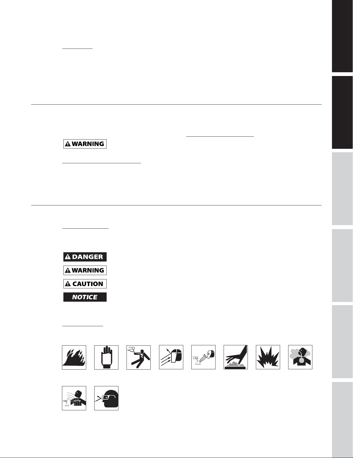
Safety Symbols
The following Safety Symbols appear throughout this manual to alert you to important safety hazards and
precautions.
Fire
or serious injury.
death or serious injury.
moderate injury.
Notice indicates important information, that if not followed, may cause damage to equipment.
MANUAL
Read
Manual
First
Risk of ShockRisk of
Risk of
Flying
Fragments
Risk of
Light Rays
Risk of
Hot Parts
Risk of
Explosion
Risk of
Fumes
TROUBLESHOOTINGOPERATION
MAINTENANCE /
REPAIR
Risk of
Magnetism
Wear eye
protection
1
Page 4
GENERAL SAFETY INSTRUCTIONS (CONTINUED)
California Proposition 65
This product can expose you to chemicals including lead, which are known to the State of
GETTING STARTED
go to www.P65Warnings.ca.gov.
This product, when used for welding, produces fumes or gases which contain chemicals known
cancer (California Health & Safety Code Section 25249.5 et seq.).
You can create dust when you cut, sand, drill or grind materials such as wood, paint, metal,
birth defects, or other reproductive harm. Wear protective gear.
California to cause cancer and birth defects or other reproductive harm. For more information
to the State of California to cause birth defects (or other reproductive harm) and, in some cases,
concrete, cement, or other masonry. This dust often contains chemicals known to cause cancer,
SAFETY /
ASSEMBLY /
SPECIFICATIONS
INSTALLATION
TROUBLESHOOTING OPERATION
REPAIR
MANUAL
Illinois Lead Poisoning Prevention Act
CONTAINS LEAD. MAY BE HARMFUL IF EATEN OR CHEWED. COMPLIES WITH
FEDERAL STANDARDS.
Circuit Requirements
This equipment requires a dedicated 120 volts. Refer to the following chart for correct circuit
circuit while operating this equipment. Extension cords are not recommended. Blown fuses and tripped circuit breakers
can result from failure to comply with this recommendation.
breaker or fuse rating for 120 volt models. Do not run other appliances, lights or tools on this
Important Safety Information
Please read and save these instructions. Read carefully before attempting to assemble, install, operate or maintain the
product described. Protect yourself and others by observing all safety information. Failure to comply with instructions
could result in personal injury and/or property damage! Retain instructions for future reference.
This manual contains important safety, operational and maintenance information. If you have any
questions, please visit www.campbellhausfeld.com for customer assistance.
General Safety
Always keep a fire extinguisher accessible while performing arc welding operations.
• Before starting or servicing any electric arc welder, read and understand all instructions. Failure to
follow safety precautions or instructions can cause equipment damage and/or serious personal injury or
death.
• All installation, maintenance, repair, and operation of this equipment should be performed by qualified
persons only in accordance with national, state, and local codes.
Improper use of electric arc welders can cause electric shock, injury, and death! Take all
• Verify all components of the arc welder are clean and in good condition prior to operating welder. Be
sure insulation on all cables, torch and power cord is not damaged. Always repair or replace damaged
components before operating the welder. Always keep welder panels, shields, etc. in place when
operating welder.
• Always wear dry, protective clothing, welding gloves and insulated footwear when operating unit.
• Always operate welder in a clean, dry, well ventilated area. Do not operate welder in humid, wet, rainy
or poorly ventilated areas.
• Be sure work piece is properly supported and grounded prior to beginning any electric arc welding
operation.
• Spread out coiled welding cable before use to avoid overheating and damage to insulation.
Never immerse wire or torch in water. If welder becomes wet for any reason, be absolutely
• Always shut equipment off and unplug power cord prior to moving the unit.
• Always attach the work lead first.
• Verify work piece is securely grounded.
• Always shut off electric arc welding equipment when not in use and cut off any excess wire from torch.
precautions described in this manual to reduce the possibility of electric shock.
certain it is completely clean and dry before use!
MAINTENANCE /
2
Page 5
• Never allow any part of the body to touch welding wire and ground or grounded work piece at the
same time.
• Awkward welding conditions and positions can be electrically hazardous. When crouching, kneeling or
at elevations, be sure to insulate all conductive parts, wear appropriate protective clothing and take
precautions to prevent injury from falls.
• Never attempt to use this equipment at current settings or duty cycles higher than specified on
equipment labels.
• Never use an electric arc welder to thaw frozen pipes.
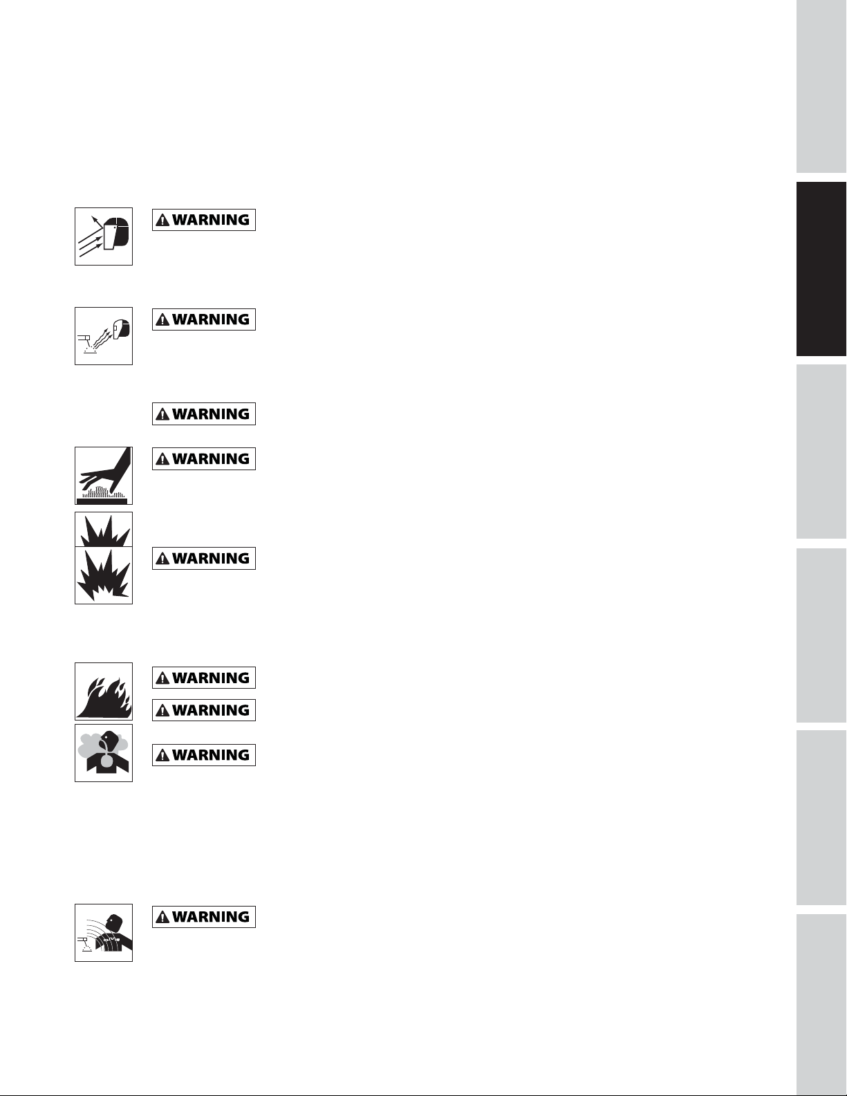
Flying sparks and hot metal can cause injury. As welds cool, slag can be thrown off. Take all
precautions described in this manual to reduce the possibility of injury from flying sparks and
hot metal.
• Wear ANSI approved face shield or safety glasses with side shield protection when chipping or grinding
metal parts.
• Wear ear plugs when welding overhead to prevent spatter or slag from falling into ears.
Electric arc welding operations produce intense light and heat and ultraviolet (UV) rays. This
intense light and UV rays can cause injury to eyes and skin. Take all precautions described in this
manual to reduce the possibility of injury to eyes and skin.
• All persons operating this equipment or in the area while equipment is in use, must wear protective
welding gear including: welding helmet or shield with at least shade 10 lens, flame resistant clothing,
leather welding gloves and full foot protection.
Never look at arc welding operations without eye protection as described above. Never use a
shade filter lens that is cracked, broken, or rated below number 10. Warn others in the area not
to look at the arc.
Electric arc welding operations cause sparks and heat metal to temperatures that can cause
severe burns! Use protective gloves and clothing when performing any metal working
operation. Take all precautions described in this manual to reduce the possibility of skin and clothing burns.
• Make sure all persons in welding area are protected from heat, sparks and ultraviolet rays. Use
additional face shields and flame resistant barriers as needed.
• Never touch work pieces until completely cooled.
Heat and sparks produced during electric arc welding and other metal working operations can
ignite flammable and explosive materials! Take all precautions described in this manual to
reduce the possibility of flames and explosions.
• Remove all flammable materials within 35 feet (10.7 meters) of welding arc. If removal is not possible,
tightly cover flammable materials with fire proof covers.
• Do not operate any electric arc welder in areas where flammable or explosive vapors may be present.
• Take precautions to ensure flying sparks and heat do not cause flames in hidden areas, cracks, etc.
Fire hazard! Do not weld on containers or pipes that contain or have contained flammable
materials or gaseous or liquid combustibles.
Arc welding closed cylinders or containers such as tanks or drums can cause explosion if not
properly vented! Verify that any cylinder or container to be welded has an adequate ventilation
hole, so that expanding gases can be released.
Do not breathe fumes produced by arc welding operation. These fumes are dangerous. If
welding area cannot be adequately ventilated, be sure to use an air-supplied respirator.
• Keep head and face out of welding fumes.
• Extremely toxic fumes are created when galvanized or cadmium plated metals or metals which contain
zinc, mercury or beryllium are heated. Complete the following precautions before performing electric
arc welding operations on these metals:
a. Remove coating from base metal.
b. Make sure welding area is well ventilated.
c. Use an air-supplied respirator.
The electromagnetic field generated during arc welding may interfere with the operation of
various electrical and electronic devices such as cardiac pacemakers. Persons using such devices
should consult with their physician prior to performing any electric arc welding operations.
• Route torch and work cables together and secure with tape when possible.
• Never wrap arc welder cables around the body.
• Always position torch and work leads on the same side of the body.
GETTING STARTED
SPECIFICATIONS
SAFETY /
INSTALLATION
ASSEMBLY /
TROUBLESHOOTINGOPERATION
MAINTENANCE /
REPAIR
3
Page 6
SAFETY /
ASSEMBLY /
GENERAL SAFETY INSTRUCTIONS (CONTINUED)
• Exposure to electromagnetic fields during welding may have other health effects which are not known.
GETTING STARTED
SPECIFICATIONS
INSTALLATION
Always be sure welding area is secure and free of hazards (sparks, flames, glowing metal or
are loosely coiled and out of the way. Be sure all metal and slag has cooled.
Cylinders can explode if damaged. Shielding gas cylinders contain gas under high pressure. If
be sure to treat them carefully.
• Protect compressed gas cylinders from excessive heat, mechanical shocks and arcs.
• Install and secure cylinders in an upright position by chaining them to stationary support or equipment
cylinder rack to prevent falling or tipping.
• Keep cylinders away from any welding or other electrical circuits.
• Never allow a welding electrode to touch any cylinder.
• Use only correct shielding gas cylinders, regulators, hoses and fittings designed for the specific
application; maintain all parts properly.
• Turn face away from valve outlet when opening cylinder valve.
• Keep protective cap in place over valve except when cylinder is in use or connected for use.
• Read and follow instructions on compressed gas cylinders, associated equipment, and CGA publication
P-1 listed in Safety Standards.
Never use flammable gasses with MIG welders. Only inert or non-flammable gasses such as c
welding.
Additional Safety Standards
ANSI Standard Z49.1 from American Welding Society, 550 N.W. Le June Rd. Miami, FL 33126
Safety and Health Standards
OSHA 29 CFR 1910, from Superintendent of Documents, U.S. Government Printing Office, Washington, D.C.
20402
National Electrical Code
NFPA Standard 70, from National Fire Protection Association, Batterymarch Park, Quincy, MA 02269
Code for Safety in Welding and Cutting
CSA Standard W117.2, from Canadian Standards Association, Standards Sales, 178 Rexdale Boulevard,
Rexdale, Ontario, Canada M9W 1R3
Cutting And Welding Processes
NFPA Standard 51B, from National Fire Protection Association, Batterymarch Park, Quincy, MA 02269
Safe Practices For Occupational And Educational Eye And Face Protection
ANSI Standard Z87.1, from American National Standards Institute, 1430 Broadway, New York, NY 10018
Refer to Material Safety Data Sheets and manufacturers instructions for metals, wire, coatings and cleaners.
slag) prior to leaving. Be sure equipment is turned off and excess wire is cut off. Be sure cables
damaged, a cylinder can explode. Since gas cylinders are normally part of the welding process,
arbon dioxide, argon, helium or mixtures of one or more of these gasses are suitable for MIG
Never lift cylinders off the ground by their valves or caps or with chains or slings.
MAINTENANCE /
TROUBLESHOOTING OPERATION
REPAIR
The DANGER, WARNING, CAUTION, and NOTICE notifications and instructions in this manual cannot
cover all possible conditions and situations that may occur. It must be understood by the operator that
caution is a factor which cannot be built into this product, but must be supplied by the operator.
SAVE THESE INSTRUCTIONS
DO NOT DISCARD
4
Page 7

SPECIFICATIONS
DW3130
Rated Input Voltage 120V
Frequency 60Hz
Phase Single
Max. Input Current 20.5A
Max. No-load Voltage 37V
Output current/voltage
@ Duty Cycle*
Usable Wire/Electrode 0.8mm or 0.9mm flux core wire
Insulation Grade H
Net Weight 44.8 lbs
80A/18V @ 20% duty cycle
45A/16.25V @ 60% duty cycle
30A/15.5V @ 100% duty cycle
0.6mm/0.8mm/0.9mm solid steel wire
DIMENSIONS
GETTING STARTED
SPECIFICATIONS
SAFETY /
DW3130
Length 20.5 inch
Width 11 inch
Height 13.1 inch
INSTALLATION
ASSEMBLY /
TROUBLESHOOTINGOPERATION
MAINTENANCE /
REPAIR
5
Page 8

SAFETY /
ASSEMBLY /
GLOSSARY OF WELDING TERMS
AC or Alternating Current - electric current that reverses direction periodically. Sixty cycle current travels in both
directions sixty times per second.
Arc Length - the distance from the end of the electrode to the point where the arc makes contact with the work surface.
Base Metal - the material to be welded.
GETTING STARTED
Butt Joint - a joint between two members aligned approximately in the same plane.
Crater - a pool, or pocket, that is formed as the arc comes in contact with the base metal.
DC or Direct Current - electric current which flows only in one direction. The polarity (+ or -) determines which direction
the current is flowing.
DC Reverse Polarity - occurs when the electrode holder is connected to the positive pole of the welding machine. Reverse
Polarity directs more heat into melting the electrode rather than the work piece. It is used on thinner material.
DC Straight Polarity - occurs when the electrode holder is connected to the negative pole of the welding machine. With
straight polarity more heat is directed to the work piece for better penetration on thicker material.
SPECIFICATIONS
Electrode - a coated metal wire having approximately the same composition as the material being welded.
Fillet Weld - approximately a triangle in cross-section, joining two surfaces at right angles to each other in a lap, T or
corner joint.
Flux - a coating, when heated, that produces a shielding gas around the welding area. This gas protects the parent and
filler metals from impurities in the air.
Flux Cored Arc Welding (FCAW) - also called Gasless, is a welding process used with a wire-feed welding machine. The
weld wire is tubular with flux material contained inside for shielding.
Gas Metal Arc Welding (GMAW) - also called MIG, is a welding process used with a wire feed welding machine. The wire
is solid and an inert gas is used for shielding.
Gas Tungsten Arc Welding (GTAW) - also called TIG, is a welding process used with welding equipment with a high
INSTALLATION
frequency generator. The arc is created between a non-consumable tungsten electrode and the work piece. Filler metal
may or may not be used.
Lap Joint - a joint between two overlapping members in parallel planes.
Open Circuit Voltage (OCV) - the voltage between the electrode and the work clamp of the welding machine when no
current is flowing (not welding). The OCV determines how quickly the arc is struck.
Overlap - occurs when the amperage is set too low. In this instance, the molten metal falls from the electrode without
actually fusing into the base metal.
Porosity - gas pockets, or cavities, formed during weld solidification. They weaken the weld.
Penetration - the depth into the work piece that has been heat effected by the arc during the welding process. A good
weld achieves 100% penetration meaning that the entire thickness of the work piece has been heated and resolidified.
The heat effected area should be easily seen on the opposite side of the weld.
Shielded Metal Arc Welding (SMAW) - also called Stick, is a welding process with uses a consumable electrode to support
the arc. Shielding is achieved by the melting of the flux coating on the electrode.
Slag - a layer of flux soot that protects the weld from oxides and other contaminants while the weld is solidifying
(cooling). Slag should be removed after weld has cooled.
Spatter - metal particles thrown from the weld which cool and harden on the work surface. Spatter can be minimized by
using a spatter resistant spray on the work piece before welding.
Tack Weld - weld made to hold parts in proper alignment until final welds are made.
Travel Angle - the angle of the electrode in the line of welding. It varies from 5º to 45º depending on welding conditions.
T Joint - made by placing the edge of one piece of metal on the surface of the other piece at approximately a 90º angle.
Undercut - a condition that results when welding amperage is too high. The excessive amperage leaves a groove in the
TROUBLESHOOTING OPERATION
base metal along both sides of the bead which reduces the strength of the weld.
Weld Pool or Puddle - a volume of molten metal in a weld prior to its solidification as weld metal.
Weld Bead - a narrow layer or layers of metal deposited on the base metal as the electrode melts. Weld bead width is
typically twice the diameter of the electrode.
Work Angle - the angle of the electrode from horizontal, measured at right angles to the line of welding.
REPAIR
MAINTENANCE /
6
Page 9
GETTING TO KNOW YOUR UNIT
GETTING STARTED
4
1
SPECIFICATIONS
5
6
3
SAFETY /
INSTALLATION
ASSEMBLY /
2
Figure 1 - Model DW3130
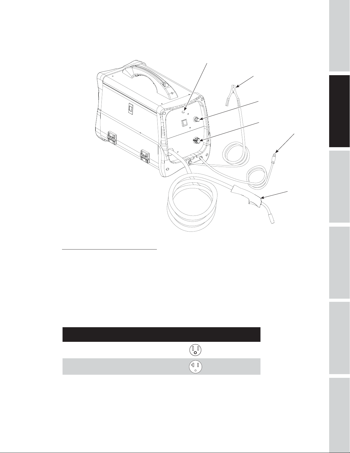
Components and Controls (Figure 1)
1. Work Clamp – connects to work piece.
2. Torch with .030 inch tip.
3. Power Cord – plug into 120 volt outlet.
4. Light – illuminates if thermostat has automatically shut welder off.
5. Infinite Wire Speed Control – turn clockwise to increase wire speed and counterclockwise to decrease
wire speed.
6. Off/Heat Selector - Selects welding power and turns welder on.
Four selections are possible: 1 – 2 – 3 – 4.
HEAT SELECTOR
1-2-3 15 amp
CIRCUIT BREAKER OR SLOW BLOW FUSE FOR
120V MODELS
TROUBLESHOOTINGOPERATION
4 20 amp
See page 17 for supply cable replacement instructions.
7
MAINTENANCE /
REPAIR
Page 10
SAFETY /
ASSEMBLY /
INSTALLATION INSTRUCTIONS
Location
Selecting the proper location can significantly increase performance, reliability and life of the arc welder.
GETTING STARTED
SPECIFICATIONS
• For best results locate welder in a clean and dry environment. Dust and dirt in the welder retain
moisture and increase wear of moving parts.
• Place welder in an area with at least twelve inches (30,48 cm) of ventilation space at both the front and
rear of unit. Keep all obstructions out of this ventilation space.
• Store welding wire in a clean, dry location with low humidity to prevent oxidation.
• Use a properly grounded receptacle for the welder and ensure welder is the only load on power supply
circuit. Refer to chart on page 7 for correct circuit capacity.
• Use of an extension cord is not recommended for electric arc welding machines. Voltage drop in the
extension cord may significantly degrade performance of the welder.
ASSEMBLY INSTRUCTIONS
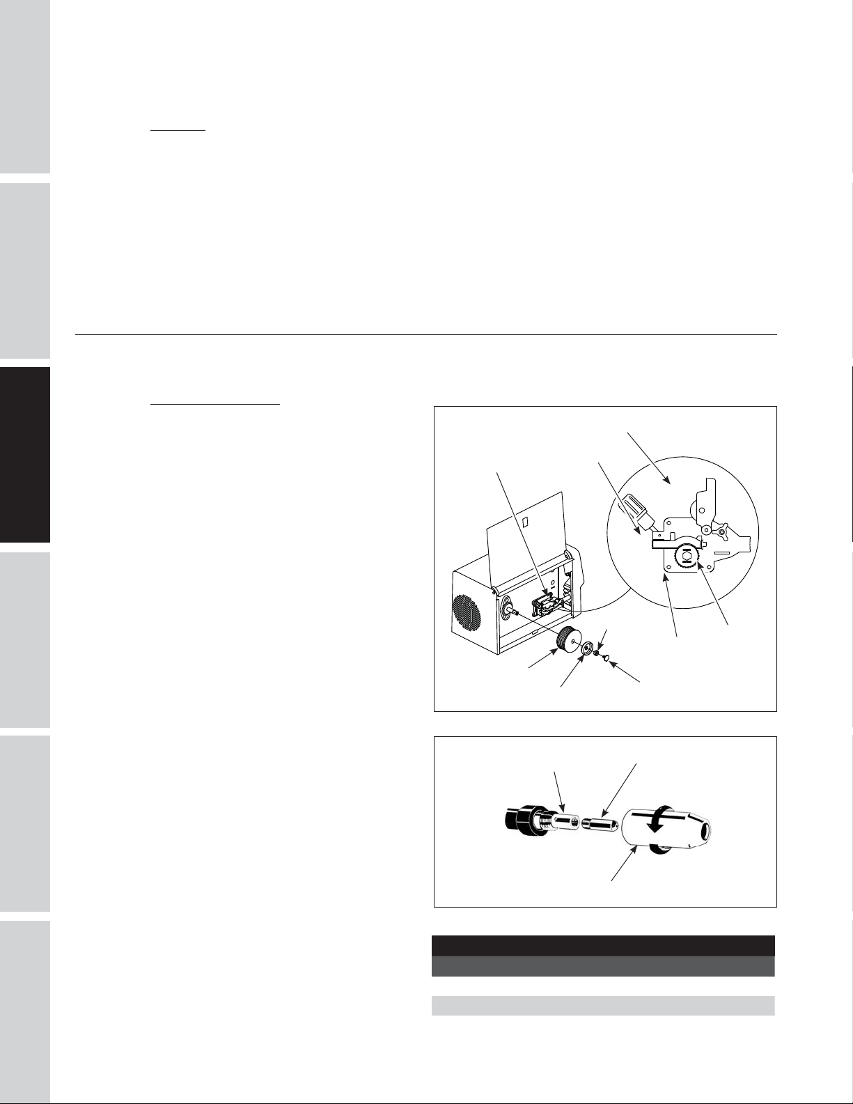
WIRE INSTALLATION
NOTE: Before installing welding wire, be sure:
a. Diameter of welding wire matches
groove in drive roller on wire feed
mechanism (See Figure 2).
INSTALLATION
TROUBLESHOOTING OPERATION
REPAIR
b. Wire matches contact tip in end of
torch (See Figure 3).
A mismatch on any item could cause the wire
to slip and/or bind.
NOTE: Always maintain control of loose end
of welding wire to prevent unspooling.
1. Verify unit is off and open door panel to
expose wire feed mechanism.
2. Remove the spool lock by pushing in and
rotating 1/4 turn counterclockwise. Then
remove lock, spring and retainer.
3. Flip tensioning knob down and swing
arm up on drive mechanism. This allows
initial feeding of wire into torch liner by
hand.
4. Install wire spool onto spindle so wire
can come off bottom of spool. Do not cut
the wire loose yet. Install retainer, spring
and lock by pushing in and turning lock
1/4 rotation clockwise.
5. Hold wire and cut the wire end from
spool. Do not allow wire to unravel. Be
sure end of wire is straight and free of
burrs.
6. Feed wire through wire guide, over the
groove in drive roller and into torch wire
liner. Flip swing arm down and tension
knob up. Adjust tension by rotating
tension knob.
7. Unscrew nozzle and contact tip from
end of welding torch (See Figure 3).
Plug welder into a proper power supply
receptacle.
Swing arm
Drive deck
Welding wire
Figure 2 - Weld wire installation
Torch Diffuser
Figure 3 - Torch needle
Wire guide
Retainer
CONTACT TIP MARKINGS
Mark Wire Size
0.6 mm .024 inch
0.8 mm .030 inch
0.9 mm .035 inch
Spring
Nozzle
Tension knob
Lock
Contact Tip
Drive
roller
MAINTENANCE /
8
Page 11
8. Turn on welder and set wire speed to 10. Activate torch trigger until wire feeds out past the torch end.
Turn welder off.
9. Carefully slip contact tip over wire, screw tip into torch end and reinstall nozzle (See Figure 3). Cut wire
off approximately 1/4 inch from nozzle end.
Duty Cycle / Thermostatic Protection
Welder duty cycle is the percentage of actual weld time that can occur in a ten minute interval. For
example, at a 20% duty cycle, actual welding can occur for two minutes, then the welder must cool for
eight minutes.
Internal components of this welder are protected from overheating with an automatic thermal switch. An
amber lamp is illuminated on the front panel if the duty cycle is exceeded. Do not switch unit off. This will
allow the internal fan to cool the unit quickly. Welding operations may continue when the amber lamp is
no longer illuminated.
Polarity
MIG welding wire requires the electrode to be positive.
Flux welding wire requires the electrode to be negative. Always use the polarity recommended by the
welding wire manufacturer. The welder is factory set for flux welding wire.
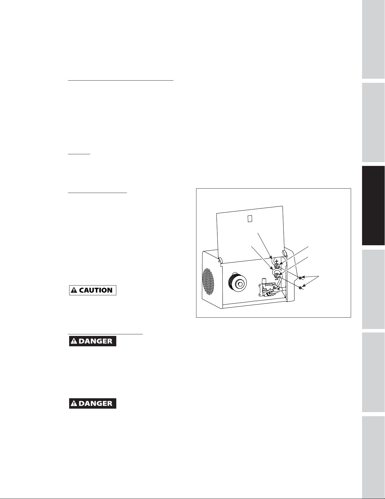
TO CHANGE POLARITY (SEE FIGURE 4)
1. Unplug power cord from socket.
2. Open wire feed compartment door.
3. Remove two nuts from polarity studs.
4. Connect cable from drive deck to positive
stud and cable from work clamp to
negative stud for electrode positive
polarity for MIG welding. Connect cable
from drive deck to negative stud and
cable from work clamp to positive stud
Ground cable
Drive deck
cable
NOTE: Electrode negative
polarity (typical for flux
core welding) shown in
figure.
Reverse cables for
electrode positive polarity
(typical for MIG welding).
Positive stud
Negative stud
for electrode negative polarity for flux
core welding.
Brass nuts
5. Reinstall two nuts and tighten securely.
If the nuts are not
excessive heat will be generated by the loose
connection and the insulators on the studs will be
damaged.
tightened properly,
Figure 4 - Polarity control
Shielding Gas Preparation
Improper handling and maintenance of compressed gas cylinders and regulators can result in
cylinder from falling over. Read, understand and follow all compressed gas and equipment warnings in the safety
instructions.
NOTE: Shielding gas is not required if flux-core welding wire is used.
serious injury or death! Always secure gas cylinders to a wall or other fixed support to prevent
GETTING STARTED
SPECIFICATIONS
SAFETY /
INSTALLATION
ASSEMBLY /
TROUBLESHOOTINGOPERATION
GAS TYPES
There are 3 types of gas generally used for gas metal arc welding; 100% argon, a mixture of 75% argon and
25% carbon dioxide (C25) or 100% carbon dioxide.
Use ONLY the type of gas recommended for your welder. Use ONLY an inert, non-flammable
type of gas. Failure to do so will result in a very hazardous situation.
The 75/25 mixture is recommended for general steel welding. For aluminum welding, use 100% argon.
Cylinders of either type gas may be obtained at your local welding supply outlet. Secure cylinder to prevent
it from falling over.
9
MAINTENANCE /
REPAIR
Page 12
ASSEMBLY INSTRUCTIONS (CONTINUED)
Obtaining Correct Gas Type. The gas used in any welding application for your welder must be an INERT,
NON-FLAMMABLE TYPE. You can get the type of gas needed from a nearby welding gas distributor (often
found in the yellow pages under “Welders” or “Welding Equipment”).
SAFETY /
ASSEMBLY /
GETTING STARTED
REGULATOR
The regulator provides a constant shielding gas pressure and flow rate during the welding process. Each
regulator is designed to be used with a specific gas or mixture of gases. The argon and argon mixture use
the same thread type. The 100% carbon dioxide uses a different thread type. An adapter is available at your
local welding gas supplier to change between the two.
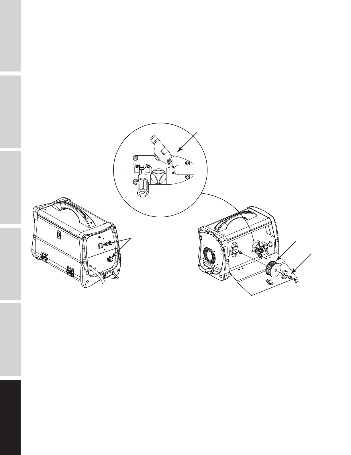
HOSE AND REGULATOR HOOKUP PROCEDURE
Cylinder gas is under high pressure. Point cylinder outlet away from yourself and any
SPECIFICATIONS
1. With cylinder securely supported, stand on side of cylinder opposite cylinder outlet then remove
cylinder cap and open valve slightly by turning counterclockwise. When gas is emitted from cylinder,
close valve by turning clockwise. This will blow out dust or dirt that may have accumulated around
valve seat.
2. Install regulator onto cylinder valve. Tighten stem nut securely to gas valve.
3. Install one end of gas hose to fitting on the back of welder and other end of hose to fitting on
regulator. Make sure gas hose is not kinked or twisted.
4. While standing opposite cylinder outlet, slowly open cylinder valve. Inspect for leaks in the connections.
5. Remember to close gas cylinder valve when finished welding.
INSTALLATION
OPERATING INSTRUCTIONS
1. Be sure to read, understand and comply with all precautions in the General Safety Instructions section.
MANUAL
Be sure to read entire “Welding Guidelines” section before using this equipment.
2. Turn welder off.
3. Verify surfaces of metals to be joined are free from dirt, rust, paint, oil, scale or other contaminants.
These contaminants make welding difficult and cause poor welds.
All persons operating this equipment or in the area while equipment is in use must wear
clothing, leather welding gloves and full foot protection.
If heating, welding or cutting galvanized, zinc plated, lead, or cadmium plated materials, refer
when these metals are heated.
4. Connect work clamp to work piece or workbench (if metal). Make sure contact is secure. Avoid surfaces
with paint, varnish, corrosion or non-metallic materials.
5. Rotate Wire Speed Control to setting per decal inside wire feed compartment, then adjust as needed
after test.
6. Plug power cord into a proper voltage receptacle with proper circuit capacity (see circuit requirements
on Page 6).
7. Switch welder on to desired heat setting per decal inside wire feed compartment, then adjust as
needed after test.
NOTE: These settings are general guidelines only. Heat setting may vary according to welding conditions
and materials.
TROUBLESHOOTING OPERATION
8. Verify wire is extended 1/4 inch from contact tip. If not, squeeze trigger to feed additional wire, release
trigger, turn welder off, and cut wire to proper length. Then, switch back on to desired heat setting.
9. Position torch near work piece, lower welding helmet by nodding head or positioning the hand shield,
and squeeze torch trigger. Adjust heat setting and wire speed as needed.
10. When finished welding, turn welder off and store properly.
bystanders before opening.
protective welding gear including: eye protection with proper shade 10, flame resistant
to the General Safety Instructions Section for instructions. Extremely toxic fumes are created
REPAIR
MAINTENANCE /
10
Page 13
WELDING GUIDELINES
General
The DW3130 can utilize the Flux Cored Arc
Welding (FCAW) process or the Gas Metal Arc
Welding (GMAW) process. The weld must be
protected (shielded) from contaminants in
the air while it is molten. The FCAW process
uses a tubular wire with a flux material
inside. The flux creates a shielding gas when
melted. The GMAW process uses inert gas to
shield the weld while molten.
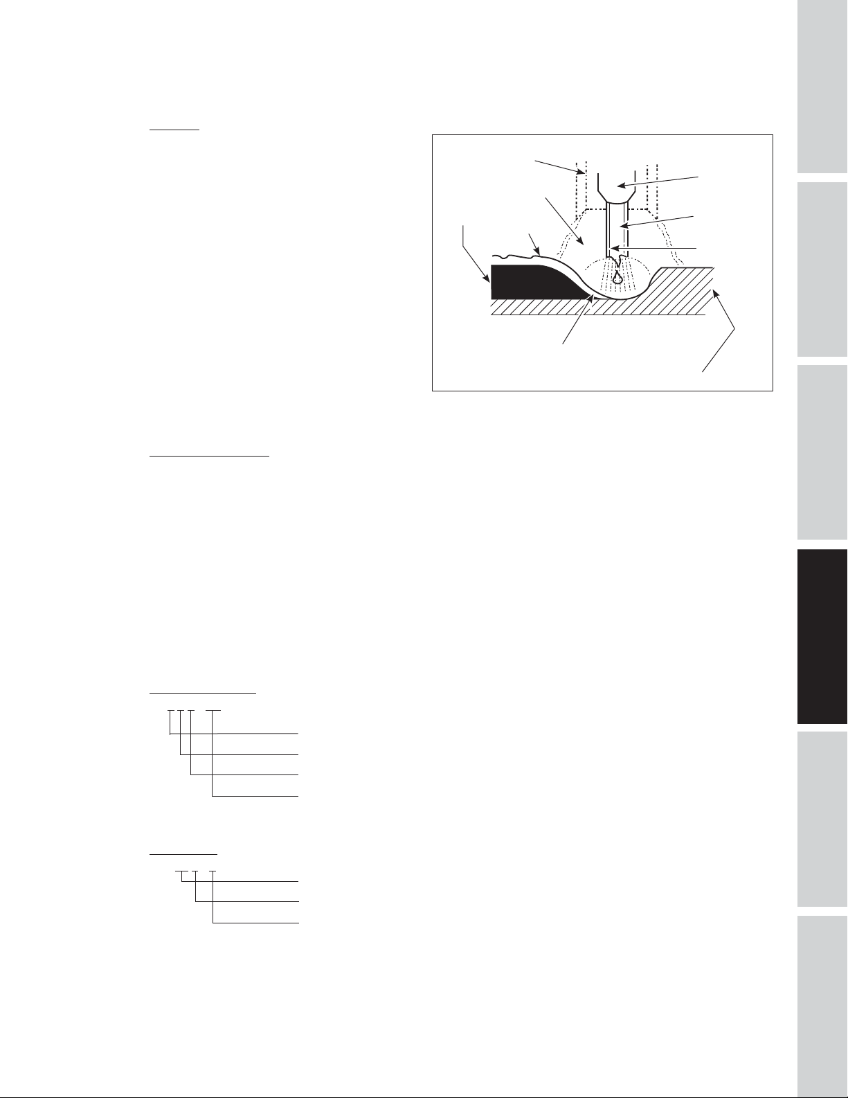
When current is produced by a transformer
(welding machine) and flows through the
circuit to the weld wire, an arc is formed
between the end of the weld wire and the
work piece. This arc melts the wire and the
work piece. The melted metal of the weld
wire flows into the molten crater and forms
a bond with the work piece as shown (Figure
5).
Nozzle
Shielding Gas
Weld
Figure 5 - Weld Components
Slag
Crater
Work piece
Contact Tip
Flux
(Gasless only)
Wire
GETTING STARTED
SPECIFICATIONS
SAFETY /
INSTALLATION
ASSEMBLY /
Arc Welding Basics
Six basic techniques affect weld quality. These are: wire selection, heat setting, weld angle, wire speed,
travel speed, and electrode extension. An understanding of these techniques is necessary for effective
welds.
HEAT SETTING
The correct heat involves the adjustment of the welding machine to the required setting. Heat or voltage is
regulated by a switch on the welder. The heat setting used depends on the size (diameter) and type of wire,
position of the weld, and the thickness of the work piece. Consult specifications listed on the welder. It is
suggested that the welder practice with scrap metal to adjust settings, and compare welds with Figure 7.
WIRE TYPE AND SIZE
The correct choice of wire type involves a variety of factors, such as welding position, work piece material
type, thickness, and condition of surface to be welded. The American Welding Society, AWS, has set up
certain requirements for each type of wire.
FLUX-CORED WIRE
E - 7 0 T - GS
Weld strength, times 10,000 pounds per square inch
Welding positions (0 for flat or horizontal, 1 for any position)
Tubular flux-cored wire
Flux type
AWS E71T-GS or E71T-11 is recommended for this welder.
SOLID WIRE
ER - 70 S - 6
Weld strength, times 1,000 PSI
Solid wire
Wire composition
TROUBLESHOOTINGOPERATION
MAINTENANCE /
REPAIR
ER-70S6 is recommended for this welder.
11
Page 14
SAFETY /
WELDING GUIDELINES (CONTINUED)
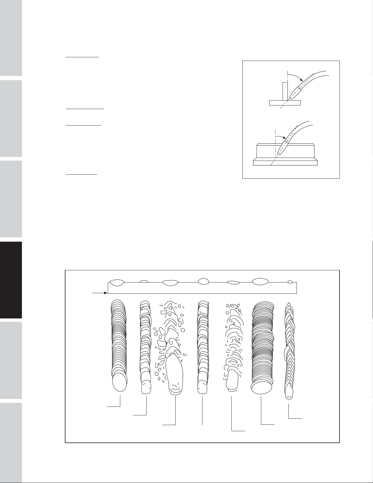
Weld Angle
Weld angle is the angle at which the nozzle is held during
GETTING STARTED
SPECIFICATIONS
the welding process. Using the correct angle ensures proper
penetration and bead formation. As different welding positions
and weld joints become necessary, nozzle angle becomes an
increasingly important factor in obtaining a satisfactory weld.
Weld angle involves two positions - travel angle and work angle.
TRAVEL ANGLE is the angle in the line of welding and may vary
from 5º to 45º from the vertical, depending on welding conditions.
WORK ANGLE is the angle from horizontal, measured at right
angles to the line of welding.
For most applications, a 45º travel angle and 45º work angle
is sufficient. For specific applications, consult an arc welding
handbook.
5° - 45°
Work Angle
5° - 45°
ASSEMBLY /
INSTALLATION
Wire speed
The wire speed is controlled by the knob on the front panel. The
Figure 6 - Weld Angle
Travel Angle
speed needs to be “tuned” to the rate at which the wire is being
melted in the arc. Tuning is one of the most critical functions of
wire feed welding. Tuning should be performed on a scrap piece of metal the same type and thickness as
that to be welded. Begin welding with one hand “dragging” the torch nozzle across the scrap piece while
adjusting the wire speed with the other hand. Too slow of speed will cause sputtering and the wire will
burn up into the contact tip. Too fast a speed will also cause a sputtering sound and the wire will push into
the plate before melting. A smooth buzzing sound indicates the wire speed is properly tuned. Repeat the
tuning procedure each time there is a change in heat setting, wire diameter or type, or work piece material
type or thickness. For Aluminum, wire speed is typically set higher (7-9 speed range).
Base
Metal
MAINTENANCE /
TROUBLESHOOTING OPERATION
REPAIR
Normal Heat,
Wire Speed,
Travel Speed
Heat Too Low
Figure 7 - Weld Appearance
Heat Too High
Wire Speed
Too Fast
12
Travel Speed
Too Fast
Travel Speed Too Slow
Wire Speed Too
Slow
Page 15
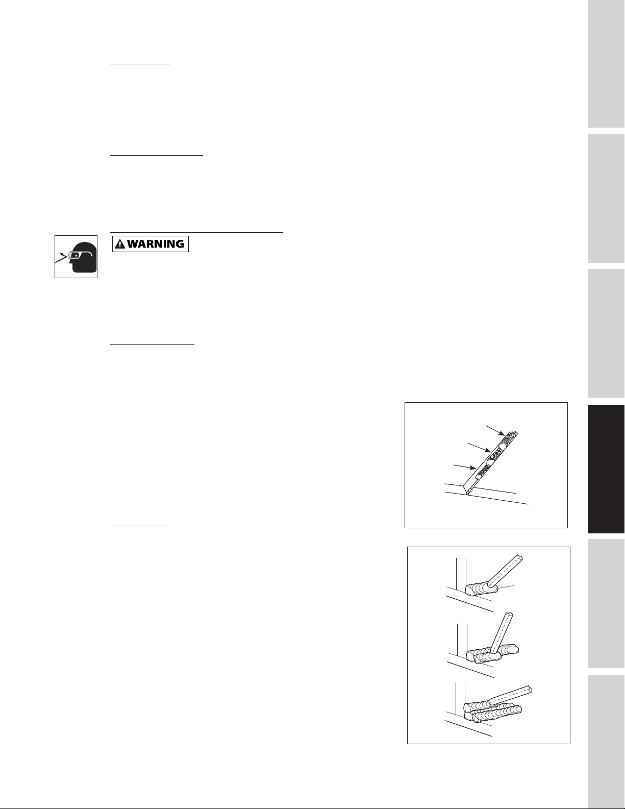
Travel Speed
The travel speed is the rate at which the torch is moved across the weld area. Factors such as diameter and
type of weld wire, amperage, position, and work piece material thickness all affect the speed of travel
necessary for completing a good weld (See Figure 7). When the speed is too fast, the bead is narrow and
bead ripples are pointed as shown. When the speed is too slow, the weld metal piles up and the bead is
high and wide. For Aluminum, travel speed is typically faster.
Electrode Extension
Electrode extension (or electrode stick-out) is the distance between the end of the contact tip and and the
end of the welding wire. The recommended electrode extension is from 1/4 to 1/2 in (6 to 13 mm). If the
electrode extension is too long, welding current will be reduced and the bead will be high and narrow with
less penetration.
Slag Removal (Flux-Cored Wire Only)
Wear ANSI approved safety glasses (ANSI Standard Z87.1) and protective clothing when
removing slag. Hot, flying debris can cause personal injury to anyone in the area.
After completing the weld, wait for the welded sections to cool. A protective coating called slag now covers
the weld bead which prevents contaminants in the air from reacting with the molten metal. Once the
weld cools to the point that it is no longer glowing red, the slag can be removed. Removal is done with a
chipping hammer. Lightly tap the slag with the hammer and break it loose from the weld bead. The final
clean-up is done with a wire brush. When making multiple weld passes, remove the slag before each pass.
GETTING STARTED
GETTING STARTED
SPECIFICATIONS
SPECIFICATIONS
SAFETY /
SAFETY /
INSTALLATION
INSTALLATION
ASSEMBLY /
ASSEMBLY /
Welding Positions
Four basic welding positions can be used; flat, horizontal, vertical, and overhead. Welding in the flat
position is easier than any of the others because welding speed can be increased, the molten metal has less
tendency to run, better penetration can be achieved, and the work is less fatiguing. Welding is performed
with the wire at a 45º travel angle and 45º work angle.
Other positions require different techniques such as a weaving
pass, circular pass, and jogging. A higher skill level is required to
complete these welds.
Overhead welding is the least desirable position as it is the most
Cover
Filler
difficult and dangerous. Heat setting and wire selection will vary
depending upon the position.
Root
All work should be performed in the flat position if possible. For
specific applications, consult an arc welding technical manual.
Weld Passes
Sometimes more than one pass is necessary to fill the joint. The
root pass is first, followed by filler passes and the cover pass. If the
pieces are thick, it may be necessary to bevel the edges that are
joined at a 60º angle. Remember to remove the slag before each
pass for the FCAW process.
Figure 8 - Weld Passes
TROUBLESHOOTINGOPERATION
TROUBLESHOOTINGOPERATION
13
13
Figure 9 - Multiple Weld Passes
MAINTENANCE /
REPAIR
MAINTENANCE /
REPAIR
Page 16
SAFETY /
ASSEMBLY /
WELDING GUIDELINES (CONTINUED)
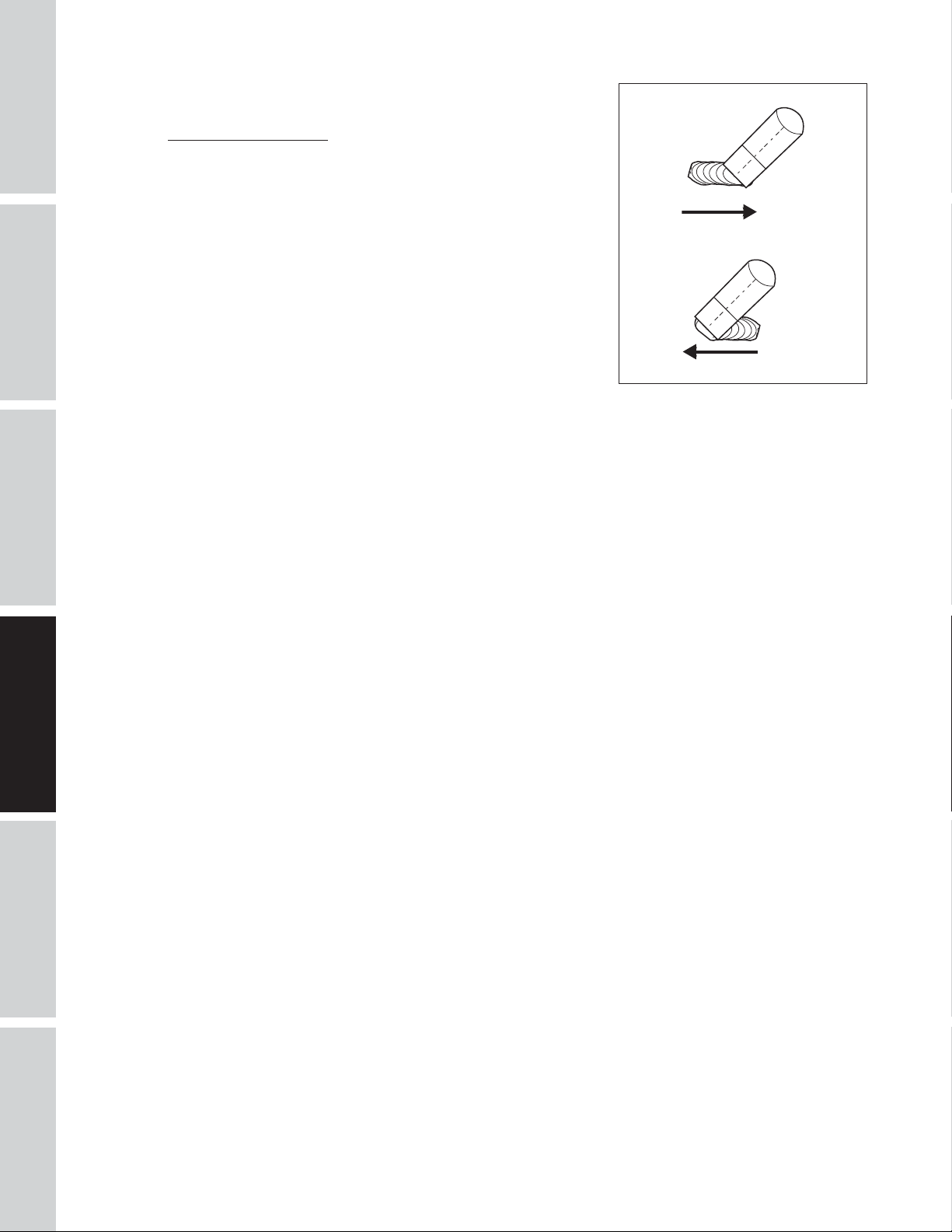
Push vs Pull Technique
The type and thickness of the work piece dictates which way to
GETTING STARTED
SPECIFICATIONS
INSTALLATION
point the torch nozzle. For thin materials (18 gauge and smaller)
and all aluminum, the nozzle should point out in front of the weld
puddle and push the puddle across the workpiece. For thicker
steel, the nozzle should point into the puddle to increase weld
penetration. This is called backhand or pull technique (See Figure
10).
PULL
PUSH
Figure 10
MAINTENANCE /
TROUBLESHOOTING OPERATION
REPAIR
14
Page 17

NOTES
GETTING STARTED
SPECIFICATIONS
SAFETY /
INSTALLATION
ASSEMBLY /
15
TROUBLESHOOTINGOPERATION
MAINTENANCE /
REPAIR
Page 18

SAFETY /
ASSEMBLY /
TROUBLESHOOTING GUIDE
SYMPTOM POSSIBLE CAUSE(S) CORRECTIVE ACTION
No output 1. Duty cycle exceeded 1. Allow welder to cool until lamp goes out.
GETTING STARTED
Wire tangles at drive roller 1. Wrong size contact tip 1. Use proper size contact tip.
Gun nozzle arcs to work
surface
SPECIFICATIONS
INSTALLATION
TROUBLESHOOTING OPERATION
Work clamp and/or cable gets
hot
Wire does not feed 1. Wire jammed 1. Reload wire.
(Aluminum) Wire burns back
into tip or (Aluminum) Metal
bubbles or burns through
Weld pops and sputters 1. Wire speed setting 1. Tune in correct setting (1-5 mild steel; 5-10
Bead is intermittently too thin 1. Inconsistent travel speed 1. Decrease and maintain constant travel speed.
Bead is intermittently too thick 1. Slow and/or inconsistent travel speed 1. Increase and maintain travel speed.
Ragged depressions at edge
of weld
Weld bead does not penetrate
base metal
Wire sputters and sticks 1. Damp wire 1. Use dry wire and store in dry location.
2. Poor work clamp connection 2. Be sure all connections are secure, and attaching
3. Blown breaker or fuse 3. Reduce circuit load, reset breaker or replace fuse.
2. Torch liner clogged or damaged 2. Clean or replace wire liner.
3. Contact tip clogged or damaged 3. Clean or replace contact tip.
4. Drive roller worn 4. Replace.
5. Not enough tension 5. Tighten tension knob.
1. Slag inside gun nozzle 1. Clean slag from gun nozzle.
2. Insulation ring melted/expired 2. Replace nozzle.
1. Poor contact 1. Be sure all connections are secure, and attaching
2. Using an extension cord with
excessive length
2. Out of wire 2. Replace wire spool.
3. Not enough tension 3. Tighten tension knob if wire is slipping.
4. Wire liner worn 4. Replace liner.
5. Wire disconnected internally 5. Visit www.campbellhausfeld.com
6. Contact tip clogged 6. Replace contact tip.
1. Wire speed too slow 1. Run speed in 7 - 10 range.
2. Travel speed too slow or heat is too
high
2. Contact tip size too large 2. Replace contact tip.
3. Polarity set incorrectly 3. Reverse polarity.
4. Drive roller slipping 4. Increase tension.
5. Gas bottle empty 5. Replace gas bottle.
2. Output heat setting too low 2. Increase output heat setting.
2. Output heat setting too high 2. Reduce output heat setting.
1. Travel speed too fast 1. Decrease travel speed.
2. Wire speed too fast 2. Decrease wire speed.
3. Output heat setting too high 3. Reduce output heat setting.
1. Inconsistent travel speed 1. Decrease and maintain constant travel speed.
2. Output heat setting too low 2. Increase output heat setting.
3. No or low shielding gas 3. Use gas for MIG process or refill bottle.
4. Wrong shielding gas (aluminum) 4. Use only 100% Argon gas.
5. Extension cord is too long 5. Never use an extension cord longer than 20 ft.
6. (Aluminum) Possible oxide buid-up
on surface
2. Wire speed too fast 2. Reduce wire speed.
3. Wrong type of wire 3. Use flux-cored wire when not using gas.
4. No or low shielding gas 4. Use gas for MIG process or refill bottle.
surface is clean.
surface is clean.
2. Never use an extension cord longer than 20 ft.
2. Increase the travel speed or reduce heat settings.
aluminum).
6. Clean surface thoroughly with a stainless steel brush
only.
REPAIR
MAINTENANCE /
16
Page 19
MAINTENANCE
Disconnect power supply and turn machine off before inspecting or servicing any components.
Before Every Use:
1. Check condition of weld cables and immediately repair or replace any cables with damaged insulation.
2. Check condition of power cord and immediately repair or replace any cord if damaged.
3. Inspect the condition of the torch contact tip and nozzle. Remove any weld slag. Replace torch contact
tip or nozzle if damaged.
Do not operate this welding machine with cracked or missing insulation on welding cables,
Every 3 Months:
1. Replace any unreadable safety labels on the welder.
2. Use compressed air to blow all dust and lint from ventilation openings.
3. Clean wire groove on drive roller. Remove drive roller and use a small wire brush to clean. Replace if
worn or damaged.
Keep wire compartment cover closed at all times unless wire needs to be changed.
torch or power cord.
GETTING STARTED
SPECIFICATIONS
SAFETY /
INSTALLATION
ASSEMBLY /
Consumable and Wear Parts
The following parts require replacement:
• Wire feed drive roller
• Torch liner
• Nozzle/contact tips
• Wire - This welder will accept either 4 inch or 8 inch diameter spools. Flux-Cored welding wire is
susceptible to moisture and oxidizes over time, so it is important to select a spool size that will be
used within approximately 6 months. For mild steel welding, AWS ER70S6 solid wire or AWS E71TGS Flux-Cored wire is recommended.
SUPPLY CABLE REPLACEMENT
1. Verify that welder is OFF and power cord disconnected.
2. Remove welder side panel to expose switches.
3. Disconnect the power cord leads per the diagram inside the unit.
4. Disconnect the ground wire connected to welder base.
5. Loosen the cord strain relief screws and pull cord out of strain relief.
6. Install new cord in reverse order per the diagram inside the unit.
Changing Wire Sizes
This welder is setup for .030 inch (0.8 mm) wire. If a different wire size is used, the wire feed drive roller
and contact tip may need changing. There are two grooves in the drive roller. The small groove is for .024
inch (0.6 mm) MIG wire and the large groove is for .030 inch - .035 inch (0.8 mm - 0.9 mm) flux core and MIG
wire. Rotate the tension knob down and swing arm up. Remove roller support by removing two screws and
flip the drive roller to choose the correct groove. The contact tip should also match the wire diameter used.
The tip diameter is marked on the contact tip in inches and/or millimeters.
TROUBLESHOOTINGOPERATION
MAINTENANCE /
REPAIR
17
Page 20
SAFETY /
ASSEMBLY /
REPAIR PARTS ILLUSTRATION FOR DW3130
GETTING STARTED
SPECIFICATIONS
INSTALLATION
3
2
TROUBLESHOOTING OPERATION
For Repair Parts, visit www.campbellhausfeld.com
24 hours a day – 365 days a year
Please provide following information:
- Model number
- Serial number (if any)
- Part description and number as shown in parts list
REPAIR
4
1
MAINTENANCE /
18
Page 21

REPAIR PARTS LIST FOR DW3130
Ref.
No. Description Part Number:
1 SPOOL SPINDLE KIT: INCLUDES KNOB, WASHER, SPOOL TENSIONER SPRING AND
SPOOL LOCKING KNOB
2 KNOB/SWITCH KIT: INCLUDES ON/OFF SWITCH, POWER LEVEL KNOB,
POTENTIOMETER, VOLTAGE SWITCH AND WIRE SPEED KNOB
3 WIRE FEED KIT: INCLUDES WIRE FEED UNIT, WIRE FEED ROLLER DW313013AV
4 SAMPLE SPOOL AND TIPS KIT: INCLUDES SAMPLE WIRE SPOOL (0.8MM), CONTACT
TIPS AND HEX WRENCH
5 HOSE AND CLAMP KIT: INCLUDES AIR HOSE AND CLAMPS DW313015AV
DW313011AV
DW313012AV
DW313014AV
GETTING STARTED
SPECIFICATIONS
SAFETY /
INSTALLATION
ASSEMBLY /
19
TROUBLESHOOTINGOPERATION
MAINTENANCE /
REPAIR
Page 22

Reminder: Keep your dated proof of purchase for warranty purposes! Attach it to this manual or file it for safekeeping.
LIMITED WARRANTY
1. Duration: The manufacturer warrants that it will repair, at no charge for parts or labor, the Welder, Welding Gun, or Cables,
proven defective in material or workmanship, during the following time period(s) after date of original retail purchase:
- For 5 Years: The Welder Transformer and Rectifier (as applicable)
- For 90 Days: The Welding Clamps, MIG Gun, Electrode Holder, Accessories, and Welding Cables (as applicable)
2. Who Gives This Warranty (Warrantor): Campbell Hausfeld a Marmon/Berkshire Hathaway Company, 100 Production Drive,
Harrison, Ohio, 45030. Visit: www.campbellhausfeld.com.
3. Who Receives This Warranty (Purchaser): The original purchaser of the Campbell Hausfeld product.
4. What is covered under this warranty: Defects in material and workmanship which occur within the duration of the warranty
period. This warranty extends to the Welder, the Welders Transformer and Rectifier, Welding Gun or Electrode Holder, and
cables only.
5. What is not covered under this warranty:
A. Implied warranties, including those of merchantability and FITNESS FOR A PARTICULAR PURPOSE ARE LIMITED IN
DURATION TO THIS EXPRESS WARRANTY. After this period, all risks of loss, from whatever reason, shall be on the
purchaser. Some states do not allow limitations on how long an implied warranty lasts, so above limitations may not
apply to you.
B. ANY INCIDENTAL, INDIRECT, OR CONSEQUENTIAL LOSS, DAMAGE, OR EXPENSE THAT MAY RESULT FROM ANY DEFECT
FAILURE OR MALFUNCTION OF THE CAMPBELL HAUSFELD PRODUCT. Some states do not allow limitations on how long
an implied warranty lasts, so above limitations may not apply to you.
C. This warranty does not apply to any accessory items included with the product which are subject to wear from usage; the
repair or replacement of these items shall be at the expense of the owner. These MIG items include but are not limited
to; Contact Tips, Nozzles, Gun Liners, Drive Rollers, Felt Wire Cleaner. In addition, this warranty does not extend to any
damage caused by the untimely replacement or maintenance of any of the previously listed CONSUMABLE parts.
D. Any failure that results from accident, purchaser’s abuse, neglect or failure to operate products in accordance with
instructions provided in the owner’s manual(s) supplied with the product.
E. Pre-delivery service, i.e. assembly and adjustment.
6. Responsibilities of Warrantor under this warranty: Repair or replace, at Warrantor’s option, products or components which
have failed within duration of the warranty period.
7. Responsibilities of purchaser under this warranty:
A. Visit www.campbellhausfeld.com for warranty assistance.
B. Provide dated proof of purchase and maintenance records.
C. All welders must be delivered or shipped to the nearest Campbell Hausfeld Authorized Service Center. Freight costs, if
any, must be borne by the purchaser.
D. Use reasonable care in the operation and maintenance of the products as described in the owner’s manual(s).
8. When Warrantor will perform repair or replacement under this warranty: Repair or replacement will be scheduled and
serviced according to the normal work flow at the servicing location, and depending on the availability of replacement parts.
This Limited Warranty gives you specific legal rights and you may also have other rights which vary from state to state.
20
Page 23

NOTES
GETTING STARTED
SPECIFICATIONS
SAFETY /
INSTALLATION
ASSEMBLY /
21
TROUBLESHOOTINGOPERATION
MAINTENANCE /
REPAIR
Page 24

SAFETY /
ASSEMBLY /
NOTES
GETTING STARTED
SPECIFICATIONS
INSTALLATION
MAINTENANCE /
TROUBLESHOOTING OPERATION
REPAIR
22
Page 25

Soudeur À L’Arc Alimenté En Fil
Instructions d’Utilisation et Manual de Pièces
© 2018 Campbell Hausfeld
A Marmon/Berkshire Hathaway Company
Modèle: DW3130
FR
IN975500 8/18
Page 26

Lire et conserver ces instructions. Il faut les lire attentivement avant de
commencer à assembler, installer, faire fonctionner ou entretenir l’appareil décrit.
Pour se protéger et protéger autrui, observer toutes les informations sur la
sécurité. Négliger d’appliquer ces instructions peut causer
des blessures et/ou des dommages matériels! Conserver ces instructions pour
consultation ultérieure.
RAPPEL: Conservez votre preuve d’achat datée aux fi ns de garantie! Attachez-le à
ce manuel ou classez-le pour le garder en sécurité.
Pour de l’information sur les pièces,
produits et services veuillez visiter
N° de modèle : _____________________
N° de série : _______________________
Date d’achat : _____________________
ENREGISTREZ VOTRE PRODUIT EN LIGNE MAINTENANT ! www.campbellhausfeld.com/reg
LIRE ET SUIVRE TOUTES LES INSTRUCTIONS • CONSERVER CES INSTRUCTIONS • NE PAS JETER
www.campbellhausfeld.com
Campbell Hausfeld
100 Production Drive
Harrison, Ohio 45030
Page 27

AVANT DE COMMENCER
Description
Ces soudeuses à fil Campbell Hausfeld sont conçues pour travailler sur un circuit normal de 120 V. Le
soudeur est doté d’un contrôle de vitesse de fil continu pour choisir avec exactitude la bonne vitesse
d’alimentation du fil pour les diverses conditions de soudage. Les pièces internes sont protégées par un
thermostat.
Le modèle DW3130 est conçu pour être utilisé avec le procès de soudure à l’arc avec fil fourré (FCAW) ou de
soudure à l’arc sous protection gazeuse (GMAW). À sa livraison de l’usine, ce soudeur peut souder avec un
fil fourré de 0,8 mm (0,030 po) de diamètre. Une bobine de démarrage de fil fourré de 0,8 mm (0,030 po)
est incluse.
Pour utiliser le processus de soudage à l’arc sous protection gazeuse avec le DW3130, il faut acheter
seulement un gaz de protection et un fil MIG.
DÉBALLAGE
Dès que l’appareil est déballé, l’inspecter attentivement pour tout signe de dommages en transit. Vérifier
s’il y a des pièces desserrées, manquantes ou endommagées. Vérifier pour s’assurer que tous les accessoires
fournis sont inclus avec l’appareil. Pour toutes questions, pièces endommagées ou manquantes, veuillez
visiter www.campbellhausfeld.com pour l’assistance à la clientèle.
Ne pas utiliser un modèle qui a été endommagé pendant le transport, la manipulation ou
matériels.
l’utilisation. Le dommage peut résulter en explosion et peut causer des blessures ou dégâts
DE L’APPAREIL
DÉMARRAGE
CARACTÉRISTIQUES
SÉCURITÉ /
ASSEMBLAGE /
INSTALLATION
Articles requis - non inclus
• Tuyau à gaz - 100 cm • Pince à tuyau
• Fil fourré tubulaire de 0,8 mm,
Bobine de 0,2 Kg • Clé hexagonale
• Embout de contact de 0,024 po (0,6 mm) • Embout de contact de 0,030 po (0,8 mm)
• Embout de contact de 0,035 po (0,9 mm) • Régulateur de pression de gaz
INSTRUCTIONS GÉNÉRALES DE SÉCURITÉ
Directives De Sécurité
Ce manuel contient de l’information très importante qui est fournie pour la SÉCURITÉ et pour ÉVITER LES
PROBLÈMES D’ÉQUIPEMENT. Rechercher les symboles suivants pour cette information.
Danger indique une situation dangereuse imminente qui MÈNERA à la mort ou à des blessures
graves si elle n’est pas évitée.
Avertissement indique une situation potentiellement dangereuse qui, si elle n’est pas évitée,
POURRAIT mener à la mort ou à de graves blessures.
Attention indique une situation potentiellement dangereuse qui, si elle n’est pas évitée, PEUT
mener à des blessures mineures ou modérées.
Avis indique de l’information importante qui pourrait endommager l’équipement si elle n’est
pas respectée.
IMPORTANT ou REMARQUE: Information qui exige une attention spéciale.
Symboles De Sécurité
Les symboles de sécurité suivants apparaissent dans l’ensemble de ce manuel pour vous aviser des dangers
et précautions importants de sécurité.
UTILISATION
DÉPANNAGE
Risque
d’incendie
Risque de
magnétisme
MANUAL
Lire le manuel
d’abord
Portez une
protection
pour les yeux
Risque de
décharge
électrique
Risque de
projection de
fragments
Fr1
Risque
de rayons
lumineux
Risque
de pièces
chaudes
Risque
d’explosion
Risques de
fumées
ENTRETIEN /
RÉPARATION
Page 28

INSTRUCTIONS GÉNÉRALES DE SÉCURITÉ (SUITE)
DÉMARRAGE
DE L’APPAREIL
SÉCURITÉ /
CARACTÉRISTIQUES
Proposition 65 de Californie
Ce produit peut vous exposer à des produits chimiques incluant le plomb, connus par l’état de
la Californie comme pouvant causer le cancer, des anomalies congénitales ou d’autres troubles
de la reproduction. Pour plus d’informations, rendez-vous sur le site www.P65Warnings.ca.gov.
Ce produit, utilisé pour la soudure, produit des vapeurs ou gaz qui contiennent des produits
tort aux organes de la reproduction), et en quelques circonstances, le cancer. (le code `California Health & Safety Code
Section 25249.5 et seq’.).
Vous pouvez créer de la poussière en coupant, ponçant, perçant ou meulant les matériaux tels
contient souvent des produits chimiques reconnus pour causer le cancer, les déformations congénitales.
chimiques prouvés par I’État de Californie de provoquer des dé fauts de naissance (ou autre
que le bois, la peinture, le métal, le béton, le ciment ou autre maçonnerie. Cette poussière
Illinois Lead Poisoning Prevention Act (Loi sur la prévention de l’empoisonnement au plomb de
l’État de l’Illinois)
CONTIENT DU PLOMB. PEUT ÊTRE NOCIF SI INGÉRÉ OU MÂCHÉ. RESPECTE LES
NORMES FÉDÉRALES.
Exigences de circuit
Cet équipement doit avoir un circuit réservé de 120. Se reporter au tableau suivant pour
fonctionner d’autres appareils, lampes ou outils sur ce circuit pendant l’utilisation de cet équipement. Les cordons
prolongateurs ne sont pas recommandés. Ne pas suivre ces recommandations peut résulter en fusibles sautés et
disjoncteurs déclenchés.
le disjoncteur ou la valeur de fusible appropriés pour les modèles à 120 volts. Ne pas faire
INSTALLATION
ASSEMBLAGE /
UTILISATION
MANUAL
DÉPANNAGE
ENTRETIEN /
RÉPARATION
Importantes Instructions de Sécurité
S’il vous plaît lire et conserver ces instructions. Lire attentivement avant de monter, installer, utiliser ou de procéder à
l’entretien du produit décrit. Se protéger ainsi que les autres en observant toutes les instructions de sécurité, sinon, il y a
risque de blessure et/ou dégâts matériels! Conserver ces instructions comme référence.
Ce manuel contient des informations concernant la sécurité, le fonctionnement et l’entretien. Si vous avez
des questions, veuillez visiter www.campbellhausfeld.com pour l’assistance à la clientèle.
Sécurité générale
Toujours avoir un extincteur d’incendie disponible pendant le soudage à l’arc.
• Lire et comprendre toutes les instructions avant de mettre en marche ou de procéder à l’entretien d’un
soudeur à l’arc électrique. Ne pas suivre les précautions et les instructions peut causer le dommage à
l’équipement et/ou blessures personnelles graves ou la mort.
• Toute installation, entretien, réparation et utilisation de cet équipement doivent être effectués par les
personnes qualifiées conformément aux codes nationaux,
L’utilisation incorrecte des soudeurs à l’arc électriques peut avoir comme résultat, secousse
électrique, blessure, et perte de vie ! Suivre toutes les précautions indiquées dans ce manuel
afin de réduire le risque de secousse électrique.
• Vérifier que toutes les pièces du soudeur à l’arc soient propres et en bon état avant de l’utiliser.
S’assurer que l’isolant de tous les câbles, du chalumeau et du cordon d’alimentation n’est pas
endommagé. Toujours réparer ou remplacer les pièces détachées endommagées avant d’utiliser le
soudeur. Toujours garder les panneaux, les écrans de soudage, etc. en place pendant le fonctionnement
du soudeur.
• Toujours porter des vêtements protecteurs et gants de soudage secs, ainsi que des chaussures isolantes.
• Toujours faire fonctionner le soudeur dans un endroit propre, sec et bien ventilé. Ne pas faire
fonctionner le soudeur dans un endroit humide, trempe, pluvieux, ou mal-ventilé.
• S’assurer que l’objet sur lequel vous travaillez soit bien fixé et mis à la terre correctement avant de
commencer votre soudage à l’arc électrique .
• Le câble de soudage roulé devrait être étendu avant l’utilisation afin d’éviter le surchauffage et le
dommage à l’isolation.
Ne jamais plonger le fil ou le chalumeau dans l’eau. Si le soudeur devient trempe, il est
nécessaire qu’il soit complètement sec et propre avant l’utilisation!
• Toujours mettre l’équipement hors circuit et le débrancher avant de le déplacer.
• Toujours brancher le conducteur de travail en premier lieu.
Fr2
Page 29

• Vérifier que l’objet sur lequel vous travaillez soit mis à la terre correctement.
• Toujours éteindre l’équipement de soudure à l’arc électrique lorsqu’il n’est pas utilisé et couper tout
surplus de fil du chalumeau.
• Ne jamais laisser toute partie du corps toucher le fil de soudure, la masse ou la pièce de travail mise à la
terre en même temps.
• Les conditions et positions de soudage difficiles peuvent poser des risques électriques. Si vous êtes
accroupis, à genoux ou aux élévations, s’assurer que toutes les pièces conductrices soient isolées. Porter
des vêtements protecteurs convenables et prendre ses précautions contre les chutes.
• Ne jamais essayer d’utiliser cet équipement aux réglages de courant ni aux facteurs d’utilisation
supérieurs à que ceux indiqués sur les étiquettes de l’équipement.
• Ne jamais utiliser de soudeur à l’arc électrique pour dégeler les tuyaux congelés.
Les étincelles volantes et le métal chaud peuvent causer des blessures. La scorie peut s’échapper
quand les soudures se refroidissent. Prenez toutes précautions indiquées dans ce manuel pour
réduire la possibilité de blessure par les étincelles volantes et le métal chaud.
• Porter un masque de soudure ou des lunettes de sécurité avec écrans protecteurs approuvés par ANSI
pendant le burinage ou l’ébarbage des pièces en métal.
• Utiliser des protège-tympans pour le soudage aérien afin d’éviter que la scorie ou la bavure tombe dans
vos oreilles.
Le soudage à l’arc électrique produit une lumière intense, la chaleur et les rayons ultraviolets
(UV). Cette lumière intense et ces rayons UV peuvent causer des blessures aux yeux et à la
peaux. Prenez toutes précautions indiquées dans ce manuel afin de réduire la possibilité des blessures aux yeux et à la
peau.
• Toutes personnes qui utilisent cet équipement ou qui sont dans l’endroit pendant l’utilisation de
l’équipement doivent porter des vêtements de soudage protecteurs y compris : un masque ou un
casque de soudeur ou un écran avec un filtre numéro 10 (au moins), des vêtements incombustibles, des
gants de soudeur en cuir, et la protection complète pour les pieds.
Ne jamais observer le soudage à l’arc sans la protection pour les yeux telle qu’indiquée
ci-dessus. Ne jamais utiliser une lentille filtrante qui est fendue, cassée ou classifiée moins que le
numéro 10. Avertir les autres personnes sur place de ne pas observer l’arc.
Le soudage à l’arc électrique produit des étincelles et chauffe le métal aux températures qui
peuvent causer des brûlures graves! Utiliser des gants et des vêtements protecteurs pendant
n’importe quel travail de métal. Prenez toutes précautions indiquées dans ce manuel afin de réduire la possibilité de
brûlures de peau ou de vêtements.
• S’assurer qui toutes personnes dans l’endroit de soudage soient protégées contre la chaleur, les
étincelles et les rayons ultraviolets. Utiliser des écrans de visage additionnels et des écrans coupe-feu si
nécessaire.
• Ne jamais toucher les objets de travail avant qu’ils soient complètement refroidis.
La chaleur et les étincelles qui sont produites pendant le soudage à l’arc électrique et autres
travaux de métal peuvent allumer les matériaux inflammables et explosifs! Prenez toutes les
précautions indiquées dans ce manuel afin de réduire la possibilité de flammes et d’explosions.
• Enlever tous les matériaux inflammables à moins de 35 pieds (10,7 m) de l’arc de soudage. Si l’enlevage
n’est pas possible, bien couvrir les matériaux inflammables avec des couvertures incombustibles.
• Ne pas utiliser un soudeur à l’arc électrique dans les endroits qui contiennent des vapeurs inflammables
ou explosifs.
• Prenez précaution pour assurer que les étincelles volantes et la chaleur ne produisent pas de flammes
dans des endroits cachés, fentes, etc.
Risque d’incendie! Ne pas souder les récipients ni les tuyaux qui contiennenet ou qui ont
contenus des matériaux inflammables ou combustibles gaseux ou liquides.
Le soudage à l’arc des bouteilles ou des récipients fermés tels que les réservoirs ou bidons,
peuvent causer une explosion s’ils ne sont pas bien ventilés! Vérifier qu’il y a un trou de
ventilation suffisant dans n’importe quel bouteille ou récipient afin de permettre la ventilation des gaz pendant
l’expansion.
Ne pas inspirer les vapeurs qui sont produites par le soudage à l’arc. Ces vapeurs sont
dangereuses. Utiliser un respirateur fourni d’air si l’endroit de soudage n’est pas bien ventilé.
• Garder la tête et le visage hors des vapeurs de soudage.
• Des vapeurs extrêmement toxiques sont produites pendant le chauffage des métaux galvanisés,
plaqués de cadmium, ou des métaux qui contiennent le zinc, le mercure, ou le beryllium. Compléter les
précautions suivantes avant d’exécuter le soudage à l’arc électrique sur ces métaux:
a. Enlever l’enduit du métal commun.
b. S’assurer que l’endroit de soudage soit bien ventilé.
c. Utiliser un respirateur fourni d’air.
DE L’APPAREIL
DÉMARRAGE
CARACTÉRISTIQUES
SÉCURITÉ /
ASSEMBLAGE /
INSTALLATION
UTILISATION
DÉPANNAGE
ENTRETIEN /
RÉPARATION
Fr3
Page 30

INSTRUCTIONS GÉNÉRALES DE SÉCURITÉ (SUITE)
DÉMARRAGE
DE L’APPAREIL
SÉCURITÉ /
CARACTÉRISTIQUES
INSTALLATION
ASSEMBLAGE /
Le champ électromagnétique qui est produit pendant le soudage à l’arc peut causer de
l’interférence avec le fonctionnement de plusieurs appareils électriques tels que les pacemakers
cardiaques. Toutes personnes utilisant ces appareils doivent consulter leur médecin avant d’exécuter le soudage à l’arc
électrique.
• Acheminer les câbles de chalumeau et de travail ensemble et fixer avec du ruban si possible.
• Ne jamais envelopper les câbles de soudage à l’arc autour du corps.
• Toujours placer le chalumeau et les fils de travail du même côté du corps.
• L’exposition aux champs électromagnétiques peut avoir autres réactions inconnues concernant la santé.
Avant de laisser l’endroit, s’assurer que l’endroit de soudage est en état sûr et sans risques
(étincelles, flammes, métal chauffé au rouge, ou scorie). S’assurer que l’équipement soit hors
circuit et que l’excès de fil soit taillé. S’assurer que les câbles soient roulés (sans serrer) et hors du chemin. S’assurer que
tout métal et scorie soient refroidis.
Les bouteilles peuvent exploser si elles sont endommagées. Les bouteilles de gaz de protection
contiennent du gaz sous haute pression. Si elles sont endommagées, elles peuvent exploser.
Puisque les bouteilles de gaz font normalement partie du processus de soudure, s’assurer de les manipuler avec soin.
• Protéger les bouteilles de gaz comprimé contre la chaleur excessive, les chocs mécaniques et les arcs.
• Installer et fixer les bouteilles dans une position verticale en utilisant une chaîne sur un support
stationnaire ou un support de bouteille afin d’éviter le renversement ou le basculage.
• Garder les bouteilles à l’écart du soudage ou autres circuits électriques.
• Ne jamais permettre que l’électrode de soudage touche une bouteille.
• Utiliser seulement les bouteilles de gaz correctes; régulateurs, tuyaux et raccords conçus pour votre
application et les tenir en bon état de marche.
• Tourner le visage à l’écart de la soupape d’échappement en ouvrant la soupape de la boutille.
• Garder le capuchon protecteur en place sur la soupape sauf si la bouteille est soi en service ou brancher
pour le service.
• Lire et suivre les instructions pour les bouteilles de gaz et autre équipement, ainsi que la publication
CGA, P-1 indiquée dans les Normes de Sécurité.
Ne jamais utiliser les gaz inflammables avec les soudeurs MIG. Seuls les gaz inertes ou
ininflammables tels que le bioxyde de carbone, l’argon, le helium ou un mélange d’un ou plus
de ces gaz sont convenables pour le soudage MIG.
UTILISATION
DÉPANNAGE
Ne jamais soulever les bouteilles par leurs soupapes, capuchons ni avec les chaînes ou élingues.
NORMES DE SÉCURITÉ ADDITIONNELLES
Normes ANSI Standard Z49.1 de la Société American Welding Society, 550 N.W. Le June Rd. Miami, FL 33126
Normes de Sécurité et de Santé
OSHA 29 CFR 1910, du Superintendent of Documents, U.S. Government Printing Office, Washington, D.C.
20402
Code Électrique National
Norme NFPA 70, de l’Association National Fire Protection Association, Batterymarch Park, Quincy, MA 02269
Code pour la Sécurité concernant le Soudage et le Coupage
Norme CSA W117.2, de l’Association Canadian Standards Association, Standards Sales, 178 Rexdale
Boulevard, Rexdale, Ontario, Canada M9W 1R3
Procédés de Coupage et Soudage
Norme NFPA 51B, le l’Association National Fire Protection Association, Batterymarch Park, Quincy, MA
02269
Règlements Professionnels et d’Éducation de Sécurité pour la Protection des Yeux et du Visage
Norme ANSI Z87.1, de l’Institut American National Standards Institute, 1430 Broadway, New York, NY 10018
Se référer aux Données de Sécurité (Material Safety Data Sheets) et les instructions des fabricants pour les
métaux, les fils, les enduits et les produits pour le nettoyage.
ENTRETIEN /
RÉPARATION
Fr4
Page 31

Les symboles DANGER, AVERTISSEMENT, ATTENTION et AVIS ainsi que les instructions de ce manuel
ne peuvent pas couvrir toutes les conditions et situations qui pourraient se produire. L’opérateur doit
comprendre que le bon sens et des précautions sont des facteurs qui ne peuvent pas être inclus dans
ces produits, mais doivent être fournis par l’opérateur.
CONSERVER CES INSTRUCTIONS
NE PAS JETER
CARACTÉRISTIQUES TECHNIQUES
DW3130
Tension nominale d'entrée 120V
Fréquence 60Hz
Phase Simple
Max. Courant d'entrée 20.5A
Max. Tension sans charge 37V
Courant/tension de sortie @ cycle de service* 80A/18V @ 20% duty cycle
45A/16.25V @ 60% duty cycle
30A/15.5V @ 100% duty cycle
Câble/électrode utilisable 0.8mm or 0.9mm flux core wire
0.6mm/0.8mm/0.9mm solid steel wire
Niveau d'isolation H
Poids net 20,3 kg
DE L’APPAREIL
DÉMARRAGE
CARACTÉRISTIQUES
SÉCURITÉ /
ASSEMBLAGE /
INSTALLATION
DIMENSIONS
DW3130
Leng. 52 cm
Larg. 28 cm
Haut. 33,2 cm
UTILISATION
DÉPANNAGE
ENTRETIEN /
RÉPARATION
Fr5
Page 32

LEXIQUE DE TERMES DE SOUDAGE
CA ou Courant Alternatif - courant électrique qui change de direction périodiquement. Le courant à soixante cycles
voyage dans les deux directions soixante fois par seconde.
Longueur de L’Arc - La distance du bout de l’électrode jusqu’au point où l’arc contacte la surface de travail.
DÉMARRAGE
SÉCURITÉ /
ASSEMBLAGE /
Métal Commun - le matériel qui doit être soudé.
DE L’APPAREIL
Joint en Bout - un joint entre deux pièces qui sont alignées approximativement dans le même plan.
Cratère - une flaque ou poche qui est produite quand l’arc contacte le métal commun.
CC ou Courant Continu - courant électrique d’une direction seulement. La polarité (+ ou -) détermine la direction du
courant.
CC Polarité Inversée - quand le porte-électrode est branché au pôle positif du soudeur. La Polarité Inversée dirige plus de
chaleur dans l’électrode plutôt que sur l’objet de travail pour l’utilisation sur les matériaux plus minces.
CC Polarité Ordinaire - quand le porte-électrode est branché au pôle négatif du soudeur. Plus de chaleur est dirigé vers
l’objet de travail pour meilleur pénétration des matériaux épais.
CARACTÉRISTIQUES
Électrode - un fil en métal enrobé ayant approximativement la même composition du matériel qui doit être soudé.
Soudure en Cordon - dimension approx. d’un triangle, profil en travers, qui uni les deux surfaces à angles droits en
soudure à recouvrement, en T ou en coin.
Flux - un enduit qui produit un gaz protecteur autour de l’endroit de soudage. Ce gaz protège les métaux contre les
polluants dans l’air.
Soudure À L’Arc Fourré de Flux (FCAW) - ou Sans-gaz est une méthode de soudage utilisée avec un soudeur à
alimentation en fil. Le fil de soudage est tubulaire avec du flux à l’intérieur pour protection.
Soudure À L’arc À Gaz (GMAW) - ou MIG est une méthode utilisée avec un soudeur à alimentation en fil. Le fil est solide
et un gaz inerte est utilisé pour protection.
Soudure À L’Arc À Gaz Tungstène (GTAW) - ou TIG est une méthode de soudage utilisée avec de l’équipement de
INSTALLATION
soudage qui a une génératrice à haute fréquence. L’arc est crée entre un électrode tungstène non-usable et l’objet de
travail. Un métal bouche-pores peut être utilisé.
Soudure à Recouvrement - un joint entre deux pièces en chevauchement.
Tension au Repos - la tension entre l’électrode et le collier de mise à la terre quand il n’y a pas de flux de courant (pas de
soudage). Ceci détermine la vitesse auquelle l’arc est amorçé.
Chevauchement - se produit quand le réglage d’ampérage est trops bas. En ce cas, le métal fondu tombe de l’électrode
sans se fondre dans le métal commun.
Porosité - des soufflures, ou creux formés pendant la solidification de la soudure qui affaiblissent la soudure.
Pénétration - la profondeur que la chaleur affecte l’objet pendant la soudure. Une soudure de haute qualité est celle qui
atteint 100% de pénétration. C’est à dire que l’objet de travail en entier a été chauffé et solidifié à nouveau. Les endroits
UTILISATION
affectés par la chaleur devraient être visibles sur l’inverse de la soudure.
Soudure À L’Arc Au Métal Enrobé (SMAW) - est une méthode de soudage qui utilise une électrode usable pour soutenir
un arc. L’enduit de flux fondu sur l’électrode fournit la protection.
Scorie - une couche d’encrassement de flux qui protège la soudure des oxydes et autres polluants pendant le
refroidissement de la soudure. Enlever la scorie après que la soudure s’est refroidie.
Bavure - particules métalliques volantes qui se refroidissent sur la surface de travail. La bavure peut être diminuée si vous
utilisez un agent vaporisateur qui résiste la bavure sur l’objet de travail avant de souder.
Point de Soudure - une soudure utilisée pour tenir les pièces en alignement jusqu’à ce que les soudures actuelles soient
complétées.
L’Angle de Déplacement - l’angle de l’électrode dans la ligne de soudure. Ceci varie entre 5º et 45º selon les conditions.
DÉPANNAGE
Joint en T - placer le bord d’un morceau de métal sur l’autre à un angle de 90º.
Caniveau - une condition résultant d’un ampérage trop haut qui produit une rainure dans le métal commun le long des
deux côtés du cordon de soudure et sert à affaiblir la soudure.
Flaque de Soudure - un volume de métal fondu dans une soudure avant sa soldification.
Cordon de Soudage - une ou plusieurs couche(s) étroite de métal placé sur le métal commun pendant que l’électrode
fond. La largeur du cordon de soudage est typiquement deux fois le diamètre de l’électrode.
Angle de Travail - l’angle de l’électrode de l’horizontal, mésuré à angle droit de la ligne de soudure.
ENTRETIEN /
RÉPARATION
Fr6
Page 33

APPRENEZ À CONNAÎTRE VOTRE UNITÉ
DE L’APPAREIL
DÉMARRAGE
4
1
CARACTÉRISTIQUES
SÉCURITÉ /
5
6
3
ASSEMBLAGE /
INSTALLATION
Illustration 1 - Modèle DW3130
Pièces détachées et contrôles (figure 1)
1. Pince de soudeur - s’attache à l’objet de travail.
2. Chalumeau à buse de 0,08 cm (0,030 po)
3. Cordon d’alimentation - brancher dans une prise de 120.
4. Voyant- le voyant s’active si le thermostat éteint automatiquement le soudeur
5. Contrôle de vitesse de fil infini - tourne dans le sens horaire pour augmenter la vitesse et dans le sens
antihoraire pour diminuer la vitesse du fil.
6. Sélecteur arrêt/chaleur - Choisit le courant de soudure et met l’appareil en marche. Quatre choix
possibles : 1 - 2 - 3 - 4.
SÉLECTEUR DE CHALEUR
1-2-3 15 amp
2
UTILISATION
DÉPANNAGE
DISJONCTEUR OU FUSÉE À RETARDEMENT
POUR MODÉLES DE 120-V C.A.
4 20 amp
Se référer à la page Fr17 pour les instructions de remplacement du cordon
d’alimentation
Fr7
ENTRETIEN /
RÉPARATION
Page 34

INSTRUCTIONS D’INSTALLATION
DÉMARRAGE
DE L’APPAREIL
SÉCURITÉ /
CARACTÉRISTIQUES
Endroit
La sélection de l’endroit correct peut amélioré de façon spectaculaire, le rendement, la fiabilité, et la durée
du soudeur à l’arc.
• Pour un meilleur résultat, situer le soudeur dans un endroit propre et sec. La poussière et la sâleté dans
le soudeur conservent l’humidité et augmentent l’usure des pièces mobiles.
• Placer le soudeur dans un endroit avec au moins douze pouces (30,48 cm) d’espace pour la ventilation
en avant et en arrière du modèle. Garder cet espace libre d’obstructions.
• Ranger le fil de soudage dans un endroit propre et sec à faible humidité pour éviter l’oxydation.
• Utiliser une prise de courant mise à la terre correctement pour le soudeur, et s’assurer que le soudeur
soit le seul appareil de charge sur le circuit d’alimentation. Se référer au tableau sur la page Fr7 pour la
capacité correcte du circuit.
• L’utilisation d’un cordon prolongateur n’est pas recommandé pour les soudeurs à l’arc électriques. Une
perte de tension dans le cordon prolongateur peut diminuer de façon spectaculaire, le rendement du
soudeur.
INSTRUCTIONS D’ASSEMBLAGE
INSTALLATION
ASSEMBLAGE /
UTILISATION
DÉPANNAGE
ENTRETIEN /
RÉPARATION
Installation de fils
REMARQUE : Avant d’installer le fin à
soudage, s’assurer que:
a. Le diamètre du fil de soudure
s’agence à la rainure du rouleau
entraîneur sur le mécanisme
d’alimentation du fil (voir figure 2).
b. Le fil s’agence à la pointe de contact
sur l’extrémité du chalumeau (voir
figure 3).
Un mauvais agencement de tout article
pourrait faire glisser et/ou gripper le fil.
REMARQUE : Toujours maintenir le contrôle
de l’extrémité libre du fil de soudure pour
éviter le débobinage.
1. Vérifier que le modèle soit hors circuit
(OFF) et ouvrir le panneau sur le
soudeur afin d’exposer le mécanisme
d’alimentation de fil.
2. Retirez le dispositif de verrouillage de la
bobine en poussant vers l’intérieur et en
tournant dans le sens antihoraire d’un
quart de tour. Retirer ensuite le verrou, le
ressort et le dispositif de retenue.
3. Rabattre le bouton de tensionnement
et relever le bras du mécanisme
d’entraînement. Ceci permet
l’acheminement initial du fil dans la
doublure du chalumeau à la main.
4. Installer la bobine de fil sur la broche
pour que le fil puisse sortir au bas de
la bobine. Ne pas couper le fil desserré
encore. Installer le dispositif de retenue
de la bobine, le ressort et le verrou en
poussant vers l’intérieur et en tournant
dans le sens horaire d’un quart de tour.
Bras rotatif
Tablier d’entraînement
Fil de soudure3
Dispositif de retenue
Figure 2 - Installation du fil de soudure
Chalumeau diffuseur
Figure 3 - Buse du chalumeau
Guide du fil
Ressort
Pointe de contact
Buse
MARQUES DE POINTE DE CONTACT
Marque Taille de fil
0,6 mm 0,024 po
0,8 mm 0,030 po
0,9 mm 0,035 po
Bouton
tendeur
Verrou
Rouleau
entraîneur
Fr8
Page 35

5. Tenir le fil et couper le fil du bout de la bobine. Ne pas permettre que le fil se démêle. S’assurer que le
bout du fil soit droit et sans ébarbures.
6. Faire passer le fil dans le guide de fil, sur la rainure du rouleau d’entraînement et dans la chemise de fil
du chalumeau. Rabattre le bras et relever le bouton de tensionnement. Ajuster la tension en tournant
le bouton de tensionnement.
7. Dévisser l’embout et la pointe de contact de l’extrémité du chalumeau de soudure (voir figure 3).
Brancher le soudeur dans une bonne prise d’alimentation de courant.
8. Mettre le soudeur en marche et régler la vitesse du fil à 10. Activer la gâchette du chalumeau jusqu’à ce
que le fil dépasse l’extrémité du chalumeau. Mettre le soudeur hors circuit.
9. Glisser avec soin la pointe de contact sur le fil, visser la pointe dans le chalumeau et réinstaller l’embout
(voir figure 3). Couper le fil à environ 6,4 mm (1/4 po) de l’extrémité de la buse.
Facteur d’utilisation/protection thermostatique
Le facteur d’utilisation de soudage est le pourcentage du temps de soudage actuel qui peut se faire dans un
interval de dix minutes. Par exemple, à un cycle de service de 20 %, la soudure réelle se fait pendant deux
minutes, puis le soudeur doit refroidir pendant huit minutes.
Les composants internes de ce soudeur sont protégés de toute surchauffe par un interrupteur thermique
automatique. Une lumière ambre s’allume sur le panneau avant en cas d’excès du cycle de service. Ne pas
éteindre l’appareil. Ceci permettra au ventilateur interne de refroidir rapidement l’appareil. Les opérations
de soudure peuvent continuer lorsque la lumière ambre n’est plus allumée.
DE L’APPAREIL
DÉMARRAGE
CARACTÉRISTIQUES
SÉCURITÉ /
ASSEMBLAGE /
INSTALLATION
Polarité
Le fil de soudure MIG exige une polarité électrique d’électrode positive.
Le fil de soudure fourré exige une polarité électrique d’électrode négative. Toujours utiliser la polarité
recommandée par le fabricant du fil de soudure. Le soudeur est réglé en usine pour un fil de soudure
fourré.
POUR CHANGER LA POLARITÉ (VOIR LA
FIGURE 4)
1. Débrancher le cordon d’alimentation de
la prise.
2. Ouvrir la porte du compartiment
d’acheminement du fil.
3. Retirer deux écrous des goujons de
polarité.
4. Brancher le câble du tablier
Câble de masse
Câble de tablier
d’entraînement
d’entraînement au goujon positif et le
câble de la pince de travail au goujon
négatif de la polarité positive de
l’électrode pour la soudure MIG. Brancher
le câble du tablier d’entraînement au
goujon négatif et le câble de la pince de
travail au goujon positif de la polarité
négative de l’électrode pour la soudure à
fil fourré.
5. Réinstaller les deux écrous et bien
Figure 4 - Contrôle de polarité
resserrer.
Si les écrous ne sont pas bien resserrés, cela pourrait provoquer une chaleur excessive de la
connexion desserrée et les isolateurs des goujons seront endommagés.
REMARQUE : La figure
illustre la polarité négative
de l’électrode (typique pour
soudage à fil fourré de flux).
Inverser les fils pour
la polarité positive de
l’électrode (typique pour
soudage MIG).
Goujon positif
Goujon négatif
Écrous de
laiton
UTILISATION
DÉPANNAGE
Fr9
ENTRETIEN /
RÉPARATION
Page 36

INSTRUCTIONS D’ASSEMBLAGE (SUITE)
DÉMARRAGE
DE L’APPAREIL
SÉCURITÉ /
CARACTÉRISTIQUES
INSTALLATION
ASSEMBLAGE /
Préparation Pour Le Gaz Protecteur
La manipulation et l’entretien incorrect des bouteilles de gaz comprimé et des régulateurs
peuvent résulter en blessures graves ou perte de vie! Toujours bien fixer les bouteilles de gaz
au mur ou à tout autre support fixe pour éviter qu’elle ne tombe. Lire, comprendre et suivre toutes les avertissements et
dans les instructions de sécurité pour le gaz comprimé et l’équipement.
REMARQUE: Le gaz n’est pas nécessaire si le fil fourré de flux est utilisé.
TYPES DE GAZ
Il y a trois types de gaz populaires pour le soudage à l’arc avec gaz; 100% argon, un mélange de 75% argon
et 25% gaz carbonnique (C25) ou 100% gaz carbonnique.
Utiliser SEULEMENT le type de gaz recommandé pour votre soudeur. Utiliser SEULEMENT un gaz
inerte, ininflammable. Le non-respect de ces indications mènera à une situation très dangereuse.
Pour le soudage d’acier générale, un mélange 75/25 est recommandé Pour le soudage d’aluminium, utiliser
100% argon. Tous types de bouteilles sont disponibles chez votre fournisseur de matériaux de soudage.
Fixer la bouteille en place pour éviter qu’elle ne tombe.
Obtenir le type exact de gaz. Le gaz utilisé dans toute application de soudure pour votre appareil doit être
d’un TYPE INERTE, ININFLAMMABLE. Vous pouvez obtenir le type de gaz nécessaire de tout distributeur
local de gaz de soudure (souvent dans les pages jaunes sous “Soudeurs” ou “équipement de soudure”).
Regulator
Le régulateur fournit une pression et un débit constant de gaz pendant le soudage. Chaque régulateur
est conçu pour l’utilisation avec un type ou mélange de gaz particulier. L’argon et les mélanges d’argon
utilisent le même type de filets. 100% gaz carbonnique utilise un différent type de filets. Un adaptateur est
disponible chez votre fournisseur de gaz de soudeur pour pouvoir utiliser les deux types.
UTILISATION
DÉPANNAGE
ENTRETIEN /
RÉPARATION
Procédure de raccordement de tuyau et de régulateur
Les bouteilles de gaz sont sous haute pression. Diriger l’orifice d’échappement à l’écart de soi-
1. Avec la bouteille bien installée, se tenir sur le côté de la bouteille à l’opposée de la sortie de la
bouteille, puis retirer le bouchon et ouvrir la soupape en tournant dans le sens antihoraire. Quand le
gaz sort de la bouteille, fermer la soupape en tournant au sens des aiguilles d’une montre. Ceci sert à
purger la poussière qui peut s’accumuler autour du siège de la soupape.
2. Installer le régulateur sur le robinet de la bouteille. Bien resserrer l’écrou de la tige sur la soupape de
gaz.
3. Installer une extrémité du tuyau de gaz au raccord situé à l’arrière du soudeur et l’autre bout du tuyau
au raccord du régulateur. S’assurer que le tuyau ne soit pas tortillé.
4. Se positionner encore au bord opposé de l’orifice de sortie de la bouteille et ouvrir la soupape
lentement. Inspecter pour des fuites dans l’endroit des raccordements.
5. N’oubliez pas de fermer la soupape de gaz lorsque vous avez fini de souder.
MODE D’EMPLOI
1. Assurez-vous de lire, comprendre et respecter toutes les précautions stipulées dans la section
Instructions générales de sécurité. Lire la section entière de Directives De Soudage avant
d’utiliser l’équipement.
MANUAL
2. Mettre le soudeur hors circuit.
3. Vérifier que les surfaces du métal soient libres de saleté, rouille, peinture, huile, écailles ou autres
polluants avant de les souder ensemble. Ces polluants rendent la soudure difficile et peuvent causer de
mauvaises soudures.
Toutes personnes utilisant cet équipement ou qui sont dans l’endroit pendant l’utilisation de
oculaire avec lentille correcte, vêtements incombustibles, gants de soudeur en cuir, et protection complète pour les
pieds.
Si vous chauffez, soudez, ou coupez des matériaux qui sont galvanisés, zingués, plaqués au
plomb ou au cadmium, veuillez vous référer à la section Instructions générales de sécurité pour
les instructions. Des vapeurs extrèmement toxiques sont produites pendant le chauffage de ces métaux.
même ou d’autres personnes avant de l’ouvrir.
l’équipement doivent porter des vêtements de soudage protecteurs y compris: protection
Fr10
Page 37

4. Raccorder la pince de soudeur à l’objet de travail ou à l’établi (si en métal). S’assurer que le contact soit
sûr et non-pollué par la peinture, le vernis, la corrosion, ou autres matériaux non-métalliques.
5. Tourner le contrôle de vitesse de fil au réglage indiqué sur le décalque à l’intérieur du compartiment
d’alimentation de fil, puis ajuster au besoin après le test.
6. Brancher le cordon d’alimentation dans une prise de courant à la bonne tension et à la bonne capacité
de circuit (voir les exigences de circuit à la page Fr6).
7. Mettre le soudeur en marche au réglage de chaleur indiqué sur le décalque à l’intérieur du
compartiment d’alimentation de fil, puis ajuster au besoin après le test.
REMARQUE : Ces réglages sont établis comme guides généraux. Les réglages de chaleur sont variables selon
les conditions de soudage et le matériel utilisé.
8. Vérifier que le fil sort de 6,4 mm (1/4 po) de la pointe de contact. Sinon, presser la gâchette pour
ajouter du fil, dégager la gâchette, éteindre le soudeur et couper le fil à la longueur appropriée.
Remettre l’appareil en marche au réglage de chaleur voulu.
9. Placer le chalumeau près du travail, abaisser le casque de soudure en hochant la tête ou placer le
masque de soudage à main et presser la gâchette du chalumeau. Ajuster le réglage de chaleur et la
vitesse du fil au besoin.
10. À la fin de la soudure, éteindre le soudeur et ranger correctement.
DE L’APPAREIL
DÉMARRAGE
CARACTÉRISTIQUES
SÉCURITÉ /
DIRECTIVES DE SOUDAGE
Généralités
Le modèle DW3130 peut être utilisé avec
le procès de soudure à l’arc avec fil fourré
(FCAW) ou de soudure à l’arc sous protection
gazeuse (GMAW). La soudure doit être
protégée (enrobée) des contaminants
dans l’air tandis qu’elle est en fusion. Le
procédé FCAW utilise un fil tubulaire avec
un enrobage à l’intérieur. L’enrobage crée
un gaz de protection lorsqu’il est fondu. Le
procédé GMAW utilise un gaz inerte pour
protéger la soudure en fusion.
Quand le courant est produit par un
transformateur (machine à souder) et passe à
travers du circuit à un fil de soudage, un arc
est produit entre le bout du fil à soudage et
l’objet de travail. Cet arc fond le fil et l’objet.
Le métal fondu du fil à soudage s’écoule dans
le cratère fondu et produit un adhérance
avec l’objet de travail indiqué ci-dessous
(Figure 5).
Principes Du Soudage à L’Arc
Six techniques de base affectent la qualité de soudure. Les voici : sélection du fil, réglage de chaleur,
angle de soudure, vitesse du fil, vitesse de déplacement et rallonge d’électrode. La compréhension de ces
méthodes est nécessaire afin d’atteindre une soudure efficace.
Buse
Gaz Protecteur
Soudure
Figure 5 - Parties de soudage
Scorie
Cratère
Objet de travail
Pointe de
contact
Flux (Sans gaz
uniquement)
Fil
ASSEMBLAGE /
INSTALLATION
UTILISATION
DÉPANNAGE
RÉGLAGE DE CHALEUR
La chaleur correcte nécessite un ajustement du soudeur au réglage exigé. La chaleur ou la tension est
réglée par un interrupteur sur le soudeur. Le réglage de la chaleur utilisé dépend sur la taille (diamètre)
et du type de fil, la position de la soudure et l’épaisseur de l’objet. Se référer aux spécifications indiquées
sur le soudeur. Il est recommandé que le soudeur se pratique sur des morceaux de métal afin d’ajuster les
réglages, et comparer les soudures avec la Figure 7.
TYPE ET TAILLE DE FILS
Le choix correct du fil comprend une variété de facteurs telles que la position de soudage, le matériel de
l’objet de travail, l’épaisseur et la condition de la surface. L’American Welding Society, AWS, a organisé
certaines exigences pour chaque type de fil.
Fr11
ENTRETIEN /
RÉPARATION
Page 38

DIRECTIVES DE SOUDAGE
FIL FOURRÉ DE FLUX
E - 7 0 T - GS
DÉMARRAGE
DE L’APPAREIL
SÉCURITÉ /
CARACTÉRISTIQUES
INSTALLATION
ASSEMBLAGE /
UTILISATION
Rigidité de la soudure x 10,000 livres par pouce carrés.
Positions de soudure (0 pour plate ou horizontale, 1 pour les autres positions)
Fil fourré en flux tubulaire
Type de flux
AWS E71T-GS ou E71T-11 sont recommandés pour ce soudeur.
FIL SOLIDE
ER - 70 S - 6
Rigidité de la soudure x 1,000 PSI
Fil Solide
Composition du fil
ER-70S6 est recommandé pour ce soudeur.
ANGLE DE SOUDURE
L’angle de soudure est l’angle de la buse pendant le soudage.
L’utilisation de l’angle correct assure la pénétration et la formation
du cordon de soudure exigé. L’angle de soudure est très important
pour les positions de soudure différentes afin de produire une
bonne soudure. L’angle de soudure comprend deux positions l’angle de déplacement et l’angle de travail.
L’ANGLE DE DÉPLACEMENT est l’angle situé dans la ligne de
la soudure et peut varier entre 5º et 45º du vertical selon les
conditions de soudage.
L’ANGLE DE TRAVAIL est l’angle horizontal, mesuré aux angles
droits à la ligne de soudage.
Pour la plupart des applications, un angle de déplacement de
45º et un angle de travail de 45º sont suffisants. Pour les usages
spécifiques, consulter un manuel de soudage à l’arc.
5° - 45°
Angle de
soudure
5° - 45°
Angle de déplacement
DÉPANNAGE
ENTRETIEN /
RÉPARATION
Figure 6 - Angle de soudure
Vitesse de fil
La vitesse de fil est réglée par le bouton sur le paneau supérieur.
La vitesse doit être “réglée” selon le taux auquel le fil est fondu dans l’arc. Le réglage est une des fonctions
critiques du soudage alimenté en fil. Le réglage devrait être effectué sur un morceau de métal d’essai qui
est de même type et d’épaisseur que celui qui doit être soudé. Commencer la soudure d’une main tirant
l’embout du chalumeau le long d’une pièce de rebus tout en ajustant la vitesse du fil de l’autre main. Une
vitesse trop lente causera un crachement et le fil se brûlera dans la pointe de contacte. Une vitesse trop
rapide peut aussi causer un bruit de crachement et le fil s’enfoncera dans la plaque avant de se fondre. Un
bruit constant de bourdonnement indique que la vitesse de fil est réglée correctement. Répéter le procédé
de réglage chaque fois qu’il y ait un changement de réglage de chaleur, diamètre ou type de fil, type de
matériel ou épaisseur de l’objet de travail. Pour l’aluminium, la vitesse du fil est normalement réglée plus
haute (gamme de vitesses 7-9).
Vitesse de déplacement
La vitesse de déplacement est la vitesse auquelle le chalumeau est dirigé le long de la surface de soudage.
Le diamètre et le type de fil à soudage, l’ampérage, la position et l’épaisseur de l’objet de travail ont
tous un effet sur la vitesse de déplacement et peuvent avoir un effet sur la qualité de la soudure (Voir
Figure 7). Lorsque la vitesse est trop rapide, le cordon est étroit et les ondulations du cordon sont pointus
comme indiqué. Lorsque la vitesse est trop lente, la soudure se tasse et le cordon est haut et large. Pour
l’aluminium, la vitesse du fil est normalement réglée plus haute.
Fr12
Page 39

Métal
Commun
Chaleur, vitesse
de fil et vitesse
de déplacement
ordinaires
Chaleur trop basse
Chaleur trop
Figure 7 - Apparence de la soudure
élevée
Vitesse de fil
trop rapide
Vitesse de fil
trop lente
Vitesse de
déplacement
trop rapide
Vitesse de déplacement
trop lente
DE L’APPAREIL
DÉMARRAGE
CARACTÉRISTIQUES
SÉCURITÉ /
ASSEMBLAGE /
INSTALLATION
Rallonge d’électrode
La rallonge d’électrode (ou prolongement d’électrode) est la distance entre l’extrémité de la pointe de
contact et l’extrémité du fil de soudure. La rallonge d’électrode recommandée est de 6 à 13 mm (1/4 à 1/2
po). Si elle est trop longue, le courant de soudure sera réduit et le boudin sera haut et étroit avec moins de
pénétration.
Enlevage de scorie (fil fourré de flux seulement)
Porter des lunettes protectrices approvées ANSI (Standard ANSI Z87.1) et des vêtements
protecteurs pendant l’enlevage de la scorie. Le débris chaud et volant peut causer des blessures
aux personnes dans l’endroit.
Après avoir complété la soudure, attendre que les sections de soudage se refroidissent. Une couche
protectrice appelée scorie couvre le cordon de soudure et empêche la réaction du métal fondu avec les
polluants dans l’air. La scorie peut être enlevée une fois que la soudure s’est refroidie et n’est plus rouge.
Enlever la scorie avec un marteau à buriner. Frapper la scorie légèrement avec le marteau et la dégager du
cordon de soudure. Finir avec une brosse métallique. Enlever la scorie avant chacune des passes multiples.
Positions de soudage
Il y a quatre positions générales de soudage; plate, horizontale, verticale et aérienne. Le soudage dans une
position plate est la plus facile. La vitesse peut être augmentée, le métal fondu coule moins, une meilleure
pénétration est possible et le travail est moins fatiguant. Le soudage est effectué avec le fil à un angle de
déplacement de 45º et un angle de travail de 45º. Autres positions exigent autres techniques telles que le
tissage, passe circulaire et le jogging. Un niveau de plus grande compétance est exigé pour ces soudures.
La soudure aérienne est la position plus difficile et dangereuse. Le réglage de la chaleur et la sélection du fil
varient selon la position.
Tout le travail devrait être effectué dans la position plate si possible. Pour les applications spécifiques,
consulter un manuel technique de soudage.
UTILISATION
DÉPANNAGE
ENTRETIEN /
RÉPARATION
Fr13
Page 40

DIRECTIVES DE SOUDAGE (SUITE)
DÉMARRAGE
DE L’APPAREIL
Passes de soudage
Quelques fois il est nécessaire d’utiliser plus d’une passe pour
remplir le joint. La première passe est la passe de base, suivie par
la passe de remplissage et la passe de finition. Si les pièces sont
épaisses, il peut être nécessaire de bisauter les bords qui sont unis
à un angle de 60º. Se rappeler d’enlever la scorie avant chaque
passe pour le procédé FCAW.
Enduit
Matière de
remplissage
Base
SÉCURITÉ /
CARACTÉRISTIQUES
INSTALLATION
ASSEMBLAGE /
Technique pousser vs tirer
Le type et l’épaisseur de la pièce de travail indiquent comment
pointer l’embout du chalumeau. Pour les matériaux minces (calibre
18 et plus petits) et tout aluminium, l’embout devrait pointer
devant le bain de fusion pour ensuite pousser le bain sur la pièce
de travail. Pour de l’acier épais, la buse devrait être dirigée dans la
flaque de soudure pour augmenter la pénétration de la soudure.
Ceci est la technique main-arriè ou tirer (Voir Figure 10).
Figure 8 - Passes de soudures
Figure 9 - Passes multiples
UTILISATION
DÉPANNAGE
ENTRETIEN /
RÉPARATION
TIRER
POUSSER
Figure 10
Fr14
Page 41

NOTES
DE L’APPAREIL
DÉMARRAGE
CARACTÉRISTIQUES
SÉCURITÉ /
ASSEMBLAGE /
INSTALLATION
UTILISATION
DÉPANNAGE
RÉPARATION
ENTRETIEN /
Fr15
Page 42

GUIDE DE DÉPANNAGE
SYMPTÔME CAUSE(S) POSSIBLE(S) ACTION CORRECTIVE
Manque de puissance 1. Facteur d’utilisation dépassé 1. Permettre que le soudeur se refroidisse jusqu’à ce
DÉMARRAGE
DE L’APPAREIL
Le fil s’emmêle au rouleau
d’entraînement
SÉCURITÉ /
CARACTÉRISTIQUES
INSTALLATION
ASSEMBLAGE /
UTILISATION
DÉPANNAGE
ENTRETIEN /
RÉPARATION
La buse du pistolet arc à la
surface de travail
Collier de mise à la terre et/ou
le câble deviennent chauds
Le fil ne s’avance pas 1. Fil étranglé 1. Recharger le fil.
Le fil (Aluminium) brûle dans la
pointe ou le métal (Aluminium)
produit des bulles ou brûle à
travers
Soudure crache et colle 1. Réglage de vitesse du fil 1. Mettre au point au bon réglage (1-5 d’acier doux;
Cordon de soudure trop mince
par intervalles
Cordon de soudre trop épais
par intervalles
Enfoncements en lambeaux au
bord de la soudure
Le cordon de soudure ne
pénètre pas le métal commun
Le fil crache et se colle 1. Fil humide 1. Utiliser un fil sec et l’entreposer dans un endroit sec.
que la lampe s’éteigne.
2. Raccord au collier de mise à la terre
insuffisant
3. Disjoncteur ou fusible sauté 3. Réduire la charge sur le circuit, rajuster le disjoncteur
1. Mauvaise taille de pointe de contact 1. Utiliser la taille appropriée de pointe de contact.
2. Doublure de chalumeau bloquée ou
endommagée
3. Pointe de contact bloquée ou
endommagée
4. Rouleau entraîneur usé 4. Remplacer.
5. Tension insuffisante 5. Resserrer le bouton de tensionnement.
1. Scorie dans la buse du pistolet 1. Nettoyer la scorie de la buse du pistolet.
2. Anneau d’isolant fondu/expiré 2. Remplacer la buse.
1. Raccordement insuffisant 1. S’assurer que tous les raccordements soient sûrs et
2. Utilisation d’un cordon prolongateur
trop long
2. Plus de fil 2. Remplacer la bobine de fil.
3. Tension insuffisante 3. Resserrer le bouton de tensionnement si le fil glisse.
4. Chemise de fil usée 4. Remplacer la chemise.
5. Fil débranché à l’intérieur 5. Visitez www.campbellhausfeld.com
6. Pointe de contact obstruée 6. Remplacer la pointe de contact.
1. Vitesse de fil trop lente 1. Vitesse de fonctionnement entre 7 - 10.
2. Vitesse de déplacement trop lente ou
chaleur trop élevée
2. Taille de pointe de contact trop large 2. Remplacer la pointe de contact.
3. Polarité réglée incorrectement 3. Inverser la polarité.
4. Rouleau entraîneur glisse 4. Augmenter la tension.
5. Bouteille à gaz vide 5. Remplacer la bouteille à gaz.
1. Vitesse de déplacement rapide et/ou
irrégulière
2. Réglage de chaleur de sortie trop bas 2. Augmenter le réglage de chaleur de sortie.
1. Vitesse de déplacement lente et/ou
irrégulière
2. Réglage de chaleur de sortie trop
élevé
1. Vitesse de déplacement trop rapide 1. Diminuer la vitesse de déplacement.
2. Vitesse de fil trop rapide 2. Diminuer la vitesse de fil.
3. Réglage de chaleur de sortie trop
élevé
1. Vitesse de déplacement irrégulière 1. Diminuer et maintenir une vitesse de déplacement
2. Réglage de chaleur de sortie trop bas 2. Augmenter le réglage de chaleur de sortie.
3. Manque de/niveau bas de gaz
protecteur
4. Type de gaz incorrect (Aluminium) 4. Utiliser le gaz Argon 100% seulement.
5. Cordon prolongateur trop long 5. N’utilisez pas un cordon prolongateur plus que 20 pi
6. Accumulation possible d’oxydes sur la
surface (Aluminium)
2. Vitesse de fil trop rapide 2. Diminuer la vitesse de fil.
3. Type de fil incorrect 3. Utilisez le fil fourré de flux si vous n’utilisez pas de
4. Manque de/niveau bas de gaz
protecteur
2. S’assurer que tous les raccordements soient sûrs et
que la surface d’attache soit propre.
ou remplacer le fusible.
2. Nettoyer ou remplacer la doublure du fil.
3. Nettoyer ou remplacer la pointe de contact.
que la surface d’attache soit propre.
2. N’utilisez pas un cordon prolongateur plus que 20 pi
de longueur.
2. Augmenter la vitesse de déplacement ou diminuer le
réglage de chaleur.
5-10 d’aluminium).
1. Diminuer et maintenir une vitesse de déplacement
constante.
1. Augmenter et maintenir une vitesse de déplacement
constante.
2. Diminuer le réglage de chaleur de sortie.
3. Diminuer le réglage de chaleur de sortie.
constante.
3. Utiliser le gaz pour la méthode MIG ou remplir la
bouteille.
de long.
6. Bien nettoyer la surface avec une brosse métallique
seulement.
gaz.
4. Utiliser le gaz pour la méthode MIG ou remplir la
bouteille.
Fr16
Page 43

ENTRETIEN
Débrancher et mettre la machine hors circuit avant de vérifier ou de procéder à l’entretien de
n’importe quelle pièce détachée. Toujours garder le couvercle du compartiment de fil fermé sauf
pendant le changement du fil.
Avant chaque usage:
1. Vérifier la condition des câbles de soudage et réparer ou remplacer immédiatement, les câbles dont
l’isolation est endommagé.
2. Vérifier la condition du cordon d’alimentation et le réparer ou le remplacer immédiatement si
endommagé.
3. Inspecter la pointe de contact et l’embout du chalumeau. Retirer toutes scories de soudure. Remplacer
la pointe de contact ou l’embout du chalumeau si cela est endommagé.
Ne pas faire fonctionner cet appareil de soudure avec un isolant manquant ou fissuré sur les
câbles de soudure, le chalumeau ou le cordon d’alimentation.
Chaque trois mois:
1. Remplacer toutes étiquettes de sécurité sur le soudeur qui ne sont pas lisables.
2. Utiliser de l’air comprimé pour souffler toute la poussière des ouvertures de ventilation.
3. Nettoyer la rainure du fil sur le rouleau entraîneur. Retirer le rouleau entraîneur et utiliser une petite
brosse métallique pour nettoyer. Remplacer si usé ou endommagé.
DE L’APPAREIL
DÉMARRAGE
CARACTÉRISTIQUES
SÉCURITÉ /
ASSEMBLAGE /
INSTALLATION
Pièces Consommables Et Qu Peuvent S’User
Les pièces suivantes doivent être remplacées :
• Rouleau d’entraînement d’alimentation de fil
• Doublure de chalumeau
• Buse/bouts de contact
• Fil - Ce soudeur acceptera les bobines de diamètre 4 po ou 8 po (10,16cm ou 20,32 cm). Le fil de
soudure est sensible à l’humidité et s’oxyde après quelques temps. Il est important de choisir une
taille de bobine qui sera utilisée dans une période de 6 mois. Pour l’acier doux, il est recommandé
d’utiliser le fil solide AWS ER70S6 ou le fil fourré de flux AWS E71T-GS.
REMPLACEMENT DU CÂBLE D’ALIMENTATION
1. Verifier que le soudeur soit hors circuit (OFF) et le cordon d’alimentation soit débranché.
2. Retirer le panneau du côté soudure pour exposer les interrupteurs.
3. Débrancher les fils du cordon d’alimentation selon le diagramme à l’intérieur de l’appareil.
4. Débrancher le fil de masse branché à la base du soudeur.
5. Desserrer les vis du réducteur de tension du cordon et sortir le réducteur.
6. Installer le nouveau cordon dans l’ordre inverse et selon le diagramme à l’intérieur de l’appareil.
Changement de taille de fils
Ce soudeur est configuré pour un fil de 0,8 mm (0,030 po). Si l’on utilise une taille de fil différente, le
rouleau entraîneur d’acheminement du fil et la pointe de contact devront peut-être être changés. Il y a
deux rainures dans le rouleau entraîneur. La petite rainure est pour le fil MIG de 0,6 mm (0,024 po) et la plus
large pour le fil fourré de 0,8 mm à 0,9 mm (0,030 po à 0,035 po) et le fil MIG. Tourner le bouton de tension
vers le bas et tourner le bras vers le haut. Retirer le support de rouleau en retirant deux vis, et tourner le
rouleau d’entraînement pour sélectionner la bonne rainure. La pointe de contact doit aussi être selon le
diamètre de fil utilisé. Le diamètre de la pointe est marquée sur la pointe en pouces et/ou en millimètres.
UTILISATION
DÉPANNAGE
ENTRETIEN /
RÉPARATION
Fr17
Page 44

ILLUSTRATION DES PIÈCES DE REMPLACEMENT POUR LE DW3130
DÉMARRAGE
DE L’APPAREIL
SÉCURITÉ /
CARACTÉRISTIQUES
3
INSTALLATION
ASSEMBLAGE /
UTILISATION
DÉPANNAGE
2
4
1
ENTRETIEN /
Pour les pièces de remplacement, visitez www.campbellhausfeld.com
24 heures par jour – 365 jours par an
Fournir les informations suivantes :
- Numéro de modèle
- Numéro de série (s’il y en a un)
- Description et numéro de pièce comme indiqué sur la liste des pièces
RÉPARATION
Fr18
Page 45

LISTE DES PIÈCES DE REMPLACEMENT POUR LE DW3130
DE L’APPAREIL
DÉMARRAGE
N° de
réf. Description
1 TROUSSE DE TIGE DE MANOEUVRE DE LA BOBINE : COMPREND UN BOUTON, UNE
RONDELLE, UN TENDEUR DE BOBINE À RESSORT ET UN BOUTON DE VERROUILLAGE
DE LA BOBINE
2 TROUSSE DE BOUTON/INTERRUPTEUR : COMPREND UN INTERRUPTEUR MARCHE/
ARRÊT, UN BOUTON DE NIVEAU DE L'ALIMENTATION, UN POTENTIOMÈTRE, UN
INTERRUPTEUR DE TENSION ET UN BOUTON DE RÉGLAGE DE LA VITESSE DU FIL
3 TROUSSE DU DÉVIDOIR D'ALIMENTATION POUR FIL FOURRÉ : COMPREND UNE
UNITÉ DE DÉVIDOIR D'ALIMENTATION POUR FIL FOURRÉ, UN SUPPORT DE DÉVIDOIR
D'ALIMENTATION POUR FIL FOURRÉ
4 TROUSSE D'ÉCHANTILLON DE BOBINE ET D'EMBOUTS : COMPREND UN ÉCHANTILLON
DE BOBINE DE FIL (0,8 MM), DES EMBOUTS DE CONTACT ET UNE CLÉ HEXAGONALE
5 TROUSSE DE TUYAU ET PINCE : COMPREND UN TUYAU À AIR ET DES PINCES DW313015AV
Numéro de
pièce :
DW313011AV
DW313012AV
DW313013AV
DW313014AV
CARACTÉRISTIQUES
SÉCURITÉ /
ASSEMBLAGE /
INSTALLATION
UTILISATION
DÉPANNAGE
ENTRETIEN /
RÉPARATION
Fr19
Page 46

Mémento: Gardez votre preuve datée d'achat à fin de la garantie! Joignez-la à ce manuel ou classez-la dans un dossier pour plus
de sécurité.
GARANTIE LIMITÉE
1. Durée: Le fabriquant garantie la réparation, sans frais pour les pièces et main-d’oeuvre, le Soudeur, le Pistolet Soudeur,
Câbles, qui se sont révèlés défectueux en matière ou fabrication, pendant les durées suivantes après la date d’achat initial:
- Pendant 5 ans: Le transformateur et correcteur du soudeur (le cas échéant)
- Pendant 90 jours: Les pinces de soudure, le pistolet MIG, le support d’électrode, les accessoires et les câbles de soudure
(le cas échéant)
2. Garantie Accordée Par (Garant): Campbell Hausfeld a Marmon/Berkshire Hathaway Company, 100 Production Drive,
Harrison, Ohio, 45030. Visitez www.campbellhausfeld.com.
3. Bénéficiaire De Cette Garantie (Acheteur): L’acheteur initial du produit Campbell Hausfeld.
4. Couverture De La Présente Garantie: Défauts de matière et de fabrication qui se révèlent pendant la période de validité de la
garantie. Cette garantie comprend le Soudeur, le Transformateur du Soudeur et Redresseur, Pistolet du Soudeur ou le PorteÉlectrode, et câbles seulement.
5. La Présente Garantie Ne Couvre Pas:
A. Les garanties implicites, y compris celles de commercialisabilité et D’ADAPTION À UNE FONCTION PARTICULIÈRE
SONT LIMITÉES EN DURÉE À CETTE GARANTIE. Après cette durée, tout risques de perte, quoi que ce soit, devient la
responsabilité de l’acheteur. Certaines Provinces n’autorisant pas de limitations de durée pour les garanties implicites. Les
limitations précédentes peuvent donc ne pas s’appliquer.
B. TOUT DOMMAGE, PERTE OU DÉPENSE FORTUIT OU INDIRECT POUVANT RÉSULTER DE TOUT DÉFAUT, PANNE OU
MAUVAIS FONCTIONNEMENT DU PRODUIT CAMPBELL HAUSFELD. Certaines Provinces n’autorisent pas l’exclusion ni la
limitation des dommages fortuits ou indirects. La limitation ou exclusion précédente peut donc ne pas s’appliquer.
C. Les accessoires qui sont compris avec le produit et qui sont soumis à l’usure par l’usage normal; la réparation ou
le remplacement de ces objets sont la responsabilité de l’acheteur. Ces pièces MIG comprennent, mais ne sont pas
limités à; Pointes De Contact, Buses, Doublures de Pistolet, Rouleaux D’Entraînement, Nettoyant pour Fil en Feutre.
Additionnellement, cette garantie ne comprend pas le dommage causé par le remplacement ou entretien prématuré des
pièces USABLES précédentes.
D. Toute panne résultant d’un accident, d’une utilisation abusive, de la négligence ou d’une utilisation ne respectant pas les
instructions données dans le(s) manuel(s) accompagnant le produit.
E. Service avant livraison, i.e. montage et ajustement.
6. Responsabilités Du Garant Aux Termes De Cette Garantie: Réparation ou remplacement, au choix du Garant, des produits ou
pièces qui se sont révélés défectueux pendant la durée de validité de la garantie.
7. Responsibilités De L’Acheteur Aux Termes De Cette Garantie:
A. Visitez www.campbellhausfeld.com pour obtenir de l’aide sur la garantie.
B. Fournir une preuve d’achat datée et un état d’entretien.
C. Toutes les soudeuses doivent être livrées ou expédiées au Centre de Service Autorisé Campbell Hausfeld le plus près. Les
frais de transport, si applicables, sont la responsabilité de l’acheteur.
D. Utilisation et entretien du produit avec un soin raisonable, ainsi que le décri(vent)t le(s) mnuel(s) d’utilisation.
8. Réparation ou Remplacement Effectué Par Le Garant Aux Termes De La Présente Garantie: La réparation ou le remplacement
sera prévu et exécuté en fonction de la charge de travail dans le centre d’entretien et dépendra de la disponibilité des pièces
de rechange.
Cette garantie limitée confère des droits précis. L’acheteur peut également jouir d’autres droits qui varient d’une Province
Fr20
Page 47

Soldadora Por Arco Con Alimentación De Alambre
Manual de Instrucciones y Lista de Piezas
© 2018 Campbell Hausfeld
A Marmon/Berkshire Hathaway Company
Modelo: DW3130
SP
IN975500 8/18
Page 48

Por favor, lea y guarde estas instrucciones. Lealas cuidadosamente antes de tratar
de montar, instalar, operar o dar mantenimiento al producto aqui descrito.
Protejase usted mismo y a los demas observando toda la informacion de
seguridad. ¡El no cumplir con las instrucciones puede ocasionar daños, tanto
personales como a la propiedad! Guarde estas instrucciones para referencia en el
futuro.
RECORDATORIO: ¡guarde su comprobante de compra con fecha para fines de la
garantía! Adjúntela a este manual o archívela en lugar seguro.
Para ordenar repuestos, información de
Para ordenar repuestos, información de
productos y servicios visítenos en
productos y servicios visítenos en
www.campbellhausfeld.com
www.campbellhausfeld.com
Modelo #: _________________________
Modelo #: _________________________
Campbell Hausfeld
No. de Serie #: _____________________
No. de Serie #: _____________________
Fecha de Compra: __________________
Fecha de Compra: __________________
¡REGISTRE SU PRODUCTO EN LÍNEA AHORA MISMO! http://www.ch-commercial.com/registration/
¡REGISTRE SU PRODUCTO EN LÍNEA AHORA MISMO! www.campbellhausfeld.com/reg
LEA Y SIGA TODAS LAS INSTRUCCIONES • GUARDE ESTAS INSTRUCCIONES • NO LAS DESECHE
LEA Y SIGA TODAS LAS INSTRUCCIONES • GUARDE ESTAS INSTRUCCIONES • NO LAS DESECHE
Campbell Hausfeld
100 Production Drive
100 Production Drive
Harrison, Ohio 45030
Harrison, Ohio 45030
Page 49

ANTES DE COMENZAR
Descripción
Estas soldadoras con alimentación de alambre Campbell Hausfeld están diseñadas para usarse con corriente
normal de 120 V. La soldadora está equipada con un control infinito de velocidad del alambre para
seleccionar con precisión la velocidad de alimentación del alambre necesaria para diferentes condiciones de
soldadura. Los componentes internos tienen un sistema de protección termostática.
La soldadora DW3130 está diseñada para usarse con el proceso de soldadura con arcos de fundente
revestido (FCAW) o el proceso de soldadura con arcos de metal gaseoso (GMAW). Como se entrega de
fábrica, esta soldadora puede soldar con alambre de 0,030 pulg. (0,8 mm) de diámetro con fundente
revestido. Se incluye una bobina de arranque con alambre de 0,030 pulg. (0,8 mm) con fundente revestido.
Para usar el proceso GMAW con las soldadoras DW3130, es necesario adquirir sólo gas de protección y
alambre MIG.
DESEMPAQUE
Después de desempacar la unidad, inspecciónela cuidadosamente para detectar cualquier daño que pueda
haber ocurrido durante el envío. Verifique que no haya piezas sueltas, faltantes ni dañadas. Asegúrese de
que todos los accesorios proporcionados vengan con la unidad. En caso de que tenga preguntas, o de que
haya piezas dañadas o faltantes, por favor visite www.campbellhausfeld.com para asistencia al cliente.
No debe utilizar la unidad si se ha dañado durante el envío, manejo o uso. Los daños podrían
Artículos requeridos - No incluidos
• Manguera de gas - 100 cm • Abrazadera de manguera
• Alambre de núcleo fundente 0.8 mm,
carrete de 0.2 kg • Llave hexagonal
• Punta de contacto de 0.06
centímetros (0.6 mm) • Punta de contacto de 0.08 centímetros (0.8 mm)
• Punta de contacto de 0.09 • Regulador de gas
centímetros (0.9 mm)
PARA COMENZAR
ESPECIFICACIONES
SEGURIDAD /
ocasionar una explosión y ocasionarle heridas o daños a su propiedad.
INSTRUCCIONES GENERALES DE SEGURIDAD
Lineamientos de seguridad
Este manual contiene información que es muy importante que se conozca y comprenda. Esta información se
proporciona con fines de SEGURIDAD y para EVITAR PROBLEMAS CON EL EQUIPO. Para ayudar a reconocer
esta información, observe los siguientes símbolos.
Peligro indica una situación inminentemente peligrosa, que si no se evita, dará como resultado
Advertencia indica una situación potencialmente peligrosa, que si no se evita, PODRÍA ocasionar
Precaución indica una situación potencialmente peligrosa, que si no se evita, PUEDE dar como
Aviso indica una información importante, que de no seguirla, le podría ocasionar daños al
IMPORTANTE o NOTA: información que requiere atención especial.
Símbolos de Seguridad
Los siguientes símbolos de seguridad aparecen a lo largo de este manual para advertirle de importantes
peligros y precauciones de seguridad.
Riesgo de
incendio
la muerte o lesiones graves.
la muerte o lesiones graves.
resultado lesiones leves o moderadas.
equipo.
MANUAL
Lea primero el
manual
Riesgo de
descarga
eléctrica
Riesgo de
fragmentos
despedidos
Riesgo de
rayos de luz
Riesgo
de piezas
calientes
Riesgo de
explosión
Riesgo de
vapores
OPERACIONMONTAJE / INSTALACION
IDENTIFICACION
DE PROBLEMAS
MANTENIMIENTO
/ REPARACION
Riesgo de
magnetismo
Use protección
para la vista
Sp1
Page 50

PARA COMENZAR
INSTRUCCIONES GENERALES DE SEGURIDAD (CONTINUACIÓN)
Proposición 65 de California
Este producto puede exponerlo a sustancias químicas, incluyendo el plomo. Además, el estado
de California reconoce que ocasionan cáncer y defectos congénitos u otros daños reproductivos.
Para obtener más información, visite el sitio web www.P65Warnings.ca.gov.
Este producto, cuando se usa para soldar, produce humos o gases que contienen químicos
los cuales, según lo ha determinado el estado de California, cuasan defectos congénitos (u otros
daños de la función reproductiva), y en algunos casos, el cáncer (Ley sobre Seguridad y Salud de California No. 25249.5 y
siguientes).
Cuando corta lija, taladra o pule materiales como por ejemplo madera, pintura, metal, hormigón,
cemento, u otro tipo de mampostería se puede producir polvo. Con frecuencia este
polvo contiene productos químicos que se conocen como causantes de cáncer, defectos congénitos u otros daños
reproductivos. Use equipo de protección.
SEGURIDAD /
ESPECIFICACIONES
OPERACION MONTAJE / INSTALACION
DE PROBLEMAS
IDENTIFICACION
/ REPARACION
MANTENIMIENTO
MANUAL
Ley de Prevención de Envenenamiento por Plomo de Illinois
CONTIENE PLOMO. PUEDE SER NOCIVO SI SE INGIERE O MASTICA. CUMPLE CON
LAS NORMAS FEDERALES.
Requerimientos del circuito
Este equipo requiere un circuito dedicado de 120 voltios. Refiérase a la tabla siguiente para el
funcionar otros aparatos, luces o herramientas en este circuito mientras opera este equipo. No se recomienda cordones
de extensión. Los fusibles quemados e interruptores automáticos de circuitos desconectados pueden ser el resultado de
no cumplir con esta recomendación.
interruptor de circuito o rango del fusible correctos, para los modelos de 120 voltios. No haga
Importantes Instrucciones De Seguridad
Sírvase leer y guardar estas instrucciones.Lea con cuidado antes de tratar de armar, instalar, manejar o darle servicio al
producto descrito en este manual. Protéjase Ud. y a los demás observando todas las reglas de seguridad. El no seguir las
instrucciones podría resultar en heridas y/o daños a su propiedad. Guarde este manual como referencia.
Este manual contiene información sobre seguridad, funcionamiento y mantenimiento. Si tiene preguntas,
por favor visite www.campbellhausfeld.com para asistencia al cliente.
Seguridad general
• Antes de poner en funcionamiento o dar mantenimiento a cualquier soldadora por arco, lea y entienda
todas las instruc-ciones. El no seguir las precauciones de seguridad o instrucciones puede causar daños
al equipo y/o graves lesiones personales o la muerte.
• Toda instalación, mantenimiento, reparación y operación de este equipo deberá ser realizado sólo por
personas calificadas en conformidad con los códigos nacionales, estatales y locales.
El uso incorrecto de soldadoras por arco eléctricas pueden causar choque eléctrico, lesiones y
un choque eléctrico.
• Verifique que todos los componentes de la soldadora por arco estén limpios y en buen estado antes
de poner la soldadora en funcionamiento. Asegúrese que el aislamiento de todos los cables, soplete, y
cordón eléctrico no esté dañado. Siempre repare o cambie los componentes dañados antes de poner la
soldadora en funcionamiento. Siempre mantenga los paneles, blindajes, etc., en su lugar, cuando opere
la soldadora por arco.
• Siempre lleve puesta ropa de protección seca, guantes de soldadura y zapatos aislados cuando opere la
unidad.
• Siempre opere la soldadora en un área limpia, seca y bien ventilada. No opere la soldadora en áreas
húmedas, mojadas, lluviosas o mal ventiladas.
• Asegúrese de que la pieza de trabajo esté bien sostenida y conectada a tierra antes de comenzar
cualquier operación de soldadura por arco.
• Extienda el cable de soldadura retráctil antes del uso para evitar el recalentamiento y daños en el
aislamiento.
No sumerja nunca el alambre o el soplete en agua. ¡Si la soldadora se moja por cualquier razón,
• Siempre apague el equipo y desconecte el cordón de alimentación antes de retirar la unidad.
• Siempre fije el conector de la pieza primero.
• Verifique que la pieza de trabajo esté fijamente conectada a tierra.
Siempre tenga un extinguidor disponible mientras realiza operaciones de soldadura por arco.
muerte. Tome todas las precauciones descritas en este manual para disminuir la posibilidad de
esté absolutamente seguro de que esté completamente limpia y seca antes de usarla!
Sp2
Page 51

• Siempre apague el equipo de soldadura de arco eléctrico cuando no está utilizándolo y retire del
soplete todo el alambre en exceso.
• Nunca permita que ninguna parte del cuerpo toque el alambre de soldadura y la tierra o la pieza de
trabajo conectada a tierra al mismo tiempo.
• Cualquier condición o posición de soldadura difícil puede ser eléctricamente peligrosa. Cuando se
agache, arrodille o en elevaciones, asegúrese de aislar todas las partes conductoras, llevar puesta ropa
de protección apropiada y tomar precauciones para evitar lesiones por caída.
• Nunca intente utilizar este equipo en ajustes de corriente o ciclos de trabajo mayores a los especificados
en los rótulos del equipo.
• Nunca utilice una soldadora por arco électrica para deshielar tuberías congeladas.
Las chispas que saltan y el metal caliente pueden causar lesiones. Mientras las soldadoras
trabajan, pueden saltar desechos. Tome todas las precauciones descritas en este manual para
reducir la posibilidad de lesiones por chispas que saltan y metal caliente.
• Utilice una careta de soldador o anteojos de seguridad con protectores laterales aprobados por ANSI
cuando cincele o triture piezas de metal.
• Utilice tapones de oídos cuando suelde sobre la cabeza para evitar que la viruta o desechos caigan en
los oídos.
Las operaciones de soldadura por arco eléctrico producen luz y calor intensos y rayos
ultravioletas (UV). Esta luz intensa y rayos UV pueden causar lesiones a los ojos y la piel. Tome
todas las precauciones descritas en este manual para reducir la posibilidad de lesiones a los ojos y la piel.
• Todas las personas que operan este equipo o que se encuentren en el área mientras el equipo está
funcionando deben utilizar un equipo de protección para soldadura, que incluye: casco o careta de
soldadura con por lo menos lentes de sombra 10, ropa resistente al fuego, guantes de soldadura de
cuero y protección completa de los pies.
Nunca mire las operaciones de soldadura por arco sin la protección para los ojos que se ha
descrito anteriormente. Nunca utilice una lente de filtro de sombra que esté rajada, rota o por
debajo del número 10. Advierta a las demás personas en el área que no miren al arco.
¡Las operaciones de soldadura por arco originan chispas y metal caliente a temperaturas que
pueden ocasionar quemaduras graves! Utilice guantes y ropa de protección cuando realice
cualquier operación de trabajo con metales. Tome todas las precauciones descritas en este manual para reducir la
posibilidad de quemaduras de piel y ropa.
• Asegúrese de que todas las personas en el área de soldadura estén protegidas del calor, chispas y rayos
ultravioletas. Utilice caretas de rostro adicionales y barreras resistentes al fuego según se requiera.
• Nunca toque las piezas de trabajo hasta que se hayan enfriado completamente.
¡El calor y las chispas producidas durante las operaciones de soldadura por arco y demás
operaciones de trabajo de metales pueden encender materiales inflamables y explosivos! Tome
todas las precauciones descritas en este manual para reducir la posibilidad de fuego y explosiones.
• Retire todo el material inflamable ubicado dentro de los 10,7 metros (35 pies) del arco de soldadura. Si
no es posible retirarlo, cubra herméticamente el material inflamable con cubiertas contra incendios.
• No opere ninguna soldadora por arco eléctrico en áreas donde puedan haber vapores inflamables o
explosivos.
• Tome precauciones para asegurar que las chispas que saltan y el calor no produzcan fuego en áreas
ocultas, rajaduras, etc.
¡Peligro de incendio! No suelde en contenedores o tuberías que contengan o hayan contenido
materiales inflamables o combustibles líquidos o gaseosos.
¡La soldadura por arco cerca de cilindros o contenedores tales como tanques o tambores puede
causar una explosión si no han sido correctamente ventilados! Verifique que los cilindros o
contenedores que van a ser soldados tengan un orificio de ventilación adecuado para que los gases que se expanden
puedan ser liberados.
No respire los vapores producidos por la operación de soldadura por arco, pues éstos son
peligrosos. Si no se puede ventilar correctamente el área de soldadura, asegúrese de utilizar un
respirador de aire suministrado.
• Mantenga la cabeza y rostro fuera de los vapores de soldadura.
• Se producen vapores extremadamente tóxicos cuando se calientan metales galvanizados o
metales enchapados en cadmio, metales que contienen zinc, mercurio o berilio. Tome las siguientes
precauciones antes de realizar operaciones de soldadura por arco eléctrico en estos metales:
a. Retire el recubrimiento del metal de base.
b. Asegúrese de que el área de soldadura esté bien ventilada.
c. Utilice un respirador de aire suministrado.
PARA COMENZAR
ESPECIFICACIONES
SEGURIDAD /
OPERACIONMONTAJE / INSTALACION
IDENTIFICACION
DE PROBLEMAS
MANTENIMIENTO
/ REPARACION
Sp3
Page 52

INSTRUCCIONES GENERALES DE SEGURIDAD (CONTINUACIÓN)
PARA COMENZAR
SEGURIDAD /
ESPECIFICACIONES
El campo electromagnético generado durante la soldadura por arco puede interferir con la
operación de diferentes dispositivos eléctricos y electrónicos tales como marcapasos. Las
personas que utilizan este tipo de dispositivos deben consultar con su médico antes de realizar cualquier operación de
soldadura por arco eléctrico.
• Disponga el soplete y los cables de trabajo juntos y asegúrelos con cinta cuando sea posible.
• Nunca enrolle los cables de la soldadura por arco alrededor de la unidad.
• Disponga siempre el soplete y los cables de trabajo en el mismo lado del cuerpo.
• La exposición a campos electromagnéticos durante la soldadura puede tener otros efectos contra la
salud que se desconocen.
Siempre asegúrese de que el área de soldadura sea segura y no haya peligros (chispas, llamas,
metal incandescente o desechos) antes de retirarse. Asegúrese de que el equipo esté apagado y
el cable en exceso cortado. Asegúrese de que los cables estén enrollados sin apretar y estén fuera del camino. Asegúrese
de que todo el metal y desechos se hayan enfriado.
Los cilindros pueden explotar si sufren algún daño. Los cilindros de gas de protección contienen
gas bajo presión. De sufrir algún daño, un cilindro puede explotar. Puesto que los cilindros de
gas son parte normal del proceso de soldadura, asegúrese de manejarlos con cuidado.
• Proteja los cilindros de gas comprimido del calor excesivo, sacudidas mecánicas y arcos.
• Instale y fije los cilindros en posición vertical, encadenándolos a un soporte estacionario o soporte de
cilindros del equipo para evitar que se caigan o volteen.
• Mantenga los cilindros lejos de cualquier soldadura u otros circuitos eléctricos.
• Nunca permita que un electrodo de soldadura toque los cilindros.
• Utilice sólo los cilindros de gas protector, reguladores, mangueras y conexiones correctas para la
aplicación determinada; conserve todas las piezas correctamente.
• Retire el rostro de la salida de la válvula cuando abra la válvula del cilindro.
• Mantenga la tapa protectora en su lugar sobre la válvula, salvo cuando se esté utilizando el cilindro o
esté conectado para utilizarlo.
• Lea y siga las instrucciones sobre cilindros de gas comprimido, equipo asociado y la publicación P-1 CGA
enumeradas en las Normas de Seguridad.
Nunca utilice gases inflamables con soldadoras MIG. Sólo los gases inertes o no inflamables
tales como dióxido de carbono, argón, helio o mezclas de uno o más de estos gases son
adecuados para la soldadura MIG.
Nunca levante los cilindros del suelo asiéndolos de sus válvulas o tapas o con cadenas o
eslingas.
OPERACION MONTAJE / INSTALACION
DE PROBLEMAS
IDENTIFICACION
/ REPARACION
MANTENIMIENTO
Normas de Seguridad adicionales
Norma ANSI Z49.1 de American Welding Society, 550 N.W. Le Jeune Rd.Miami, FL 33126
Normas de seguridad y salud
OSHA 29 CFR 1910, del Superintendent of Documents, U.S. Government Printing Office, Washington, D.C.
20402
Normas para instalaciones eléctricas
Norma NFPA 70, de National Fire Protection Association, Batterymarch Park, Quincy, MA 02269
Normas de seguridad para soldadura y corte
Norma CSA W117.2, de Canadian Standards Association, Standards Sales, 178 Rexdale Boulevard, Rexdale,
Ontario, Canada M9W 1R3
Procesos de corte y soldadura
Norma NFPA 51B, de National Fire Protection Association, Batterymarch Park, Quincy, MA 02269
Prácticas Seguras para Protección Ocupacional y Educativa de Ojos y Rostro
Norma ANSI Z87.1, del American National Standards Institute, 1430 Broadway, New York, NY 10018
Refiérase a las Hojas de Datos de Materiales de Seguridad y las instrucciones del fabricante para metales,
cable, recubrimientos y limpiadores.
Los símbolos de PELIGRO, ADVERTENCIA, PRECAUCIÓN y AVISO y las instrucciones en este manual
no pueden posiblemente cubrir todas las condiciones y situaciones posibles que puedan presentarse.
El usuario debe entender que las precauciones y el sentido común son factores que no pueden
incorporarse en este producto: es el usuario mismo quíen debe contribuirlos.
GUARDE ESTAS INSTRUCCIONES –
NO LAS DESECHE
Sp4
Page 53

ESPECIFICACIONES
DW3130
Tensión nominal de entrada 120V
Frecuencia 60Hz
Fase Single
Máx. Corriente de entrada 20.5A
Máx. Tensión sin carga 37V
Corriente o tensión de salida en el ciclo de trabajo* 80A/18V @ 20% duty cycle
45A/16.25V @ 60% duty cycle
30A/15.5V @ 100% duty cycle
Alambre o electrodo utilizable 0.8mm or 0.9mm flux core wire
0.6mm/0.8mm/0.9mm solid steel wire
Grado de aislamiento H
Peso neto 20,3 kg
DIMENSIONS
DW3130
Long. 52 cm
Anch. 28 cm
Alt. 33,2 cm
PARA COMENZAR
ESPECIFICACIONES
SEGURIDAD /
OPERACIONMONTAJE / INSTALACION
IDENTIFICACION
DE PROBLEMAS
MANTENIMIENTO
/ REPARACION
Sp5
Page 54

GLOSARIO DE TÉRMINOS DE SOLDADURA
Corriente alterna o CA – corriente eléctrica que invierte periódicamente la dirección. La corriente de ciclo de sesenta viaja
en ambas direcciones, sesenta veces por segundo.
Longitud del arco - la distancia entre el extremo del electrodo y la punta donde el arco hace contacto con la superficie de
trabajo.
Metal de base – el material que va a ser soldado.
PARA COMENZAR
Unión plana – una unión entre las dos partes alineadas aproximadamente en el mismo plano.
Cráter – charco de metal fundido o bolsillo que se forma cuando el arco se pone en contacto con el metal de base.
Corriente continua o CC – corriente eléctrica que circula solamente en una dirección. La polaridad (+ o -) determina en
qué dirección está circulando la corriente.
Polaridad inversa de CC – ocurre cuando el sujetador del electrodo está conectado al polo positivo de la máquina
soldadora. La polaridad inversa dirige más calor para fundir al electrodo que a la pieza de trabajo. Se utiliza en
materiales más delgados.
Polaridad directa de CC - ocurre cuando el sujetador del electrodo está conectado al polo negativo de la máquina
SEGURIDAD /
IDENTIFICACION
MANTENIMIENTO
soldadora. Con la polaridad directa se dirige más calor hacia la pieza de trabajo para una mejor penetración en
materiales más gruesos.
ESPECIFICACIONES
Electrodo – un alambre de metal revestido que tiene aproximadamente la misma composición que el material que va a
ser soldado.
Soldadura en ángulo – aproximadamente un triángulo en sección transversal, que une dos superficies con ángulos rectos
en cada uno en una unión de solapa, en T o de ángulo.
Fundente - un material, que al calentarse, emite un gas que cubre el área donde va a soldar. Este gas protege los metales
que va a soldar contra las impurezas presentes en el aire.
Soldadura por arco de núcleo fundente (FCAW) – también llamado Sin gas, es un proceso de soldadura utilizado con una
máquina soldadora de alimentación de cable. El cable de soldadura es tubular que contiene dentro material fundente
como protección.
Soldadura por arco de metal de gas (GMAW) – también llamado MIG, es un proceso de soldadura utilizado con una
máquina soldadora de alimentación de cable. El cable es sólido y se utiliza un gas inerte como protección.
Soldadura por arco de tungsteno de gas (GTAW) – también llamado TIG, es un proceso de soldadura utilizado con un
equipo soldador con un generador de alta frecuencia. El arco se crea entre un electrodo de tungsteno no consumible y la
pieza de trabajo. El metal de relleno se puede o no utilizar.
Unión de solapa – una unión entre dos partes superpuestas en planos paralelos.
Voltaje de circuito abierto (OCV) – el voltaje entre el electrodo y la abrazadera de trabajo de la máquina soldadora,
cuando no circula corriente (no suelda). El OCV determina cuán rápido se golpea el arco.
Superposición – ocurre cuando el amperaje está configurado demasiado bajo. En este caso, el metal fundido cae del
electrodo sin realmente fundir el metal de base.
Porosidad – bolsillos o cavidades de gases, formados durante la solidificación. Debilitan la soldadura.
Penetración – la profundidad en la pieza de trabajo que ha sido afectada por el calor por el arco durante el proceso de
OPERACION MONTAJE / INSTALACION
soldadura. Una buena soldadura logra 100% de penetración, lo cual significa que todo el espesor de la pieza de trabajo
ha sido calentado y resolidificado. El área afectada por el calor se debe ver fácilmente al lado opuesto de la soldadura.
Soldadura por arco de metal blindado (SMAW) – también llamada Soldadura con Varilla, es un proceso de soldadura
que utiliza un electrodo consumible para sostener el arco. El blindaje se obtiene por la fundición del revestimiento del
fundente en el electrodo.
Escoria – una capa de hollín de fundente que protege la soldadura de los óxidos y otros contaminantes mientras la
soldadura se está solidificando (enfriando). La escoria debe retirarse luego de que la soldadura haya enfriado.
Salpicadura – partículas de metal que saltan de la soldadura, que se enfrían y endurecen en la superficie de trabajo. La
salpicadura se puede disminuir aplicando un aerosol resistente a salpicaduras en la pieza de trabajo antes de soldar.
Soldadura por puntos – soldadura hecha para sostener las partes en la alineación correcta hasta realizar las soldaduras
finales.
Angulo de propagación – el ángulo del electrodo en la línea de soldadura. Varía entre 5° y 45° dependiendo de las
DE PROBLEMAS
condiciones de soldadura.
Unión en T – realizada al colocar el borde de una pieza o metal en la superficie de la otra pieza a aproximadamente un
ángulo de 90°.
Acuchillamiento: condición que resulta cuando el amperaje de soldadura es demasiado alto. El amperaje excesivo deja
una ranura en el metal base a lo largo de ambos lados del cordón, el cual reduce la resistencia de la soldadura.
Charco o baño de soldadura: volumen de metal fundido en una soldadura antes de su solidificación como metal de
soldadura.
Cordón de soldadura: capa o capas estrechas de metal depositadas sobre el metal base a medida que el electrodo se
derrite. El ancho del cordón de soldadura por lo general es el doble del diámetro del electrodo.
Ángulo de trabajo: ángulo del electrodo desde una posición horizontal, medido en ángulos rectos a la línea de
soldadura.
/ REPARACION
Sp6
Page 55

CONOZCA SU UNIDAD
PARA COMENZAR
4
1
ESPECIFICACIONES
SEGURIDAD /
5
6
3
Figura 1 - Modelo DW3130
Componentes y controles (figura 1)
1. Abrazadera de trabajo – conéctela a la pieza de trabajo.
2. Soplete con punta de 0,030” (0.8 mm).
3. Cordón eléctrico – enchúfelo en un tomacorriente de 120 voltios.
4. Luz – se enciende si el termostato ha apagado la soldadora automáticamente.
5. Control de velocidad de alambre infinito – gira en sentido de las agujas del reloj para aumentar la
velocidad del alambre y en sentido contrario al de las agujas del reloj para disminuir la velocidad del
alambre.
6. Interruptor de apagado/calor – selecciona la potencia de soldar y enciende la soldadora. Hay cuatro
selecciones posibles: 1 – 2 – 3 – 4.
DIÁM. DEL ELECTRODO
1-2-3 15 amp
CORTACIRCUITO O FUSIBLE DE ACCIÓN
RETARDADA PARA LOS MODELOS DE 120 V
2
OPERACIONMONTAJE / INSTALACION
IDENTIFICACION
DE PROBLEMAS
4 20 amp
Vea la página Sp17 para obtener las instrucciones de cambio del cable de
alimentación.
Sp7
MANTENIMIENTO
/ REPARACION
Page 56

INSTRUCCIONES DE INSTALACIÓN
PARA COMENZAR
SEGURIDAD /
ESPECIFICACIONES
INSTRUCCIONES PARA EL ENSAMBLAJE
OPERACION MONTAJE / INSTALACION
DE PROBLEMAS
IDENTIFICACION
/ REPARACION
MANTENIMIENTO
UBICACIÓN
La selección de la ubicación correcta puede aumentar considerablemente el rendimiento, confiabilidad y
vida de la soldadora por arco.
• Para mejores resultados ubique la soldadora en un ambiente limpio y seco. El polvo y suciedad en la
soldadora retienen humedad y aumentan el desgaste de las piezas móviles.
• Coloque la soldadora en un área con por lo menos 30,48 cm (12 pulgadas) de espacio de ventilación en
la parte delantera y posterior de la unidad. Elimine cualquier obstrucción de este espacio de ventilación.
• Para evitar la oxidación, guarde el cable de soldar en un lugar limpio y seco y de baja humedad.
• Utilice un receptáculo conectado correctamente a tierra para la soldadura y asegúrese que la soldadora
esté conectada sólo al circuito de suministro de energía. Refiérase a la tabla de la página Sp7 para la
capacidad correcta del circuito.
• No se recomienda el uso de un cordón de extensión para máquinas de soldadura por arco eléctrico. La
caída de tensión en el cordón de extensión puede degradar considerablemente el rendimiento de la
soldadora.
Brazo giratorio
Retén
Guía de
alambre
Resorte
Bloqueo
Punta de contacto
Boquilla
Perilla
tensora
Rodillo
del eje
Instalación del alambre
NOTA: Antes de instalar el alambre de
soldadura, asegúrese de que:
a. El diámetro del alambre de soldar
coincide con la ranura del rodillo del
mecanismo de alimentación (Ver Fig.
2).
b. El alambre coincide con la punta de
contacto en el extremo del soplete
(Ver Fig. 3).
Cualquier desigualdad puede provocar que el
alambre resbale y/o se trabe.
NOTA: Mantenga siempre el control del
extremo suelto del alambre de soldar para
evitar que se desenrolle.
1. Verifique que la unidad esté apagada y
abra el panel de la puerta para exponer
el mecanismo de alimentación del
alambre.
2. Retire el bloqueo de la bobina
presionando y girando 1/4 de vuelta
hacia la izquierda. Luego retire el
bloqueo, el resorte y el retenedor.
3. Voltee la perilla tensora hacia abajo
y gire hacia arriba el brazo giratorio
sobre el mecanismo de conducción. Esto
permite realizar la alimentación manual
del alambre dentro del revestidor del
soplete.
4. Monte la bobina de alambre en el
vástago de manera que el alambre salga
del fondo de la bobina. No libere el
alambre todavía. Instale el retenedor
de la bobina, el resorte y bloquee
empujando y girando el bloqueo de 1/4
de giro hacia la derecha.
Placa de
conducción
Alambre de
soldadura
Figura 2 - Instalación del alambre de soldadura
Soplete difusor
Figura 3 - Boquilla del soplete
MARCAS DE LA PUNTA DE CONTACTO
Marca Tamaño del cable
0,6 mm 0,024 pulg.
0,8 mm 0,030 pulg.
0,9 mm 0,035 pulg.
Sp8
Page 57

5. Sostenga el alambre y corte el extremo del alambre de la bobina. No permita que el alambre se
desenrrolle. Asegúrese de que el extremo del alambre esté derecho y sin rebabas.
6. Pase el alambre por la guía del alambre, sobre la ranura de la bobina de conducción y de vuelta dentro
del forro de alambre en el soplete. Gire el brazo giratorio hacia abajo y la perilla tensora hacia arriba.
Ajuste la tensión girando la perilla tensora.
7. Desenrosque la boquilla y la punta de contacto del extremo de soplete (Ver la Figura 3). Enchufe la
soldadora en un tomacorriente adecuado.
8. Encienda la soldadora y ajuste la velocidad del alambre a 10. Accione el gatillo del soplete hasta que el
alambre salga del extremo del soplete. Apague la soldadora.
9. Con cuidado deslice la punta de contacto sobre el alambre, enrosque la punta en el extremo del soplete
y vuelva a instalar la boquilla (Ver la Figura 3). Corte el alambre a cerca de 1/4 de pulgada (6,4 mm) del
extremo de la boquilla.
Ciclo de trabajo / protección con termostato
El ciclo de trabajo de la soldadora es el porcentaje del tiempo de soldadura real que puede ocurrir en un
intervalo de diez minutos. Por ejemplo, en un ciclo de trabajo del 20%, la soldadura real puede ocurrir por
dos minutos, luego la soldadora debe dejarse enfriar por ocho minutos.
Los componentes internos de esta soldadora están protegidos contra el sobrecalentamiento con un
interruptor térmico automático. Si se excede el ciclo de trabajo, se ilumina una luz ámbar en el panel
frontal. No apague la unidad. Esto permite que el ventilador interno enfríe la unidad rápidamente. Las
operaciones de soldadura podrán continuar cuando la luz ámbar ya no esté iluminada.
PARA COMENZAR
ESPECIFICACIONES
SEGURIDAD /
Polaridad
El alambre para soldadura MIG requiere que el electrodo sea positivo.
El alambre de soldadura con fundente requiere que el electrodo sea negativo. Use siempre la polaridad
recomendada por el fabricante del alambre de soldadura. La configuración de fábrica de la soldadora es de
alambre para soldadura con fundente.
PARA CAMBIAR LA POLARIDAD (VEA LA
FIGURA 4)
1. Desenchufe el cable de corriente de la
toma de corriente.
2. Abra la puerta del compartimiento de
alimentación del alambre.
3. Retire las dos tuercas de los bornes de
polaridad.
4. Conecte el cable de la placa de
conducción al borne positivo y el
Cable de tierra
Cable de
la placa de
conducción
cable de la pinza de trabajo al borne
negativo para lograr la polaridad
positiva del electrodo, para la soldadura
MIG. Conecte el cable de la placa de
conducción al borne negativo y el
cable de la pinza de trabajo al borne
positivo para lograr la polaridad positiva
del electrodo, para la soldadura con
fundente revestido.
Figura 4 - Control de polaridad
5. Vuelva a colocar las dos tuercas y
apriételas firmemente.
Si las tuercas no quedan bien apretadas, la conexión suelta genera calor excesivo y esto daña los
aisladores en los bornes.
NOTA: La figura muestra
la polaridad negativa del
electrodo (normal para
soldadura con fundente
revestido).
Invierta los cables para
la polaridad positiva del
electrodo (normal para la
soldadura MIG).
Borne positivo
Borne negativo
Tuercas de
bronce
OPERACIONMONTAJE / INSTALACION
IDENTIFICACION
DE PROBLEMAS
MANTENIMIENTO
/ REPARACION
Sp9
Page 58

INSTRUCCIONES PARA EL ENSAMBLAJE (CONTINUACIÓN)
PARA COMENZAR
SEGURIDAD /
ESPECIFICACIONES
Preparación del gas protector
¡El manipuleo y mantenimiento incorrecto de los cilindros y reguladores de gas comprimido
puede ocasionar lesiones graves o la muerte! Asegure siempre los cilindros de gas a una pared u
otro soporte fijo para prevenir que el cilindro se caiga. Lea, entienda y siga todas las advertencias del gas comprimido y
equipo en las instrucciones de seguridad.
AVISO: No se requiere gas protector si se utiliza soldadura de núcleo fundente.
TIPOS DE GAS
Existen tres tipos de gas que generalmente se utilizan para la soldadura por arco de metal de gas: 100% de
argón, una mezcla de 75% de argón y 25% de dióxido de carbono (C25) o 100% de dióxido de carbono.
Use SOLAMENTE el tipo de gas recomendado para su soldadora. Use SOLAMENTE un tipo de gas
inerte, no inflamable. Si no lo hace podría ocasionarse una situación muy peligrosa.
Se recomienda la mezcla 75/25 para soldadura de acero general. Para soldadura de aluminio, utilice 100%
de argón. Los cilindros de cualquiera de estos dos tipos los puede obtener en su punto de venta local de
suministros para soldadura. Asegure el cilindro para prevenir que se caiga.
Cómo obtener el tipo correcto de gas. El gas que use en cualquier aplicación de soldadura para su soldadora
debe ser DE TIPO INERTE, NO INFLAMABLE. Puede obtener el tipo de gas necesario en un distribuidor de
gas para soldaduras cercano (con frecuencia los encuentra en las páginas amarillas bajo “Soldadoras” o
“Equipos para soldaduras”).
Regulador
El regulador brinda una presión de gas protector y velocidad de circulación constantes durante el proceso
de soldadura. Cada regulador ha sido diseñado para ser utilizado con un gas específico o una mezcla de
gases. El argón y la mezcla de argón utiliza el mismo tipo de filamento. El dióxido de carbono de 100%
utiliza un tipo diferente de filamento. Su proveedor de gas de soldadura tiene a la venta un adaptador para
cambiar entre ambos.
OPERACION MONTAJE / INSTALACION
DE PROBLEMAS
IDENTIFICACION
INSTRUCCIONES DE OPERACIÓN
MANUAL
/ REPARACION
MANTENIMIENTO
Procedimiento de conexión del regulador y manguera
El cilindro de gas se encuentra a alta presión. Apunte la salida del cilindro lejos de usted y de
cualquiera que esté cerca antes de abrirlo.
1. Con los cilindros firmemente asegurados, párese al lado del cilindro opuesto a la salida del cilindro
luego quite la tapa del cilindro y abra apenas la válvula girándola hacia la izquierda. Cuando se haya
liberado el gas del cilindro, cierre la válvula girando en el sentido de las agujas del reloj. Esto arrojará
polvo o suciedad que se pueda haber acumulado en el asiento de la válvula.
2. Instale el regulador sobre la válvula del cilindro. Ajuste la tuerca del vástago firmemente a la válvula de
gas.
3. Conecte un extremo de la manguera de gas al empalme al respaldo de la soldadora y el otro extremo
de la manguera al empalme del regulador. Asegúrese de que la manguera del gas no esté retorcida o
doblada.
4. Mientras está parado frente a la toma del cilindro, abra lentamente la válvula de éste. Verifique que no
haya fugas en las conexiones.
5. Recuerde cerrar la válvula de gas cuando termine la soldadura.
1. Asegúrese de leer, comprender y seguir todas las precauciones de la sección Instrucciones Generales de
Seguridad. Asegúrese de leer toda la sección “Pautas de la soldadura” antes de utilizar este equipo.
2. Apague la soldadora.
3. Verifique que las superficies de los metales que van a ser unidos no tengan suciedad, óxido, pintura,
aceite, costra u otros contaminantes. Estos contaminantes hacen difícil la soldadura y producen malas
soldaduras.
Todas las personas que operan este equipo o que se encuentren en el área mientras el equipo
está funcionando deben utilizar un equipo de protección para soldadura, el cual incluye:
protección de ojos con la sombra apropiada, ropa resistente al fuego, guantes de soldadura de cuero y protección
completa de los pies.
Sp10
Page 59

PARA COMENZAR
Si calienta, suelda o corta materiales galvanizados, chapados en zinc, de plomo o chapados
se calientan estos materiales, se produce vapores altamente tóxicos.
4. Conecte la abrazadera de trabajo a la pieza de trabajo o banco de trabajo (si es metal). Asegúrese de
que esté fija. Evite superficies con pintura, barniz, corrosión o materiales no metálicos.
5. Gire el control de velocidad del alambre hasta el ajuste según la etiqueta adhesiva dentro del
compartimiento de alimentación del alambre, luego ajuste según sea necesario después de probar.
6. Enchufe el cable de corriente en un receptáculo adecuado con la capacidad de circuito correcta (vea los
requisitos de circuito en la página Sp6).
7. Encienda la soldadora al ajuste de temperatura deseado según la etiqueta adhesiva dentro del
compartimiento de alimentación del alambre, luego ajuste según sea necesario después de probar.
AVISO: Estos ajustes son solamente pautas generales. El ajuste del calor puede variar de acuerdo a las
condiciones y materiales de soldadura.
8. Verifique que el alambre esté a 1/4 pulg. (6,4 mm) de la punta de contacto. Si no lo está, apriete el
gatillo para alimentar más alambre, suelte el gatillo, apague la soldadora y corte el alambre cuando
llegue al largo indicado. Luego, vuelva a colocar el interruptor en la configuración de calor deseada.
9. Posicione el soplete cerca de la pieza de trabajo, baje el casco de soldar asintiendo con la cabeza o
posicione la máscara de mano, y apriete el gatillo de la pistola. Ajuste la configuración de calor y la
velocidad del cable según sea necesario.
10. Cuando termine de soldar, apague la soldadora y guárdela adecuadamente.
PAUTAS DE SOLDADURA
en cadmio, consulte las instrucciones de la sección Instrucciones Generales de Seguridad. Cuando
ESPECIFICACIONES
SEGURIDAD /
Información general
La soldadora DW3130 puede utilizar el
proceso de soldadura con arcos de fundente
revestido (FCAW) o el proceso de soldadura
con arcos de metal gaseoso (GMAW). La
soldadura debe estar protegida (blindada)
de elementos contaminantes presentes
en el aire mientras se está fundiendo. El
proceso FCAW utiliza un alambre tubular
Soldadura
Boquilla
Gas Protector
Desecho
Punta de
Contacto
Fundente
(Únicamente
sin gas)
Alambre
con material fundente en su interior. El
fundente crea un gas de protección cuando
se funde. El proceso GMAW utiliza gas inerte
para proteger la soldadura mientras se está
fundiendo.
Cuando la corriente es producida por un
Cráter
transformador (máquina soldadora) y circula
a través del circuito hacia el alambre de
soldadura, se forma un arco entre el extremo
del cable de soldadura y la pieza de trabajo.
Figura 5 - Componentes de la Soldadura
Pieza de Trabajo
Este arco funde el alambre y la pieza de
trabajo. El metal fundido del alambre de soldadura fluye hacia dentro del cráter y forma una soldadura con
la pieza de trabajo tal como se muestra (Figura 5).
Principios básicos de la soldadura por arco
Seis técnicas básicas afectan la calidad de la soldadura. Éstas son: La selección del alambre, el ajuste de
temperatura, el ángulo de soldadura, la velocidad del alambre, la velocidad de desplazamiento y la
extensión del electrodo. Es necesario entender estas técnicas para lograr soldaduras eficientes.
OPERACIONMONTAJE / INSTALACION
IDENTIFICACION
DE PROBLEMAS
MANTENIMIENTO
/ REPARACION
AJUSTE DEL CALOR
El calor correcto involucra el ajuste de la máquina soldadora en la selección requerida. El calor o el voltaje
es regulado por un interruptor en la soldadora. El ajuste de calor utilizado depende del tamaño (diámetro)
y tipo de alambre, posición del alambre y el espesor de la pieza de trabajo. Consulte las especificaciones
enumeradas en la soldadora. Se sugiere que el soldador que trabaja con chatarra ajuste las selecciones y
compare las soldaduras con la Figura 7.
Sp11
Page 60

PAUTAS DE SOLDADURA (CONTINUACIÓN)
PARA COMENZAR
SEGURIDAD /
ESPECIFICACIONES
TIPO Y TAMAÑO DE CABLE
La selección correcta del tipo de alambre involucra una variedad
de factores, tales como la posición de la soldadura, tipo de
material de la pieza de trabajo, espesor y estado de la superficie a
soldar. La Sociedad de Soldadura de los Estados Unidos (AWS) ha
establecido algunos requerimientos para cada tipo de alambre.
ALAMBRE DE NÚCLEO FUNDENTE
E - 7 0 T - GS
Fuerza de la soldadura por 10,000 libras por pulgada cuadrada
Posiciones de la soldadura (0 para plano u horizontal, 1 para cualquier posición)
Cable de núcleo fundente
Tipo de fundente
Se recomienda AWS E71T-GS o E71T-11 para esta soldadora.
CABLE MACIZO
ER - 70 S - 6
Fuerza de la soldadura por 1,000 libras por pulgada cuadrada.
Cable macizo
Composición del cable
OPERACION MONTAJE / INSTALACION
DE PROBLEMAS
IDENTIFICACION
Se recomienda ER–70S6 para esta soldadora.
Ángulo de soldadura
El ángulo de soldadura es el ángulo con el que se sostiene la
boquilla durante el proceso de soldadura. El uso del ángulo
correcto garantiza la penetración correcta y la formación de
perlas. A medida que sean necesarias diferentes posiciones de
soldadura y uniones de soldadura, el ángulo de la boquilla se
convierte en un factor cada vez más importante para obtener
una soldadura satisfactoria. El ángulo de soldadura involucra dos
posiciones – ángulo de propagación y ángulo de trabajo.
EL ÁNGULO DE PROPAGACIÓN es el ángulo en la línea de
soldadura y puede variar entre 5° y 45° desde la vertical,
dependiendo de las condiciones de soldadura.
EL ÁNGULO DE TRABAJO es el ángulo desde la horizontal, medido
en ángulos rectos a la línea de soldadura.
Para la mayoría de aplicaciones, basta con un ángulo de
propagación de 45° y un ángulo de trabajo de 45°. Para
aplicaciones específicas, consulte el manual de soldadura por arco.
5° - 45°
Ángulo de
Trabajo
5° - 45°
Ángulo de Propagación
Figura 6 - Angulo de Soldadura
/ REPARACION
MANTENIMIENTO
Sp12
Page 61

Metal de
Base
Calor, velocidad
del alambre y
velocidad de
propagación
normales
Calor demasiado bajo
Calor demasiado alto
Velocidad del alambre
demasiado rápida
Velocidad de propagación
Velocidad del
alambre demasiado lenta
demasiado lenta
PARA COMENZAR
ESPECIFICACIONES
SEGURIDAD /
Velocidad de
propagación
demasiado
rápida
Figura 7 - Aspecto de la Soldadura
Velocidad del alambre
La velocidad del cable es controlada por la perilla en el panel delantero. La velocidad necesita
“sintonizarse” a la velocidad en que el alambre se está fundiendo en el arco. La sintonización es una de las
funciones más fundamentales en la soldadura de alambre de alimentación. La sintonización se debe realizar
en una pieza de metal usado del mismo tipo y espesor de la pieza que va a soldarse. Comience a soldar
con una mano “arrastrando” la boquilla del soplete transversalmente sobre la pieza de rechazo mientras
ajusta la velocidad del alambre con la otra mano. Una velocidad demasiado baja causará pulverización y el
alambre se quemará en la punta de contacto. Una velocidad demasiado alta también causará un sonido de
pulverización y el alambre hará presión hacia la placa antes de fundirse. Un leve sonido de zumbido indicará
que la velocidad del alambre se ha sintonizado correctamente. Repita el procedimiento de sintonización
cada vez que haya un cambio en el ajuste de calor, diámetro o tipo de alambre, o tipo o espesor del
material de la pieza de trabajo. Para aluminio, la velocidad del alambre generalmente se establece más alta
(rango de velocidad 7-9)
Velocidad de propagación
La velocidad de propagación es la velocidad con la que se mueve el soplete a través del área de soldadura.
Los factores, tales como el diámetro y tipo de alambre de soldadura, amperaje, posición y espesor del
material de la pieza de trabajo, afectan la velocidad de propagación necesaria para completar una buena
soldadura (ver Figura 7). Cuando la velocidad es demasiado rápida, la perla es delgada y las ondulaciones de
la perla son en punta tal como se muestra. Cuando la velocidad es demasiado lenta, el metal de soldadura
se acumula y la perla es alta y ancha. Para aluminio, la velocidad del alambre generalmente se establece
más alta.
OPERACIONMONTAJE / INSTALACION
IDENTIFICACION
DE PROBLEMAS
Extensión del electrodo
La extensión del electrodo (largo del electrodo que sobresale de la boquilla) es la distancia entre el extremo
de la punta de contacto y el extremo del alambre de soldadura. La extensión recomendada del electrodo
es entre 1/4 y 1/2pulgada (de 6 a 13 mm). Si la extensión del electrodo es demasiado larga, la corriente de
soldadura queda reducida y el reborde de soldadura es alto y delgado, con menos penetración.
Sp13
MANTENIMIENTO
/ REPARACION
Page 62

PARA COMENZAR
PAUTAS DE SOLDADURA (CONTINUACIÓN)
Remoción de la escoria (sólo alambre de núcleo fundente)
Utilice anteojos de seguridad ANSI (Norma ANSI Z87.1) y ropa de protección cuando remueva la
escoria. La escoria caliente que salta puede causar lesiones personales a cualquier persona en el
área.
Luego de completar la soldadura, espere que las secciones soldadas se enfríen. Un revestimiento protector
llamado escoria cubre ahora la perla de soldadura que evita que los contaminantes en el aire reaccionen
con el metal fundido. Una vez que la soldadura se enfría al punto que ya no está rojo incandescente, se
puede retirar la escoria con una rebabadora. Golpee ligeramente la escoria con la rebabadora y rómpala
aflojándola de la perla de soldadura. La limpieza final se realiza con un cepillo de alambre. Cuando realice
varias pasadas de soldadura, retire el desecho antes de cada pasada.
SEGURIDAD /
ESPECIFICACIONES
OPERACION MONTAJE / INSTALACION
Posiciones de soldadura
Se pueden utilizar cuatro posiciones de soldadura básicas: plana, horizontal, vertical y sobre la cabeza.
Soldar en la posición plana es más fácil que cualquiera de las otras porque se puede aumentar la velocidad
de soldadura, la fundición tiende menos a correrse, se puede lograr una mejor penetración y el trabajo es
menos agotador. La soldadura se realiza con el alambre a un ángulo de propagación de 45° y un ángulo de
trabajo de 45°.
Las demás posiciones requieren diferentes técnicas tales como una pasada de vaivén, pasada circular y
golpecitos. Se requiere de un mayor nivel de experiencia para realizar estas soldaduras.
La soldadura sobre la cabeza es la posición menos deseable ya que es la más difícil y peligrosa. El ajuste del
calor y la selección del cable variarán dependiendo de la posición.
Todos los trabajos deben realizarse en la posición plana si es posible. Para aplicaciones específicas, consulte
un manual técnico de soldadura por arco.
DE PROBLEMAS
IDENTIFICACION
/ REPARACION
MANTENIMIENTO
Sp14
Page 63

Pasadas de soldadura
Algunas veces se requiere más de una pasada para rellenar la
unión. La pasada de fondo es la primera, seguida por las pasadas
de relleno y la pasada de cubierta. Si las piezas son gruesas, quizás
sea necesario biselar los bordes que están unidos con un ángulo
de 60°.Recuerde retirar el desecho antes de cada pasada para el
proceso sin gas.
PARA COMENZAR
Cubierta
Relleno
Fondo
Técnica de empuje versus técnica de jalado
El tipo y grueso de la pieza de trabajo sugiere en qué manera
apuntar la boquilla del soplete. Para materiales delgados (calibre
18 y menos) y todo material de aluminio, la boquilla debe apuntar
hacia fuera al frente del sedimento de soldadura y empujar el
sedimento a través de la pieza de trabajo. Para acero más grueso,
la boquilla deberá apuntar hacia la mezcla para aumentar la
penetración de la soldadura. A esto se le conoce como la técnica
del revés o técnica de empuje. (ver Figura 10).
ESPECIFICACIONES
SEGURIDAD /
Figura 8 - Pasadas de soldadura
Figura 9 - Pasadas de soldadura múltiples
OPERACIONMONTAJE / INSTALACION
Sp15
Figura 10
JALADO
EMPUJE
IDENTIFICACION
DE PROBLEMAS
MANTENIMIENTO
/ REPARACION
Page 64

GUIA DE IDENTIFICACION DE PROBLEMAS
SÍNTOMA CAUSA(S) POSIBLE(S) MEDIDA CORRECTIVA
No funciona 1. Excedio el ciclo de trabajo 1. Espere que la soldadora se enfríe, cuando el bombillo se
PARA COMENZAR
El alambre se enrolla en la
bobina
Ocurre un arco entre la
SEGURIDAD /
ESPECIFICACIONES
OPERACION MONTAJE / INSTALACION
DE PROBLEMAS
IDENTIFICACION
/ REPARACION
MANTENIMIENTO
boquilla de la pistola y la
superficie de trabajo
La pinza de trabajo y/o el
alambre se calientan
El alambre no circula 1. El alambre está atascado 1. Recargar el alambre.
(Aluminio) el alambre se
quema en el extremo de la
boquillla o (Aluminio) se
forman burbujas en el metal
o se funde completamente
La soldadura se ampolla y
salpica
Reborde es muy delgado en
algunos sitios
Reborde es muy grueso en
algunos sitios
Los bordes de la soldadura
están disparejos
La soldadura no penetra el
metal que desea soldar
El electrodo salpica y se pega 1. El alambre está húmedo 1. Use un alambre seco y siempre debe almacenarlo e un
apague.
2. La pinza está mal conectada 2. Cerciórese de que las conexiones estén bien hechas y de
3. El cortacircuito se activó o el fusible está
quemado
1. Punta de contacto de tamaño equivocado 1. Use una punta de contacto de tamaño correcto.
2. Revestidor del soplete atascado o dañado 2. Limpie o reemplace el forro de alambre.
3. Punta de contacto atascada o dañada 3. Limpie o reemplace la punta de contacto.
4. Bobina de conducción desgastada 4. Reemplácelo.
5. No hay suficiente tensión 5. Apriete la perilla tensora.
1. Hay escoria dentro de la boquilla pistola 1. Limpie las escorias de la boquilla de la pistola.
2. Anillo aislador fundido/vencido 2. Reemplace la boquilla.
1. Hay mal contacto 1. Cercórese de que todas las conexiones estén bien
2. Está usando un cordón de extensión
demasiado largo
2. Se terminó el alambre 2. Reemplace el carrete.
3. No hay suficiente tensión 3. Apriete la perilla tensora si el alambre se resbala.
4. El forro del alambre está dañado 4. Reemplace el forro.
5. El alambre está desconectado
internamente
6. La boquilla de contacto está obstruida 6. Reemplace la boquilla de contacto.
1. La velocidad de alimentación es muy
lenta
2. La velocidad de desplazamiento es muy
baja o la energía es muy alta
1. Ajustes de velocidad del alambre 1. Ajuste el valor correcto (1-5 acero al carbono;
2. Punta de contacto demasiado grande 2. Remplace la punta de contacto.
3. Polaridad conectada incorrectamente 3. Invierta la polaridad.
4. Resbala el portabobinas 4. Aumente la tensión.
5. Tanque de gas vacío 5. Remplace el tanque de gas.
1. La velocidad de desplazamiento varia o es
rápida
2. El nivel del amperaje es muy bajo 2. Debe aumentarlo.
1. La velocidad de desplazamiento varia o es
muy lenta
2. El nivel del amperaje es muy alto 2. Debe bajarlo.
1. La velocidad de desplazamiento es muy
rápida
2. La velocidad de alimentación es muy
rápida
3. El nivel del amperaje es muy alto 3. Debe bajarlo.
1. La velocidad de desplazamiento no es
consistente
2. El nivel de energía es muy bajo 2. Aumente el nivel de energía de suministro.
3. Se terminó el gas o el nivel de gas es muy
bajo
4. Está usando el gas incorrecto (aluminio) 4. Use sólo 100% Argón.
5. El cordón de extensión es muy largo 5. Nunca use cordones de extensión de más de 6,10 m (20
6. (Aluminio) Posiblemente se están
formando residuos de óxido en la
superficie
2. La velocidad del alambre está muy rápida 2. Reduzca la velocidad del alambre.
3. Está utilizando el alambre inadecuado 3. Use alambre de fundente revestido cuando no esté
4. Se terminó el gas o el nivel de gas es muy
bajo
que la superficie esté limpia.
3. Reduzca la carga del circuito, active el cortacircuito o
reemplace el fusible.
aseguradas y que la superficie de contacto esté limpia.
2. Nunca use cordones de extensión de más de 6,10 m (20
pies).
5. Visite www.campbellhausfeld.com
1. Use velocidades entre 7 - 10.
2. Aumente la velocidad de desplazamiento o disminuya
la energía.
5-10 aluminio).
1. Debe reducirla y mantenerla constante.
1. Debe aumentarla y mantenerla constante.
1. Debe reducirla.
2. Debe aumentarla.
1. Disminuya la velocidad y manténgala constante.
3. Use gas, para soldar con gases inertes (MIG) o llene la
botella.
pies).
6. Limpie bien la superficie con un cepillo de acero
inoxidable sólamente.
sitio seco.
utilizando gases.
4. Use gas, para soldar con gases inertes (MIG) o llene la
botella.
Sp16
Page 65

MANTENIMIENTO
Desconecte el suministro de energía y apague la máquina antes de inspeccionar o reparar
salvo que se requiera cambiar el cable.
Antes de cada uso
1. Verifique el estado de los cables de soldadura y repare o cambie inmediatamente los cables con el
aislamiento dañado.
2. Verifique el estado del cordón de alimentación y repare o cambie inmediatamente el cordón si está
dañado.
3. Verifique la condición de la punta de contacto y boquilla del soplete. Retire cualquier escoria de
soldadura. Reemplace la punta de contacto o la boquilla del soplete si sufren algún daño.
PARA COMENZAR
cualquier componente. Mantenga siempre cerrada la cubierta del compartimiento del cable,
ESPECIFICACIONES
SEGURIDAD /
No accione esta soldadora si faltan o están dañados los aislamientos de los cables de soldar, del
soplete o del cable de alimentación.
Cada 3 meses
1. Cambie cualquier rótulo de seguridad ilegible en la soldadora.
2. Utilice aire comprimido para retirar todo el polvo y pelusas de las aberturas de ventilación.
3. Limpie las ranuras del alambre en la bobina de conducción. Retire la bobina de conducción y use un
pequeño cepillo de alambre para limpiar. Reemplácela si está desgastada o dañada.
Piezas consumibles y de desgaste
Las siguientes piezas requieren ser reemplazadas:
• El rodillo de mando de la alimentación de alambre.
• Revestidor del soplete
• Boquilla y puntas de contacto
• Alambre – Esta soldadora aceptará bobinas de 10,16 cm u 20,32 cm (4 pulg. u 8 pulg.) de diámetro.
El alambre de soldadura de núcleo fundente es susceptible a la humedad y se oxida con el tiempo;
por lo tanto, es importante seleccionar el tamaño de bobina que se utilizará por un período de 6
meses. Para soldadura de acero dulce, se recomienda el acero macizo AWS ER70S6 o el acero de
núcleo fundente AWS 71T-GS.
CAMBIO DEL ALAMBRE DE ALIMENTACIÓN
1. Verifique que la soldadora esté APAGADA (OFF) y que el cordón de alimentación esté
desconectado.
2. Retire el panel lateral de la soldadora para acceder a los interruptores.
3. Desconecte los cables del cordón de alimentación según el diagrama dentro de la unidad.
4. Desconecte el cable de tierra conectado a la base de la soldadora.
5. Afloje los tornillos de liberación de tensión del cable y tire el cable afuera del liberador de tensión.
6. Instale el cordón nuevo en orden invertido según el diagrama dentro de la unidad.
OPERACIONMONTAJE / INSTALACION
IDENTIFICACION
DE PROBLEMAS
Cómo cambiar los tamaños del alambre
Esta soldadora está dispuesta para alambre de 0,030 pulg. (0,8 mm). Si se usa un alambre de tamaño
diferente, puede ser necesario cambiar la bobina de conducción del alambre y la punta de contacto. Hay
dos ranuras en la bobina de conducción. La ranura pequeña es para alambre MIG de 0,024 pulg. (0,6 mm)
y la ranura grande es para alambre MIG y fundente revestido de 0,030 pulg. – 0,035 pulg. (0,8 mm - 0,9
mm). Gire hacia abajo la perilla de tensión y voltee el brazo hacia arriba. Retire el soporte de la bobina
quitando dos tornillos y voltee la bobina para seleccionar la ranura correcta. La punta de contacto también
debe combinar con el diámetro del alambre usado. El diámetro de la punta está indicado en la punta de
contacto, en pulgadas y/o milímetros.
Sp17
MANTENIMIENTO
/ REPARACION
Page 66

PARA COMENZAR
ILUSTRACIÓN DE LOS REPUESTOS PARA DW3130
SEGURIDAD /
ESPECIFICACIONES
OPERACION MONTAJE / INSTALACION
3
2
4
1
DE PROBLEMAS
IDENTIFICACION
Para repuestos, visite www.campbellhausfeld.com
24 horas al día, 365 días al año
Por favor proporcione la siguiente información:
- Número de modelo
- Número de serie (si lo tiene)
- Descripción de la parte y número que le corresponde en la lista de partes
/ REPARACION
MANTENIMIENTO
Sp18
Page 67

LISTA DE REPUESTOS PARA DW3130
PARA COMENZAR
No. de
Ref. Descripción
1 EL EQUIPO DE HUSILLO DE CARRETE INCLUYE: PERILLA, ARANDELA, CARRETE DE
RESORTE Y CARRETE DE PERILLA DE BLOQUEO
2 EL EQUIPO DE PERILLA O INTERRUPTOR INCLUYE: INTERRUPTOR DE ENCENDIDO O
APAGADO, PERILLA DE NIVEL DE POTENCIA, INTERRUPTOR DE TENSIÓN Y PERILLA DE
VELOCIDAD DE ALAMBRE
3 EL EQUIPO DE ALIMENTADOR DE ALAMBRE INCLUYE: UNIDAD DE ALIMENTADOR DE
ALAMBRE, RODILLO DE ALIMENTADOR DE ALAMBRE
4 EL EQUIPO DE CARRETE DE MUESTRA Y DE PUNTAS INCLUYE: CARRETE DE ALAMBRE
DE MUESTRA (0.8 MM), PUNTAS DE CONTACTO Y LLAVES HEXAGONALES
5 EL EQUIPO DE MANGUERA Y ABRAZADERA INCLUYE: MANGUERA DE AIRE Y
ABRAZADERAS
Número de
Parte:
DW313011AV
DW313012AV
DW313013AV
DW313014AV
DW313015AV
ESPECIFICACIONES
SEGURIDAD /
OPERACIONMONTAJE / INSTALACION
IDENTIFICACION
DE PROBLEMAS
MANTENIMIENTO
/ REPARACION
Sp19
Page 68

Recordatorio: ¡Guarde su comprobante de compra con fecha para fines de la garantía! Adjúntela a este manual o archívela en
lugar seguro.
GARANTÍA LIMITADA
1. Duración: El fabricante garantiza que reparará, sin costo alguno, por piezas o mano de obra, la soldadora, pistola de
soldadura o cables que demuestren estar defectuosos, en material o mano de obra, durante el(los) siguiente(s) periodo(s) a
partir de la fecha de compra al por menor original:
- Por 5 años: El transformador y rectificador de la soldadora (si corresponde)
- Por 90 días: Las abrazaderas de soldar, pistola MIG, portaelectrodo, accesorios y alambres de soldar (si corresponde)
2. ¿Quién emite esta garantía? (Garante): Campbell Hausfeld a Marmon/Berkshire Hathaway Company, 100 Production Drive,
Harrison, Ohio 45030. Visite www.campbellhausfeld.com.
3. ¿Quién recibe esta garantía? (Comprador): El comprador original del producto Campbell Hausfeld.
4. ¿Qué es lo que cubre esta garantía?: Defectos de material y mano de obra que ocurran dentro del período de duración de
la garantía. Esta garantía se extiende solamente a la soldadora, el transformador y rectificador de la soldadora, pistola de
soldadura o sujetador de electrodo y cables.
5. ¿Qué es lo que no cubre esta garantía?:
A. Las garantías implícitas, incluyendo las de comerciabilidad e IDONEIDAD PARA UN FIN PARTICULAR, SE LIMITAN A LA
DURACIÓN DE ESTA GARANTÍA EXPRESA. Luego de este periodo, todos los riesgos de pérdida, por cualquier razón,
corren por cuenta del comprador. Algunos estados no permiten la limitación de la duración de una garantía implícita, de
modo que estas restricciones tal vez no rijan para Ud.
B. CUALQUIER PERDIDA, DAÑO O GASTO INCIDENTAL, INDIRECTO O RESULTANTE QUE PUEDA DERIVARSE DE CUALQUIER
DEFECTO, FALLA O MAL FUNCIONAMIENTO DEL PRODUCTO DE CAMPBELL HAUSFELD. Algunos estados no permiten la
exclusión o limitación de los daños incidentales o derivados, por lo que esta restricción tal vez no rija para Ud.
C. Esta garantía no se aplica a cualquier accesorio incluido en el producto que está sujeto a desgaste por uso; la reparación
o cambio de este accesorio correrá por cuenta del propietario. Estos artículos MIG incluyen, sin sentido limitativo, a las
puntas de contacto, boquillas, revestimientos de pistola, rodillos de mando, limpiador de cable de fieltro Además, esta
garantía no se extiende a los daños causados por el cambio o mantenimiento fuera de tiempo de cualquiera de las piezas
CONSUMIBLES enumeradas anteriormente.
D. Cualquier falla que resulte de un accidente, mal uso del comprador, negligencia u omisión en operar los productos de
acuerdo a las instrucciones provistas en el manual del propietario suministrado con el producto.
E. Servicio de pre-entrega, es decir, ensamblaje y ajuste.
6. Responsabilidades del garante bajo esta garantía: Reparar o reemplazar, a opción del garante, los productos o componentes
que hayan funcionado mal dentro del período de garantía.
7. Responsabilidades del comprador bajo esta garantía:
A. Visite www.campbellhausfeld.com para recibir asistencia de garantía.
B. Proporcionar comprobante de compra fechado y registros de mantenimiento.
C. Todos los soldadores deben entregarse o enviarse al Centro de Servicio Autorizado más cercano de Campbell Hausfeld.
Los costos de flete, si los hubiera, correrán por cuenta del comprador.
D. Hacer uso de un cuidado razonable en la operación y mantenimiento de los productos descritos en el manual del
propietario.
8. ¿Cuándo efectuará el garante la reparación o reemplazo bajo esta garantía?: La reparación o reemplazo se programará y
efectuará de acuerdo al flujo normal de trabajo en la localidad de servicio y dependiendo de la disponibilidad de repuestos.
Esta garantía limitada le proporciona a Ud. derechos legales específicos y es probable que Ud. tenga otros derechos, los cuales
varían de un estado a otro.
Sp20
 Loading...