

Page 1
Oilless Compressors
Operating Instructions and Parts Manual
© 2017 Campbell Hausfeld
A Marmon/Berkshire Hathaway Company
Model: DC200100
EN
IN641601 3/17
Page 2

Please read and save these instructions. Read carefully before attempting to
assemble, install, operate or maintain the product described.
Protect yourself and others by observing all safety information. Failure to comply
with instructions could result in personal injury and/or property damage! Retain
instructions for future reference.
REMINDER: Keep your dated proof of purchase for warranty purposes! Attach it to
this manual or file it for safekeeping.
For parts, product & service information
Model #: __________________________
Serial #: ___________________________
Purchase Date: _____________________
REGISTER YOUR PRODUCT ONLINE NOW! www.campbellhausfeld.com
READ AND FOLLOW ALL INSTRUCTIONS • SAVE THESE INSTRUCTIONS • DO NOT DISCARD
visit www.campbellhausfeld.com
Campbell Hausfeld
100 Production Drive
Harrison, Ohio 45030
Page 3
BEFORE YOU BEGIN
Description
This residential oilless compressor is designed for do-it-yourselfers with a variety of home and automotive
jobs. These compressors power spray guns, impact wrenches and other tools. Compressed air from this unit
will contain moisture. Install a water filter or air dryer if application requires dry air.
UNPACKING
STOP!
Do not lift or move unit without appropriately rated equipment. Be sure the unit is securely
to lift other attached equipment.
After unpacking the unit, inspect carefully for any damage that may have occurred during transit. Check for
loose, missing or damaged parts. Check to be sure all supplied accessories are enclosed with the unit. In case
of questions, damaged or missing parts, please visit www.campbellhausfeld.com for customer assistance.
DO NOT RETURN THE PRODUCT TO THE RETAILER!
Do not operate unit if damaged during shipping, handling or use. Damage may result in
attached to lifting device used. Do not lift unit by holding onto tubes or coolers. Do not use unit
bursting and cause injury or property damage.
GENERAL SAFETY INSTRUCTIONS
Safety Guidelines
This manual contains information that is very important to know and understand. This information is
provided for SAFETY and to PREVENT EQUIPMENT PROBLEMS. To help recognize this information, observe
the following symbols.
Danger indicates an imminently hazardous situation which, if not avoided, WILL result in death
Warning indicates a potentially hazardous situation which, if not avoided, COULD result in
Caution indicates a potentially hazardous situation which, if not avoided, MAY result in minor or
or serious injury.
death or serious injury.
moderate injury.
SPECIFICATIONS
SAFETY /
INSTALLATION
ASSEMBLY /
Notice indicates important information, that if not followed, may cause damage to equipment.
IMPORTANT or NOTE: Information that requires special attention.
Safety Symbols
The following Safety Symbols appear throughout this manual to alert you to important safety hazards and
precautions.
MANUAL
Wear Eye
and Mask
Protection
Risk of Shock
Read
Manual
First
Risk of
Pressure
Wear eye
and hearing
protection
Risk of
Fire
Risk of
Hot Parts
Risk of
Explosion
TROUBLESHOOTINGOPERATION
MAINTENANCE /
REPAIR
1
Page 4
SAFETY /
ASSEMBLY /
GENERAL SAFETY INSTRUCTIONS (CONTINUED)
California Proposition 65
GETTING STARTED
SPECIFICATIONS
INSTALLATION
This product or its power cord may contain chemicals known to the State of California to cause
You can create dust when you cut, sand, drill or grind materials such as wood, paint,
cancer, birth defects, or other reproductive harm. Wear protective gear.
Important Safety Information
Please read and save these instructions. Read carefully before attempting to assemble, install, operate or maintain the
product described. Protect yourself and others by observing all safety information. Failure to comply with instructions
could result in personal injury and/or property damage! Retain instructions for future reference.
This manual contains important safety, operational and maintenance information. If you have any
questions, lease visit www.campbellhausfeld.com for customer assistance.
This compressor/pump is not equipped and should not be used “as is” to supply breathing quality
air. For any application of air for human consumption, the air compressor/pump will need to be
fitted with suitable in-line safety and alarm equipment. This additional equipment is necessary to
properly filter and purify the air to meet minimal specifications for Grade D breathing as described in
Compressed Gas Association Commodity Specification G 7.1, OSHA 29 CFR 1910. 134, and/or Canadian
Standards Associations (CSA).
DISCLAIMER OF WARRANTIES
In the event the compressor is used for the purpose of breathing air application and proper in-line
safety and alarm equipment is not simultaneously used, existing warranties shall be voided, and
Campbell Hausfeld disclaims any liability whatsoever for any loss, personal injury or damage.
cancer and birth defects or other reproductive harm. Wash hands after handling.
metal, concrete, cement, or other masonry. This dust often contains chemicals known to cause
BREATHABLE AIR WARNING
MANUAL
General Safety
Since the air compressor and other components (material pump, spray guns, filters, lubricators, hoses, etc.)
used make up a high pressure pumping system, the following safety precautions must be observed at all
times:
Do not run unattended. Leaving compressor in AUTO position may allow it to turn on
each use.
1. Read all manuals included with this product carefully. Be thoroughly familiar with the controls and the
proper use of the equipment.
2. Follow all local electrical and safety codes as well as in the United States, the National Electrical Codes
(NEC) and Occupational Safety and Health Act (OSHA).
3. Only persons well acquainted with these rules of safe operation should be allowed to use the
compressor.
4. Keep visitors away and NEVER allow children in the work area.
5. Wear safety glasses and use hearing protection when operating the unit.
6. Do not stand on or use the unit as a handhold.
7. Before each use, inspect compressed air system and electrical components for signs of damage,
deterioration, weakness or leakage. Repair or replace defective items before using.
8. Check all fasteners at frequent intervals for proper tightness.
Motors, electrical equipment and controls can cause electrical arcs that will ignite a
store flammable liquids or gases in the vicinity of the compressor.
9. Keep fingers away from a running compressor; fast moving and hot parts will cause injury and/or burns.
inadvertently. To prevent this and possible damage from power surge, turn to OFF position after
flammable gas or vapor. Never operate or repair in or near a flammable gas or vapor. Never
Compressor parts may be hot even if the unit is stopped.
2
Page 5
GENERAL SAFETY INFORMATION (CONTINUED)
10. If the equipment should start to vibrate abnormally, STOP the engine/motor and check immediately for
the cause. Vibration is generally a warning of trouble.
11. To reduce fire hazard, keep engine/motor exterior free of oil, solvent, or excessive grease.
Never remove or attempt to adjust safety valve. Keep safety valve free from paint
Never attempt to repair or modify a tank! Welding, drilling or any other modification will
or damaged tanks.
12. Tanks rust from moisture build-up, which weakens the tank. Make sure to drain tank regularly and
inspect periodically for unsafe conditions such as rust formation and corrosion.
13. Fast moving air will stir up dust and debris which may be harmful. Release air slowly when draining
moisture or depressurizing the compressor system.
Spraying Precautions
Do not spray flammable materials in vicinity of open flame or near ignition sources
14. Do not smoke when spraying paint, insecticides, or other flammable substances.
15. Use a face mask / respirator when spraying and spray in a well ventilated area to prevent health and fire
hazards.
16. Do not direct paint or other sprayed material at the compressor. Locate compressor as far away from
the spraying area as possible to minimize overspray accumulation on the compressor.
17. When spraying or cleaning with solvents or toxic chemicals, follow the instructions provided by the
chemical manufacturer.
and other accumulations.
Never use plastic (PVC) pipe for compressed air. Serious injury or death could result.
weaken the tank resulting in damage from rupture or explosion. Always replace worn, cracked
Drain liquid from tank daily.
including the compressor unit.
SPECIFICATIONS
SAFETY /
INSTALLATION
ASSEMBLY /
TROUBLESHOOTINGOPERATION
MAINTENANCE /
REPAIR
3
Page 6

SAFETY /
ASSEMBLY /
SPECIFICATIONS
Motor HP 1.3
Tank Capacity 20 gallon
GETTING STARTED
SPECIFICATIONS
Phase Single
Number of Cylinders 1
Air Delivery @ 90 psi 4.0 SCFM
Voltage 120
Amperes 14A
Hertz (Cycle) 60
Maximum Pressure 150
Tank Outlet 1/4 in. IM
Unit Weight 88.4 pounds
DIMENSIONS
Length 19.9 in.
Width 18.7 in.
INSTALLATION
Height 42.1 in.
DC200100
DC200100
4
Page 7
ASSEMBLY INSTRUCTIONS
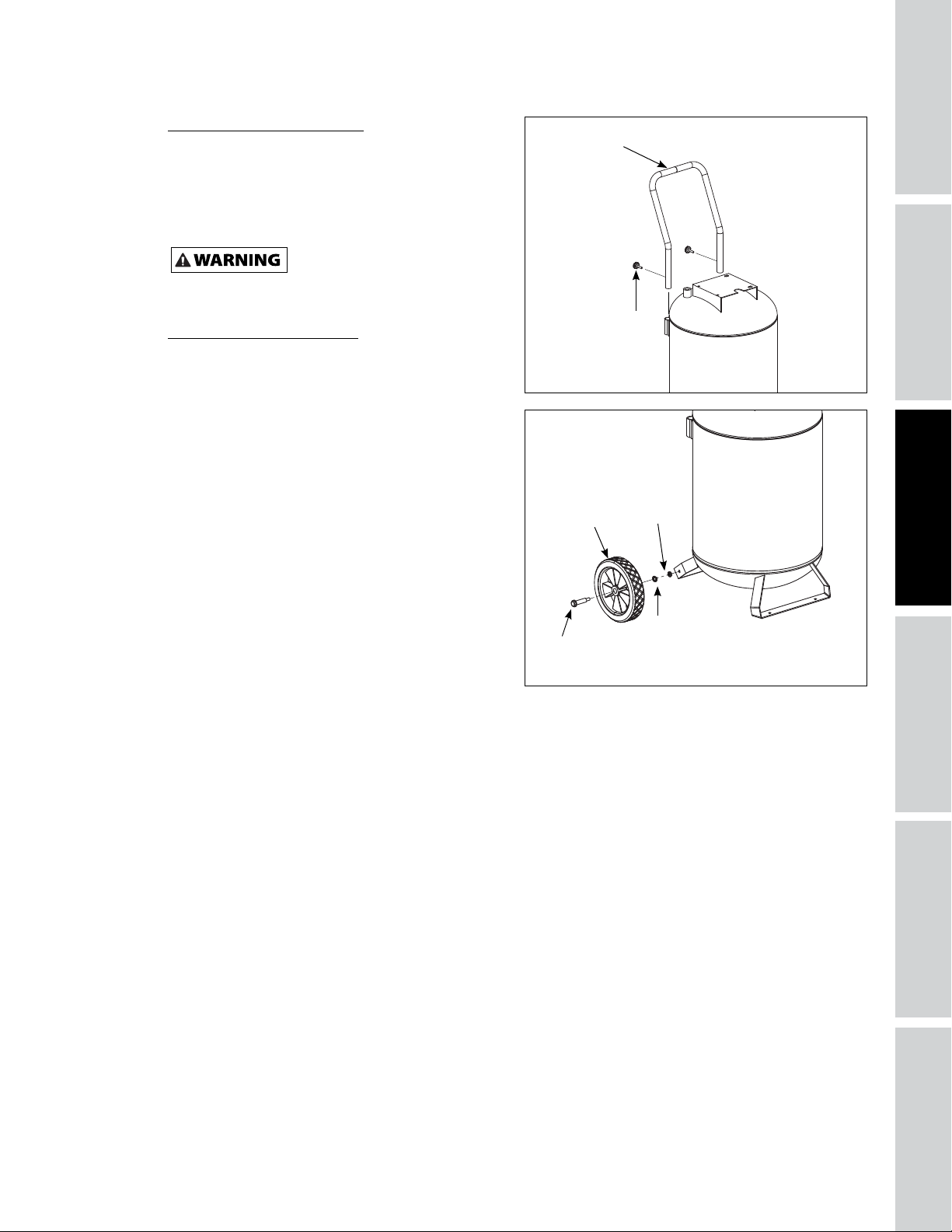
Handle Assembly (Figure 1)
1. Place ends of handle around tank and into the
mounting pipe. Align holes in handle to holes in
mounting pipe.
2. Assemble two (2) screws (from parts package)
through holes in mounting pipe and handle.
Tighten screws.
Never use the handle to lift the unit
completely off the ground. Only
use the handle to lift one end so the wheels may be used to
move the unit.
Wheel Assembly (Figure 2)
Wheel assembly kit includes:
- 2 wheels *
- 2 axle bolts *
- 2 washers *
- 2 nuts *
The items marked with an asterisk (*) were shipped
loose with the unit.
1. Wheel has an offset hub. Place wheel insert into
center of hub. With offset hub facing axle iron,
assemble axle bolt through washer and then holes
in wheel and axle iron.
2. Place lock washer on axle bolt. Then tighten nut
securely to threaded part of axle bolt.
3. Repeat procedure with other side.
Handle
Bolt
Figure 1 - Handle Assembly
Wheel
Axle
Figure 2 - Wheel Assembly
Nut
Spring Washer
SPECIFICATIONS
SAFETY /
INSTALLATION
ASSEMBLY /
TROUBLESHOOTINGOPERATION
MAINTENANCE /
REPAIR
5
Page 8
SAFETY /
ASSEMBLY /
GETTING TO KNOW YOUR UNIT
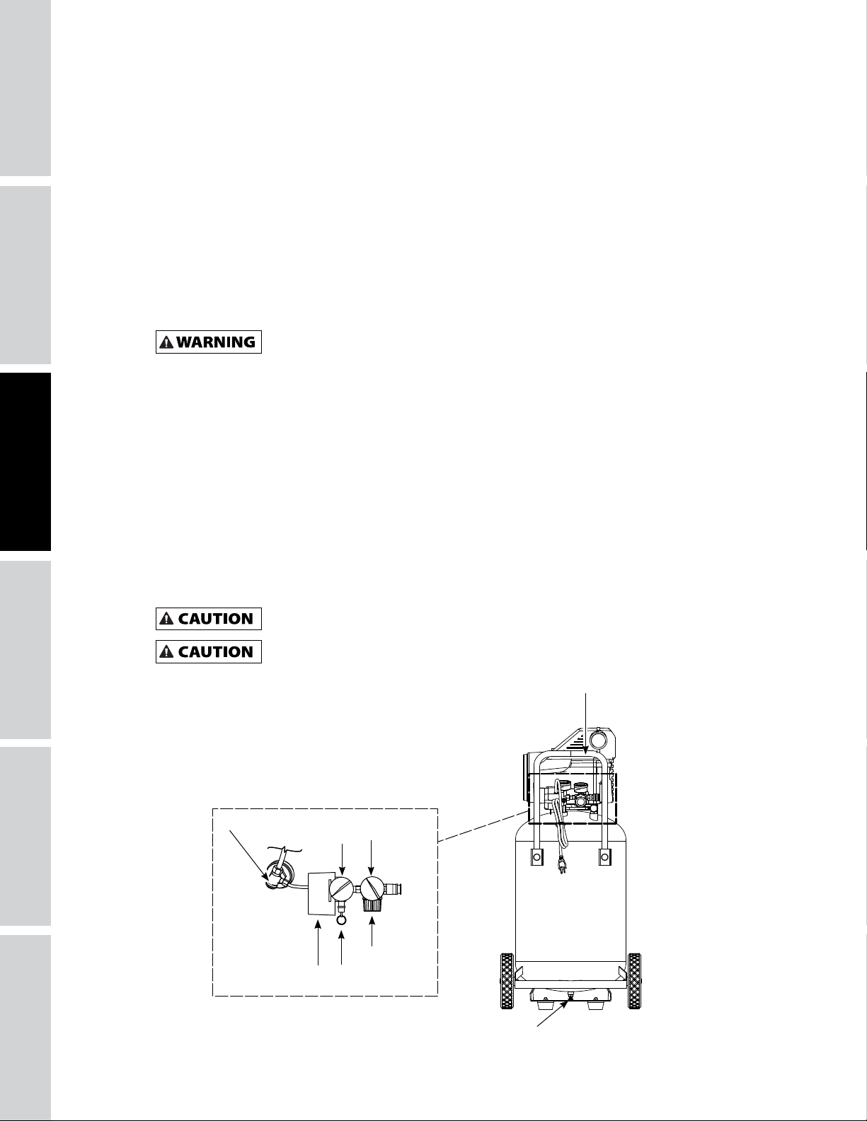
Pressure Switch - Auto/Off Switch - In the “AUTO” position, the compressor shuts off automatically when
tank pressure reaches the maximum preset pressure. In the “OFF” position, the compressor will not operate.
This switch should be in the “OFF” position when connecting or disconnecting the power cord from the
electrical outlet.
GETTING STARTED
SPECIFICATIONS
INSTALLATION
Regulator - The regulator controls the amount of air pressure at the hose outlet.
ASME Safety Valve - This valve automatically releases air if the tank pressure exceeds the preset
maximum.
Exhaust Tube - This tube carries compressed air from the pump to the check valve. This tube becomes very
hot during use. To avoid the risk of severe burns, never touch the discharge tube.
Check Valve - One-way valve that allows air to enter the tank, but prevents air in the tank from flowing
back into the compressor pump.
Handle - Designed to move the compressor.
Drain Valve - This valve is located on the bottom of the tank. Use this valve to drain moisture from the
tank daily to reduce the risk of corrosion.
Pressure Gauges - These gauges will show air pressure in the compressor tank and at the compressor
outlet.
Outlet Pressure Gauge - Will show air pressure at the outlet in pounds per square inch (psi). Make sure
this gauge reads ZERO (by adjusting regulator knob fully counterclockwise) before changing air tools or
disconnecting air hose from outlet.
Tank Pressure Gauge - Will show air pressure in tank while the compressor is running, indicating
compressor is building pressure properly. This gauge will show maximum pressure of compressor when it
shuts off automatically at the pressure switch.
Never use the handle on wheeled units to lift the unit completely off the ground.
Motor Reset - (not shown, located inside motor). Designed to keep the motor from overheating. The
motor has an auto reset protector. To reset once the motor has cooled, turn the pressure switch to the OFF
position, then to the AUTO position.
This compressor is equipped with an overload protector which will shut off motor if it becomes
If the overload protector is actuated, the motor must be allowed to cool down for
overloaded.
approximately 30 minutes before it will reset.
Outlet
Check Valve
Pressure Switch
(AUTO / OFF)
Tank
Gauge
Safety Valve
Gauge
Regulator
Handle
Figure 3
Drain Valve
6
Page 9
INSTALLATION INSTRUCTIONS
Location
It is extremely important to install the compressor in a clean, dry, and well ventilated area. The compressor
must be placed on a firm, level surface where the surrounding air temperature will not be more than 100°F.
A minimum clearance of 18 inches between the compressor and a wall is required because objects could
obstruct air flow.
Do not locate the compressor air inlet near steam, paint spray, sandblast areas or any other
source of contamination. This debris will damage the motor.
Electrical Installation
All wiring and electrical connections should be performed by a qualified electrician.
Installation must be in accordance with local codes and national electrical codes.
Wiring
1. Local electrical wiring codes differ from area to area. Source wiring, plug and protector must be rated
for at least the amperage and voltage indicated on motor nameplate, and meet all electrical codes for
this minimum.
2. Use a slow blow fuse or a circuit breaker.
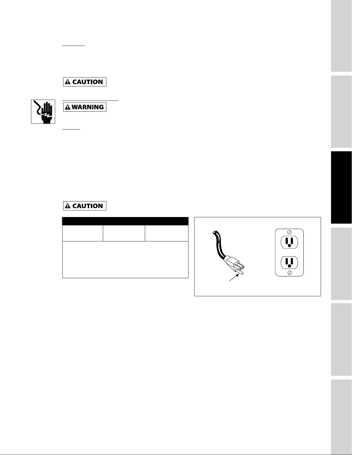
3. This product is for use on a nominal 120 volt circuit and has a grounding plug that looks like the plug
illustrated in Figure 4. Make sure the product is connected to an outlet having the same configuration
as the plug. This product must be grounded. In the event of an electrical short circuit, grounding
reduces risk of electrical shock by providing an escape wire for electric current. This product is equipped
with a cord having a grounding wire with an appropriate grounding plug. Plug must be plugged into
an outlet that is properly installed and grounded in accordance with all local codes and ordinances.
SPECIFICATIONS
SAFETY /
INSTALLATION
ASSEMBLY /
Overheating, short circuiting and fire damage will result from inadequate wiring.
Minimum Gauge of Extension Cord
25 ft. 50 ft. 100 ft.
14 12 10
Use of an extension cord may cause excess heat to
motor. This could lead to tripped breaker (at electrical
panel) or tripped thermal overload (on compressor
motor). If this occurs, eliminate extension cord and plug
compressor directly into electrical outlet. Avoid using
extension cords; use longer air hose(s) instead.
Grounded Outlet
Grounding
Pin
Figure 4 - Grounding Method
TROUBLESHOOTINGOPERATION
MAINTENANCE /
REPAIR
7
Page 10

SAFETY /
ASSEMBLY /
OPERATING INSTRUCTIONS
Before First Start-Up Break-In Procedure
(Complete this procedure before using compressor for the first time. Once completed, it is not necessary to
repeat.)
GETTING STARTED
SPECIFICATIONS
INSTALLATION
1. Open drain valve located on bottom of tank.
2. Turn ON / OFF switch to OFF position.
3. Plug in power cord.
4. Turn ON / OFF switch to ON position and run compressor for 30 minutes.
5. Turn ON / OFF switch to OFF position.
6. Unplug power cord.
7. Close drain valve.
The compressor is now ready for use.
Operating Procedure
1. Turn switch to OFF position and plug in power cord.
2. Turn regulator knob counterclockwise to close air flow.
3. Turn switch to AUTO position.
4. Compressor will build to maximum pressure and shut off.
5. With hose attached to outlet of compressor, attach tire chuck or other tool to open end of hose.
6. Adjust regulator to proper pressure for tool or tire. Operate tool per instructions.
As air is depleted from the tank by use of a tire chuck, tool, etc., the compressor will restart automatically
at its preset “cut-in” pressure. When a tool is being used continuously, the compressor will cycle on and off
automatically.
7. Turn switch to OFF position, unplug power cord and drain tank of air when finished using compressor.
IN COMPRESSED AIR
Moisture in compressed air will form into droplets as it comes from an air compressor pump. When
humidity is high or when a compressor is in continuous use for an extended period of time, this
moisture will collect in the tank. When using a paint spray or sandblast gun, this water will be carried
from the tank through the hose, and out of the gun as droplets mixed with the spray material.
IMPORTANT: This condensation will cause water spots in a paint job, especially when spraying other
than water based paints. If sandblasting, it will cause the sand to cake and clog the gun, rendering it
ineffective.
A filter in the air line, located as near to the gun as possible, will help eliminate this moisture.
8
Page 11

TROUBLESHOOTING GUIDE
SYMPTOM POSSIBLE CAUSE(S) CORRECTIVE ACTION
Compressor will not run 1. Switch in OFF position 1. Make sure compressor is plugged in and switch is
ON.
2. No electrical power at wall outlet 2. Check circuit breaker or fuse at electrical panel.
Fuses blow / circuit breaker
trips repeatedly
3. Compressor has reached automatic
shut-off pressure
4. Motor overheated 4. Allow compressor to cool for approximately 30
5. Loose electrical connection 5. Check all electrical connections.
6. ON / OFF switch bad 6. Replace ON / OFF switch.
7. Pressure switch bad 7. Replace pressure switch.
8. Defective motor 8. Replace pump / motor assembly.
1. Incorrect size fuse, circuit overloaded 1. Check for proper fuse, use time-delay fuse.
2. Extension cord usage - wrong gauge
wire and/or too long
3. Worn check valve 3. Replace check valve.
3. Release air from tank until compressor restarts
automatically.
minutes so thermal overload switch will reset. Make
sure compressor is run in a clean, well-ventilated
area where temperature will not exceed 100°F.
Disconnect other electrical appliances from circuit
or operate compressor on its own branch circuit.
2. Remove extension cord or refer to Extension Cord
Chart on page 5.
SPECIFICATIONS
SAFETY /
INSTALLATION
ASSEMBLY /
Tank pressure drops when
compressor shuts off
Compressor runs continuously
and / or air output is lower
than normal / low discharge
pressure
Do not disassemble check valve
tank.
4. Defective unloader valve (on
pressure switch)
5. Defective motor capacitor(s) 5. Replace capacitor(s).
6. Defective motor 6. Replace motor.
1. Loose connections (fittings, tubing,
etc.)
2. Open tank drain valve 2. Close tank drain valve.
3. Tank leaks 3. Check tank for leaks with soap and water solution.
1. Excessive air usage 1. Decrease air usage; compressor not large enough
2. Clogged intake filter 2. Clean or replace filter.
3. Open tank drain valve 3. Close tank drain valve.
4. Air leaks in piping (on machine or in
outside system)
5. Piston ring worn 5. Replace piston and cylinder.
6. Broken valve (in pump) 6. Replace valve.
7. Tank leaks 7. Check tank for leaks with soap and water solution.
8. Defective pressure switch 8. Replace switch.
4. Replace unloader valve.
1. Check all connections with soap and water solution.
Tighten; or remove and apply pipe dope or pipe
tape to the threads, then reassemble.
If leak is detected, tank must be replaced with
genuine replacement part.
for air requirement.
4. Check all connections with soap and water solution.
Tighten; or remove and apply pipe dope or pipe
tape to the threads, then reassemble.
If leak is detected, tank must be replaced with
genuine replacement part.
with air pressure in tank; bleed
TROUBLESHOOTINGOPERATION
MAINTENANCE /
REPAIR
9
Page 12

SAFETY /
ASSEMBLY /
TROUBLESHOOTING GUIDE (CONTINUED)
SYMPTOM POSSIBLE CAUSE(S) CORRECTIVE ACTION
GETTING STARTED
SPECIFICATIONS
INSTALLATION
Excessive moisture in discharge
air
Knocks, rattles, and/or
excessive vibration
Compressor runs continuously
and safety valve opens as
pressure rises
Air leaking from unloader
valve on pressure switch
1. Excessive water in tank 1. Drain tank.
2. High humidity 2. Move to area of less humidity; use air line filter.
1. Loose mounting bolts 1. Tighten bolts.
2. Tank not level 2. Use sturdy wedge / object to bring tank to level
3. Cylinder or piston is worn/scored 3. Replace or repair as necessary.
1. Defective pressure switch 1. Replace switch.
2. Defective safety valve 2. Replace safety valve with genuine replacement
1. Check valve stuck in an open position 1. Replace check valve.
2. Unloader valve stuck in open
position
position.
part.
2. Replace unloader valve.
Do not disassemble check valve
with air pressure in tank; bleed
tank.
10
Page 13
MAINTENANCE AND INSPECTION INSTRUCTIONS
Disconnect, tag and lock out power source, then release all pressure from the system
Check compressor often for any visible problems and follow maintenance procedures each time compressor
is used.
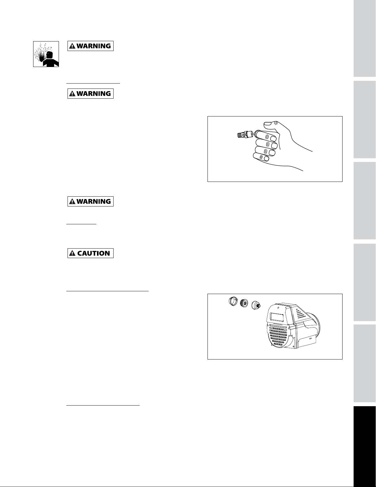
ASME Safety Valve
Check the safety valve by performing the following steps:
1. Plug the compressor in and run until shut off
pressure is reached.
2. Wearing safety glasses, pull the ring on the safety
valve to release pressure from compressor tank.
Use your other hand to deflect fast-moving air
from being directed toward your face.
3. The safety valve should automatically close at
approximately 40 psi - 50 psi. If the safety valve
does not allow air to be released when you pull
on the ring, or if it does not close automatically, it
MUST be replaced.
before attempting to install, service, relocate or perform any maintenance.
Do not remove or attempt to adjust the safety valve!
Safety valve must be replaced if it cannot be actuated or it leaks air after ring is released.
Figure 5
SPECIFICATIONS
SAFETY /
INSTALLATION
ASSEMBLY /
Drain Tank
1. Turn compressor off and release pressure from system. (To release pressure from system, pull ring on
ASME safety valve. Deflect escaping air by shielding valve with one hand as you pull ring with other
hand.) Pull ring until tank is empty.
A large amount of fast moving air will be released when the safety valve is opened with
pressure in the tank. Wear ANSI approved Z87.1 safety glasses.
2. Drain moisture from tank by opening drain valve underneath tank. Tilt tank to remove all moisture.
3. Clean dust and dirt from tank, air lines and pump cover while compressor is still OFF.
Intake Air Filter Maintenance
Removal, Inspection and Replacement (Figure 6).
The intake filter element should be removed and
checked periodically. A clogged intake filter can
decrease compressor performance and cause the
compressor to overheat.
1. Remove bolt.
2. Remove the filter cover and filter element. Inspect
each piece.
3. If the filter element is dirty or clogged, replace it.
4. Reinstall filter, cover, and bolt. Thread the intake air filter into the threaded opening in the side of the
compressor head as illustrated in Figure 6 before use.
IMPORTANT: Locate unit as far from spraying area as hose will allow to prevent overspray from clogging
filter.
Figure 6 - Intake Filter Maintenance
TROUBLESHOOTINGOPERATION
End of Operation/Storage
1. Turn AUTO/OFF switch to the OFF position.
2. Unplug power cord from wall outlet and wrap around handle to prevent damage when not in use.
3. Wearing safety glasses drain tank of air by pulling the ring on the safety valve. Use other hand to
deflect fast moving air from being directed toward your face.
4. Drain tank of condensation by opening drain valve on bottom of tank. Tank pressure should be below
10 psi when draining tank.
11
REPAIR
MAINTENANCE /
Page 14

MAINTENANCE AND INSPECTION INSTRUCTIONS (CONTINUED)
5. Air hose should be disconnected from compressor and hung open ends down to allow any moisture to
drain.
6. Compressor and hose should be stored in a cool, dry place.
SAFETY /
ASSEMBLY /
GETTING STARTED
SPECIFICATIONS
INSTALLATION
Technical Service
For information regarding the operation or repair of this product, please visit www.campbellhausfeld.com.
MAINTENANCE SCHEDULE
OPERATION DAILY WEEKLY MONTHLY
DRAIN TANK
CHECK AIR FILTER
CHECK SAFETY VALVE
CLEAN UNIT
l
l
l
l
12
Page 15

NOTES
SPECIFICATIONS
SAFETY /
INSTALLATION
ASSEMBLY /
13
TROUBLESHOOTINGOPERATION
MAINTENANCE /
REPAIR
Page 16
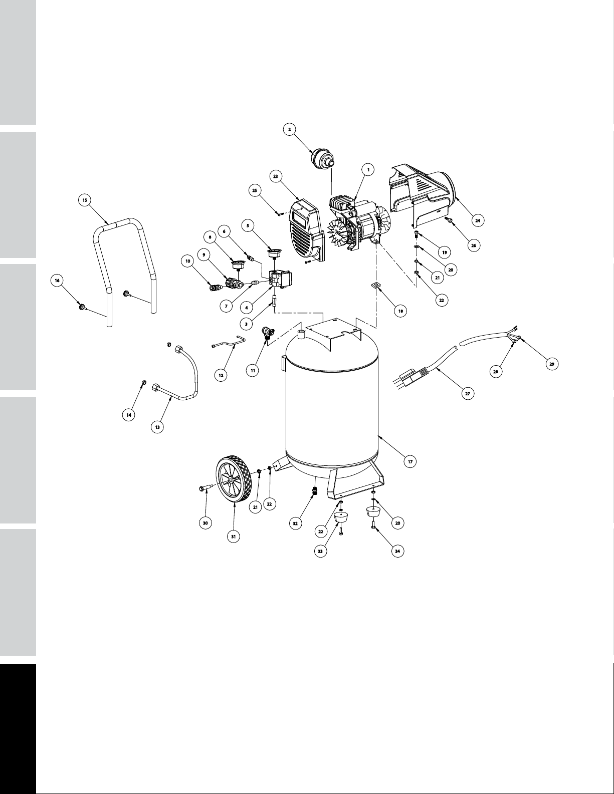
REPAIR PARTS ILLUSTRATION FOR DC200100
SAFETY /
ASSEMBLY /
GETTING STARTED
SPECIFICATIONS
INSTALLATION
2
23
15
8
9
10
16
12
25
5
6
7
4
3
11
1
24
26
19
20
21
22
18
28
27
29
14
13
22
21
30
31
32
22
33
20
34
For Repair Parts, visit www.campbellhausfeld.com
24 hours a day – 365 days a year
Please provide following information:
- Model number
- Serial number (if any)
- Part description and number as shown in parts list
17
14
Page 17

REPAIR PARTS LIST FOR DC200100
Ref.
No. Description Part Number Qty.
1 PUMP/MOTOR ASSEMBLY DC200102AV 1
2 FILTER DC200150AV 1
3 CONNECT -- 1
4 PRESSURE SWITCH
5 TANK GAUGE
6 SAFETY VALVE
7 CONNECT
8 OUTLET GAUGE
9 REGULATOR
10 COUPLER
11 CHECK VALVE ASSEMBLY DC200151AV 1
12 UNLOAD TUBE DC200152AV 1
13 EXHAUST TUBE
14 O-RING
15 HANDLE
16 BOLT
17 TANK -- 1
18 RUBBER PAD -- 4
19 M8X35 BOLT -- 4
20 M8 WASHER -- 4
21 M8 SPRING WASHER
22 M8 NUT
23 FRONT SHROUD -- 1
24 REAR SHROUD -- 1
25 SCREW -- 5
26 M5X12 BOLT -- 2
27 POWER CORD -- 1
28 CABLE CONNECT U -- 2
29 CABLE CONNECT O -- 1
30 AXLE
31 WHEEL
32 DRAIN VALVE DC200153AV 1
33 RUBBER FOOT -- 2
34 M8X20 BOLT -- 2
REPLACEMENT PARTS KITS
l
n
r
s
EXHAUST TUBE KIT DC200154AV
PRESSURE SWITCH AND REGULATOR KIT DC200155AV
WHEEL KIT DC200163AV
HANDLE KIT DC200164AV
n
n
n
n
n
n
n
l
l
s
s
r
r
r
r
1
1
1
SPECIFICATIONS
SAFETY /
1
1
1
1
1
2
INSTALLATION
ASSEMBLY /
1
2
4
4
2
2
TROUBLESHOOTINGOPERATION
MAINTENANCE /
REPAIR
15
Page 18

REPAIR PARTS ILLUSTRATION FOR DC200102AV
GETTING STARTED
1
SAFETY /
ASSEMBLY /
SPECIFICATIONS
INSTALLATION
3
4
8
10
11
14
15
18
19
20
21
22
24
16
17
2
5
6
7
9
12
13
7
2
43
42
41
40
26
43
45
44
33
28
32
31
30
38
39
37
36
35
34
27
26
23
25
28
29
For Repair Parts, visit www.campbellhausfeld.com
24 hours a day – 365 days a year
Please provide following information:
- Model number
- Serial number (if any)
- Part description and number as shown in parts list
16
Page 19

REPAIR PARTS LIST FOR DC200102AV
Ref.
No. Description Part Number Qty.
1 M6X35 BOLT
2 SPRING WASHER
3 CYLINDER HEAD
4 O-RING FOR VALVE PLATE
l
l
l
l s
4
5
1
1
UPPER
5 RELIEF VALVE
6 T-FITTING CONNECT
7 M4X8 SCREW
8 M4 SPRING WASHER
9 VALVE LIFT GUARD
10 OUTLET VALVE
11 VALVE PLATE
12 INLET VALVE
13 CAP OF INLET VALVE
14 O-RING FOR VALVE PLATE
n
n
s
s
s
s
s
s
s
s t
1
1
2
1
1
1
1
1
1
1
LOWER
15 CYLINDER
t
1
16 CRANKCASE -- 1
17 ECCENTRIC -- 1
18 M6X16 SCREW
19 COVER OF CONROD
20 PISTON RING
21 CONROD
22 FAN
23 M6 WASHER
24 M6X16 SCREW
25 M5X25 SCREW
26 M5 SPRING WASHER
27 M5 NUT
t
t
t
t
w
w
w
t
t
t
1
1
1
1
1
1
1
1
5
1
28 6203 BEARING -- 2
29 M6X40 SCREW -- 1
30 6204 BEARING -- 1
31 ROTOR -- 1
32 STATOR -- 1
33 WASHER -- 1
34 REAR MOTOR SEAT -- 1
35 M4X6 SCREW -- 1
36 M4 WASHER -- 1
37 GROUNDING SIGNAL -- 1
38 MOTOR FAN
u
1
Ref.
No. Description Part Number Qty.
39 CIRCLI
u
1
40 M5X10 BOLT -- 4
41 M3 SPRING WASHER -- 4
42 M3X6 SCREW -- 4
43 RUNNING CAPACITOR
44 M8 INNER WASHER
45 M8 NUT
u
u
u
2
2
2
REPAIR PARTS KITS
PUMP HEAD KIT DC200156AV
l
COLD START VALVE KIT DC200157AV
n
VALVE PLATE KIT DC200158AV
s
PISTON/CYLINDER KIT DC200159AV
t
CAPACITOR KIT DC200165AV
u
FRONT END FAN KIT DC200161AV
w
MOTOR FAN KIT DC200162AV
u
SPECIFICATIONS
SAFETY /
INSTALLATION
ASSEMBLY /
TROUBLESHOOTINGOPERATION
MAINTENANCE /
REPAIR
17
Page 20

Reminder: Keep your dated proof of purchase for warranty purposes! Attach it to this manual or file it for safekeeping.
LIMITED WARRANTY
1. DURATION: From the date of purchase by the original purchaser as follows: One Year.
2. WHO GIVES THIS WARRANTY (WARRANTOR): Campbell Hausfeld a Marmon/Berkshire Hathaway Company, 100 Production Drive,
Harrison, Ohio, 45030, Visit www.campbellhausfeld.com
3. WHO RECEIVES THIS WARRANTY (PURCHASER): The original purchaser (other than for purposes of resale) of the Campbell Hausfeld
compressor.
4. WHAT PRODUCT IS COVERED BY THIS WARRANTY: This Campbell Hausfeld air compressor.
5. WHAT IS COVERED UNDER THIS WARRANTY: Substantial defects due to material and workmanship with the exceptions noted below.
6. WHAT IS NOT COVERED UNDER THIS WARRANTY:
A. Implied warranties, including those of merchantability and FITNESS FOR A PARTICULAR PURPOSE ARE LIMITED FROM THE DATE
OF ORIGINAL PURCHASE AS STATED IN THE DURATION. If this compressor is used for commercial, industrial or rental purposes,
the warranty will apply for ninety (90) days from the date of purchase. Some States do not allow limitations on how long an
implied warranty lasts, so the above limitations may not apply to you.
B. ANY INCIDENTAL, INDIRECT, OR CONSEQUENTIAL LOSS, DAMAGE, OR EXPENSE THAT MAY RESULT FROM ANY DEFECT, FAILURE,
OR MALFUNCTION OF THE CAMPBELL HAUSFELD PRODUCT. Some States do not allow the exclusion or limitations of incidental
or consequential damages, so the above limitation or exclusion may not apply to you.
C. Any failure that results from an accident, purchaser’s abuse, neglect or failure to operate products in accordance with
instructions provided in the owner’s manual(s) supplied with compressor.
D. Pre-delivery service, e.g. assembly, oil or lubricants, and adjustment.
E. Items or service that are normally required to maintain the product, e.g. lubricants, filters and gaskets, etc.
F. Gasoline engines and components are expressly excluded from coverage under this limited warranty. The Purchaser must comply
with the warranty given by the engine manufacturer which is supplied with the product.
G. Additional items not covered under this warranty:
1. All Compressors
a. Any component damaged in shipment or any failure caused by installing or operating unit under conditions not in
accordance with installation and operation guidelines or damaged by contact with tools or surroundings.
b. Pump or valve failure caused by rain, excessive humidity, corrosive environments or other contaminants.
c. Cosmetic defects that do not interfere with compressor functionality.
d. Electric motors, check valves and pressure switches.
e. Drain cocks.
f. Damage due to incorrect voltage or improper wiring.
g. Other items not listed but considered general wear parts.
h. Pressure switches, air governors and safety valves modified from factory settings.
2. Lubricated Compressors
a. Pump wear or valve damage caused by using oil not specified.
b. Pump wear or valve damage caused by any oil contamination or by failure to follow proper oil maintenance
guidelines.
3. Belt Drive / Direct Drive / Gas Driven Compressors
a. Belts.
b. Ring wear or valve damage from inadequate filter maintenance.
c. Manually adjusted load/unload and throttle control devices.
7. RESPONSIBILITIES OF WARRANTOR UNDER THIS WARRANTY: Repair or replace, at Warrantor’s option, compressor or component
which is defective, has malfunctioned and/or failed to conform within the duration of the specific warranty period.
8. RESPONSIBILITIES OF PURCHASER UNDER THIS WARRANTY:
A. Provide dated proof of purchase and maintenance records.
B. Portable compressors or components must be delivered or shipped to the nearest Campbell Hausfeld Authorized Service Center.
Freight costs, if any, must be borne by the purchaser.
C. Use reasonable care in the operation and maintenance of the products as described in the owner’s manual(s).
9. WHEN WARRANTOR WILL PERFORM REPAIR OR REPLACEMENT UNDER THIS WARRANTY: Repair or replacement will be scheduled
and serviced according to the normal work flow at the servicing location, and depending on the availability of replacement parts.
This Limited Warranty applies in the U.S., Canada and Mexico only and gives you specific legal rights. You may also have other rights
which vary from State to State or country to country.
18
Page 21

Compresseur Sans Huile
Instructions d’Utilisation et Manual de Pièces
© 2017 Campbell Hausfeld
A Marmon/Berkshire Hathaway Company
Modèles: DC200100
FR
IN641601 3/17
Page 22

Lire et conserver ces instructions. Il faut les lire attentivement avant de
commencer à assembler, installer, faire fonctionner ou entretenir l’appareil décrit.
Pour se protéger et protéger autrui, observer toutes les informations sur la
sécurité. Négliger d’appliquer ces instructions peut causer
des blessures et/ou des dommages matériels! Conserver ces instructions pour
consultation ultérieure.
RAPPEL: Conservez votre preuve d’achat datée aux fins de garantie! Attachez-le à
ce manuel ou classez-le pour le garder en sécurité.
Pour de l’information sur les pièces,
produits et services veuillez visiter
N° de modèle : _____________________
N° de série : _______________________
Date d’achat : _____________________
ENREGISTREZ VOTRE PRODUIT EN LIGNE MAINTENANT ! www.campbellhausfeld.com
LIRE ET SUIVRE TOUTES LES INSTRUCTIONS • CONSERVER CES INSTRUCTIONS • NE PAS JETER
www.campbellhausfeld.com
Campbell Hausfeld
100 Production Drive
Harrison, Ohio 45030
Page 23

AVANT DE COMMENCER
Description
Ce compresseur résidentiel sans huile est conçu pour les bricoleurs avec une variété de travaux résidentiels
et automobiles. Ces compresseurs actionnent les pistolets vaporisateurs, les clés à chocs, et autres outils. L’air
comprimé produit par ce modèle va contenir de l’humidité. Installer un filtre ou un sécheur d’air si votre
application requiert de l’air sec.
DÉBALLAGE
Ne pas soulever ni déplacer le modèle sans équipement convenable et s’assurer que le modèle
refroidisseurs. Ne pas utiliser le modèle pour soulever d’autre équipement qui est attaché au compresseur.
Dès que l’appareil est déballé, l’inspecter attentivement pour tout signe de dommages en transit. Vérifier
s’il y a des pièces desserrées, manquantes ou endommagées. Vérifier pour s’assurer que tous les accessoires
fournis sont inclus avec l’appareil. Pour toutes questions, pièces endommagées ou manquantes, veuillez
visiter www.campbellhausfeld.com pour l’assistance à la clientèle.
SÉCURITÉ / CARACTÉRISTIQUES
soit bien fixé à l’appareil de levage. Ne pas soulever le modèle avec les tuyaux ou les
ARRÊT!
NE PAS RENVOYER LE PRODUIT AU MARCHAND!
Ne pas utiliser un modèle qui a été endommagé pendant le transport, la manipulation ou
l’utilisation. Le dommage peut résulter en explosion et peut causer des blessures ou dégâts
matériels.
INSTRUCTIONS GÉNÉRALES DE SÉCURITÉ
Directives De Sécurité
Ce manuel contient de l’information très importante qui est fournie pour la SÉCURITÉ et pour ÉVITER LES
PROBLÈMES D’ÉQUIPEMENT. Rechercher les symboles suivants pour cette information.
Danger indique une situation dangereuse imminente qui MÈNERA à la mort ou à des blessures
Avertissement indique une situation potentiellement dangereuse qui, si elle n’est pas évitée,
Attention indique une situation potentiellement dangereuse qui, si elle n’est pas évitée, PEUT
Avis indique de l’information importante qui pourrait endommager l’équipement si elle n’est
IMPORTANT ou REMARQUE: Information qui exige une attention spéciale.
Symboles De Sécurité
Les symboles de sécurité suivants apparaissent dans l’ensemble de ce manuel pour vous aviser des dangers
et précautions importants de sécurité.
graves si elle n’est pas évitée.
POURRAIT mener à la mort ou à de graves blessures.
mener à des blessures mineures ou modérées.
pas respectée.
ASSEMBLAGE /
INSTALLATION
UTILISATION
DÉPANNAGE
Porter une
protection oculaire
et un masque
Risque de
choc
MANUAL
Lire le manuel
d’abord
Risque de
pression
Portez une
protection
oculaire et
auditive
Risque
d’incendie
Fr1
Risque
de pièces
chaudes
Risque
d’explosion
ENTRETIEN /
RÉPARATION
Page 24

INSTRUCTIONS GÉNÉRALES DE SÉCURITÉ (SUITE)
Proposition 65 de Californie
Ce produit ou son cordon peuvent contenir des produits chimiques qui, de l’avis de l’État de
DÉMARRAGE
DE L’APPAREIL
SÉCURITÉ / CARACTÉRISTIQUES
INSTALLATION
ASSEMBLAGE /
reproduction. Lavez-vous les mains après la manipulation.
Vous pouvez créer de la poussière en coupant, ponçant, perçant ou meulant les
poussière contient souvent des produits chimiques reconnus pour causer le cancer, les déformations congénitales.
Importantes Instructions de Sécurité
S’il vous plaît lire et conserver ces instructions. Lire attentivement avant de monter, installer, utiliser ou de procéder à
l’entretien du produit décrit. Se protéger ainsi que les autres en observant toutes les instructions de sécurité, sinon, il y a
risque de blessure et/ou dégâts matériels! Conserver ces instructions comme référence.
Ce manuel contient des informations concernant la sécurité, le fonctionnement et l’entretien. Si vous avez
des questions, veuillez visiter www.campbellhausfeld.com pour l’assistance à la clientèle.
Ce compresseur/pompe n’est pas équipé pour et ne devrait pas être utilisé “comme soi” pour fournir de
l’air respirable. Pour les applications d’air pour la consommation humaine, il est nécessaire d’équiper le
compresseur d’air/pompe avec de l’équipement de sécurité en canalisation et d’alarme. Cet équipement
additionnel est nécessaire pour filtrer et purifier l’air afin d’atteindre les spécifications minimales pour
la respiration Grade D décrite dans le Compressed Gas Association Commodity Specification G 7.1,
OSHA 29 CFR 1910. 134, and/or Canadian Standards Associations (CSA).
DÉNÉGATION DES GARANTIES
Si le compresseur est utilisé pour les applications d’air respirable et l’équipement de sécurité en
canalisation et d’alarme n’est pas utilisé simultanément, les garanties en existance seront annulées, et
Campbell Hausfeld dénie toute responsabilité pour n’importe quelle perte, blessure ou dommage.
Californie, causent le cancer et des anomalies congénitales ou autres problèmes de
matériaux tels que le bois, la peinture, le métal, le béton, le ciment ou autre maçonnerie. Cette
AVERTISSEMENT D’AIR RESPIRABLE
UTILISATION
DÉPANNAGE
MANUAL
Généralités sur la Sécurité
Puisque le compresseur d’air et les autres composants (article pompe, pistolet de pulvérisation, filtres,
lubrifiants, tuyaux, etc.) utilisés font partie d’un système de pompage à haute pression, les précautions de
sécurité suivantes doivent être prises en considération à tout moment :
par surtension, le mettre sur OFF après chaque utilisation.
1. Lire attentivement tous manuels compris avec ce produit. Se familiariser avec ce produit, ses
commandes et son utilisation.
2. Suivre tous les codes de sécurité et d’électricité locaux ainsi que les codes des É-U; National Electrical
Codes (NEC) et Occupational Safety and Health Act (OSHA).
3. Seules les personnes bien familiarisées avec ces règlements d’utilisation doivent être autorisées à se
servir du compresseur.
4. Garder les visiteurs à l’écart de/et NE JAMAIS permettre les enfants dans l’endroit de travail.
5. Utiliser des lunettes de sécurité et la protection auditive pendant l’utilisation du modèle.
6. Ne pas se tenir debout sur/ni utiliser le modèle comme une prise à main.
7. Inspecter le système d’air comprimé et pièces détachées électriques pour toute indication de dommage,
détérioration, faiblesse ou fuites avant chaque utilisation. Réparer ou remplacer toutes pièces
défectueuses avant l’utilisation.
8. Inspecter le degré de serrage de toutes les attaches par intervalles régulières.
Les moteurs, l’équipement et les commandes électriques peuvent causer des arcs
le modèle près d’un gaz ou d’une vapeur inflammable. Ne jamais entreposer les liquides ou gaz inflammables près du
compresseur.
Ne pas faire fonctionner sans supervision. Laisser le compresseur sur la position AUTO peut
causer un démarrage accidentel. Pour éviter un démarrage accidentel et de possibles dommages
électriques qui peuvent allumer un gaz ou une vapeur inflammable. Ne jamais utiliser ou réparer
Fr2
Page 25

DIRECTIVES DE SÉCURITÉ (SUITE)
Les pièces du compresseur peuvent être chaudes même si le modèle est hors circuit.
9. Garder les doigts à l’écart du compresseur; les pièces mobiles et chaudes peuvent causer des blessures
et/ou des brûlures.
10. Si l’équipement vibre anormalement, ARRÊTER le moteur et l’inspecter immédiatement. La vibration est
généralement une indication d’un problème.
11. Pour réduire le risque d’incendie, garder l’extérieur du moteur libre d’huile, de solvants et de graisse
excessive.
Ne jamais enlever ou essayer d’ajuster la soupape de sûreté. Tenir la soupape de
sûreté libre de peinture et d’autres accumulations.
Ne jamais utiliser les tuyaux plastiques (CPV) pour l’air comprimé. Ceci peut causer des blessures
graves ou la mort.
Ne jamais essayer de réparer ni de modifier un réservoir! Le soudage, perçage ou
autre modifications peuvent affaiblir le réservoir et peuvent résulter en dommage de rupture ou
d’explosion. Toujours remplacer un réservoir usé, fendu ou endommagé.
Purger le liquide du réservoir quotidiennement.
12. L’accumulation d’humidité cause la rouille qui peut affaiblir le réservoir. Purger le réservoir
régulièrement et l’inspecter périodiquement pour la rouille et la corrosion ou autres conditions
dangereuses.
13. L’air mouvante peut agiter la poussière et le débris qui peut être dangereux. Dissiper l’air lentement en
purgeant l’humidité ou pendant la dépressurisation du système de compresseur.
SÉCURITÉ / CARACTÉRISTIQUES
ASSEMBLAGE /
INSTALLATION
Précautions de Pulvérisation
Ne pas pulvériser des matériaux inflammables près d’une flamme ni près d’une
source d’ignition y inclus le compresseur.
14. Ne pas fumer pendant la pulvérisation de peinture, d’insecticides ou d’autres substances inflammables.
15. Utiliser un masque / respirateur pendant la pulvérisation et pulvériser dans un endroit bien ventilé pour
éviter les dangers de santé et d’incendie.
16. Ne pas pulvériser vers le compresseur. Situer le compresseur aussi loin que possible de l’endroit de
pulvérisation pour minimiser l’accumulation de surpulvérisation sur le compresseur.
17. Pour pulvériser ou nettoyer avec des solvants ou produits chimiques toxiques, suivre les instructions
fournies par le fabricant du produit chimique.
UTILISATION
DÉPANNAGE
Fr3
ENTRETIEN /
RÉPARATION
Page 26

CARACTÉRISTIQUES TECHNIQUES
Moteur HP 1.3
Capacité du réservoir 75,71 L
DÉMARRAGE
DE L’APPAREIL
SÉCURITÉ / CARACTÉRISTIQUES
Étape Simple
Nombre de cylindres 1
Poussée d’air @ 90 psi 113,3 l/min
Tension 120
Amperes 14A
Hertz (cycles) 60
Pression maximale 150
Sortie du réservoir 1/4 po IM
Poids de l’unité 40,10 kg
DIMENSIONS
Leng. 50,55 cm
Larg. 47,50 cm
Haut. 106,93 cm
INSTALLATION
ASSEMBLAGE /
DC200100
DC200100
UTILISATION
DÉPANNAGE
Fr4
Page 27

INSTRUCTIONS D’ASSEMBLAGE
Assemblage de la Poignée (Figure 1)
1. Placer les extrémités de la poignée autour du
réservoir et dans le tuyau de montage. Aligner
les trous de la poignée avec les trous du tuyau
demontage.
2. Assembler deux (2) vis (fournies dans la trousse de
pièces) à travers les trous qui se trouvent dans le
tube de montage et la poignée. Resserrer les vis.
Ne jamais utiliser la poignée pour
soulever tout l’appareil du sol.
Utiliser seulement la poignée pour soulever une extrémité
pour que les roues puissent servir à déplacer l’appareil.
Assemblage de Roue (Figure 2)
La trousse d’assemblage de la roue inclut:
- 2 roues*
- 2 boulons d’essieu*
- 2 rondelles*
- 2 écrous*
Les articles portant un astérisque (*) ont été expédiés
desserrés avec l’appareil.
1. La roue a un moyeu décentré. Placer la garniture
de roue au centre du moyeu. Avec le moyeu
décentré face au fer d’essieu, assembler le boulon
d’essieu à travers la rondelle puis les trous dans la
roue et le fer d’essieu.
2. Placer la rondelle de blocage sur le boulon
d’essieu. Bien resserrer l’écrou sur la partie filetée
du boulon d’essieu.
3. Répéter la procédure de l’autre côté.
Poignée
Boulon
Figure 1 - Assemblage de la poignée
Roue
Axe
Figure 2 - Assemblage de la roue
Écrou
Rondelle élastique
SÉCURITÉ / CARACTÉRISTIQUES
ASSEMBLAGE /
INSTALLATION
UTILISATION
Fr5
DÉPANNAGE
ENTRETIEN /
RÉPARATION
Page 28

APPRENEZ À CONNAÎTRE VOTRE UNITÉ
Manostat - Interrupteur Auto /Off - Dans la position “AUTO”, le compresseur se coupe automatiquement
quand la pression du réservoir atteint la pression maximum réglée d’avance. Une fois que l’air est
usé du réservoir et baisse à une niveau réglé d’avance, le manostat remet le moteur en marche (on)
automatiquement. Dans la position “OFF”, le compresseur ne fonctionnera pas. Cet interrupteur devrait
DÉMARRAGE
DE L’APPAREIL
SÉCURITÉ / CARACTÉRISTIQUES
INSTALLATION
ASSEMBLAGE /
être dans la position “OFF” pendant le branchement ou le débranchement du cordon d’alimentation de la
prise de courant ou pendant le changement d’outils pneumatiques.
Régulateur - Le régulateur sert à régler la pression d’air à la sortie de tuyau.
Soupape de Sûreté ASME - Cette soupape laisse échapper l’air automatiquement si la pression du
réservoir dépasse la pression maximum réglée d’avance.
Tuyau de Décharge - Ce tuyau transporte l’air comprimé de la pompe au clapet. Ce tuyau devient très
chaud pendant l’utilisation. Pour éviter le risque des brûlures sévères, ne jamais toucher le tuyau de
décharge.
Clapet - Une soupape à sens unique qui permet l’arrivée d’air dans le réservoir mais ne permet pas que l’air
se recule dans la pompe.
Poignée - Conçue pour le déplacement du compresseur.
Robinet de Purge de Réservoir - Cette soupape est située au fond du réservoir. Utiliser cette soupape
pour purger l’humidité du réservoir quotidiennement afin de réduire le risque de corrosion.
Manomètre(s) - Ces manomètres indiquent la pression d’air dans le réservoir du compresseur et à la sortie
du compresseur.
Manomètre de sortie - Ce manomètre indique la pression d’air à la sortie, mesurée en kPa (psi). S’assurer
que le manomètre est à ZERO (en tournant le bouton du régulateur complètement dans le sens antihoraire)
avant de changer les outils ou de débrancher le tuyau de la sortie d’air.
Manomètre du réservoir - Ce manomètre indique la pression d’air dans le réservoir pendant le
fonctionnement du compresseur, ce qui confirme que le compresseur est en train d’augmenter la pression
de manière appropriée. Ce manomètre indique la pression maximum du compresseur quand’ il s’éteigne
automatiquement à la pression limite.
Réinitialisation du moteur - (non illustré, se trouve à l’intérieur du moteur).Conçu pour empêcher le
moteur de surchauffer. Le moteur a un protecteur de réinitialisation automatique. Pour réinitialiser après le
refroidissement du moteur, tourner le pressostat à la position « OFF » (arrêt) puis à la position « AUTO ».
Ne jamais utiliser la poignée sur les modèles avec roues pour soulever le modèle.
UTILISATION
DÉPANNAGE
Ce compresseur est doté d’un protecteur de surcharge qui coupera lemoteur s’ilsurchauffe.
Si le protecteur de surchauffe est activé, il faut laisser le moteur refroidir pendant environ 30
Figure 3
minutes avant deleréutiliser.
Clapet
Manostat (AUTO
Jauge du
réservoir
/ OFF)
Jauge de
sortie
Régulateur
Soupape de
Sûreté
Robinet de Purge
Poignée
Fr6
Page 29

INSTRUCTIONS D’INSTALLATION
Endroit
Il est extrêmement important d’installer le compresseur dans un endroit propre, sec et bien ventilé. Le
compresseur doit être placé sur une surface solide et à niveau dont la température ambiante ne dépasse pas
38°C (100°F).
Un espace libre minimum de 45,7 centimètres entre le compresseur et un mur est exigé pour éviter le
stoppage d’air par des objets.
Ne pas situer la prise d’air du compresseur près de la vapeur, un jet pulvérisé de peinture,
endroits de décapage au sable ou autre sources de contamination. Le débris endommagera le
moteur.
Installation Électrique
Seul un électricien qualifié doit effectuer l’installation électrique et raccordements
électriques. Respecter toutes les codes locaux et nationaux de l’électricité.
Câblage
1. Les codes de câblage électrique locaux diffèrent d’un endroit à l’autre. Le câblage source, la fiche et
le protecteur doivent être d’une valeur nominale d’au moins l’ampérage et la tension indiqués sur la
plaque signalétique du moteur et doivent répondre à tous les codes électriques pour ce minimum.
2. Utiliser un fusible à action retardée ou un disjoncteur.
3. Ce produit est conçu pour l’utilisation d’un circuit de 120 volts et a une fiche de mise à la terre comme
celle indiquée sur la Figure 4. S’assurer que l’appareil est branché à une prise de courant qui a la même
configuration que la fiche. Ce produit doit être mis à la terre. Dans l’évenement d’un court-circuit, la
mise à la terre diminue le risque de secousse électrique en fournissant un fil d’échappement pour le
courant électrique. Ce produit est équipé avec un cordon qui a un fil de terre avec une fiche de terre. La
fiche doit être branchée dans une prise de courant qui a été installée et mise à la terre correctement en
respectant tous les codes et règlements locaux.
SÉCURITÉ / CARACTÉRISTIQUES
ASSEMBLAGE /
INSTALLATION
Un câblage inadéquat cause la surchauffe, les court-circuit et les dommages d’incendie.
Calibre minimum de la rallonge
7,5 m 15 m 30 m
14 12 10
Utiliser une rallonge pourrait mener à une chaleur
excessive au moteur. Ceci pourrait mener au
déclenchement du disjoncteur (au panneau électrique)
ou au déclenchement de la surcharge thermique (sur le
moteur du compresseur). Si ceci se produit, éliminer la
rallonge et brancher le compresseur directement dans
la prise de courant. Éviter d'utiliser des rallonges, utiliser
plutôt un(des) tuyau(x) à air plus long(s).
Prise de Courant Mise à la
Broche de
Terre
Figure 4 - Méthode de Mise à la Terre
Terre
UTILISATION
DÉPANNAGE
ENTRETIEN /
RÉPARATION
Fr7
Page 30

DÉMARRAGE
MODE D’EMPLOI
DE L’APPAREIL
Avant le premier démarrage
Procédure de rodage
(Cette procédure doit être terminée avant d’utiliser le compresseur pour la première fois. Ensuite, il n’est
pas nécessaire de la refaire.)
1. Ouvrir le robinet de vidange au bas du réservoir.
2. Mettre l’interrupteur marche/arrêt à la position « OFF » (ARRÊT).
3. Brancher le cordon d’alimentation.
4. Mettre l’interrupteur marche/arrêt à la position « ON » (MARCHE) et faire fonctionner le compresseur
pendant 30 minutes.
5. Mettre l’interrupteur marche/arrêt à la position « OFF » (ARRÊT).
6. Débrancher le cordon d’alimentation.
7. Fermer le robinet de vidange.
Le compresseur est maintenant prêt à être utilisé.
SÉCURITÉ / CARACTÉRISTIQUES
INSTALLATION
ASSEMBLAGE /
UTILISATION
Procédure de fonctionnement
1. Tourner l’interrupteur à la position OFF et brancher le cordon d’alimentation.
2. Tourner le bouton du régulateur dans le sens antihoraire pour fermer le débit d’air.
3. Tourner l’interrupteur à la position AUTO.
4. Le compresseur accumulera la pression jusqu’à ce qu’il atteint la pression maximum et s’arrêtera.
5. Avec la tuyau branché à la sortie du compresseur, brancher le mandrin d’air ou un autre outil à
l’extrémité ouverte du tuyau.
6. Ajuster le régulateur à la bonne pression pour l’outil ou le pneu. Utiliser l’outil conformément aux
instructions.
Au fur et à mesure que l’air du réservoir est épuisé par le mandrin ou l’outil, etc., le compresseur se
met en marche automatiquement à la pression préréglé d’enclenchement. Quand on utilise un outil
continuellement, le compresseur commencera un cycle automatique de marche / arrêt.
7. Quand on a terminé d’utiliser le compresseur, tourner l’interrupteur à la position OFF, débrancher le
cordon d’alimentation et vidanger le réservoir d’air.
HUMIDITÉ DANS L’AIR COMPRIMÉ
L’humidité dans l’air comprimé forme des gouttelettes en arrivant de la pompe du compresseur d’air. Si
l’humidité est élevée, ou si le compresseur est utilisé continuellement, cette humidité s’accumulera dans
le réservoir. Pendant l’utilisation d’un pistolet à peinture ou d’un pistolet pour le décapage au sable,
cette eau sera transportée du réservoir par moyen du tuyau, et en forme de gouttelettes, mélangée
avec le matériel utilisé.
IMPORTANT: Cette condensation peut causer des taches d’eau sur votre travail de peinture, surtout
pendant la pulvérisation de peinture qui n’est pas à base d’eau. Pendant le décapage au sable, cette eau
servira à tenir le sable ensemble et causera une obstruction dans le pistolet.
Un filtre à air en canalisation situé aussi près du pistolet que possible aidera à éliminer cette humidité.
DÉPANNAGE
Fr8
Page 31

GUIDE DE DÉPANNAGE
SYMPTÔME CAUSE(S) POSSIBLE(S) ACTION CORRECTIVE
Le compresseur ne fonctionne
pas
Fusibles sautés/le disjoncteur se
déclenche à maintes reprises
Perte de pression dans le
réservoir à air quand le
compresseur se coupe
Le compresseur fonctionne
continuellement et/ou la sortie
d’air est plus basse que la
pression de décharge normale/
faible
1. Interrupteur en position “OFF” (arrêt) 1. S’assurer que le compresseur est branché et que
2. Aucun courant à la prise de courant
murale
3. Le compresseur a atteint la pression
d’arrêt automatique
4. Moteur surchauffé 4. Laisser le compresseur refroidir pendant 30 minutes
5. Connexions électriques dégagées 5. Vérifier toutes les connexions électriques.
6. Interrupteur MARCHE/ARRÊT
défectueux
7. Mauvais pressostat 7. Remplacer le pressostat.
8. Moteur défectueux 8. Remplacer le montage de pompe / moteur.
1. Taille de fusible incorrect, surcharge 1. Vérifier le type de fusible, utiliser un fusible à
2. Utilisation de rallonge - Calibre
inadéquat de la rallonge et/ou
rallonge trop longue
3. Soupape de retenue usée 3. Remplacer la soupape de retenue.
4. Soupape de décharge défectueuse
(sur le manostat)
5. Condensateur(s) de moteur
défectueux
6. Moteur défectueux 6. Remplacer le moteur.
1. Raccordements dégagés (raccords,
tuyaux, etc.)
2. Ouvrir le robinet de vidange du
réservoir
3. Fuite du réservoir 3. Vérifier le réservoir pour les fuites avec une solution
1. Utilisation d’air excessive 1. Réduire l’utilisation d’air; le compresseur n’est pas
2. Filtre d’entré obstrué 2. Nettoyer ou remplacer le filtre.
3. Ouvrir le robinet de vidange du
réservoir
4. Fuites d’air dans la tuyauterie (sur le
modèle ou dans le système extérieur)
5. Anneau de piston usé 5. Remplacer.
6. Soupape brisée (dans la pompe) 6. Remplacer la soupape.
7. Fuites du réservoir 7. Vérifier le réservoir pour les fuites avec une solution
8. Manostat défectueux 8. Remplacer le manostat.
l’interrupteur est à ON (marche).
2. Vérifier le disjoncteur ou les fusibles au coffret
électrique.
3. Dégager l’air du réservoir jusqu’à ce que le
compresseur redémarre automatiquement.
pour que l’interrupteur de surcharge thermique
se réinitialise. S’assurer que le compresseur
fonctionne dans un endroit propre, bien ventilé où
la température ne dépasse pas
38ºC (100 ° F).
6. Remplacer l’interrupteur ON/OFF.
retardement. Débrancher les autres appareils
électriques du circuit ou faire fonctionner le
compresseur sur un circuit unique.
2. Retirer la rallonge ou se reporter au Tableau de
Rallonges, page 15.
Ne pas démonter le clapet de
le réservoir ; purger le réservoir.
4. Remplacer la soupape de décharge.
5. Remplacer le condensateur(s).
1. Vérifier tous les raccordements avec de l’eau
savonneuse. Resserrer; ou retirer et appliquer aux
filets un produit scellant ou de ruban pour filets,
puis remonter.
2. Fermer le robinet de vidange du réservoir.
de savon et d’eau. S’il y a une fuite, le réservoir doit
être remplacé avec une pièce de rechange d’origine.
assez large pour la demande d’air.
3. Fermer le robinet de vidange du réservoir.
4. Vérifier tous les raccordements avec de l’eau
savonneuse. Resserrer; ou retirer et appliquer aux
filets un produit scellant ou de ruban pour filets,
puis remonter.
de savon et d’eau. S’il y a une fuite, le réservoir
doit être remplacé avec une pièce de rechange
d’origine.
non-retour avec de l’air dans
SÉCURITÉ / CARACTÉRISTIQUES
ASSEMBLAGE /
INSTALLATION
UTILISATION
DÉPANNAGE
ENTRETIEN /
RÉPARATION
Fr9
Page 32

GUIDE DE DÉPANNAGE
SYMPTÔME CAUSE(S) POSSIBLE(S) ACTION CORRECTIVE
Humidité excessive dans l’air
de débit
DÉMARRAGE
DE L’APPAREIL
SÉCURITÉ / CARACTÉRISTIQUES
Frappe, cogne et/ou vibration
excessive
Le compresseur fonctionne
continuellement et la soupape
de sécurité s’ouvre tandis que
la pression monte
Fuite d’air du clapet de
marche sur le manostat
1. Eau excessive dans le réservoir 1. Purger le réservoir.
2. Humidité élevée 2. Déplacer à un endroit moins humide; utiliser un
1. Boulons de montage desserrés 1. Resserrer les boulons.
2. Réservoir n’est pas à niveau 2. Utiliser un objet/coin solide pour ramener le
3. Le cylindre ou le piston est usé/
marqué
1. Manostat défectueux 1. Remplacer le manostat.
2. Soupape de sécurité défectueuse 2. Remplacer la soupape de sécurité avec des pièces de
1. Le clapet de non-retour colle en
position ouverte
2. Le clapet de marche colle en position
ouverte
filtre en canalisation d’air.
réservoir à la position à niveau.
3. Remplacer ou réparer au besoin.
rechange authentiques.
1. Remplacer le clapet de non-retour.
2. Remplacer le clapet de marche.
Ne pas démonter le clapet de
non-retour avec de l’air dans le
réservoir ; purger le réservoir.
INSTALLATION
ASSEMBLAGE /
UTILISATION
DÉPANNAGE
Fr10
Page 33

INSTRUCTIONS D’ENTRETIEN ET D’INSPECTION
Débrancher de la source de puissance et ensuite dissiper toute la pression du système
avant d’essayer d’installer, de réparer, de déplacer ou de procéder à l’entretien.
Inspecter le compresseur souvent et suivre les procédés d’entretien suivants pendant chaque utilisation du
compresseur.
SOUPAPE DE SÛRETÉ ASME
Ne jamais enlever ni essayer d’ajuster la soupape de sûreté !
Vérifier la soupape de sûreté de la manière suivante :
1. Brancher le compresseur et le faire fonctionner jusqu’à ce qu’il atteigne la pression d’arrêt (voir
procédure de fonctionnement).
2. Porter des lunettes de sécurité, tirer l’anneau sur
la soupape de sûreté pour dégager la pression
du réservoir du compresseur. Utiliser l’autre main
pour éloigner l’air se déplaçant rapidement vers le
visage.
3. La soupape de sûreté se fermera
automatiquement à environ
276 kPa - 345 kPa. Si la soupape ne laisse pas sortir
Figure 5
l’air en tirant sur l’anneau, ou si elle ne se ferme
pas automatiquement, il FAUT la remplacer.
S’il y a une fuite après que la soupape soit lâchée ou si la soupape ne fonctionne pas, elle
devrait être remplacée.
Purger le réservoir
1. Éteindre le compresseur et dégager la pression du système. (Pour dégager la pression du système, tirer
sur la soupape de sûreté ASME. Éloigner l’air qui s’échappe en protégeant la soupape d’une main tout
en tirant de l’autre.) Tirer l’anneau jusqu’à ce que le réservoir soit vide.
Une grande quantité d’air se déplaçant rapidement sera dégagée en ouvrant la soupape de
sûreté à cause de la pression dans le réservoir. Porter des lunettes de sécurité Z87.1 approuvées
par ANSI.
2. Drainer l’humidité du réservoir en ouvrant le robinet de vidange sous le réservoir. Pencher le réservoir
pour en retirer toute l’humidité.
3. Nettoyer la poussière et la saleté du réservoir, des conduites d’air et le couvercle de pompe tandis que le
compresseur est encore arrêté (OFF).
SÉCURITÉ / CARACTÉRISTIQUES
ASSEMBLAGE /
INSTALLATION
UTILISATION
ENTRETIEN DU FILTRE D’AIR D’ASPIRATION
Retrait, inspection et remplacement (Figure 6).
Il faut retirer l’élément du filtre d’aspiration et le
vérifier régulièrement. Un filtre d’aspiration bloqué
peut réduire la performance du compresseur et
provoquer une surchauffe du compresseur.
1. Retirer le boulon.
2. Retirer le couvercle du filtre et l’élément du filtre.
Inspecter chaque pièce.
3. Si l’élément du filtre est sale ou bloqué, remplacer
Figure 6 - Entretien du Filtre d’aspiration
l’élément.
4. Réinstaller le filtre, le couvercle et le boulon. Avant l’utilisation, vissez le filtre d’aspiration dans
l’ouverture filetée sur le côté de la tête de compresseur, comme illustré à la figure 6.
IMPORTANT: Placer l’unité aussi loin que possible du secteur de pulvérisation pour éviter que la
surpulvérisation bloque le filtre.
Conclusion du travail/Entreposage
1. Mettre l’interrupteur AUTO/OFF à la position « OFF » (ARRÊT).
2. Débrancher le cordon d’alimentation de la prise et l’enrouler autour du manche pour éviter de
l’endommager pendant l’entreposage.
Fr11
DÉPANNAGE
ENTRETIEN /
RÉPARATION
Page 34

INSTRUCTIONS D’ENTRETIEN ET D’INSPECTION (SUITE)
3. En portant des lunettes de sécurité, vidanger l’air du réservoir en tirant l’anneau de la soupape de
4. Vidanger le réservoir de toute condensation en ouvrant le robinet de vidange au fond du réservoir. La
DÉMARRAGE
DE L’APPAREIL
SÉCURITÉ / CARACTÉRISTIQUES
5. Le tuyau doit être débranché du compresseur et suspendu avec les bouts ouverts face en bas pour
6. Le compresseur et le tuyau doivent être rangés dans un endroit frais et sec.
Service Technique
Pour de l’information sur le fonctionnement ou la réparation de ce produit, veuillez visiter le www.
campbellhausfeld.com.
OPÉRATION QUOTIDIEN HEBDOMAD AIRE MENSUEL
PURGER LE RÉSERVOIR
VÉRIFIER LE FILTRE À AIR
VÉRIFIER LA SOUPAPE DE SÛRETÉ
NETTOYER LE MODÈLE
sécurité. À l’aide de l’autre main, détourner l’air se déplaçant rapidement, pour protéger le visage.
pression du réservoir doit être sous 69 kPa quand on vidange le réservoir.
laisser couler toute humidité.
HORAIRE D’ENTRETIEN
l
l
l
l
INSTALLATION
ASSEMBLAGE /
UTILISATION
DÉPANNAGE
Fr12
Page 35

NOTES
DE L’APPAREIL
DÉMARRAGE
SÉCURITÉ / CARACTÉRISTIQUES
ASSEMBLAGE /
INSTALLATION
UTILISATION
DÉPANNAGE
RÉPARATION
ENTRETIEN /
Fr13
Page 36

DÉMARRAGE
ILLUSTRATION DES PIÈCES DE REMPLACEMENT POUR LE DC200100
DE L’APPAREIL
2
15
SÉCURITÉ / CARACTÉRISTIQUES
16
INSTALLATION
ASSEMBLAGE /
14
23
25
5
6
8
9
10
7
4
3
12
13
11
1
24
26
19
20
21
22
18
28
27
29
17
UTILISATION
22
21
30
31
32
22
33
20
34
DÉPANNAGE
Pour les pièces de remplacement, visitez www.campbellhausfeld.com
24 heures par jour – 365 jours par an
Fournir les informations suivantes :
- Numéro de modèle
- Numéro de série (s’il y en a un)
- Description et numéro de pièce comme indiqué sur la liste des pièces
Fr14
Page 37

LISTE DES PIÈCES DE REMPLACEMENT POUR LE DC200100
N° de
réf. Description N° de pièce Qté
1 ASSEMBLAGE POMPE / MOTEUR DC200102AV 1
2 FILTRE DC200150AV 1
3 CONNECTEUR -- 1
4 MANOSTAT
5 MANOMÈTRE DU RÉSERVOIR
6 SOUPAPE DE SÉCURITÉ
7 CONNECTEUR
8 MANOMÈTRE DE SORTIE
9 RÉGULATEUR
10 COUPLEUR
11 ENSEMBLE DU CLAPET DE NON-RETOUR DC200151AV 1
12 TUYAU DE DÉLESTAGE DC200152AV 1
13 TUYAU D’ÉCHAPPEMENT
14 JOINT TORIQUE
15 POIGNÉE
16 BOULON
17 RÉSERVOIR -- 1
18 COUSSINET EN CAOUTCHOUC -- 4
19 BOULON M8 X 35 -- 4
20 RONDELLE M8 -- 4
21 RONDELLE ÉLASTIQUE M8
22 ÉCROU M8
23 PROTECTEUR AVANT -- 1
24 PROTECTEUR ARRIÈRE -- 1
25 VIS -- 5
26 BOULON M5 X 12 -- 2
27 CORDON D’ALIMENTATION -- 1
28 CÂBLE D'ALIMENTATION U -- 2
29 CÂBLE D'ALIMENTATION O -- 1
30 AXE
31 ROUE
32 VANNE DE DRAINAGE DC200153AV 1
33 PIED EN CAOUTCHOUC -- 2
34 BOULON M8 X 20 -- 2
NÉCESSAIRES DE PIÈCES DE RECHANGE
l
n
r
s
TROUSSE DU TUYAU D’ÉCHAPPEMENT DC200154AV
MANOSTAT ET TROUSSE DU RÉGULATEUR DC200155AV
TROUSSE DE ROUE DC200163AV
TROUSSE DE POIGNÉE DC200164AV
n
n
n
n
n
n
n
l
l
s
s
r
r
r
r
SÉCURITÉ / CARACTÉRISTIQUES
1
1
1
1
1
1
1
1
ASSEMBLAGE /
2
1
2
4
4
2
2
INSTALLATION
UTILISATION
DÉPANNAGE
ENTRETIEN /
RÉPARATION
Fr15
Page 38

DÉMARRAGE
ILLUSTRATION DES PIÈCES DE REMPLACEMENT POUR LE DC200102AV
DE L’APPAREIL
1
SÉCURITÉ / CARACTÉRISTIQUES
INSTALLATION
ASSEMBLAGE /
18
19
20
21
22
24
3
4
8
10
11
14
15
16
17
2
5
6
7
9
12
13
7
2
43
42
41
40
26
43
45
44
33
28
32
31
30
38
39
37
36
35
34
UTILISATION
27
26
23
25
28
29
DÉPANNAGE
Pour les pièces de remplacement, visitez www.campbellhausfeld.com
24 heures par jour – 365 jours par an
Fournir les informations suivantes :
- Numéro de modèle
- Numéro de série (s’il y en a un)
- Description et numéro de pièce comme indiqué sur la liste des pièces
Fr16
Page 39

LISTE DES PIÈCES DE REMPLACEMENT POUR LE DC200102AV
N°
de
réf. Description
1 BOULON M6 X 35
2 RONDELLE ÉLASTIQUE
3 CULASSE DE CYLINDRE
4 JOINT TORIQUE POUR LA
Numéro de
pièce : Qté
l
l
l
l s
PLAQUE PORTE-SOUPAPE
SUPÉRIEURE
5 SOUPAPE DE DECHARGE
6 CONNECTEUR DE TYPE T
7 VIS M4 X 8
8 RONDELLE ÉLASTIQUE M4
9 PROTECTION DE LA LEVÉE DE
n
n
s
s
s
SOUPAPE
10 SOUPAPE DE REFOULEMENT
11 PLAQUE PORTE-SOUPAPE
12 CLAPET D’ADMISSION
13 CAPOT DU CLAPET
s
s
s
s
D’ADMISSION
14 JOINT TORIQUE POUR LA
s t
PLAQUE PORTE-SOUPAPE
INFÉRIEURE
15 CYLINDRE
t
16 CARTER -- 1
17 EXCENTRIQUE -- 1
18 VIS M6 X 16
19 COUVERTURE DE LA BIELLE
20 SEGMENT DE PISTON
21 BIELLE
22 VENTILATEUR
23 RONDELLE M6
24 VIS M6 X 16
25 VIS M5 X 25
26 RONDELLE ÉLASTIQUE M5
27 ÉCROU M5
t
t
t
t
w
w
w
t
t
t
28 ROULEMENT 6203 -- 2
29 VIS M6 X 40 -- 1
30 ROULEMENT 6204 -- 1
31 ROTOR -- 1
32 STATOR -- 1
33 RONDELLE -- 1
34 SIÈGE DU MOTEUR ARRIÈRE -- 1
35 VIS M4 X 6 -- 1
N°
de
réf. Description
4
5
1
1
36 RONDELLE M4 -- 1
37 SIGNAL DE MISE À LA TERRE -- 1
38 VENTILATEUR DU MOTEUR
39 CERCLE
Numéro de
pièce : Qté
u
u
1
1
SÉCURITÉ / CARACTÉRISTIQUES
40 BOULON M5 X 10 -- 4
1
1
2
1
1
1
1
1
1
41 RONDELLE ÉLASTIQUE M3 -- 4
42 VIS M3 X 6 -- 4
43 CONDENSATEUR DE
u
FONCTIONNEMENT
44 RONDELLE INTÉRIEURE M8
45 ÉCROU M8
u
u
TROUSSES DE PIÈCES DE RÉPARATION
TROUSSE DE TÊTE DE POMPE DC200156AV
l
TROUSSE DE LA SOUPAPE DE
n
DC200157AV
DÉMARRAGE À FROID
TROUSSE DE PLAQUES
s
DC200158AV
2
2
2
ASSEMBLAGE /
INSTALLATION
PORTE-SOUPAPE
1
TROUSSE DU PISTON/
t
DC200159AV
CYLINDRE
TROUSSE DU CONDENSATEUR DC200165AV
1
u
TROUSSE DU VENTILATEUR
w
DC200161AV
DE L'EXTRÉMITÉ AVANT
TROUSSE DU VENTILATEUR
1
u
DU MOTEUR
DC200162AV
UTILISATION
1
1
1
1
1
1
1
5
DÉPANNAGE
1
ENTRETIEN /
RÉPARATION
Fr17
Page 40

Mémento: Gardez votre preuve datée d'achat à fin de la garantie! Joignez-la à ce manuel ou classez-la dans un dossier pour plus
de sécurité.
GARANTIE LIMITÉE
1. DURÉE: À partir de la date d’achat par l’acheteur original comme suit : Un An.
2. GARANTIE ACCORDÉE PAR (GARANT): Campbell Hausfeld a Marmon/Berkshire Hathaway Company, 100 Production Drive, Harrison,
Ohio, 45030, Visitez www.campbellhausfeld.com
3. BÉNÉFICIAIRE DE CETTE GARANTIE (ACHETEUR): L’acheteur original (sauf en cas de revente) du produit Campbell Hausfeld.
4. PRODUITS COUVERTS PAR CETTE GARANTIE: Ce compresseur d’air Campbell Hausfeld.
5. COUVERTURE DE LA PRÉSENTE GARANTIE: Défauts de matière et de fabrication considérables avec les exceptions indiquées
ci-dessous.
6. LA PRÉSENTE GARANTIE NE COUVRE PAS:
A. Les garanties implicites, y compris celles de commercialisabilité et D’ADAPTION À UNE FONCTION PARTICULIÈRE SONT LIMITÉES
À PARTIR DE LA DATE D’ACHAT INITIALE TELLE QU’INDIQUÉE DANS LA SECTION DURÉE. Si ce compresseur d’air est utilisé pour
une fonction commerciale ou pour la location, la durée de la garantie sera quatre-vingt-dix (90) jours à compté de la date
d’achat. Certaines Provinces /Certains États ne permettent pas de limitations de durée pour les garanties implicites, donc les
limitations précédentes peuvent ne pas s’appliquer dans ce cas.
B. TOUT DOMMAGE, PERTE OU DÉPENSE FORTUIT OU INDIRECT POUVANT RÉSULTER DE TOUT DÉFAUT, PANNE OU MAUVAIS
FONCTIONNEMENT DU PRODUIT CAMPBELL HAUSFELD. Quelques Provinces (États) n’autorisent pas l’exclusion ni la limitation
des dommages fortuits ou indirects. La limitation ou l’exclusion précédente peut ne donc pas s’appliquer.
C. Toute panne résultant d’un accident, d’une utilisation abusive, de la négligence ou d’une utilisation ne respectant pas les
instructions données dans le(s) manuel(s) accompagnant le produit.
D. Service avant livraison; par ex. le montage, l’huile ou les lubrifiants et les réglages.
E. Articles ou services qui sont exigés pour l’entretien normal du produit; par ex. lubrifiants, filtres et joints d’étanchéités.
F. Les moteurs à essence et les pièces détachées sont expressément exclus de cette garantie limitée. L’acheteur doit observer la
garantie du fabricant de moteur qui est fournie avec le produit.
G. Articles supplémentaires qui ne sont pas couverts sous cette garantie:
1. Tous les Compresseurs
a. Toutes pièces détachées endommagées pendant l’expédition, n’importe quelle panne causée par un montage
ou fonctionnement du modèle sous des conditions qui ne conforment pas aux directives de montage et de
fonctionnement ou dommage causée par le contact avec les outils ou les alentours.
b. La panne de la pompe ou de la soupape causée par la pluie, l’humidité excessive, un environnement corrosif ou autres
polluants.
c. Les défauts de forme qui n’ont pas d’effet sur le fonctionnement du compresseur.
d. Les moteurs électriques, les clapets, et les manostats.
e. Robinets de vidange.
F. Dommage dû à la tension ou installation de fils incorrecte.
g. Autres articles pas indiqués mais considérés pièces à fatigue générales.
h. Manostats, régulateurs d’air et soupapes de sûreté qui ont étés modifiés d’après les réglages de l’usine.
2. Compresseurs Graissés
a. Usure de la pompe ou dommage aux soupapes causé par l’utilisation d’huile non-spécifiée.
b. Usure de la pompe ou dommage aux soupapes causé par toute contamination d’huile ou par le manque de suivre les
directives d’entretien d’huile.
3. Commande par Courroie / Commande Directe / Compresseurs à Essence
a. Courroies
b. Usure de bagues causée par l’entretien de filtre insuffisant
c. Appareils manuels de chargement/déchargement et appareils de commande d’obturateur.
7. RESPONSABILITÉS DU GARANT AUX TERMES DE CETTE GARANTIE: Réparation ou remplacement, au choix du Garant, d’un
compresseur ou d’une pièce détachée qui se sont révélés défectueux ou qui ne se sont pas conformés pendant la durée de validité de
la garantie.
8. RESPONSABILITÉS DE L’ACHETEUR AUX TERMES DE CETTE GARANTIE:
A. Fournir une preuve d’achat datée et un état d’entretien.
B. La livraison ou expédition des compresseurs portatifs ou des pièces détachées au Centre De Service Autorisé Campbell Hausfeld.
Taux de frais, si applicables, sont la responsabilité de l’acheteur.
C. Utilisation et entretien du produit avec un soin raisonable, ainsi que le décri(vent)t le(s) manuel(s) d’utilisation.
9. RÉPARATION OU REMPLACEMENT EFFECTUÉ PAR LE GARANT AUX TERMES DE LA PRÉSENTE GARANTIE: La réparation ou le
remplacement sera prévu et exécuté en fonction de la charge de travail dans le centre de service et dépendra de la disponibilité des
pièces de rechange.
Cette Garantie Limitée s’applique aux É.-U., au Canada et au Mexique seulement et vous donne des droits juridiques précis. L’acheteur
peut également jouir d’autres droits qui varient d’une Province, d’un État ou d’un Pays à l’autre.
Fr18
Page 41

Compresores Sin Aceite
Manual de Instrucciones y Lista de Piezas
© 2017 Campbell Hausfeld
A Marmon/Berkshire Hathaway Company
Modelos: DC200100
SP
IN641601 3/17
Page 42

Por favor, lea y guarde estas instrucciones. Lealas cuidadosamente antes de tratar
de montar, instalar, operar o dar mantenimiento al producto aqui descrito.
Protejase usted mismo y a los demas observando toda la informacion de
seguridad. ¡El no cumplir con las instrucciones puede ocasionar daños, tanto
personales como a la propiedad! Guarde estas instrucciones para referencia en el
futuro.
RECORDATORIO: ¡guarde su comprobante de compra con fecha para fines de la
garantía! Adjúntela a este manual o archívela en lugar seguro.
Para ordenar repuestos, información de
Para ordenar repuestos, información de
productos y servicios visítenos en
productos y servicios visítenos en
www.campbellhausfeld.com
www.campbellhausfeld.com
Modelo #: _________________________
Modelo #: _________________________
Campbell Hausfeld
No. de Serie #: _____________________
No. de Serie #: _____________________
Fecha de Compra: __________________
Fecha de Compra: __________________
¡REGISTRE SU PRODUCTO EN LÍNEA AHORA MISMO! http://www.ch-commercial.com/registration/
¡REGISTRE SU PRODUCTO EN LÍNEA AHORA MISMO! www.campbellhausfeld.com
LEA Y SIGA TODAS LAS INSTRUCCIONES • GUARDE ESTAS INSTRUCCIONES • NO LAS DESECHE
LEA Y SIGA TODAS LAS INSTRUCCIONES • GUARDE ESTAS INSTRUCCIONES • NO LAS DESECHE
Campbell Hausfeld
100 Production Drive
100 Production Drive
Harrison, Ohio 45030
Harrison, Ohio 45030
Page 43

ANTES DE COMENZAR
Descripción
Este compresor sin aceite ha sido disenãdo para personas con habilidades manuales para llevar a cabo
una variedad de proyectos relacionados con el hogar o el vehículo. Estos compresores alimentan pistolas
de rociado, herramientas de impacto y otras herramientas. El aire comprimido producido por esta unidad
contiene humedad. Instale un filtro para agua o un secador de aire si la aplicación requiere de aire seco.
DESEMPAQUE
ALTO!
Nunca alce o mueva la unidad sin usar un equipo adecuado. Cerciórese de que la unidad esté
use la unidad para alzar otros equipos.
Después de desempacar la unidad, inspecciónela cuidadosamente para detectar cualquier daño que pueda
haber ocurrido durante el envío. Verifique que no haya piezas sueltas, faltantes ni dañadas. Asegúrese de
que todos los accesorios proporcionados vengan con la unidad. En caso de que tenga preguntas, o de que
haya piezas dañadas o faltantes, por favor visite www.campbellhausfeld.com para asistencia al cliente.
NE PAS RENVOYER LE PRODUIT AU MARCHAND!
No debe utilizar la unidad si se ha dañado durante el envío, manejo o uso. Los daños podrían
bien segura. No la tome por los tubos o piezas del sistema de enfriamiento para levantarla. No
ocasionar una explosión y ocasionarle heridas o daños a su propiedad.
INSTRUCCIONES GENERALES DE SEGURIDAD
Lineamientos de seguridad
Este manual contiene información que es muy importante que se conozca y comprenda. Esta información se
proporciona con fines de SEGURIDAD y para EVITAR PROBLEMAS CON EL EQUIPO. Para ayudar a reconocer
esta información, observe los siguientes símbolos.
Peligro indica una situación inminentemente peligrosa, que si no se evita, dará como resultado
Advertencia indica una situación potencialmente peligrosa, que si no se evita, PODRÍA ocasionar
Precaución indica una situación potencialmente peligrosa, que si no se evita, PUEDE dar como
Aviso indica una información importante, que de no seguirla, le podría ocasionar daños al
IMPORTANTE o NOTA: información que requiere atención especial.
la muerte o lesiones graves.
la muerte o lesiones graves.
resultado lesiones leves o moderadas.
equipo.
ESPECIFICACIONES
SEGURIDAD /
OPERACIONMONTAJE / INSTALACION
Símbolos de Seguridad
Los siguientes símbolos de seguridad aparecen a lo largo de este manual para advertirle de importantes
peligros y precauciones de seguridad.
MANUAL
Use protección
para los ojos y
máscara
Riesgo de
choque
eléctrico
Lea primero el
manual
Riesgo de
presión
Use
protectores
para la vista y
los oídos
Riesgo de
incendio
Riesgo
de piezas
calientes
Sp1
Riesgo de
explosión
IDENTIFICACION
DE PROBLEMAS
MANTENIMIENTO
/ REPARACION
Page 44

INSTRUCCIONES GENERALES DE SEGURIDAD (CONTINUACIÓN)
PARA COMENZAR
SEGURIDAD /
ESPECIFICACIONES
Proposición 65 de California
Este producto, o su cordón eléctrico, puede contener productos químicos conocidos por el
estado de California como causantes de cáncer y defectos de nacimiento u otros daños
reproductivos. Lave sus manos después de usar.
Cuando corta lija, taladra o pule materiales como por ejemplo madera, pintura,
metal, hormigón, cemento, u otro tipo de mampostería se puede producir polvo. Con frecuencia
este polvo contiene productos químicos que se conocen como causantes de cáncer, defectos congénitos u otros daños
reproductivos. Use equipo de protección.
Importantes Instrucciones De Seguridad
Sírvase leer y guardar estas instrucciones.Lea con cuidado antes de tratar de armar, instalar, manejar o darle servicio al
producto descrito en este manual. Protéjase Ud. y a los demás observando todas las reglas de seguridad. El no seguir las
instrucciones podría resultar en heridas y/o daños a su propiedad. Guarde este manual como referencia.
Este manual contiene información sobre seguridad, funcionamiento y mantenimiento. Si tiene preguntas,
por favor visite www.campbellhausfeld.com para asistencia al cliente.
ADVERTENCIA SOBRE EL AIRE RESPIRABLE
Este compresor/cabezal no viene listo de fábrica para suministrarle aire respirable. Antes de utilizarlos
con este fin, deberá instalarle un sistema de seguridad y alarma incorporado a la línea. Este sistema
adicional es necesario para filtrar y purificar el aire adecuadamente, para cumplir con las especificaciones
mínimas sobre aire respirable de Grado D descritas en la Especificación de Productos G 7.1 de la
Asociación de Aire Compri-mido. Igualmente, deberá cumplir los requisitos establecidos por el Artículo 29
CFR 1910. 134 de la Organización norteamericana OSHA y/o la Canadian Standards Associations (CSA).
RENUNCIA A LAS GARANTIAS
Si el compresor se utiliza para producir aire respirable SIN haberle instalado el sistema de seguridad y
alarma, todas la garantías se anularán y el fabricante no asumirá NINGUNA responsabilidad por pérdidas,
heridas personales o daños.
OPERACION MONTAJE / INSTALACION
DE PROBLEMAS
IDENTIFICACION
MANUAL
Generales Seguridad
Como el compresor de aire y otros componentes usados (bomba de material, pistolas pulverizadoras, filtros,
lubricadores, mangueras, etc.) intengran un sistema de alta presión, en todo momento deberá seguir las
siguientes medidas de seguridad:
No lo haga funcionar sin supervisión El dejar el compresor en la posición AUTO puede causar
que se encienda inadvertidamente. Para prevenir que eso ocurra y posibles daños por un
aumento de tensión, apague el compresor después de cada uso.
1. Lea con cuidado todos los manuales incluídos con este producto. Familiarícese con los controles y el uso
adecuado del equipo.
2. Siga todos los códigos de seguridad laboral y electricidad establecidos en su país, por ejemplo, los de la
NEC y OSHA en EUA.
3. Sólo personas bien familiarizadas con estas medidas de seguridad deben utilizar el compresor.
4. Mantenga a los visitantes alejados y NUNCA permita la presencia de niños en el área de trabajo.
5. Use anteojos de seguridad y protéjase los oídos para operar la unidad.
6. No se encarame sobre la unidad ni la use para sostenerse.
7. Antes de cada uso, revise el sistema de aire comprimido y los componentes eléctricos para ver si están
dañados, deteriorados o hay fugas. Antes de usarlo cerciórese de reemplazar las piezas defectuosas.
8. Chequée con frecuancia todas la conecciones y cerciórese de que estén bien apretadas.
Los motores, equipos eléctricos y controles, pueden ocasionar arcos eléctricos que se
encenderían con gases o vapores inflamables. Nunca utilice o repare el compresor cerca de gases
o vapores inflamables. Nunca almacene líquidos o gases inflamables cerca del compresor.
Sp2
Page 45

INFORMACIONES GENERALES DE SEGURIDAD (CONTINUACIÓN)
Las piezas del compresor podrían estar calientes, inclusive cuando la unidad esté
apagada.
9. Mantenga los dedos alejados del compresor cuando esté funcionando; las piezas en movimiento o
calientes le ocasionarían heridas y/o quemaduras.
10. Si el equipo comienza a vibrar excesivamente, APAGUE la unidad y chequéela inmediatamente para
determinar el problema. Generalmente, la vibración se debe a una falla.
11. Para reducir el peligro de incendios, mantenga el exterior del compresor limpio (sin aceite, solvente o
exceso de grasa).
DEBE instalarle una válvula de seguridad ASME que esté diseñada para presiones
máximas de 10,34 bar en el tanque de este compresor. Esta válvula debe estar diseñada para los
valores máximos de flujo y presión para proteger los componentes bajo presión contra el peligro de explosión.
Nunca use tuberías de plástico (PVC) en sistemas de aire comprimido. El compresor
sin las tapas de protección. El hacerlo podría ocasionarle heridas o daños a su propiedad.
¡Nunca trate de reparar o modificar el tanque! Al soldarlo, taladarle orificios o
modificarlo de cualquier otro modo éste se debilitaría y podría romperse o explotar. Siempre
reemplace los tanques desgastados, rotos o dañados.
Drene el tanque diariamente.
12. Los tanques se oxidan debido a la acumulación de humedad. Cerciórese de drenar el tanque con
regularidad e inspéccionelo periódicamente para ver si no está en buenas condiciones, por ejemplo si
está oxidado.
13. Si expulsa aire rápidamente podría levantar polvo o residuos dañinos. Libere el aire lentamente para
drenar el tanque o liberar la presión del compresor.
ESPECIFICACIONES
SEGURIDAD /
Precauciones Para Rociar
Nunca rocíe materiales inflamables cerca de llamas al descubierto o fuentes de
ignición, incluyendo el compresor.
14. No fume mientras esté rociando pintura, insecticidas u otras substancias inflamables.
15. Use una máscara / respirador cuando vaya a rociar y siempre rocíe en un área bien ventilada, para evitar
peligros de salud e incendios.
16. Nunca rocíe la pintura y
otros materiales, directamente hacia el compresor. Coloque el compresor lo más lejos posible del área
de trabajo, para minimizar la acumulación de residuos en el compresor.
17. Al rociar o limpiar con solventes o químicos tóxicos, siga las instrucciones del fabricante de dichos
químicos.
OPERACIONMONTAJE / INSTALACION
IDENTIFICACION
DE PROBLEMAS
MANTENIMIENTO
/ REPARACION
Sp3
Page 46

ESPECIFICACIONES
HP del motor 1.3
PARA COMENZAR
SEGURIDAD /
ESPECIFICACIONES
Capacidad del tanque 75,71 L
Fases Monofásico
Cantidad de cilindros 1
Suministro de aire @ 6,2 bar 113,3 l/min
Voltaje 120
Amperes 14A
Hertz (ciclos) 60
Presión máxima 150
Salida del tanque 1/4 pulg. IM
Peso de la unidad 40,10 kg
DIMENSIONS
Long. 50,55 cm
Anch. 47,50 cm
Alt. 106,93 cm
DC200100
DC200100
OPERACION MONTAJE / INSTALACION
DE PROBLEMAS
IDENTIFICACION
Sp4
Page 47

INSTRUCCIONES PARA EL ENSAMBLAJE
Ensamblaje del mango (Figura 1)
1. Coloque los extremos del mango alrededor del
tanque y dentro de la tubería de montaje. Alinee
los orificios del mango con los orificios de la
tubería de montaje.
2. Pase dos (2) tornillos (del paquete de partes) a
través de los agujeros en la tubería de montaje y
el mango. Apriete los tornillos.
Nunca use el
mango para levantar la unidad
completamente. Use el mango solamente para levantar un
extremo para que las ruedas puedan usarse para mover la
unidad.
Ensamblaje De La Rueda (Figura 2)
El juego del ensamble de la rueda incluye:
- 2 ruedas*
- 2 pernos de eje*
- 2 arandelas*
- 2 tuercas*
Los artículos marcados con asterisco (*) se despacharon
sueltos con la unidad.
1. La rueda tiene un cubo descentrado. Coloque la
inserción de la rueda en el centro del cubo. Con
el cubo descentrado hacia el hierro del eje, instale
el perno del eje a través de la arandela y de los
orificios de la rueda y del hierro del eje.
2. Coloque la arandela de presión en el perno del
eje. Luego apriete la tuerca de modo seguro a la
parte roscada del perno del eje.
3. Repita el procedimiento con el otro lado.
Mango
Perno
Figura 1 - Conjunto de manija
Rueda
Eje
Figura 2 - Conjunto de rueda
Tuerca
Arandela de
presión
ESPECIFICACIONES
SEGURIDAD /
OPERACIONMONTAJE / INSTALACION
Sp5
IDENTIFICACION
DE PROBLEMAS
MANTENIMIENTO
/ REPARACION
Page 48

CONOZCA SU UNIDAD
PARA COMENZAR
SEGURIDAD /
ESPECIFICACIONES
OPERACION MONTAJE / INSTALACION
Presostato - Sistema de encendido automático - En la posición “AUTO”, el compresor se apaga
automáticamente cuando la presión del tanque alcanza la presión máxima fijada. En la posición “OFF”,
el compresor no puede funcionar. El presostato debe colocarse en “OFF” para conectar o desconectar el
cordón eléctrico del tomacorrientes o para cambiar la herramienta neumática.
Regulador - El regulador controla la cantidad de presión de aire expulsada por la manguera.
Válvula de Seguridad ASME - Esta válvula automáticamente libera el aire si la presión del tanque excede
el valor máximo fijado de fábrica.
Tubería de Descarga - Este tubería transporta el aire comprimido del cabezal a la válvula de chequeo. Esta
tubería se calienta excesivamente durante el uso. Para evitar quemaduras graves, nunca la toque.
Válvula de Chequeo - Esta válvula solo permite que el aire entre al tanque y evita que éste se regrese al
cabezal.
Mango - Diseñado para mover el compresor.
Nunca use el mango de las unidades con ruedas para levantar completamente la unidad.
Válvula de Drenaje - Esta válvula está ubicada debajo del tanque. Úsela para drenar la humedad del
tanque diariamente, para evitar que el tanque se oxide.
Manómetros - Estos manómetros indican la presión de aire en el tanque del compresor y a la salida del
compresor.
Manómetro de salida - Indica la presión de aire a la salida en libras por pulgada cuadrara (bar /
psi). Asegúrese de que este manómentro indique CERO (girando la perilla completamente en sentido
antihorario) antes de cambiar herramientas o desconectar la manguera de la salida.
Manómetro del tanque - Indica la presión de aire en el tanque mientras en compresor esté en marcha,
confirmando que el compresor está aumentando la presión adecuadamente. Este manómetro indica la
presión máxima del compresor cuando el interruptor de presión lo apague automáticamente.
Reinicio del motor - (no se muestra, ubicado dentro del motor). Diseñado para evitar que el motor se
recaliente. El motor tiene un protector de reinicio automático. Para reiniciar una vez que se haya enfriado el
motor, coloque el interruptor en la posición de apagado (OFF) y luego en la posición de automático (AUTO).
Este compresor está equipado con un protector de sobrecarga que apagará el motor si éste se
Si se activa el protector de sobrecarga, se debe dejar enfriar el motor durante aproximadamente
sobrecarga.
30minutos antes de que se reinicie.
Mango
DE PROBLEMAS
IDENTIFICACION
Figura 3
Válvula de
chequeo
Presostato (AUTO
Manómetro
del tanque
Válvula de
seguridad
/ OFF)
Manómetro
de salida
Regulador
Válvula de drenaje
Sp6
Page 49

INSTRUCCIONES DE INSTALACIÓN
Colocación
Es extremadamente importante instalar el compresor en un área limpia, seca y bien ventilada. El compresor
debe estar ubicado sobre una superficie firme y nivelada donde la temperatura del aire circunstante no
sobrepase los 38°C (100°F).
Se requiere un espacio mínimo de 45,7 cm (18 pulgadas) entre el compresor y la pared, ya que los objectos
podrían obstruir el paso de aire.
No coloque la entrada de aire del compresor cerca de áreas con vapor, vapores de pintura,
chorros de arena o cualquier otra fuente de contaminación. Los desperdicios dañarán el motor.
Instalación eléctrica
Todas las conexiones eléctricas y el alambrano deberán ser llevados a cabo por un
electricista profesional. La instalación debe estar conforme con los códigos locales y los códigos
nacionales sobre electricidad.
Alambrado
1. Los códigos eléctricos varían de un área a otra. Sin embargo, el alambrado, enchufe y protectores se
deben seleccionar según las especificaciones de amperaje y voltaje indicados en la placa del motor y
cumplir con las especificaciones mínimas.
2. Use fusibles de acción retardada tipo T o un cortacircuito.
3. Este producto está diseñado para circuitos nominales de 120 voltios y tiene un enchufe para conexión
a tierra similar al de la Figura 4. Cerciórese de conectarlo a un tomacorrientes cuya configuración sea
similar a la del enchufe. Este producto se debe conectar a tierra. En caso de que ocurra un cortocircuito,
ésto evitaría el riesgo de choque eléctrico al ofrecerle un cable de desvío a la corriente eléctrica. Este
producto tiene un cordón con un alambre y terminal de conexión a tierra. Debe conectarlo a un
tomacorrientes que esté instalado adecuadamente según los códigos y ordenanzas locales.
Si no conecta los cables adecuadamente podría haber cortocircuitos, incendios,
sobrecalentamiento, etc.
ESPECIFICACIONES
SEGURIDAD /
Calibre mínimo
del cable de extensión
7,5 m 15 m 30 m
14 12 10
Usar un cable de extensión puede provocar exceso de
calor en el motor. Esto puede llevar a que se dispare
el disyuntor (en el panel eléctrico) o a que se dispare
una sobrecarga térmica (en el motor del compresor).
Si sucede esto, quite el cable de extensión y enchufe el
compresor directamente en el tomacorrientes. Evite usar
cables de extensión, en lugar de eso use una manguera
de aire más larga.
Tomacorrientes conectado
Terminal de
conexión a
tierra
Figura 4 - Método de conexión a tierra
a tierra
OPERACIONMONTAJE / INSTALACION
IDENTIFICACION
DE PROBLEMAS
MANTENIMIENTO
/ REPARACION
Sp7
Page 50

INSTRUCCIONES DE OPERACIÓN
PARA COMENZAR
SEGURIDAD /
ESPECIFICACIONES
Antes de arrancarlo por Primera
vez Procedimiento de ablande
(Complete este procedimiento antes de usar el compresor por primera vez. Una vez completado, no es
necesario repetirlo.)
1. Abra la válvula de drenaje que se encuentra en la parte inferior deltanque.
2. Coloque el interruptor de
encendido / apagado en la posición OFF (apagado).
3. Enchufe el cable de corriente.
4. Gire el interruptor de encendido/apagado a la posición ON (encendido) y haga funcionar el compresor
durante 30 minutos.
5. Coloque el interruptor de
encendido / apagado en la posición OFF (apagado).
6. Desenchufe el cordón de corriente.
7. Cierre la válvula de drenaje.
Ahora el compresor está listo para ser usado.
Funcionamiento
1. Coloque el interruptor en OFF y conecte el cordón al tomacorrientes.
2. Gire la perilla del regulador en sentido antihorario para cerrar el flujo de aire.
3. Coloque el interruptor en AUTO.
4. El compresor aumentará la presión al valor máximo y se apagará.
5. Con la manguera conectada a la salida del compresor, conecte la boquilla para la llanta u otra
herramienta al extremo libre de la manguera.
6. Ajuste el regulador a la presión adecuada para una herramienta o neumático. Maneje la herramienta
según las instrucciones.
A medida que el aire del tanque se agota por el uso de la boquilla para la llanta, herramienta, etc., el
compresor vuelve a encenderse automáticamente a la presión prefijada de activación. Cuando se use una
herramienta en forma continua, el compresor cumplirá ciclos de encendido y apagado en forma automática.
7. Cuando termine de usar el compresor, ponga el interruptor en OFF, desenchufe el cable eléctrico y
drene el aire del tanque.
OPERACION MONTAJE / INSTALACION
DE PROBLEMAS
IDENTIFICACION
HUMEDAD EN EL AIRE COMPRIMIDO
La humedad que se acumula en el aire comprimido se convierte en gotas a medida que sale de la
bomba. Cuando el nivel de humedad es muy alto o cuando el compresor ha estado en uso continuo por
mucho tiempo, esta humedad se acumulará en el tanque. Cuando esté pintando o rociando arena, la
humedad saldrá del tanque mezclada con el material que esté rociando.
IMPORTANTE: Esta condensación ocasionará manchas en la pintura, especialmente cuando esté
pintando con pinturas que no sean a base de agua. Si está rociando arena, la humedad hará que la
arena se aglutine y obstruya la pistola.
Un filtro en la línea de aire, ubicado lo más cerca posible de la pistola, ayudará a eliminar esta
humedad.
Sp8
Page 51

GUIA DE IDENTIFICACION DE PROBLEMAS
SÍNTOMA CAUSA(S) POSIBLE(S) MEDIDA CORRECTIVA
El compressor no funciona 1. El interruptor está en la posición OFF
Los fusibles se queman/
cortacircuito se activa con
frecuencia
La presión del tanque baja
cuando el compresor se apaga
El compresor funciona en
forma continua y/o la salida de
aire es más baja que la presión
de descarga normal/baja.
(apagado)
2. No hay corriente eléctrica en el
tomacorriente de la pared
3. El compresor alcanzó la presión de
corte automático
4. Motor recalentado 4. Deje que el compresor se enfríe durante
5. Conexiones eléctricas sueltas 5. Verifique todas las conexiones eléctricas.
6. Interruptor de ON/OFF defectuoso 6. Reemplace el interruptor ON / OFF.
7. Interruptor de presión defectuoso 7. Cambie el interruptor de presión.
8. Motor defectuoso 8. Reemplace el ensamble de la bomba / motor.
1. Fusible inadecuado, circuito
sobrecargado
2. Uso del cable de extensión – calibre
inadecuado del cable y/o demasiado
largo
3. Válvula de retención desgastada 3. Cambie la válvula de retención.
4. Válvula de descarga defectuosa (en el
interruptor de presión)
5. Condensador(es) del motor
defectuoso(s)
6. Motor defectuoso 6. Cambie el motor.
1. Conexiones flojas (conexiones,
tuberías, etc.)
2. Abra la válvula de drenaje del
tanque.
3. Fugas del tanque 3. Revise el tanque en busca de fugas con una solución
1. Consumo excesivo de aire 1. Disminuya el consumo de aire; el compresor es muy
2. Filtro de entrada obstruido 2. Limpie o reemplace el filtro.
3. Abra la válvula de drenaje del tanque. 3. Cierre la válvula de drenaje del tanque.
4. Hay fugas de aire en las tuberías (del
compresor o del sistema de conexión)
5. Aro del pistón desgastado 5. Reemplácelo.
6. Válvula dañada (en la bomba) 6. Cambie la válvula.
7. Fugas del tanque 7. Revise el tanque en busca de fugas con una solución
8. El presostato está dañado 8. Reemplace el presostato.
1. Asegúrese de que el compresor esté enchufado
y que el interruptor esté en la posición ON
(encendido).
2. Revise el disyuntor o fusible en el panel de
electricidad.
3. Libere aire del tanque hasta que el compresor se
reinicie automáticamente.
aproximadamente 30 minutos para que el
interruptor térmico de sobrecarga vuelva a su
posición normal. Asegúrese de que el compresor
esté funcionando en un área limpia y bien ventilada
donde la temperatura no exceda los 38ºC (100ºF).
1. Cerciórese de que está usando el fusible adecuado,
use un fusible de acción retardada. Desconecte los
otros artefactos eléctricos del circuito o conecte el
compresor a otro circuito.
2. Retire el cable de extensión o consulte la Tabla para
el Cable de Extensión, en la página 25.
No desensamble la válvula de
retención con aire en el tanque;
purgue el tanque.
4. Cambie la válvula de descarga.
5. Reemplace el condensador(es).
1. Revise todas las conexiones con una solución de
agua y jabón. Apriete, o retire y aplique sellador o
cintas para roscas, luego vuelva a ensamblar.
2. Cierre la válvula de drenaje del tanque.
de agua y jabón. Si detecta una fuga, se deberá
reemplazar el tanque con una pieza de repuesto
original.
pequeño para suministrar el aire requerido.
4. Revise todas las conexiones con una solución de
agua y jabón. Apriete, o retire y aplique sellador o
cintas para roscas, luego vuelva a ensamblar.
de agua y jabón. Si detecta una fuga, se deberá
reemplazar el tanque con una pieza de repuesto
original.
ESPECIFICACIONES
SEGURIDAD /
OPERACIONMONTAJE / INSTALACION
IDENTIFICACION
DE PROBLEMAS
MANTENIMIENTO
/ REPARACION
Sp9
Page 52

GUIA DE IDENTIFICACION DE PROBLEMAS
SÍNTOMA CAUSA(S) POSIBLE(S) MEDIDA CORRECTIVA
Exceseso de humedad en el
aire expulsado
PARA COMENZAR
SEGURIDAD /
ESPECIFICACIONES
Golpeteos, zumbidos, y/o
vibración excesiva.
El compresor funciona en
forma continua y la válvula
de seguridad se abre cuando
aumenta la presión
Fuga de aire en la válvula de
descarga en el interruptor de
presión
1. Exceso de agua en el tanque 1. Drene el tanque.
2. Humedad alta 2. Mueva el compresor a una área menos húmeda; use
1. Pernos de montaje sueltos 1. Ajuste los pernos.
2. El tanque no está nivelado 2. Utilice una cuña/objeto fuerte para poner el tanque
3. El cilindro o pistón está desgastado /
marcado
1. Presostato defectuoso 1. Reemplace el interruptor.
2. Válvula de seguridad defectuosa 2. Cambie la válvula de retención con un repuesto
1. Válvula de retención atascada en la
posición de abierto
2. Válvula de descarga atascada en la
posición de abierto
un filtro de aire incorporado a la línea
a nivel.
3. Reemplace o repare según sea necesario.
original.
1. Repare o cambie la válvula de retención.
2. Repare o cambie la válvula de descarga.
No desensamble la válvula de
retención con aire en el tanque;
purgue el tanque.
OPERACION MONTAJE / INSTALACION
DE PROBLEMAS
IDENTIFICACION
Sp10
Page 53

INSTRUCCIONES DE MANTENIMIENTO E INSPECCIÓN
Desconecte el cordón eléctrico y amárrelo; después libere toda la presión del sistema antes de tratar
Este compresor se debe chequear con frecuencia para ver si tiene algún tipo de problemas y le debe dar el
siguiente mantenimiento antes de cada uso.
Valvula de seguridad ASME
de instalarlo, darle servicio o darle cualquier tipo de mantenimiento.
Nunca desconecte o trate de ajustar la válvula de seguridad ASME.
Revise la válvula de seguridad siguiendo los siguientes pasos:
1. Enchufe el compresor y hágalo funcionar hasta que se alcance la presión de corte (consulte
Funcionamiento).
2. Usando gafas de protección, tire del anillo de la
válvula de seguridad para liberar la presión del
tanque del compresor. Use su otra mano para
desviar el aire que se mueve a gran velocidad y
evitar que le dé en el rostro.
3. Esta válvula de seguridad debería cerrarse
automáticamente a 2,76 bar - 3,45 bar. Si la válvula
de seguridad no deja salir aire cuando tira del
Figura 5
anillo o si no se cierra automáticamente, DEBE ser
reemplazada.
Se debe reemplazar la válvula de seguridad si no se puede accionar o si tiene una fuga de aire
después de liberar el anillo.
Drene el tanque
1. Apague el compresor y libere la presión del sistema. (Para liberar la presión del sistema, tire del anillo
de la válvula de seguridad ASME. Desvíe el aire cubriendo la válvula con una mano mientras tira del
anillo con la otra mano.) Tire del anillo hasta vaciar el tanque.
Cuando se abra la válvula de seguridad con presión en el tanque, se liberará una gran cantidad
2. Drene la humedad del tanque abriendo la válvula de drenaje debajo del tanque. Incline el tanque para
eliminar toda la humedad.
3. Limpie el polvo y la suciedad del tanque, las líneas de aire y la cubierta de la bomba, mientras el
compresor continúa apagado (OFF).
de aire que se mueve a gran velocidad. Use gafas de seguridad Z87.1 aprobadas por ANSI.
ESPECIFICACIONES
SEGURIDAD /
OPERACIONMONTAJE / INSTALACION
Mantenimiento del filtro de entrada de aire
Remoción, inspección y cambio
(Figura 6).
El filtro de entrada deberá retirarse y verificarse en
forma periódica. Un filtro de aire obstruido puede
disminuir el rendimiento del compresor y provocar su
recalentamiento.
1. Quite el perno.
2. Retire la cubierta del filtro y el elemento del filtro.
Inspeccione cada pieza.
3. Si el elemento del filtro está sucio u obstruido,
cámbielo.
4. Vuelva a instalar el filtro, la cubierta y el perno.
Antes de usar, insertar el filtro de aire de entrada en la abertura enroscada del lado del cabezal del
compressor como se muestra en la Imagen 6.
IMPORTANTE: Para prevenir que el exceso de pulverización atore el filtro, coloque la unidad tan lejos del
área de pulverización como le permita la manguera.
Sp11
Figura 6 - Mantenimiento del Filtro de Entrada de Aire
IDENTIFICACION
DE PROBLEMAS
MANTENIMIENTO
/ REPARACION
Page 54

INSTRUCCIONES DE MANTENIMIENTO E INSPECCIÓN (CONTINUACIÓN)
PARA COMENZAR
SEGURIDAD /
ESPECIFICACIONES
Conclusión del trabajo/almacenaje
1. Coloque el interruptor de AUTO/OFF en la posición OFF (apagado).
2. Desenchufe el cordón del tomacorrientes de pared y envuélvalo alrededor del mango para prevenir
daños cuando no se use.
3. Con las gafas de seguridad puestas, descargue el aire del tanque halando el anillo de la válvula de
seguridad. Use su otra mano para desviar el aire que se mueve a gran velocidad y evitar que le dé en el
rostro.
4. Drene el tanque de la condensación abriendo la válvula de drenaje al fondo del tanque. Cuando drene
el tanque, la presión debe estar por debajo de 0,69 bar.
5. Debe desconectar la manguera del compresor y colgarla con los extremos hacia abajo para que toda
humedad se drene.
6. El compresor y la manguera deben guardarse en un lugar fresco y seco.
Assistência Técnica
Para obtener información sobre el funcionamiento o reparación de este producto, visite www.
campbellhausfeld.com.
MANTENIMIENTO
SERVICIO NECESARIO DIARIAMENTE SEMANALMENTE MENSUALMENTE
DRENE EL TANQUE
CHEQUÉE EL FILTRO DE AIRE
CHEQUÉE LA VÁLVULA DE SEGURIDAD
LIMPIE LA UNIDAD
l
l
l
l
OPERACION MONTAJE / INSTALACION
DE PROBLEMAS
IDENTIFICACION
Sp12
Page 55

NOTAS
ESPECIFICACIONES
SEGURIDAD /
OPERACIONMONTAJE / INSTALACION
IDENTIFICACION
DE PROBLEMAS
MANTENIMIENTO
/ REPARACION
Sp13
Page 56

ILUSTRACIÓN DE LOS REPUESTOS PARA DC200100
PARA COMENZAR
2
SEGURIDAD /
ESPECIFICACIONES
16
23
15
8
9
10
12
14
13
25
5
6
7
4
3
11
1
24
26
19
20
21
22
18
28
27
29
OPERACION MONTAJE / INSTALACION
DE PROBLEMAS
IDENTIFICACION
Para repuestos, visite www.campbellhausfeld.com
24 horas al día, 365 días al año
Por favor proporcione la siguiente información:
- Número de modelo
- Número de serie (si lo tiene)
- Descripción de la parte y número que le corresponde en la lista de partes
17
22
21
30
31
32
22
33
20
34
Sp14
Page 57

LISTA DE REPUESTOS PARA DC200100
No. de
Ref. Descripción No. de Parte Ctd.
1 CONJUNTO DE BOMBA/MOTOR DC200102AV 1
2 FILTRO DC200150AV 1
3 CONECTOR -- 1
4 INTERRUPTOR DE PRESIÓN
5 MEDIDOR DE TANQUE
6 VÁLVULA DE SEGURIDAD
7 CONECTOR
8 MEDIDOR DE SALIDA
9 REGULADOR
10 ACOPLADOR
11 CONJUNTO DE VÁLVULA DE RETENCIÓN DC200151AV 1
12 TUBO DE DESCARGA DC200152AV 1
13 TUBO DE ESCAPE
14 EMPAQUE DE ANILLO
15 MANGO
16 PERNO
17 TANQUE -- 1
18 ALMOHADILLA DE CAUCHO -- 4
19 PERNO M8X35 -- 4
20 ARANDELA M8 -- 4
21 ARANDELA DE PRESIÓN M8
22 TUERCA M8
23 CUBIERTA DELANTERA -- 1
24 CUBIERTA TRASERA -- 1
25 TORNILLO -- 5
26 PERNO M5X12 -- 2
27 CABLE DE ALIMENTACIÓN -- 1
28 CONECTOR DE CABLE EN U -- 2
29 CONECTOR DE CABLE EN O -- 1
30 EJE
31 RUEDA
32 VÁLVULA DE DRENAJE DC200153AV 1
33 PATA DE CAUCHO -- 2
34 PERNO M8X20 -- 2
JUEGOS DE REPUESTOS
l
n
r
s
KIT DE TUBO DE ESCAPE DC200154AV
KIT DE INTERRUPTOR DE PRESIÓN Y REGULADOR DC200155AV
JUEGO DE LA RUEDA DC200163AV
JUEGO DEL MANGO DC200164AV
n
n
n
n
n
n
n
l
l
s
s
r
r
r
r
1
1
ESPECIFICACIONES
SEGURIDAD /
1
1
1
1
1
1
2
1
2
4
4
OPERACIONMONTAJE / INSTALACION
2
2
IDENTIFICACION
DE PROBLEMAS
MANTENIMIENTO
/ REPARACION
Sp15
Page 58

DÉMARRAGE
ILUSTRACIÓN DE LOS REPUESTOS PARA DC200102AV
DE L’APPAREIL
1
SÉCURITÉ / CARACTÉRISTIQUES
INSTALLATION
ASSEMBLAGE /
18
19
20
21
22
24
3
4
8
10
11
14
15
16
17
2
5
6
7
9
12
13
7
2
43
42
41
40
26
43
45
44
33
28
32
31
30
38
39
37
36
35
34
UTILISATION
27
26
23
25
28
29
DÉPANNAGE
Para repuestos, visitecampbellhausfeld.com
24 heures par jour – 365 jours par an
Fournir les informations suivantes :
- Numéro de modèle
- Numéro de série (s’il y en a un)
- Description et numéro de pièce comme indiqué sur la liste des pièces
Sp16
Page 59

LISTA DE REPUESTOS PARA DC200102AV
No.
de
Ref. Descripción
1 PERNO M6X35
2 ARANDELA DE PRESIÓN
3 CABEZAL DE CILINDRO
4 EMPAQUE DE ANILLO
Número de
Parte: Cant.
l
l
l
l s
PARA PLACA DE VÁLVULA
SUPERIOR
5 VÁLVULA DE ALIVIO
6 CONECTOR EN T
7 TORNILLO M4X8
8 ARANDELA DE PRESIÓN M4
9 PROTECTOR DE VÁLVULA DE
n
n
s
s
s
ELEVACIÓN
10 VÁLVULA DE SALIDA
11 PLACA DE VÁLVULA
12 VÁLVULA DE ENTRADA
13 TAPA DE VÁLVULA DE
s
s
s
s
ENTRADA
14 EMPAQUE DE ANILLO
s t
PARA PLACA DE VÁLVULA
INFERIOR
15 CILINDRO
t
16 CÁRTER -- 1
17 EXCÉNTRICO -- 1
18 TORNILLO M6X16
19 CUBIERTA DE BIELA
20 ANILLO DE PISTÓN
21 BIELA
22 ABANICO
23 ARANDELA M6
24 TORNILLO M6X16
25 TORNILLO M5X25
26 ARANDELA DE PRESIÓN M5
27 TUERCA M5
t
t
t
t
w
w
w
t
t
t
28 RODAMIENTO 6203 -- 2
29 TORNILLO M6X40 -- 1
30 RODAMIENTO 6204 -- 1
31 ROTOR -- 1
32 ESTATOR -- 1
33 ARANDELA -- 1
34 ASIENTO TRASERO DE
-- 1
MOTOR
No.
de
Ref. Descripción
4
5
1
1
35 TORNILLO M4X6 -- 1
36 ARANDELA M4 -- 1
37 CONEXIÓN A TIERRA -- 1
38 VENTILADOR DE MOTOR
39 ANILLO DE RETENCIÓN
1
1
2
1
1
40 PERNO M5X10 -- 4
41 ARANDELA DE PRESIÓN M3 -- 4
42 TORNILLO M3X6 -- 4
43 CAPACITOR DE OPERACIÓN
44 ARANDELA INTERIOR M8
45 TUERCA M8
1
1
1
1
1
1
KITS DE REPUESTOS
KIT DE CABEZAL DE BOMBA DC200156AV
l
KIT DE VÁLVULA DE
n
ARRANQUE EN FRÍO
KIT DE PLACA DE VÁLVULA DC200158AV
s
KIT DE PISTÓN/CILINDRO DC200159AV
t
KIT DE CAPACITOR DC200165AV
u
KIT DE VENTILADOR
w
DELANTERO
KIT DE VENTILADOR DE
u
Número de
Parte: Cant.
u
u
u
u
u
1
1
2
2
2
DC200157AV
DC200161AV
DC200162AV
SÉCURITÉ / CARACTÉRISTIQUES
ASSEMBLAGE /
INSTALLATION
MOTOR
1
UTILISATION
1
1
1
1
1
1
1
5
DÉPANNAGE
1
ENTRETIEN /
RÉPARATION
Sp17
Page 60

Recordatorio: ¡Guarde su comprobante de compra con fecha para fines de la garantía! Adjúntela a este manual o archívela en
lugar seguro.
GARANTÍA LIMITADA
1. DURACION: A partir de la fecha de compra por el comprador original tal como se especifica a continuación: Un Año.
2. QUIEN OTORGA ESTA GARANTIA (EL GARANTE: Campbell Hausfeld a Marmon/Berkshire Hathaway Company, 100 Production Drive,
Harrison, Ohio 45030, Visítenos www.campbellhausfeld.com
3. QUIEN RECIBE ESTA GARANTIA (EL COMPRADOR): El comprador original (que no sea un revendedor) del producto Campbell
Hausfeld.
4. PRODUCTOS CUBIERTOS POR ESTA GARANTIA: este compresor de aire Campbell Hausfeld.
5. COBERTURA DE LA GARANTIA: Los defectos substanciales de material y fabricación que ocurran dentro del período de validez de la
garantía.
6. LO QUE NO ESTA CUBIERTO POR ESTA GARANTIA:
A. Las garantías implícitas, incluyendo aquellas de comercialidad E IDONEIDAD PARA FINES PARTICULARES, ESTAN LIMITADOS A LO
ESPECIFICADO EN EL PARRAFO DE DURACION. Si el compresor de aire es empleado para uso comercial, industrial o para renta,
la garantía será aplicable por noventa (90) días a partir de la fecha de compra. En algunos estados no se permiten limitaciones a
la duración de las garantías implícitas, por lo tanto, en tales casos esta limitación no es aplicable.
B. CUALQUIER PERDIDA DAÑO INCIDENTAL, INDIRECTO O CONSECUENTE QUE PUEDA RESULTAR DE UN DEFECTO, FALLA O
MALFUNCIONAMIENTO DEL PRODUCTO CAMPBELL HAUSFELD. En algunos estados no se permite la exclusión o limitación de
daños incidentales o consecuentes, por lo tanto, en tales casos esta limitación o exclusión no es aplicable
C. Cualquier falla que resulte de un accidente, abuso, negligencia o incumplimiento de las instrucciones de funcionamiento y uso
indicadas en el (los) manual(es) que se adjunta(n) al compresor.
D. Servicio previo a la entrega, p. ej. ensamblado, aceite o lubricantes y ajuste.
E. Artículos o servicio que se requieren normalmente para mantener el producto, p. ej. lubricantes, filtros y juntas, etc.
F. Los motores de gasolina están específicamante excluidos de la cobertura de esta garantía limitada. El comprador debe seguir las
clausulas de la garantía otorgada por el fabricante del motor de gasolina que se suministra con el producto.
G. Artículos adicionales no cubiertos bajo esta garantía:
1. Todos los Compresores
a. Cualquier componente dañado durante el envío o cualquier daño ocasionado por haber instalado u operado la unidad
bajo condiciones contrarias a lo indicado en las instrucciones para instalar u operar la unidad o daños ocasionados por
el contacto con herramientas o los alrrededores.
b. Daños del cabezal o las válvulas ocasionados por la lluvia, humedad excesiva, agentes corrosivos u otros contaminantes.
c. Daños de apariencia que no afecten el funcionamiento del compresor.
d. Motores eléctricos, válvulas de retención e interruptores de presión.
e. Llaves de drenaje
f. Daños debidos al alambrado incorrecto o conexión a cicuitos con voltaje inadecuados para la unidad.
g. Otros artículos no enumerados pero considerados de desgaste general.
h. Presostatos, controles de flujo de aire y válvulas de seguridad cuyos parametros fijados de fábrica se modifiquen.
2. Compresores lubricados
a. Daños del cabezal o las válvulas debidos al uso de aceites no especificados.
b. Daños del cabezal o las válvulas debidos a cualquier contaminación del aceite o por no haber seguido las instrucciones
de lubricación.
3. Compresores con bandas/ de accionamiento directo/ motores de gasolina
a. Bandas
b. Daños de los anillos debido al mantenimiento inadecuado del filtro.
c. Ajustes manuales de los instrumentos de carga/descarga y válvula de estrangulación.
7. RESPONSABILIDADES DEL GARANTE BAJO ESTA GARANTIA: Reparar o reemplazar, como lo decida el Garante, el compresor o
componentes que estén defectuosos, se hayan dañado o hayan dejado de funcionar adecuadamente, durante el período de validez
de la garantía
8. RESPONSABILIDADES DEL COMPRADOR BAJO ESTA GARANTIA:
A. Suministrar prueba fechada de compra y la historia de mantenimiento del producto.
B. Entregar o enviar los compresores de aire portátiles o componentes lal Centro de Servicio autorizado Campbell Hausfeld más
cercano. Los gastos de flete, de haberlos, deben ser pagados por el comprador.
C. Tener cuidado al utilizar el producto, tal como se indica(n) en el (los) manual(es) del propietario.
9. CUANDO EFECTUARA EL GARANTE LA REPARACION O REEMPLAZO CUBIERTO BAJO ESTA GARANTIA: La reparación o reemplazo
dependerá del flujo normal de trabajo del centro de servicio y de la disponibilidad de repuestos.
Esta garantía limitada es válida sólo en los EE.UU., Canadá y México y otorga derechos legales específicos. Usted también puede tener
otros derechos que varían de un Estado a otro. o de un país a otro.
Sp18
 Loading...