

Page 1
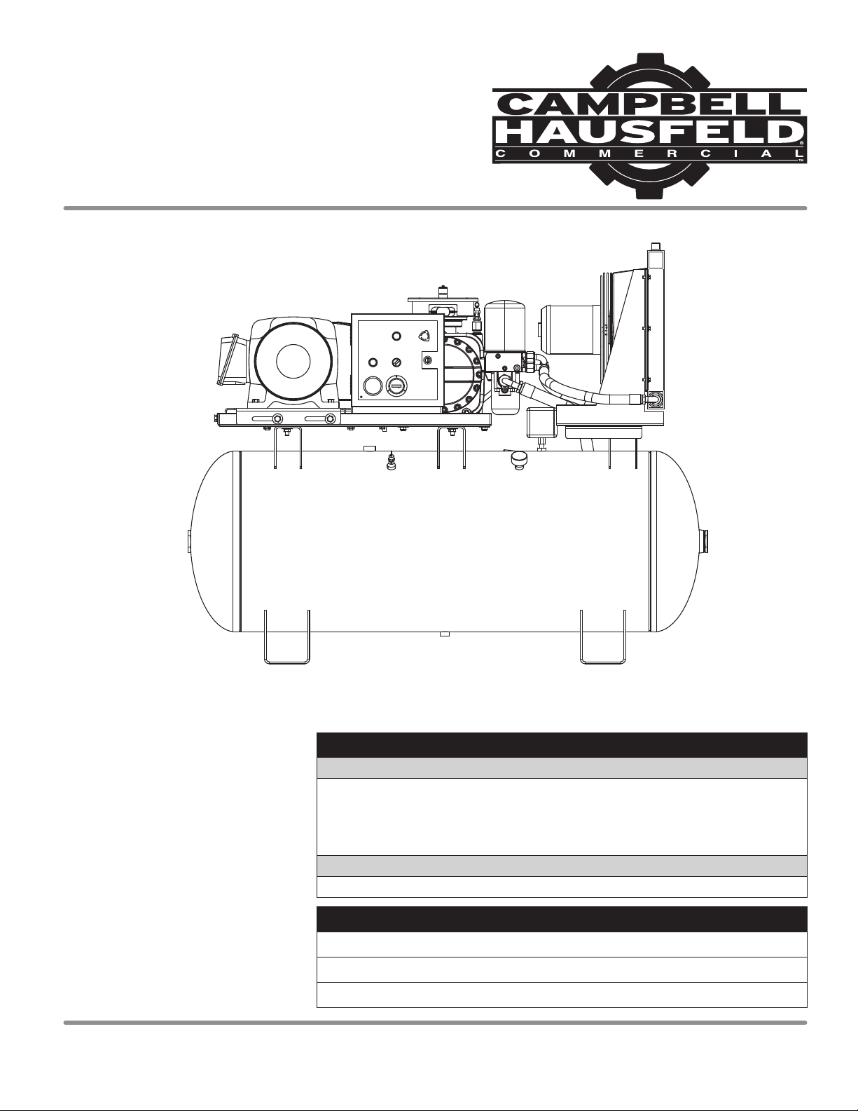
Operating Instructions
Rotary Screw
Air Compressors
Series CS Rotary Screw Compressors
Table of Contents
Safety Guidelines. . . . . . . . . . . . . . . . . . . . . 2
Safety Symbols . . . . . . . . . . . . . . . . . . . . . . . 2
Important Safety Information . . . . . . . . . 2
Specifications . . . . . . . . . . . . . . . . . . . . . . . . 2
Getting To Know Your Compressor . . . . 4
Unpacking. . . . . . . . . . . . . . . . . . . . . . . . . . . 7
Installation . . . . . . . . . . . . . . . . . . . . . . . . . . 7
Wiring Diagram . . . . . . . . . . . . . . . . . . . . . . 9
Operation . . . . . . . . . . . . . . . . . . . . . . . . . . 13
Maintenance. . . . . . . . . . . . . . . . . . . . . . . . 14
Troubleshooting Guide . . . . . . . . . . . . . . 18
Limited Warranty. . . . . . . . . . . . . . . . . . . . 20
Quick Reference
OIL
Single viscosity ISO100 rotary screw compressor oil
(Part number GS903800AV - 1 Gallon Container).
Available from Campbell Hausfeld, please call 1-855-504-5678 for customer
assistance.
OIL CAPACITY
2.1 gallons
RETAIN THIS INFORMATION FOR FUTURE REFERENCE
Serial Number:
Model Number:
Date of Purchase:
IN564600AV 10/12© 2012 Campbell Hausfeld/Scott Fetzer For parts, product & service information
visit www.campbellhausfeld.com
1-855-504-5678
Page 2
Operating Instructions
Please read and save these instructions. Read carefully before attempting to assemble, install,
Safety Guidelines
This manual contains information
that is very important to know and
understand. This information is
provided for SAFETY and to PREVENT
EQUIPMENT PROBLEMS. To help
operate or maintain the product described. Protect yourself and others by observing all safety
information. Failure to comply with instructions could result in personal injury and/or
property damage! Retain instructions for future reference.
Important Safety Information
This manual contains important safety, operational and maintenance information. If
you have any questions, please call 1-855-504-5678 for customer assistance.
recognize this information, observe
the following symbols.
Danger indicates
an imminently
hazardous situation which, if not avoided,
WILL result in death or serious injury.
Warning indicates
a potentially
hazardous situation which, if not avoided,
COULD result in death or serious injury.
Caution indicates
a potentially
hazardous situation which, if not avoided,
MAY result in minor or moderate injury.
Notice indicates
important
information, that if not followed, may cause
damage to equipment.
IMPORTANT: Information that
requires special attention.
CALIFORNIA PROPOSITION 65
This product or its power cord may contain chemicals known to the State
harm. Wash hands after handling.
You can create dust when you cut, sand, drill or grind
other masonry. This dust often contains chemicals known to cause cancer, birth
defects, or other reproductive harm. Wear protective gear.
This compressor/pump is not equipped and should not be used “as is” to supply
breathing quality air. For any application of air for human consumption, the air
compressor/pump will need to be fitted with suitable in-line safety and alarm
equipment. This additional equipment is necessary to properly filter and purify
the air to meet minimal specifications for Grade D breathing as described in
Compressed Gas Association Commodity Specification G 7.1, OSHA 29 CFR 1910.
134, and/or Canadian Standards Associations (CSA).
Safety Symbols
The following Safety Symbols appear
throughout this manual to alert you
to important safety hazards and
precautions.
DISCLAIMER OF WARRANTIES
In the event the compressor is used for the purpose of breathing air application
and proper in-line safety and alarm equipment is not simultaneously used,
existing warranties shall be voided, and Campbell Hausfeld disclaims any
liability whatsoever for any loss, personal injury or damage.
of California to cause cancer and birth defects or other reproductive
materials such as wood, paint, metal, concrete, cement, or
Breathable Air Warning
Wear Eye
and Mask
Protection
Risk of
Moving Parts
Risk of
Fumes
www.campbellhausfeld.com
2
MANUAL
Read Manual
First
Risk of
Hot Parts
Risk of
Pressure
Risk of
Fire
Risk of
Explosion
Risk of
Electrocution
Specifications
Air Delivery @ 150 psi
Model HP Voltage Phase
CS2152 15 208 3 46 CFM 120
CS2153 15 230 3 46 CFM 120
CS2154 15 460 3 46 CFM 120
CS2202 20 208 3 68 CFM 120
CS2203 20 230 3 68 CFM 120
CS2204 20 460 3 68 CFM 120
CS2252 25 208 3 87 CFM 120
CS2253 25 208 3 87 CFM 120
CS2254 25 460 3 87 CFM 120
Operating Pressure Tank Size (Gallons)
Page 3
Important Safety Information (Continued)
Series CS Rotary Screw Compressors
GENERAL SAFETY
◆ Read all manuals included with this product
carefully. Be thoroughly familiar with the controls
MANUAL
and the proper use of the equipment.
◆ Follow all local electrical and safety codes as well as
the United States National Electrical Codes (NEC) and
Occupational Safety and Health Act (OSHA).
◆ Only persons well acquainted with these rules of safe
operation should be allowed to use the compressor.
◆ Keep visitors away and NEVER allow children in the work
area.
◆ Wear safety glasses and use hearing protection when
operating the unit.
◆ Do not stand on or use the unit as a handhold.
◆ The protection devices fitted to this compressor are provided
to offer safety of operation. The operator is solely responsible
for personal safety at all times.
These devices should not be adjusted except by an authorised
service agent.
◆ Before each use, inspect compressed air system and electrical
components for signs of damage, deterioration, weakness or
leakage. Repair or replace defective items before using.
◆ Check all fasteners at frequent intervals for proper tightness.
Motors, electrical equipment
and controls can cause electrical
arcs that will ignite a fl ammable gas or vapor. Never
operate or repair in or near a fl ammable gas or vapor.
Never store fl ammable liquids or gases in the vicinity of the
compressor.
Never operate compressor without
a beltguard. This unit can start
automatically without warning. Personal injury or
property damage could occur from contact with moving
parts.
◆ Do not wear loose clothing or jewelry that will get caught in
the moving parts of the unit.
Compressor parts may be hot even if
the unit is stopped.
◆ Keep fingers away from a running compressor;
fast moving and hot parts will cause injury and/or
burns.
◆ If the equipment should start to vibrate abnormally, STOP
the engine/motor and check immediately for the cause.
Vibration is generally an indication of trouble.
◆ To reduce fire hazard, keep engine/motor exterior free of oil,
solvent, or excessive grease.
An ASME code safety relief valve with a setting
no higher than the Maximum Allowable
Working Pressure (MAWP) of the tank MUST be installed in the air
lines or in the tank for this compressor. The ASME safety valve must
have suffi cient fl ow and pressure ratings to protect the pressurized
components from bursting. The fl ow rating can be found in the parts
manual. The safety valve in the intercooler does not provide system
protection.
Maximum operating pressure is 150 psi. Do not
operate with pressure switch or pilot valves set
higher than the factory setting.
◆ Never attempt to adjust ASME safety valve. Keep safety valve
free from paint and other accumulations.
Never attempt to repair or modify
a tank! Welding, drilling or any
other modifi cation will weaken the tank resulting in
damage from rupture or explosion. Always replace worn,
cracked or damaged tanks.
Drain liquid from tank daily.
◆ Tanks rust from moisture build-up, which weakens the tank.
Make sure to drain tank regularly and inspect periodically for
unsafe conditions such as rust formation and corrosion.
◆ Fast moving air will stir up dust and debris which may be
harmful. Release air slowly when draining moisture or
depressurizing the compressor system.
SPRAYING PRECAUTIONS
Do not spray fl ammable materials
in vicinity of open fl ame or near
ignition sources including the compressor unit.
◆ Do not smoke when spraying paint, insecticides,
or other flammable substances.
◆ Use a face mask/respirator when spraying and
spray in a well ventilated area to prevent health
and fire hazards.
◆ Do not direct paint or other sprayed material
at the compressor. Locate compressor as far away from
the spraying area as possible to minimize overspray
accumulation on the compressor.
◆ When spraying or cleaning with solvents or toxic
chemicals, follow the instructions provided by the chemical
manufacturer.
SAVE THESE INSTRUCTIONS
DO NOT DISCARD
The DANGER, WARNING, CAUTION, and NOTICE
notifications and instructions in this manual cannot cover
all possible conditions and situations that may occur.
It must be understood by the operator that caution is a
factor which cannot be built into this product, but must be
supplied by the operator.
www.campbellhausfeld.com
3
Page 4
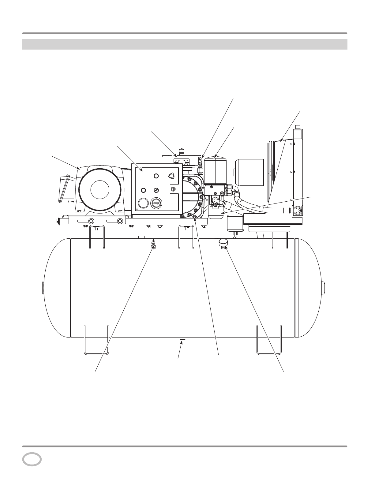
Operating Instructions
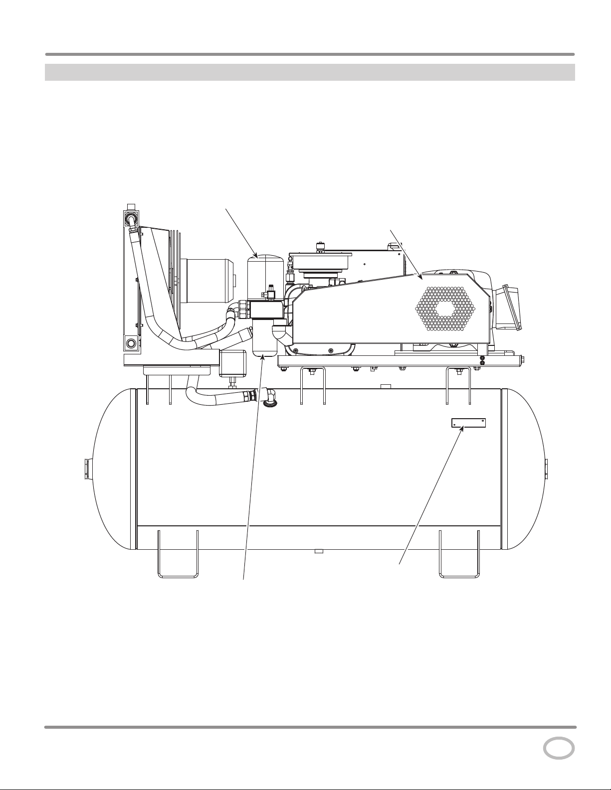
Getting To Know Your Compressor
Control Box
Motor
Air End Safety
Valve
Oil Cooler
Assembly
Air / Oil
Separator
Air End
Oil
Filter
Tank Safety Valve
Figure 1 - Components of the compressor
www.campbellhausfeld.com
4
Tank Drain
Oil
Drain
Tank Pressure
Gauge
Page 5
Getting To Know Your Compressor
Air / Oil
Separator
Series CS Rotary Screw Compressors
Beltguard
Figure 2 - Components of the compressor
Oil Filter
ASME Label
www.campbellhausfeld.com
5
Page 6
Operating Instructions
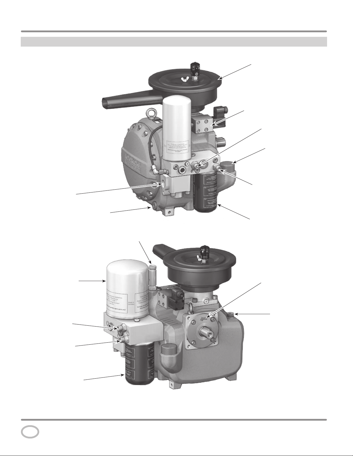
Getting To Know Your Compressor
Air Intake / Filter Assembly
Electric Control Unit
Oil Circulation
Connection / Outlet
Oil Fill Opening and Cap
Compressed
Air Outlet
Air / Oil Separating
Element
Oil Circulation
Connection / Outlet
Oil Circulation
Connection / Inlet
Oil Circulation
Connection / Inlet
Oil Drain Screw
Oil Filter
Safety Valve
Rotation Direction
Preset
Temperature Sensor
Connection
Oil Filter
Figure 3 - Components of the air end
www.campbellhausfeld.com
6
Page 7
Series CS Rotary Screw Compressors
Unpacking
Do not lift or move unit without appropriately rated equipment. Be sure the unit is securely attached to lifting device used.
Do not lift unit by holding onto tubes or coolers. Do not use unit to lift other attached equipment.
After unpacking the unit, inspect carefully for any damage that may have occurred during transit. Check for loose, missing or
damaged parts. Check to be sure all supplied accessories are enclosed with the unit. In case of questions, damaged or missing parts,
please call 1-855-504-5678 for customer assistance.
Do not operate unit if damaged during shipping, handling or use. Damage may result in bursting and cause injury
or property damage.
Installation
Disconnect, tag and lock out power
source then release all pressure from the
system before attempting to install, service, relocate or perform
any maintenance.
Do not lift or move unit without appropriately
attached to lifting device used. Do not lift unit by holding onto tubes or
coolers. Do not use unit to lift other attached equipment.
Never use the wood shipping skids for mounting
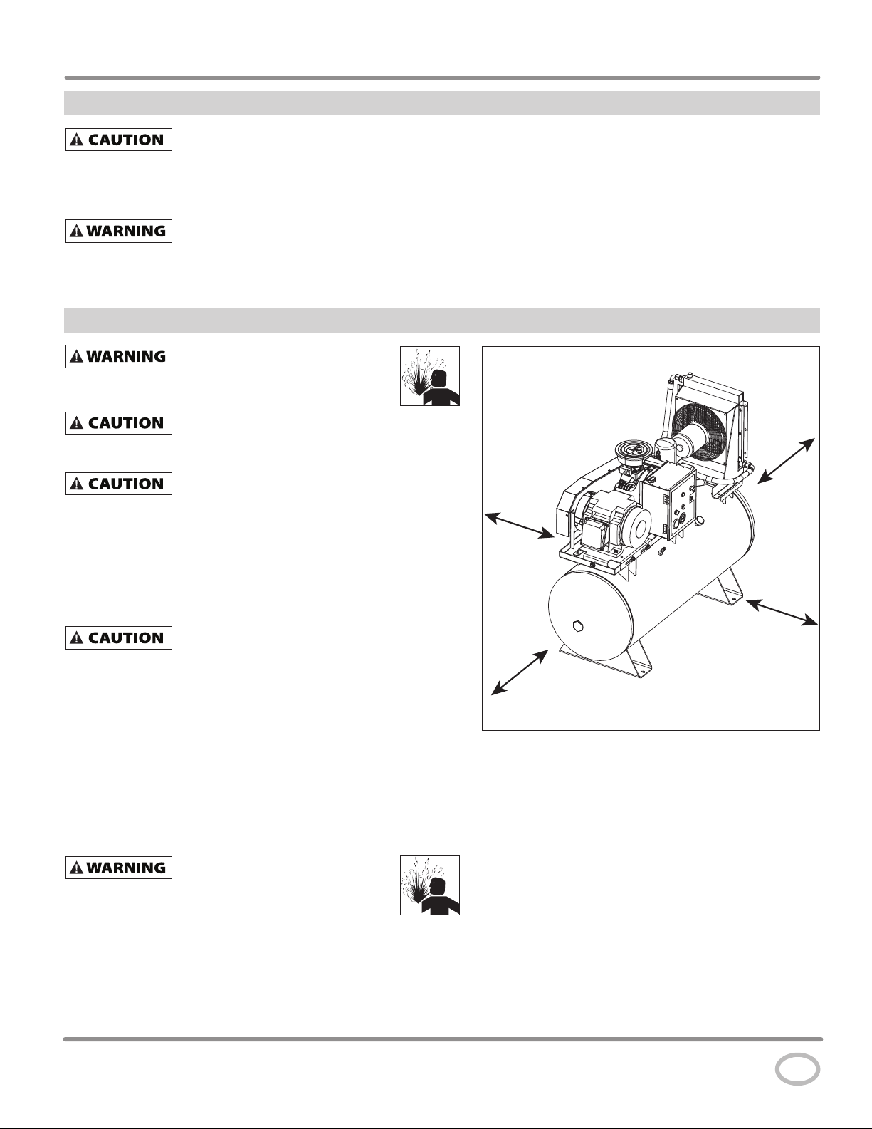
PICKING THE LOCATION
Install and operate unit at least 36 inches from any obstructions in a
clean, ventilated area. The surrounding air temperature should not
exceed 100° F or fall below 40° F. This will ensure an unobstructed
flow of air to cool compressor and allow adequate space for
maintenance.
Do not locate the compressor air inlet near
source of contamination.
NOTE: If compressor operates in a hot, moist environment, supply
compressor pump with clean, dry outside air. Supply air should be
piped in from external sources.
TANK MOUNTING
The tank should be bolted into a flat, even, concrete floor or on a
separate concrete foundation.
If using isolator pads, do not draw bolts tight. Allow the pads
to absorb vibrations. When isolators are used, a flexible hose or
coupling should be installed between the tank and service piping.
Failure to properly install the tank can
possible bursting.
rated equipment. Be sure the unit is securely
the compressor.
steam, paint spray, sandblast areas or any other
lead to cracks at the welded joints and
36 inches
36 inches
36 inches
36 inches
Figure 4 - Location
www.campbellhausfeld.com
7
Page 8
Operating Instructions
Installation (Continued)
PIPING
Never use plastic (PVC) pipe for compressed air.
Serious injury or death could result.
Any tube, pipe or hose connected to the unit must be able to
withstand the temperature generated and retain the pressure. All
pressurized components of the air system must have a pressure
rating of 200 psi or higher. Incorrect selection and installation
of any tube, pipe or hose could result in bursting and injury.
Connect piping system to tank using the same size fitting as the
discharge port.
INSTALLING A SHUT-OFF VALVE
A shut-off valve should be installed on the discharge port of the
tank to control the air flow out of the tank. The valve should be
located between the tank and the piping system.
Never install a shut-off valve between the
compressor pump and the tank. Personal injury
and/or equipment damage may occur. Never use reducers in discharge
piping.
When creating a permanently installed system to distribute
compressed air, find the total length of the system and select
pipe size from the chart. Bury underground lines below the
frost line and avoid pockets where condensation can gather and
freeze.
Apply air pressure to the piping installation and make sure
all joints are free from leaks BEFORE underground lines are
covered. Before putting the compressor into service, find and
repair all leaks in the piping, fittings and connections.
WIRING (see page 9 for wiring diagrams)
All wiring and electrical connections must be
performed by a qualifi ed electrician familiar
with induction motor controls. Installations must be in accordance
with local and national codes.
Overheating, short circuiting and fi re damage
will result from inadequate wiring.
Wiring must be installed in accordance with National Electrical
Code and local codes and standards that have been set up
covering electrical apparatus and wiring. These should be
consulted and local ordinances observed. Be certain that
adequate wire sizes are used, and that:
1. Service is of adequate ampere rating.
2. The supply line has the same electrical characteristics
(voltage, cycles and phase) as the motor. Refer to motor
name plate for electrical ratings and specifications.
3. The line wire is the proper size and that no other equipment
is operated from the same line. The chart gives minimum
recommended wire sizes for compressor installations.
MINIMUM PIPE SIZE FOR COMPRESSED AIR LINE
Length Of Piping System
CFM
25 feet 50 feet 100 feet 250 feet
10 1/2 inch 1/2 inch 3/4 inch 3/4 inch
20 3/4 inch 3/4 inch 3/4 inch 1 inch
40 3/4 inch 1 inch 1 inch 1 inch
60 3/4 inch 1 inch 1 inch 1 inch
100 1 inch 1 inch 1 inch 1-1/4 inch
Figure 5 - Shut-off Valve
MINIMUM WIRE SIZE
(USE A MINIMUM OF 75°C COPPER WIRE)
Make sure voltage is correct with the motor wiring.
NOTE: If using 208 volts single phase, make sure the motor
name plate states it is rated for 208 volts single phase. 230 volt
single phase motors do not work on 208 volts unless they have
the 208 volt rating.
Three Phase
HP 208/230V 460/575V
5 12 AWG 14 AWG
7.5 10 AWG 12 AWG
10 8 AWG 12 AWG
15 6 AWG 10 AWG
20 3 AWG 8 AWG
25 3 AWG 8 AWG
Recommended wire sizes may be larger than the minimum set up by
local ordinances. If so, the larger size wire should be used to prevent
excessive line voltage drop. The additional wire cost is very small
compared with the cost of repairing or replacing a motor electrically
“starved” by the use of supply wires which are too small.
www.campbellhausfeld.com
8
Page 9
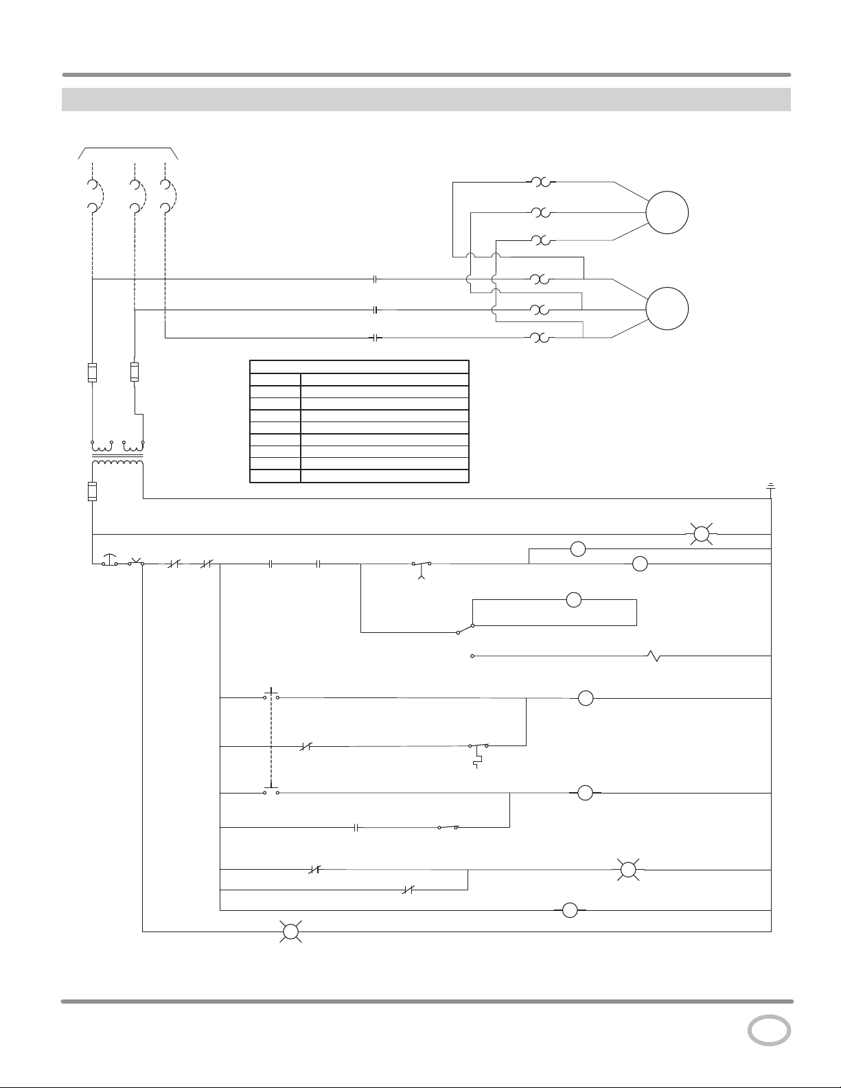
Wiring Diagram
TO SUPPLY
L1
L2 L3
Series CS Rotary Screw Compressors
OL
OL
OL
T4
T5
T6
M1
FAN
MOTOR
ESTOP
OFF
M
L1
M
L2
M
L3
OL
OL
OL
T1
T2
M2
T3
COMP
MOTOR
LEGEND
CT CONTROL TRANSFORMER
COL COIL OVERLOAD
FOL FAN OVERLOAD
HATR HIGH AIR TEMPERATURE RELAY
HPR HIGH PRESSURE RELAY
TR TIMER RELAY
TPS SWITCH, TANK PRESSURE
CT
ON
COL
FOL
M CONTACTOR-MAIN
HPS SWITCH, HIGH PRESSURE
HATR 1
HPR 1
POWER ON
HOUR
TR
TPs
5
METER
TR
M
7
INLET
VALVE
w
RESET
G
HATR 2
9
HATR 3
HATR
13
14
HATS
24
5
HPR 2
HPR 3
HPS
26
HPR
R
TR
www.campbellhausfeld.com
9
Page 10
Operating Instructions
Installation (Continued)
GROUNDING
Improperly grounded electrical
components are shock hazards.
Make sure all the components are properly grounded to
prevent death or serious injury.
This product must be grounded. Grounding reduces
the risk of electrical shock by providing an escape wire for the
electric current if short circuit occurs. This product must be
installed and operated with a cable that has a grounding wire.
BREAKERS AND FUSES
The entire electrical system should be checked by a certified
electrician. Time delay breakers and fuses are required for this
compressor. A tripped breaker or blown fuses may indicate a
direct short to ground, high current draw, improper wiring,
incorrect fuse or breaker size and/or type. This needs to be
evaluated by a certified electrician.
MOTOR HOOKUP AND STARTER INSTALLATION
Branch circuit protection must be provided as specified in
the United States National Electrical Code, Chapter 2, “Wiring
Design and Protection.” Article 210, using the applicable article
“For Motors and Motor Controllers,” (Article 430,
Table 430-1 52).
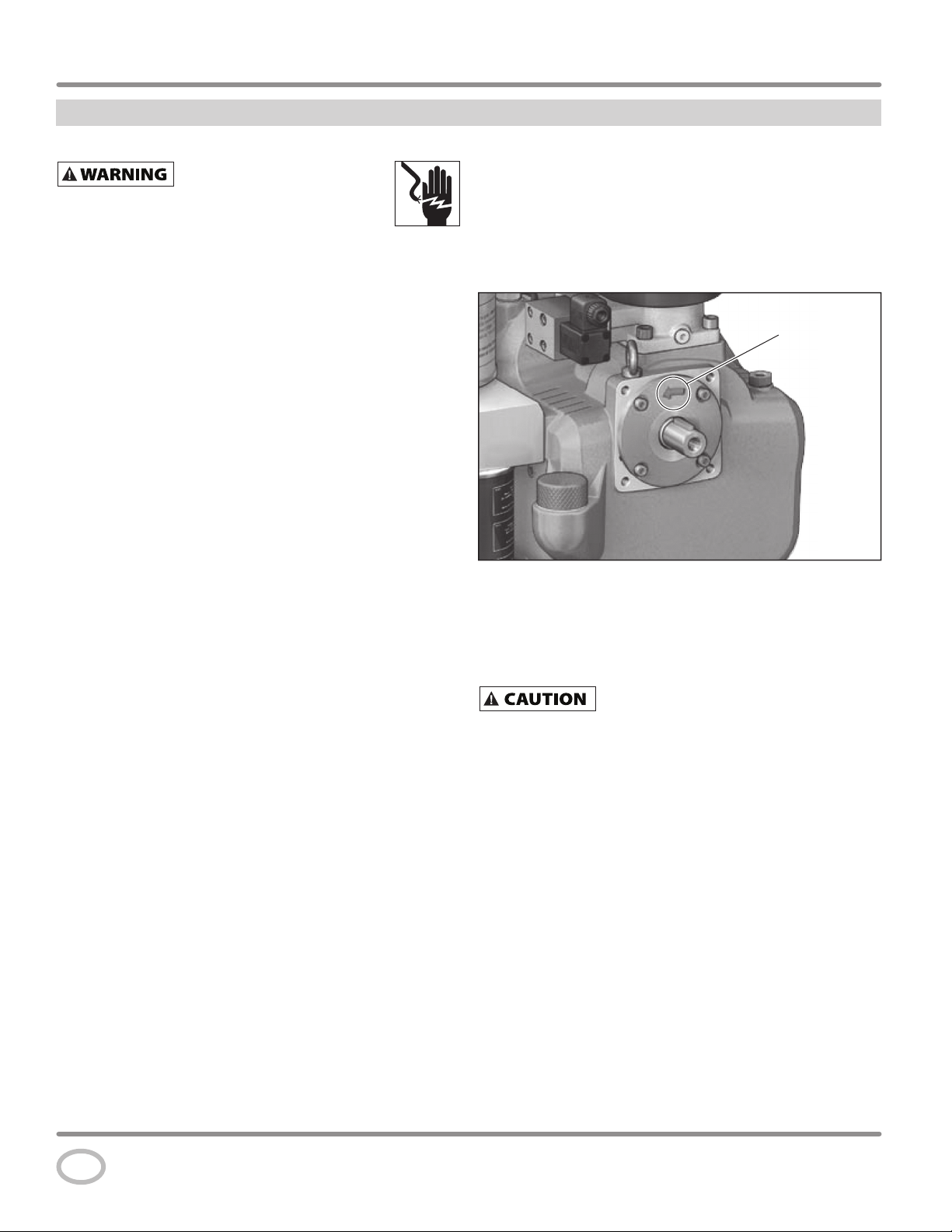
DIRECTION OF ROTATION
NOTE: Improper rotation will result in failure or compressor.
The direction of rotation must be counterclockwise (as shown
by the arrow on the air end in Figure 6) while facing the flywheel
side of the pump.
The direction of rotation of 3 phase motors can be reversed by
interchanging any two motor-line leads.
Rotation
Figure 6 - Direction of rotation
CHECKING ROTATION DIRECTION
ROTATION DIRECTION: rotating to the left (counterclockwise)
looking at the shaft.
The rotation direction of the screw compressor
system must be checked during initial start-up
and each time changes are made to the electrical supply line of the
electric motor drive. For this purpose, switch on the drive motor briefl y
and then switch off again immediately. ROTATION FOR MORE THAN
2 SECONDS IN THE WRONG ROTATION DIRECTION WILL DESTROY
THE SCREW COMPRESSOR. If necessary, reverse the connections of the
connecting cable.
www.campbellhausfeld.com
10
Page 11
Installation (Continued)
LUBRICATION
THIS UNIT CONTAINS OIL. Before operating
compressor, check oil level (see Figure 7).
Using any other type of oil may shorten pump
life and result in damage.
Recommended Oil
Single viscosity ISO100 rotary screw compressor oil (Part
number GS903800AV - 1 Gallon Container). Available from
Campbell Hausfeld, please call 1-855-504-5678 for customer
assistance.
Oil Capacity
2.1 gallons
OIL LEVEL
Disconnect, tag and lock out
power source then release all
pressure from the system before attempting to install,
service, relocate or perform any maintenance.
RISK OF BURNS! The unit parts, oil,
and screw plug can be hotter than
175° F (80° C)! Wear personal safety equipment!
Series CS Rotary Screw Compressors
Oil Plug
Maximum
(cold oil level)
Minimum
(cold oil level)
Figure 7 - Oil Level
With hot oil, the oil level can be approximately
3/4 inch higher than with cold oil shortly after
discharging.
An important factor for the operating safety of the compressor
system is the oil level in the oil reservoir. The oil level check must
be performed before initial operation of the compressor and
then repeated every 100 operating hours.
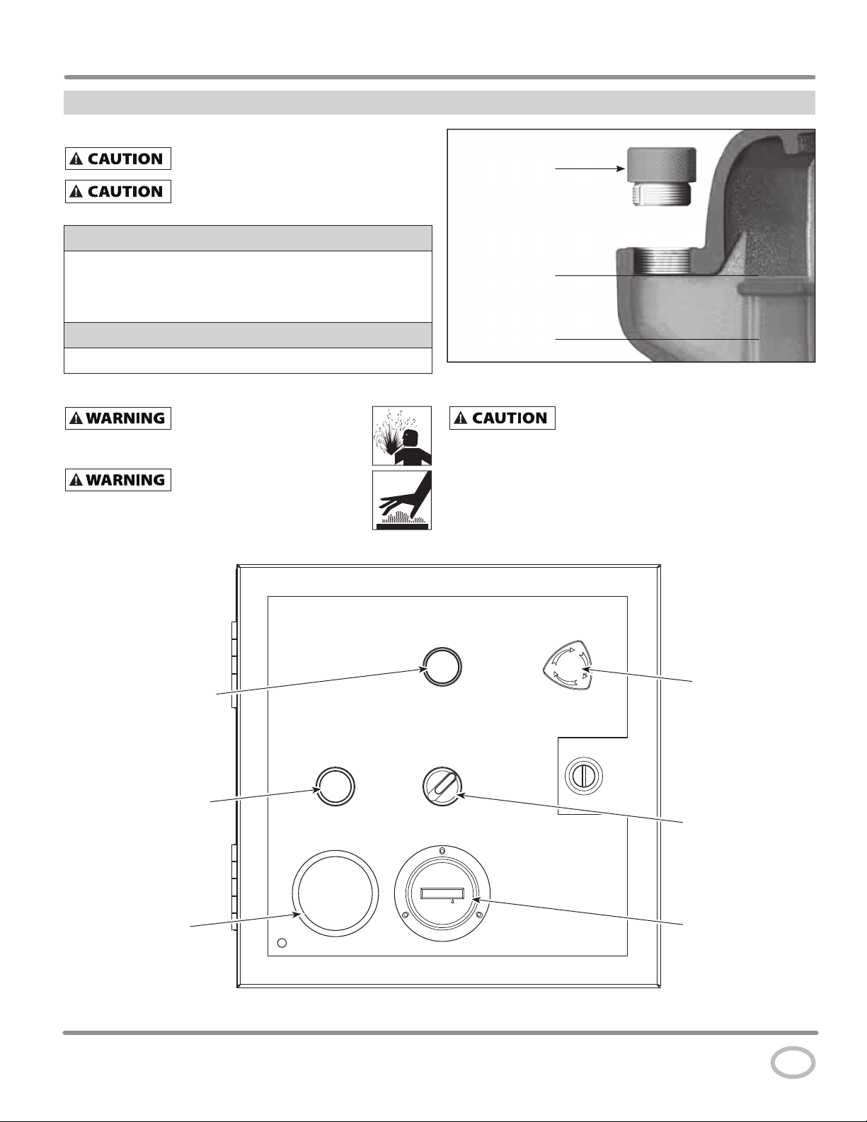
Power Indicator
(WHITE)
High Temperature /
High Pressure
Indicator Light
and Reset (RED)
Temperature
Gauge
Figure 8 - Control Panel
E-Stop
ON / OFF Switch
[Lighted when in
ON position (GREEN)]
Hour Meter
www.campbellhausfeld.com
11
Page 12
Operating InstructionsOperating Instructions
Prime Port
Pulley
Installation (Continued)
OIL LEVEL CHECK (See Figure 7)
• Check oil level by removing oil plug.
• With hot oil, the level will be higher than with cold oil.
As a result, oil may escape when the oil plug is opened at the
maximum oil level. If this does happen, close the oil plug
immediately and carefully clean up the oil that has escaped.
NOTE: The oil plug is provided with a safety hole on the side
from which oil or air escapes if there is any residual pressure
in the air end. Wait for one minute after the unit is at standstill
before opening the oil plug.
1. Switch off the system, prevent it from being switched back
on without authorization.
2. Wait for one minute at standstill.
3. Unscrew the oil plug on the filler neck by hand with the air
end depressurized.
4. Check the oil level.
5. If necessary, top off oil of the same oil type and the same
brand up to the maximum level (see Figure 7 and Lubrication
section).
NOTE: The oil filler neck is positioned so that it is not possible to
overfill the system. Excess oil runs out of the filler neck.
6. Screw on the oil plug firmly by hand.
7. Switch on the system.
8. Wipe off and clean up any spilled oil.
START-UP INFORMATION
READ AND UNDERSTAND ALL STEPS BELOW
BEFORE TURNING ON POWER .
1. Check oil level (See Figure 7).
2. If it has been longer than 12 weeks since the compressor has
been operated the air end must be primed with 8 ounces of
oil.
units must be checked for leaks and proper function. Loose
connections must be refastened and damaged lines must be
replaced.
Screw compressor systems that are switched off, shut down,
or stored for longer than 12 weeks cannot be placed into
operation again until after the following steps have been
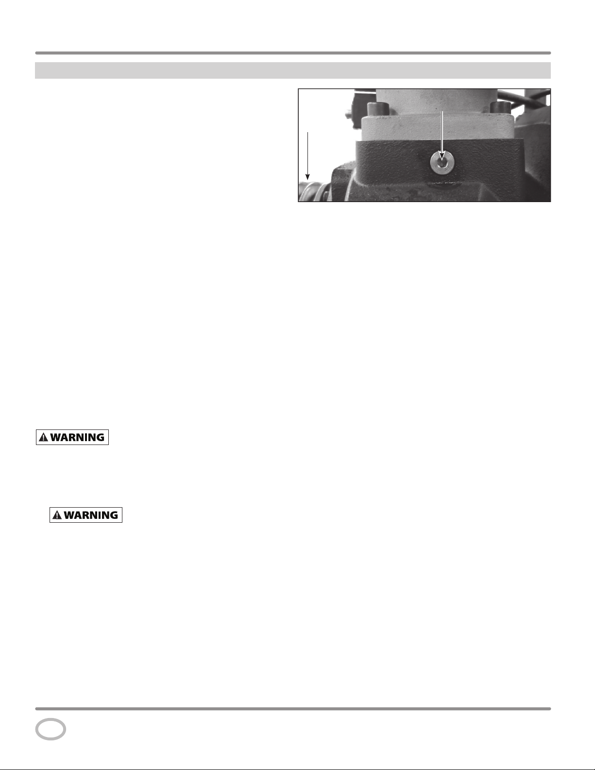
carried out:
a. Manually rotate the compact module screw compressor
in the rotation direction several times.
b. With the compressor system stopped, add approximately
8 ounces of oil (same oil type as in the air end) into the
rotor chamber (see Figure 9).
c. Once again, manually rotate the compressor module
compressor stage in the rotation direction several times.
Before resuming operation, the
electrical equipment and all safety-relevant
Prime Port
Pulley
Figure 9 - Air End Priming Location
d. Check the oil level in the air end and top off if necessary
(see Maintenance section).
e. Monitor operation of the compressor system for at least
15 minutes, but at least until the steadystate temperature
is reached (continuous operating temperature).
3. Direction of rotation must be checked. Operation of the
air end for more than 2 seconds in the wrong direction will
destroy the screw compressor.
4. Check direction of rotation by quickly bumping the power to
ON and having someone else watch the motor pulley to see
which way it turns. Belt guard should remain installed. Also
check the direction of rotation of the oil cooler fan. The fan
must suck air in from the wire guard side and push air out
through the radiator when turning the correct direction. This
can be checked by holding a small strip of paper in front of
the radiator. With the correct direction of rotation the paper
will blow out away from the radiator.
5. Reset E-Stop switch if needed (see Figure 8).
6. Turn on the incoming power at the disconnect switch/circuit
breaker. The White incoming power indicator lamp will
illuminate. The motor will not turn on with this step.
7. Turn the on/off switch to the On position. The green lamp
will illuminate indication the compressor is ready to run.
The RED High temperature/High Pressure Failure Lamp will
illuminate. The motor will not turn on with this step.
8. Keep your hand on the on/off switch ready to turn off
immediately after start up to check the rotation direction.
Also check the direction of the cooler fan.
9. The motor can now be started by pressing the High temp/
high pressure reset. The red lamp is also a momentary
contact switch. The motor will start with this step.
10. Immediately turn off the on/off switch. The motor will stop
with this step.
11. If the direction of rotation is incorrect, disconnect, lock out
and tag out all incoming power. Change the position of two
of the incoming power lines and repeat steps 5-10.
12. When the direction of rotation has been confirmed the
compressor is ready to run for an initial start up operation
check.
www.campbellhausfeld.com
12
Page 13

Operation
INITIAL OPERATION CHECK
IMPORTANT: Check motor rotation before operating the
compressor.
After confirming the correct direction of rotation for the main
motor and cooler fan, the compressor is ready to run for an
operation check.
With a valve installed at the outlet of the tank, close the valve
and isolate the tank from any pipeline system so only the
compressor tank will fill up with compressed air.
1. Turning the compressor on. Confirm position of E-stop.
White incoming power lamp (Power Indicator) should be on.
2. Turn the ON / OFF switch to the ON position. The green light
of the switch should be on. The compressor will start. If the
red high temperature / high pressure light is on, press it to
reset and the compressor will start.
3. Allow the compressor to run for approximately 5 minutes.
The pressure in the tank will rise as the compressor runs.
The following will take place:
a. When first turned on the air end will build up internal
pressure prior to sending air into the tank. This may take
15-20 seconds. You may notice a slight change in the
sound when the minimum pressure valve opens inside
the air end allowing air to flow into the tank.
b. Air pressure in the tank will rise until the pre-set
maximum pressure is reached. Upon reaching the
maximum pressure the compressor will switch to the
Unloaded Mode. The noise level will change to be quieter.
Air is no longer being pumped into the tank. The air
intake valve is now closed inside the air filter housing.
High pressure air from inside of the compressor housing
is vented slowly (Lasts about 1 minute) out through the
air filter housing to allowing the compressor to run at
idle. You may hear the high pressure air being vented for
about 1 minute. You may see a small amount of oil smoke
coming from the inlet. This is normal as a small amount
of oil may be released with the high pressure air.
Do not remove air fi lter housing or
perform any maintenance with pressure
in the air end or air pressure tank.
c. While the compressor is running look and listen for any
leaks with which may have developed during shipping
and handling.
RISK OF BURNS! Surfaces
and parts will become hot.
4. Allow compressor to run for approximately 5 minutes. Turn
off using the ON / OFF switch. Allow compressor to sit for at
least 1 minute while the high pressure air is released through
the compressor inlet. You will hear the air escaping.
Disconnect, tag and lock out
power source then release all
pressure from the system before attempting to install,
service, relocate or perform any maintenance.
5. Release all air pressure from the tank prior to performing any
maintenance or restarting the compressor for the next run
sequence in item #8.
6. Allow the compressor to cool, and then check the oil level.
Add oil if needed.
7. Seal any air or oil leaks if needed.
8. Restart air compressor. Check position of E-Stop. Turn
on main power. Turn ON / OFF switch to ON. Reset high
temperature / high pressure switch and the compressor will
start.
9. With valve at the tank outlet closed the air pressure will build
in the tank to the cut-out pressure. Air pressure in the tank
will rise until the pre-set maximum pressure is reached.
Upon reaching the maximum pressure the compressor will
switch to the Unloaded Mode. The noise level will change to
be quieter. Air is no longer being pumped into the tank. The
air intake valve is closed inside the air filter housing. High
pressure air from inside of the compressor housing is vented
slowly out through the air filter housing to allowing the
compressor to run at idle. You may hear the high pressure air
being vented for about 1 minute.
10. Inside the electrical box, the idle delay timer begins tracking
time. After approximately 15 minutes of operation at idle the
compressor will turn off.
11. Release pressure from the tank down to the cut-in pressure
and the compressor will automatically restart. Pressure
will build in the tank until the cut-out pressure and go into
unloaded mode again. Wait approximately 1 minute and
then release some air from the air tank.
When the pressure in the tank drops to the cut-in pressure the
air inlet valve will open allowing the air to be compressed and
re-fill the tank. The idle delay timer will reset for the next cycle.
This sequence of operation will continue until the ON/OFF
switch is turned to the off position.
Your compressor is now ready for use.
NOTE: All lubricated compressor pumps discharge some
condensed water and oil with the compressed air. Install
appropriate water/oil removal equipment and controls as
necessary for the intended application.
www.campbellhausfeld.com
13
Page 14

Operating Instructions
Operation (Continued)
Failure to install appropriate water / oil
removal equipment may result in damage to
machinery or workpiece.
AMBIENT OPERATING TEMPERATURE
The compressor is designed to operate in an ambient
temperature between 40° F and 100° F. At ambient temperatures
below 40° F, the unit must be heated up to at least 70° F before
start-up.
GUARDING
The belt guard provided must be
Never operate compressor without
automatically without warning. Personal injury or
property damage could occur from contact with moving parts.
All moving parts must be guarded. All electrical covers must be
installed before turning on the power.
DRAINING TANK
Condensate must be drained from the tank daily.
Maintenance
See Maintenance Schedule on Page 17.
Disconnect, tag and lock out power source then release all
pressure from the system before attempting to install, service,
relocate or perform any maintenance.
In order to maintain efficient operation of the compressor system, check the
air filter and oil level before each use. The ASME safety valve should also be
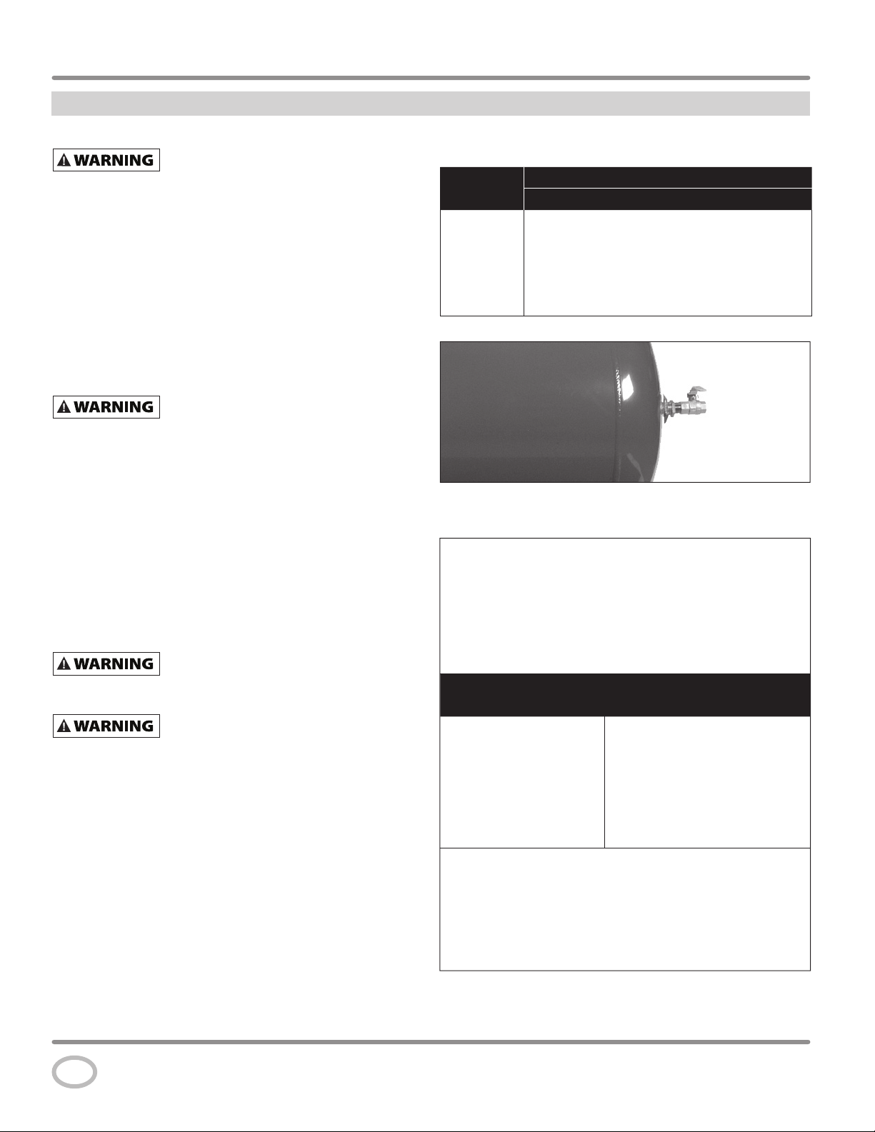
checked daily (see Figure 10). Pull ring on safety valve and allow the ring to snap back
to normal position. This valve automatically releases air if the tank pressure exceeds
the preset maximum. If air leaks after the ring has been released, or the valve is stuck
and cannot be actuated by the ring, the ASME safety valve must be replaced.
installed on the unit.
a beltguard. This unit can start
Figure 10 - ASME Safety Valve
Do not tamper with the ASME safety valve.
TANK
Never attempt to repair or modify a tank! Welding, drilling or
any other modifi cation will weaken the tank resulting in
damage from rupture or explosion. Always replace worn, cracked or damaged
tanks.
Drain liquid from tank daily.
The tank should be carefully inspected at a minimum of once a year. Look for cracks
forming near the welds. If a crack is detected, remove pressure from tank immediately
and replace.
www.campbellhausfeld.com
14
Page 15

Maintenance (Continued)
Series CS Rotary Screw Compressors
OIL CHANGE
RISK OF INJURY! The unit consists of rotating
and pressurized components. Do not attempt
to change oil until the unit has completely stopped and been fully
depressurized.
Disconnect, tag and lock out
power source then release all
pressure from the system before attempting to install,
service, relocate or perform any maintenance.
RISK OF BURNS! The unit parts, oil,
and screw plug can be hotter than
175° F (80° C)! Wear personal safety equipment!
1. Switch off the system, prevent it from being
switched back on without authorization, and
bring it into a horizontal position.
2. Depressurize the tank and system completely..
3. Unscrew the oil plug of the filler neck by hand.
4. Carefully unscrew the oil drain cap and catch the used oil in
a suitable container.
Dispose of the used oil, oil-contaminated
container, and cloths in accordance with local
regulations.
5. Clean the oil drain screw to remove any remaining oil.
Tighten drain cap to original closed position.
3. Remove the oil filter cartridge with a suitable tool, e.g. oil
filter strap wrench.
Dispose of the old oil fi lter cartridge in
accordance with the applicable regulations.
4. Oil the seal on the new oil filter cartridge with oil of the same
oil type as in the air end.
5. The new oil filter cartridge must be held vertically and filled
with oil of the same oil type as in the compressor module
before being screwed on.
6. Screw the new oil filter cartridge onto the multiblock and
tighten by hand. No tool is required.
7. Switch on the system.
8. The oil filter must then be checked for leaks with the system
running.
9. Check the oil level as explained earlier and top up the
missing oil quantity again to the maximum level.
Oil Drain Pipe and Cap
Figure 11 - Oil Drain
OIL FILTER
RISK OF INJURY! The unit consists of rotating
and pressurized components. Do not attempt
to change oil until the unit has completely stopped and been fully
depressurized.
RISK OF BURNS! The unit parts, oil,
and screw plug can be hotter than
175° F (80° C)! Wear personal safety equipment!
NOTE: Replace the oil filter with every oil change.
1. Switch off the screw compressor system and prevent it from
being switched back on without authorization.
2. Depressurize the system completely.
Oil Filter
Multiblock
Filter Seal
Figure 12 - Oil Filter
AIR-OIL SEPARATING ELEMENT
RISK OF INJURY! The unit consists of rotating
and pressurized components. Do not attempt
to change oil until the unit has completely stopped and been fully
depressurized.
RISK OF BURNS! The unit parts, oil,
and screw plug can be hotter than
175° F (80° C)! Wear personal safety equipment!
Heavily soiled intake air or low-
quality oil cause heavier soiling of
the cartridge, which can result in the premature need for replacement.
1. Switch off the screw compressor system and prevent it from
being switched back on without authorization.
2. Unscrew the air-oil separating element with a suitable tool,
e.g. oil filter strap wrench.
Dispose of the used oil, oil-contaminated
container, and cloths in accordance with local
regulations.
www.campbellhausfeld.com
15
Page 16

Operating Instructions
Maintenance (Continued)
3. Oil the seal on the new air-oil separating element with
oil of the same oil type as in the compact module screw
compressor.
4. Tighten the new air-oil separating element by hand. No tool
is required.
5. Switch on the compressor system.
6. The air-oil separating element must be checked for leaks
with the system running.
Air-Oil
Separating
Elements
Figure 13 - Air-Oil Separating Element
FILLING WITH OIL
Make sure to use recommended oil. Add oil
of the same oil type from the same manufacturer.
Switching over to another oil type can require fl ushing of the screw
compressor.
NOTE: Replace the oil filter with every oil change.
1. Switch off the system, prevent it from being switched back
on without authorization.
2. Through the filler neck on the separating tank, add oil up
to the maximum level and reinsert the screw plug, turning
firmly onto the filler neck by hand.
3. Switch on the screw compressor and allow it to run for
approximately three minutes.
4. Switch off the system, prevent it from being switched back
on without authorization.
6. Top off the oil to the maximum level.
7. Switch on the screw compressor and return to normal use.
AIR INTAKE FILTER
Do not remove air fi lter housing or perform any
maintenance with pressure in the air end or air
pressure tank.
Never run the compressor pump without an intake air filter or
with a clogged intake air filter. The air filter element should be
checked monthly (see Figure 14). Operating compressor with
a dirty filter can cause high oil consumption and increase oil
contamination in the discharge air. If the air filter is dirty it must
be replaced.
In case of heavily soiled intake air, replace and check more
frequently.
Dirt and dust particles must not be permitted to
get into the air inlet of the compressor module.
Air intake must be clean and maintained.
It is not permissible to clean the fi lter element;
the fi lter element must always be replaced!
Dispose of the old air fi lter element according to local regulations.
1. Switch off the screw compressor system and prevent it from
being switched back on without authorization.
2. Screw off the wing nut and remove the filter cover.
3. Remove the old filter element.
4. Carefully remove dust from the filter housing.
5. Insert the new filter element in the filter housing.
6. Install the filter cover, ensuring proper positioning during
assembly.
7. Tighten the wing nut.
8. Switch on the system.
Wing Nut
Filter Cover
Filter Element
www.campbellhausfeld.com
16
Figure 14 - Air Intake Filter
OIL COOLER
Weekly, check the oil cooler to be sure all fittings are secure and
tight. Clean all dirt, dust and other accumulations.
Page 17

Series CS Rotary Screw Compressors
Maintenance (Continued)
COMPONENTS
Turn off all power and clean the air end, motor, fan blades, air lines, oil cooler and tank on a monthly basis.
BELTS
Lock out and tag the power then release all pressure from the tank to prevent unexpected movement of the unit.
Check belt tension every 3 months. Adjust belt tension to allow 3/8 inch deflection with normal thumb pressure. Also, align belts
using a straight edge against the face of the pulleys and touching the rim on both sides of the face. The belts should be parallel to this
straight edge.
Slots in the bed-plate allow for sliding the motor back and forth to adjust belt tension.
MAINTENANCE SCHEDULE
The following table provides an overview of the screw compressor maintenance based on operating hours.
Maintenance schedule (operating hours) Maintenance Work
Before starting 1. Check the oil level in the air end.
2. Prime air end if it has not been used for longer than 12 weeks.
Daily 1. Check the safety valves.
2. Drain tank to remove water.
3. Check belt tension.
At 50 operating hours 1. Check the oil level in the air end.
2. Tighten all screw pipe fittings and electrical screw terminal fittings; check all other
connections for firm seating.
Every 100 operating hours 1. Check oil level in the air end, top off if oil is low.
2. Listen for abnormal running noise during operation.
Immediately switch off the unit, locate the problem and have it fi xed.
An abnormal noise could indicate a potentially hazardous situation.
3. Check all lines, hoses, and screw fittings for leaks and externally visible damage.
RISK OF INJURY! Have leaks and damage repaired immediately!
It is not permissible to repair hydraulic hoses.
Every 2,000 operating hours or 1 year,
whichever comes first
Every 6 years with normal demand Replace hose lines.
1. Change the air-oil separating element.
2. Perform an oil change.
3. Replace oil filter.
4. Replace filter element in intake air filter.
5. Check system for leaks.
6. Clean the system.
7. Check belts (replace as needed).
8. Inspect hoses.
It is not permissible to repair hose lines. Hose lines MUST be replaced.
www.campbellhausfeld.com
17
Page 18

Operating Instructions
Troubleshooting Guide
SYMPTOM CAUSE SOLUTION
Unit fails to start - Motor
makes no noise
Unit starts but does not
get to full speed
Unit does not make any
or very little air
Unit runs very noisy Damage to the compressor Check to make sure the compressor has not been damaged in the
Oil smoke out of inlet on
shutdown
Insufficient power to
compressor
Source electric to the compressor is either the incorrect voltage,
insufficient wire size to carry the load, the fuse box or breaker box is not
sufficient to carry the load requirements to the compressor.
Unit wired incorrectly Any wiring other than what is stated in the manual could cause a
malfunction (see Wiring Section).
Wrong voltage supplied to
Make sure voltage is correct with the motor wiring (see Wiring Section).
unit
Loose electrical connections The entire electrical system should be checked by a certified electrician.
The incoming wires and the compressor electrical connections should
be checked. Loose connections will cause malfunctions.
Wrong size wiring Check that wire size is rated for the current of the compressor. State and
local codes vary widely and need to be checked before installation.
Blown fuse and / or tripped
breaker
The breaker and fuses required for this unit must be time delay.
A tripped breaker or blown fuse may result from a direct short to
ground, high current draw, improper wiring, incorrect fuse or breaker
size and/or type. This needs to be evaluated by a service center or
certified electrician.
Starter overload tripped Check and reset if necessary. If the overload trips after the initial reset,
refer to the section of the manual that covers this issue.
Insufficient power to
compressor
Source electric to the compressor is either the incorrect voltage,
insufficient wire size to carry the load, the fuse box or breaker box is not
sufficient to carry the load requirements to the compressor.
Loose electrical connections The entire electrical system should be checked by a certified electrician.
The incoming wires and the compressor electrical connections should
be checked. Loose connections will cause malfunctions.
Drain valve open Make sure the drain valve at the bottom of the tank is closed.
Air leak Check the entire system for leaks, including the compressor unit and
any piping attached to the compressor
Restricted or blocked intake Make sure that the air intake of the compressor is not blocked in any
way.
shipping or installation. Make sure the belt guard was not damaged.
Belt guard should not be making contact with flywheel or pulley.
Loose fasteners Check all bolts and nuts to assure they did not loosen during shipping.
Loose pulleys or belts Check to assure pulley and flywheel are correctly tightened.
Normal operation A small amount of oil may be released with the high pressure air that
vents through the air filter.
Do not remove air fi lter housing or perform any
maintenance with pressure in the air end or air
pressure tank.
www.campbellhausfeld.com
18
Page 19

Series CS Rotary Screw Compressors
Service Record
DATE MAINTENANCE PERFORMED REPLACEMENT COMPONENTS REQUIRED
www.campbellhausfeld.com
19
Page 20

Operating Instructions
REGISTER YOUR PRODUCT ONLINE NOW!
http://reg.ch-commercial.com
Limited Warranty
1. DURATION: From the date of purchase by the original purchaser as follows: Two years for the compressor air end. One year for
the balance of the compressor package.
2. WHO GIVES THIS WARRANTY (WARRANTOR): Campbell Hausfeld / Scott Fetzer Company, 100 Production Drive,
Harrison, Ohio, 45030, Telephone: (800) 543-6400.
3. WHO RECEIVES THIS WARRANTY (PURCHASER): The original purchaser (other than for purposes of resale) of the Campbell
Hausfeld air compressor.
4. WHAT PRODUCTS ARE COVERED BY THIS WARRANTY: This Campbell Hausfeld rotary screw air compressor.
5. WHAT IS COVERED UNDER THIS WARRANTY: Substantial defects in material and/or workmanship with the exceptions noted
below.
6. WHAT IS NOT COVERED UNDER THIS WARRANTY:
A. Implied warranties, including those of merchantability and FITNESS FOR A PARTICULAR PURPOSE ARE LIMITED FROM
THE DATE OF ORIGINAL PURCHASE AS STATED IN THE DURATION. Some States do not allow limitations on how long an
implied warranty lasts, so the above limitations may not apply to you.
B. ANY INCIDENTAL, INDIRECT, OR CONSEQUENTIAL LOSS, DAMAGE, OR EXPENSE THAT MAY RESULT FROM ANY
DEFECT, FAILURE, OR MALFUNCTION OF THE CAMPBELL HAUSFELD PRODUCT. Some States do not allow the exclusion
or limitations of incidental or consequential damages, so the above limitation or exclusion may not apply to you.
C. Any failure that results from an accident, purchaser’s abuse, neglect or failure to install and operate the compressor in
accordance with the instructions provided in the owner’s manual(s) supplied with the compressor
D. Pre-delivery service, i.e. assembly, oil or lubricants, and adjustment
E. Items or services that are normally required to maintain the product, e.g. lubricants, filters, etc.
F. General wear items, e.g. belts, shaft seals, etc.
G. Any component damaged in shipment or damage by contact with tools or surroundings.
H. Equipment that has been repaired or modified without authorization from Campbell Hausfeld.
7. RESPONSIBILITIES OF WARRANTOR UNDER THIS WARRANTY: Repair or replace, at Warrantor’s option, compressor or
component which is defective, has malfunctioned and/or failed to conform within duration of the warranty period. Warranted
repairs will be made at the Purchaser’s location.
8. RESPONSIBILITIES OF PURCHASER UNDER THIS WARRANTY:
A. Provide dated proof of purchase and maintenance records.
B. Use reasonable care in the operation and maintenance of the products as described in the owner’s manual(s).
C. Repairs requiring overtime, weekend rates, or anything beyond the standard manufacturer warranty repair labor
reimbursement rate.
D. Time required for any security checks, safety training, or similar for service personnel to gain access to facility.
E. Location of unit must have adequate clearance for service personnel to perform repairs and easily accessible.
9. WHEN WARRANTOR WILL PERFORM REPAIR OR REPLACEMENT UNDER THIS WARRANTY: Repair or replacement will
be scheduled and serviced according to the normal work flow at the servicing location, and depending on the availability of
replacement parts.
This Limited Warranty applies in the U.S., Canada and Mexico only and gives you specific legal rights. You may also have other
rights which vary from State to State or country to country.
OPTIONAL EXTENDED WARRANTY: An extended warranty against defects in workmanship and materials under normal use and
service is available as follows:
10. DURATION: From the date of purchase by the original purchaser as follows: Three years.
11. WHAT IS COVERED BY THIS EXTENDED WARRANTY: Defects in material or workmanship of the following items:
A. Airend
B. Oil cooler assembly
C. Air receiver (tank)
D. Parts and labor for the first year and parts only after the first year.
12. RESPONSIBILITIES OF PURCHASER UNDER THIS EXTENDED WARRANTY:
A. A properly completed Campbell Hausfeld warranty registration form. The registration form is available at
http://reg.ch-commercial.com and must be submitted within thirty days of start-up to be eligible for the extended warranty.
B. Maintenance/Service Parts and Fluids – The CS Series compressor must be maintained and serviced in accordance with the
operating manual. Genuine Campbell Hausfeld fluids and parts must be used or the Extended Warranty will be void. Proof of
purchase of genuine service parts and fluids must be maintained for the duration of the extended warranty period.
C. An oil sample must be submitted with any airend warranty claim.
www.campbellhausfeld.com
20
Page 21

Manual de Instrucciones
Compresores de Aire
de Tornillo Rotativo
Compresores de Tornillo Rotativo Serie CS
Índice
Medidas de Seguridad . . . . . . . . . . . . . . . S2
Símbolos de Seguridad. . . . . . . . . . . . . . . S2
Importantes Instrucciones
de Seguridad. . . . . . . . . . . . . . . . . . . . . . . . S2
Especificaciones . . . . . . . . . . . . . . . . . . . . S2
Conozca su Compresor . . . . . . . . . . . . . . S4
Desempaque. . . . . . . . . . . . . . . . . . . . . . . . S7
Instalación. . . . . . . . . . . . . . . . . . . . . . . . . . S7
Diagrama Eléctrico . . . . . . . . . . . . . . . . . . S9
Funcionamiento . . . . . . . . . . . . . . . . . . .S13
Mantenimiento . . . . . . . . . . . . . . . . . . . . S14
Guía de Resolución
de Problemas . . . . . . . . . . . . . . . . . . . . . . S18
Garantía Limitada . . . . . . . . . . . . . . . . . . S20
Referencia Rápida
ACEITE
Aceite para compresor rotativo de tornillo monogrado ISO 100 (Número de parte
GS903AV - Contenedor de 1 galón). Disponible en Campbell Hausfeld, por favor
contacte a su distribuidor local Campbell Hausfeld.
CAPACIDAD DE ACEITE
7,95 litros
GUARDE ESTA INFORMACIÓN PARA REFERENCIA FUTURA
Número de Serie:
N° del Modelo:
Fecha de Compra:
IN564600AV 10/12© 2012 Campbell Hausfeld/Scott Fetzer
Page 22

Manual de Instrucciones
Sírvase leer y guardar estas instrucciones.Lea con cuidado antes de tratar de armar, instalar,
Medidas de Seguridad
Este manual contiene información que
manejar o darle servicio al producto descrito en este manual. Protéjase Ud. y a los demás
observando todas las reglas de seguridad. El no seguir las instrucciones podría resultar en
heridas y/o daños a su propiedad. Guarde este manual como referencia.
es muy importante que se conozca
y comprenda. Esta información se
proporciona con fines de SEGURIDAD
y para EVITAR PROBLEMAS CON EL
EQUIPO. Para ayudar a reconocer esta
información, observe los siguientes
símbolos.
Peligro indica
una situación
inminentemente peligrosa, que si no se
evita, dará como resultado la muerte o
lesiones graves.
Advertencia
indica una
situación potencialmente peligrosa, que si
no se evita, PODRÍA ocasionar la muerte o
lesiones graves.
Precaución
indica una
situación potencialmente peligrosa, que
si no se evita, PUEDE dar como resultado
lesiones leves o moderadas.
Aviso indica una
información
importante, que de no seguirla, le podría
ocasionar daños al equipo.
IMPORTANTE: información que
requiere atención especial.
Importantes Instrucciones de Seguridad
Este manual contiene información sobre seguridad, funcionamiento y mantenimiento.
Si tiene preguntas, llame al 1-855-504-5678 para obtener asistencia al cliente.
PROPOSICIÓN 65 DE CALIFORNIA
Este producto, o su cordón eléctrico, puede contener productos
cáncer y defectos de nacimiento u otros daños reproductivos. Lave sus manos después de usar.
Cuando corta lija, taladra o pule materiales como por
tipo de mampostería se puede producir polvo. Con frecuencia este polvo contiene
productos químicos que se conocen como causantes de cáncer, defectos congénitos
u otros daños reproductivos. Use equipo de protección.
Este compresor/cabezal no viene listo de fábrica para suministrarle aire
respirable. Antes de utilizarlos con este fin, deberá instalarle un sistema
de seguridad y alarma incorporado a la línea. Este sistema adicional es
necesario para filtrar y purificar el aire adecuadamente, para cumplir con
las especificaciones mínimas sobre aire respirable de Grado D descritas en
la Especificación de Productos G 7.1 de la Asociación de Aire Compri-mido.
Igualmente, deberá cumplir los requisitos establecidos por el Artículo 29 CFR
1910. 134 de la Organización norteamericana OSHA y/o la Canadian Standards
Associations (CSA).
Símbolos de Seguridad
Los siguientes símbolos de seguridad
aparecen a lo largo de este manual para
advertirle de importantes peligros y
precauciones de seguridad.
RENUNCIA A LAS GARANTIAS
Si el compresor se utiliza para producir aire respirable SIN haberle instalado
el sistema de seguridad y alarma, todas la garantías se anularán y la compañia
Campbell Hausfeld no asumirá NINGUNA responsabilidad por pérdidas, heridas
personales o daños.
químicos conocidos por el estado de California como causantes de
ejemplo madera, pintura, metal, hormigón, cemento, u otro
Advertencia Sobre el Aire Respirable
Use protección
para los ojos y
máscara
Riesgo
de piezas
móviles
Riesgo de
vapores
S2
MANUAL
Lea primero
el manual
Riesgo
de piezas
calientes
Riesgo de
presión
Riesgo de
incendio
Riesgo de
explosión
Riesgo de
choque
eléctrico
Especificaciones
Caballos de
Modelo
Potencia Voltaje Fases
CS2152 15 208 3 1302,6 l/min 454,2
CS2153 15 230 3 1302,6 l/min 454,2
CS2154 15 460 3 1302,6 l/min 454,2
CS2202 20 208 3 1925,6 l/min 454,2
CS2203 20 230 3 1925,6 l/min 454,2
CS2204 20 460 3 1925,6 l/min 454,2
CS2252 25 208 3 2463,6 l/min 454,2
CS2253 25 230 3 2463,6 l/min 454,2
CS2254 25 460 3 2463,6 l/min 454,2
Suministro de Aire @ 10,34 bar
Presión de operación
Tamaño del
tanque (litros)
Page 23

Importantes Instrucciones de Seguridad ( Continuación)
Compresores de Tornillo Rotativo Serie CS
INFORMACIONES GENERALES DE SEGURIDAD
◆ Lea con cuidado todos los manuales incluídos con
este producto. Familiarícese con los controles y el
uso adecuado del equipo.
MANUAL
◆ Siga todos los códigos de seguridad laboral y
electricidad establecidos en su país, por ejemplo, los de la
NEC y OSHA en EUA.
◆ Este compresor sólo debe ser usado por personas que estén
bien familiarizadas con las reglas de seguridad de manejo.
◆ Mantenga a los visitantes alejados y NUNCA permita la
presencia de niños en el área de trabajo.
◆ Siempre use anteojos de seguridad y protéjase los oídos para
operar el cabezal o el compresor.
◆ No se pare sobre la unidad ni la use como asidero.
◆ Los dispositivos de protección acondicionados a este
compresor se suministran para ofrecer una operación segura.
El operador es completamente responsable de su seguridad
personal en todo momento. Este tipo de dispositivos solo
deben ser ajustados por un agente de servicio autorizado.
◆ Antes de cada uso, inspeccione el sistema de aire
comprimido y los componentes eléctricos para ver si están
dañados, deteriorados, desgastados o tienen fugas. Repare o
reemplace las piezas dañadas antes de usar el equipo.
◆ Chequée todas las conexiones frecuentemente para
cerciorarse de que estén bien apretadas.
Los motores, equipos eléctricos
arcos eléctricos que se encenderían con gases o vapores
infl amables. Nunca utilice o repare el compresor cerca de
gases o vapores infl amables. Nunca almacene líquidos o
gases infl amables cerca del compresor.
Nunca utilice el compresor sin
compresores se pueden encender automáticamente
sin previo aviso. Las piezas en movimiento podrían
ocasionarle heridas o daños a su propiedad.
y controles, pueden ocasionar
la tapa de las bandas. Los
◆ No se ponga ropa muy holgada o joyas, ya que éstas se le
podrían enredar en las piezas en movimiento.
Las piezas del compresor podrían
unidad esté apagada.
estar calientes, inclusive cuando la
◆ Mantenga los dedos alejados del compresor
cuando éste esté funcionando; las piezas en
movimiento o calientes, le ocasionarían heridas y/o
quemaduras.
◆ Si el equipo comienza a vibrar excesivamente, APAGUE el
motor y chequéelo inmediatamente para determinar la
razón. Generalmente, la vibración excesiva se debe a una
falla.
◆ Para reducir el peligro de incendio, mantenga la parte
exterior de la maquina/motor libre de aceite, solvente o
exceso de grasa.
Es obligación instalar en la tubería de aire o en
desfogue según las normas de seguridad ASME con ajuste no superior
el tanque de este compresor una válvula de
a la Presión Máxima Admisible de Trabajo (MAWP) del tanque. Esta
válvula debe estar diseñada para los valores máximos de fl ujo y
presión para proteger los componentes contra el peligro de explosión.
Los límites máximos del fl ujo se indican en el manual de repuestos. La
válvula de seguridad del sistema de enfriamiento interno no protege el
sistema.
La presión máxima de operación es de 150
psi. No opere el compresor con el interruptor
de presión o las válvulas piloto ajustadas más allá de los valores de
fábrica.
◆ Nunca trate de ajustar la válvula de seguridad ASME. Evite
que se le acumule pintura u otro residuos.
¡Nunca trate de reparar o modifi car
el tanque! Si lo suelda, taladra o
modifi ca de cualquier otra manera, el tanque se debilitará
y podría romperse o explotar. Siempre reemplace los
tanques desgastados, rotos o dañados.
Drene el líquido del tanque diariamente.
◆ Los tanques se oxidan debido a la acumulación de humedad
y ésto debilita el tanque. Cerciórese de drenar el tanque con
regularidad e inspeccionarlo periódicamente, para ver si está
en malas condiciones, por ejemplo, si está oxidado.
◆ La circulación rápida de aire podría levantar polvo y
desperdicios dañinos. Siempre libere el aire lentamente para
drenar el tanque o li-berar la presión del sistema.
PRECAUCIONES PARA ROCIAR
Nunca rocíe materiales infl amables
cerca de llamas al descubierto o
fuentes de ignición, incluyendo el compresor.
◆ No fume mientras esté rociando pintura,
insecticidas u otras substancias inflamables.
◆ Use una máscara/respirador cuando vaya a rociar
y siempre rocíe en un área bien ventilada, para
evitar peligros de salud e incendios.
◆ Nunca rocíe pintura ni otros materiales,
directamente hacia el compresor. Coloque el
compresor lo más lejos posible del área de trabajo, para
minimizar la acumulación de residuos en el compresor.
◆ Al rociar o limpiar con solventes o químicos tóxicos, siga las
instrucciones del fabricante de dichos químicos.
GUARDE ESTAS INSTRUCCIONES –
NO LAS DESECHE
Los símbolos de PELIGRO, ADVERTENCIA, PRECAUCIÓN,
y AVISO y las instrucciones en este manual no pueden
posiblemente cubrir todas las condiciones y situaciones
posibles que puedan presentarse. El operador debe
entender que la precaución es un factor que no puede ser
incluido en el producto, sino que debe ser proporcionada
por el operador.
S3
Page 24

Manual de Instrucciones
Conozca su Compresor
Caja de control
Motor
Válvula de seguridad en
la unidad de compresión
Conjunto enfriador
del aire
Separador de
aire/aceite
Unidad de compresión
Filtro de
aceite
Válvula de seguridad
del tanque
Figura 1 - Componentes del compresor
S4
Drenaje del tanque
Purga del
aceite
Manómetro
del tanque
Page 25

Conozca su Compresor
Compresores de Tornillo Rotativo Serie CS
Separador de
aire/aceitea
Tapa de la correa
Figura 2 - Componentes del compresor
Etiqueta ASME
Filtro de aceite
S5
Page 26

Manual de Instrucciones
Conozca su Compresor
Conjunto de entrada de
aire y filtro
Unidad de control eléctrico
Conexión/salida de
circulación de aceite
Tapón y apertura para el
llenado de aceite
Salida de aire
comprimido
Tapón roscado para
drenaje del aceite
Elemento separador del
aire/aceite
Conexión y salida
de la circulación de
aceite
Conexión y entrada
de la circulación de
aceite
Conexión/entrada de la
circulación de aceite
Filtro de aceite
Válvula de seguridad
Sentido de rotación
preestablecido
Conexión del sensor
de temperatura
Filtro de aceite
Figura 3 - Componentes de la unidad de compresión
S6
Page 27

Compresores de Tornillo Rotativo Serie CS
Desempaque
Nunca alce o mueva la unidad sin usar un equipo adecuado. Cerciórese de que la unidad esté bien segura. No la tome
por los tubos o piezas del sistema de enfriamiento para levantarla. No use la unidad para alzar otros equipos.
Después de desempacar la unidad, inspecciónela cuidadosamente para detectar cualquier daño que pueda haber ocurrido
durante el envío. Verifique que no haya piezas sueltas, faltantes ni dañadas. Asegúrese de que todos los accesorios proporcionados
vengan con la unidad. En caso de que tenga preguntas, o de que haya piezas dañadas o faltantes, llame a 1-855-504-5678 para
obtener asistencia al cliente.
No debe utilizar la unidad si se ha dañado durante el envío, manejo o uso. Los daños podrían ocasionar una explosión y
ocasionarle heridas o daños a su propiedad.
Instalación
Desconecte el cordón eléctrico, amárrelo
y aléjelo del tomacorrientes, después
libere toda la presión del tanque antes de tratar de instalar el
compresor, darle servicio, moverlo de sitio o darle cualquier tipo
de mantenimiento.
Nunca alce o mueva la unidad sin usar un equipo
adecuado. Cerciórese de que la unidad esté bien
segura. No la tome por los tubos o piezas del sistema de enfriamiento para
levantarla. No use la unidad para alzar otros equipos.
Nunca utilice la plataforma de embalaje para
montar el compresor.
ELECCIÓN DEL LUGAR
Realice la instalación y opere la unidad cuando menos a 92 cm
de cualquier obstrucción, en un área limpia y ventilada. La
temperatura del aire ambiente no deberá exceder los 38° C (100° F)
o caer por debajo de 4° C (40° F). Esto asegurará un flujo de aire sin
obstrucciones para el enfriamiento del compresor y permitirá el
espacio adecuado para el mantenimiento.
Nunca coloque la entrada de aire del compresor
cerca de un área donde haya vapor, donde se rocíe
pintura o arena, o haya otras fuentes de contaminación.
NOTA: Cuando utilice el compresor en un ambiente cálido y húmedo
le debe suministrar aire limpio y seco del exterior al cabezal. Utilice
una tubería para suministrarle el aire del exterior.
MONTAJE DEL TANQUE
El tanque debe de ser atornillado a una superficie plana y lisa de
concreto o sobre una cimentación independiente.
Si se emplean apoyos de amortiguación, no apriete las tuercas
demasiado fuerte. Permita que los bloques de amortiguación
absorban las vibraciones. Cuando se utilizan aislantes de
vibraciones, se requiere el empleo de una manguera o acoplamiento
flexible entre el tanque y la tubería de servicio.
Una instalación inadecuada del tanque
puede derivar en la fi sura de los puntos
de soldadura en las uniones y un posible estallido.
92 cm
92 cm
92 cm
92 cm
Figura 4 - Ubicación
S7
Page 28

Manual de Instrucciones
Instalación (Continuación)
TUBERIAS
Nunca use tuberías de plástico (PVC) con aire
comprimido. Ésto podría ocasionarle heridas
graves.
Cualquier tipo de tuberías o manguera que conecte al
compresor deben estar diseñados para el tipo de temperaturas
y presiones generadas. Todos los componentes presurizados
del sistema de aire deben tener una clasificación de presión de
13,79 bar (200 psi) o superior. Si selecciona e instala una tubería
o manguera incorrecta, éstas podrían explotar y ocasionarle
heridas. Para conectar las tuberías al tanque, utilice conexiones
del mismo tamaño que el orificio de salida.
PARA INSTALARLE UNA VALVULA DE CIERRE
Debe instalarle una válvula de cierre en la salida del tanque para
controlar el flujo de aire que sale del tanque. La válvula se debe
colocar entre el tanque y las tuberías.
Nunca instale una válvula de cierre entre el
cabezal y el tanque. Ésto le podría ocasionar
heridas y/o daños a su propiedad. Nunca use reductores en las tuberías
de salida.
Cuando vaya a instalar un sistema permanente de distribución
de aire comprimido, debe calcular la longitud total del sistema
y seleccionar las tuberías adecuadas según la tabla que le
ofrecemos en este manual. Las tuberías se deben instalar bajo
el nivel de congelamiento, para evitar que creen vacío donde se
pueda concentrar la condensación y se congelen.
Aplíquele presión de aire a las tuberías y cerciórese de que
ninguna conexión tenga fugas ANTES de cubrirlas. Antes de
utilizar el compresor, cerciórese de que no haya fugas en las
tuberías y conexiones y repárelas de haberlas.
ALAMBRADO (ver los diagramas eléctricos en la página S9)
Todo el cableado e instalaciones eléctricas
deberán ser realizados por un electricista
califi cado familiarizado con los controles de motores de inducción.
Las instalaciones se deben hacer según los códigos locales y
nacionales.
Si el sistema de alambrado no se instala
adecuadamente podría ocasionar
sobrecalentamiento, cortocircuitos e incendios.
El alambrado se debe hacer según todos los códigos nacionales
de electricidad y los reglamentos sobre artefactos eléctricos y de
alambrado. Consúltele a un técnico especializado en la materia
y cumpla con todas la ordenanzas. Cerciórese de usar los cables
adecuados y de que:
1. El amperaje sea adecuado.
2. La línea de suministro eléctrico sea similar a la del motor
(voltaje, ciclaje y fases).
3. Los alambres sean del calibre adecuado y de que no hayan
otros artefactos eléctricos conectados a la misma línea.
Aquí le ofrecemos una tabla con los tamaños adecuados
para instalar el compresor.
TAMAÑO MÍNIMO DE LAS TUBERÍAS DE
LAS LÍNEAS DE AIRE COMPRIMIDO
Longitud de las Tuberías
l/min
7,62 m 15,24 m 30,48 m 76,2 m
283,2 12,7 mm 12,7 mm 19,1 mm 19,1 mm
566,3 19,1 mm 19,1 mm 19,1 mm 2,54 cm
1132,7 19,1 mm 2,54 cm 2,54 cm 2,54 cm
1699,0 19,1 mm 2,54 cm 2,54 cm 2,54 cm
2831,7 2,54 cm 2,54 cm 2,54 cm 3,18 cm
Figura 5 - Valvula de cierre
TAMAÑO MÍNIMO DEL CABLE (UTILICE CABLE DE
COBRE DE AL MENOS 75 °C)
Asegúrese de que el voltaje concuerde con el cableado
del motor.
NOTA: Si usa corriente monofásica de 208 voltios, asegúrese
de que la placa de nombre del motor diga que está clasificado
para corriente monofásica de 208 voltios. Los motores para
corriente monofásica de 230 voltios no funcionan con 208
voltios a menos que tengan la clasificación de 208 voltios.
Triphasé
CP 208/230V 460/575V
5 12 AWG 14 AWG
7.5 10 AWG 12 AWG
10 8 AWG 12 AWG
15 6 AWG 10 AWG
20 3 AWG 8 AWG
25 3 AWG 8 AWG
Los tamaños de cable recomendados pueden ser más grandes que el
mínimo establecido por ordenanzas locales. Si fuera así, debe usarse
el cable de mayor tamaño para evitar un descenso excesivo de voltaje
en la línea. El costo adicional de los cables es muy bajo comparado
con el costo de la reparación o cambio de un motor subalimentado
por el uso de cables de suministro demasiado pequeños.
S8
Page 29

Diagrama Eléctrico
A LA FUENTE
L1
L2 L3
Compresores de Tornillo Rotativo Serie CS
OL
OL
OL
T4
T5
T6
M1
MOTOR
VENTILADOR
ENCENDIDO
PAR O
EMERGENTE
APAGADO
M
L1
M
L2
M
L3
OL
OL
OL
T1
T2
M2
T3
MOTOR
COMPRESOR
LEYENDA
CT CONTROL DEL TRANSFORMADOR
COL SOBRECARGA DE BOBINA
FOL SOBRECARGA DE VENTILADOR
HATR RELEVADOR ALTA TEMPERATURA DEL AIRE
HPR RELEVADOR DE ALTA PRESIÓN
TR RELEVADOR DEL TEMPORIZADOR
TPS INTERRUPTOR DE PRESIÓN DEL TANQUE
CT
COL
FOL
M CONTACTO PRINCIPAL
HPS INTERRUPTOR DE ALTA PRESIÓN
HATR 1
HPR 1
TR
ENCENDIDO
MEDIDOR
DE TIEMPO
TR
7
5
TPs
M
ENTRADA
DE AIRE
w
RESTABLECER
G
HATR 2
9
HATR 3
HATR
13
14
HATS
24
5
HPR 2
HPR 3
HPS
26
HPR
R
TR
S9
Page 30

Manual de Instrucciones
Instalación (Continuación)
PONER A TIERRA
Los choques eléctricos son causados
por la inadecuada puesta a tierra
de los componentes. Verifi que que todos los componentes
se encuentran aterrizados de manera adecuada para
prevenir lesiones serias o incluso la muerte.
Este producto debe ser puesto a tierra. Aterrizarlo reduce el
riesgo de electrocución mediante el suministro de una línea
de escape, en caso de un cortocircuito. Este producto debe ser
instalado y operado con cableado adecuadamente aterrizado.
DISYUNTORES Y FUSIBLES
Todo el sistema eléctrico deberá ser revisado por un electricista
certificado. Se requiere del uso de fusibles o disyuntores
(interruptores diferenciales) para este compresor. Un disyuntor
previamente disparado o un fusible fundido pueden indicar
un corto a tierra, alto consumo de corriente, cableado
inadecuado, un fusible equivocado o un disyuntor de tamaño
o tipo inadecuado. Esto debe ser evaluado por un electricista
certificado.
CONEXIÓN DEL MOTOR E INSTALACIÓN DEL
ARRANCADOR
La protección de la ramificación del circuito debe realizarse
como se especifica en el capítulo 2 del Código Eléctrico Nacional
de los Estados Unidos (NEC por sus siglas en Inglés), en “Diseño
y Protección del Cableado (Wiring Design and Protection)”.
Artículo 210, usando el artículo aplicable para “Motores y
Controladores de Motores,” (Artículo 430, Tabla 430-1 52).
VERIFICANDO EL SENTIDO DE ROTACIÓN
SENTIDO DE ROTACIÓN: hacia la izquierda (en sentido
contrario a las manecillas del reloj) con la vista hacia el eje.
El sentido de rotación del sistema de
compresor de tornillo debe de ser
inspeccionado durante su primer funcionamiento y siempre que se
realicen cambios al suministro de la línea eléctrica para el motor de
accionamiento. Para este propósito, accione brevemente el interruptor
del motor y apáguelo inmediatamente. LA ROTACIÓN POR MÁS
DE 2 SEGUNDOS EN EL SENTIDO EQUIVOCADO DE ROTACIÓN
DESTRUIRÁ EL TORNILLO COMPRESOR. DE SER NECESARIO,
INVIERTA LOS CONECTORES DEL CABLE DE SUMINISTRO
ELÉCTRICO.
LUBRICACIÓN
ESTA UNIDAD UTILIZA ACEITE. Antes de poner
en funcionamiento el compresor, revise el nivel
del aceite (ver Figura 7).
Utilizar cualquier otro tipo de aceite puede
disminuir la vida de la bomba y causar daños.
Aceite recomendado
Aceite monogrado ISO 100 para compresor de tornillo
(número de parte GS903800AV - contenedor de 1 galón).
Disponible en Campbell Hausfeld. Llame al departamento de
asistencia al consumidor al 1-855-504-5678.
Capacidad de aceite
7,95 litros
DIRECCIÓN DE ROTACIÓN
NOTA: El sentido de rotación equivocado causará la avería del
compresor.
La dirección de rotación debe ser en sentido opuesto a las
manecillas del reloj (tal como lo muestra la flecha en la unidad
de compresión Figura 6) vista frontal desde el lado del volante
del motor de la bomba
La dirección de rotación del motor trifásico puede invertirse al
intercambiar cualquiera de las dos líneas conductoras del motor.
Rotación
Figura 6 - Sentido de rotación
Tapón del aceite
Máximo (nivel de
aceite en frío)
Mínimo (nivel de
aceite en frío)
Figura 7 - Nivel de Aceite
S10
Page 31

Instalación (Continuación)
Compresores de Tornillo Rotativo Serie CS
NIVEL DE ACEITE
Desconecte el cordón eléctrico,
amárrelo y aléjelo del
tomacorrientes, después libere toda la presión del tanque
antes de tratar de instalar el compresor, darle servicio,
moverlo de sitio o darle cualquier tipo de mantenimiento.
La inadecuada puesta a tierra
PROVOCA RIESGO DE LESIONES
POR QUEMADURA. Las piezas de la unidad, el aceite y el
tapón roscado pueden estar a temperaturas ¡superiores a
los 175 °F (80 °C)! ¡Utilice equipo de seguridad personal!
Con el aceite caliente, el nivel del aceite puede
estar aproximadamente a 2 cm (3/4 de
pulgada) por encima del nivel de aceite en frío poco después de la
descarga..
Un factor importante para la operación segura del sistema de
compresor es el nivel del aceite en el depósito. La revisión del
nivel de aceite debe realizarse antes de la puesta en operación
del compresor y repetirse después de cada 100 horas de
operación.
INSPECCIÓN DEL NIVEL DE ACEITE (ver Figura 7)
• Inspeccione el nivel de aceite retirando el tapón del aceite.
• Con el aceite caliente, el nivel puede estar más arriba que con
el aceite en frío.
Como resultado de esto, puede haber una fuga de aceite cuando
se retira el tapón con el nivel al máximo. Si esto sucede, coloque
de nuevo el tapón de inmediato y con cuidado limpie el aceite
que se haya derramado.
NOTA: El tapón del aceite cuenta con un orificio de seguridad
lateral por el cual puede escapar aceite o aire si existe una
presión residual en la unidad de compresión. Espere un minuto
después del paro de la unidad antes de abrir el tapón del aceite.
1. Ponga el interruptor en la posición OFF, para impedir que
vuelva a activarse sin que sea requerido.
2. Espere durante un minuto con el sistema parado.
3. Desatornille el tapón del aceite en el cuello de llenado con la
mano y la unidad compresora despresurizada.
4. Inspeccione el nivel de aceite.
5. Si es necesario, llene con el mismo tipo y marca de aceite
hasta el nivel máximo (ver la Figura 7 y la sección de
lubricación).
NOTA: El cuello para llenado del aceite está posicionado de tal
manera que no es posible llenar en exceso el sistema. El exceso
de aceite escapa del cuello para llenado.
6. Atornille el tapón del aceite firmemente con la mano.
7. Arranque el sistema.
8. Retire y limpie cualquier residuo de aceite que se hubiera
derramado.
Indicador de
funcionamiento
(BLANCO)
Luz indicadora de
alta temperatura/
alta presión y botón
de RESTABLECER
(ROJO)
Medidor de
temperatura
Figura 8 - Panel de Control
Paro de
emergencia
Interruptor ON/OFF
[iluminado en posición
ON (VERDE)]
Indicador de
tiempo
S11
Page 32

Manual de Instrucciones
Puerto primario
Polea
Instalación (Continuación)
INFORMACIÓN PARA EL FUNCIONAMIENTO INICIAL
LEA Y COMPRENDA TODOS LOS PASO
PONER EN FUNCIONAMIENTO. .
S PRESENTADOS A CONTINUACIÓN ANTES DE
1. Verifique el nivel del aceite (ver Figura 7).
2. Si el compresor ha dejado de funcionar por más de 12
semanas, la unidad de compresión debe ser cebada con 8
onzas (1/4 litro) de aceite.
Antes de reiniciar el funcionamiento,
todas las unidades relacionadas con la seguridad, para revisar que
no presentan fugas y funcionan de manera adecuada. Se deberán
apretar las conexiones fl ojas y reemplazar las líneas dañadas.
se debe inspeccionar el equipo eléctrico y
Los sistemas de compresor de tornillo que se apagan,
inhabilitan o almacenan por un periodo mayor a 12
semanas, no pueden ser puestos en operación nuevamente
hasta que no se han llevado a cabo los siguientes pasos:
a. Girar a mano el módulo compacto del compresor de
tornillo en el sentido de rotación varias veces.
b. Con el sistema de compresor parado, agregue
aproximadamente 8 onzas de aceite (1/4 litro) (con el
mismo tipo de aceite que en la unidad de compresión)
dentro de la cámara del rotor (ver Figura 9).
c. Una vez más, gire manualmente el módulo del compresor
en el sentido de rotación varias veces.
Puerto primario
Polea
Figura 9 - Ubicación principal de la unidad de compresión
d. Revise el nivel del aceite en la unidad de compresión
y rellénelo de ser necesario (ver la sección de
MANTENIMIENTO).
e. Supervise la operación del sistema de compresor por lo
menos durante 15 minutos; como mínimo hasta que la
temperatura estable de funcionamiento sea alcanzada
(temperatura de operación continua).
3. Es preciso verificar la dirección de la rotación. La operación
de unidad de compresión por más de 2 segundos en la
dirección equivocada destruirá el compresor de tornillo.
4. Verifique rápidamente la dirección de rotación activando
el botón de ON y auxiliándose de alguien más que observe
la polea del motor para verificar en cual dirección gira.
La protección de la banda debe permanecer instalada.
Asimismo, verifique la dirección de rotación en el ventilador
del enfriador. El ventilador debe succionar aire desde el lado
de la malla de protección y empujarlo en dirección hacia
el exterior, pasando por el radiador cuando se encuentra
girando en la dirección correcta. Esto puede ser verificado
sosteniendo una pequeña tira de papel frente al radiador. Si
el sentido de rotación es correcto, el papel volará lejos del
radiador.
5. Restablezca el botón del paro de emergencia si es necesario
(ver Figura 8).
6. Conecte el suministro de energía en el circuito del
interruptor/disyuntor. el indicador blanco del suministro de
energía se iluminará. El motor no funcionará en este paso.
7. Gire el interruptor de ON/OFF a la posición ON. La luz
de color verde se iluminará, indicando que el compresor
se encuentra listo para iniciar su funcionamiento. La luz
ROJA de falla por ALTA TEMPERATURA/ ALTA PRESIÓN se
iluminará. En el motor no se encenderá en este paso.
8. Mantenga su mano lista en el interruptor de ON/OFF para
inmediatamente girar a la posición de OFF, después del
arranque de verificación de la rotación del giro. Asimismo,
verifique la dirección del ventilador de enfriamiento.
9. Ahora puede arrancar el motor presionando el botón de
RESET para Alta presión/Alta temperatura. La luz roja es
también un interruptor de pulso momentáneo. En este paso,
el motor iniciará su funcionamiento.
10. Inmediatamente apague el motor en el interruptor ON/OFF.
En este paso, el motor se detendrá.
11. Si la rotación es incorrecta, desconecte, aísle y quite las
etiquetas del suministro de energía. Cambie la posición de
dos de las líneas de suministro de energía y repita los pasos 5
a 10.
12. Cuando se haya confirmado la dirección de la rotación, el
compresor está listo para realizar la verificación de primer
funcionamiento.
S12
Page 33

Funcionamiento
Compresores de Tornillo Rotativo Serie CS
VERIFICACIÓN DEL FUNCIONAMIENTO INICIAL
IMPORTANTE: Verifique el sentido de rotación del motor antes
de operar el compresor.
Después de confirmar la dirección correcta de la rotación del
motor principal y del ventilador de enfriamiento, el compresor
está listo para el funcionamiento e inspección iniciales.
Con una válvula instalada a la salida del tanque, cierre la
válvula y aísle el tanque de cualquier sistema de tubería, de tal
manera que sólo el tanque del compresor sea llenado con el aire
comprimido.
1. Ponga el compresor en ON. Confirme la posición en el botón
de paro de emergencia. La luz blanca del suministro de
energía (Indicador de Corriente) deberá encender.
2. Gire el interruptor de ON/OFF a la posición de ON. La
luz de color verde del interruptor debe de encenderse. El
compresor funcionará. Si la luz roja de alta temperatura/alta
presión se encuentra encendida, presione el botón de RESET
y el compresor funcionará.
3. Permita que el compresor funcione por aproximadamente
5 minutos. La presión en el tanque se elevará mientras el
compresor esté en funcionamiento.
A continuación sucederá lo siguiente:
a. Cuando se enciende por primera vez la unidad de
compresión, ésta acumulará presión interna antes de
enviar el aire dentro del tanque. Esto tomará entre 15 y
20 segundos. Usted podrá percibir un ligero cambio en el
sonido cuando la presión mínima abra la válvula dentro
de la terminal del aire, permitiendo que el aire fluya hacia
el interior del tanque.
b. La presión del tanque se elevará hasta que sea alcanzada
la presión máxima predeterminada. Al llegar a la máxima
presión, el compresor cambiará al modo sin carga. El
nivel del sonido será menor. El aire ya no es bombeado
dentro del tanque. La válvula de entrada del aire se
encuentra ahora cerrada dentro de la carcasa del filtro
de aire. La alta presión de aire dentro de la carcasa del
compresor se ventila lentamente (alrededor de 1 minuto)
hacia el exterior a través de la carcasa del filtro del aire
para, permitir al compresor trabajar en modo inactivo.
Se podrá escuchar la ventilación del aire a presión por
alrededor de 1 minuto. Se podrá observar una pequeña
cantidad de vapor de aceite proveniente de la entrada.
Esto es normal, ya que es posible que se libere una
pequeña cantidad de aceite, al salir el aire a alta presión.
No retire la carcasa del fi ltro del aire o
presión de aire en la unidad de compresión, o el tanque
presurizado.
realice algún mantenimiento con
c. Cuando el compresor se encuentre funcionando, observe
y escuche si se presentan fugas causadas durante el
embalaje y el envío.
calientan.
¡RIESGO DE QUEMADURAS!
Las piezas y superfi cies se
4. Permita que el compresor funcione por aproximadamente 5
minutos. Apáguelo mediante el interruptor de ON/OFF. Deje
que el compresor repose cuando menos 1 minuto mientras
se libera el aire a alta presión en la entrada del compresor.
Usted podrá escuchar como el aire escapa.
Desconecte el cordón eléctrico,
amárrelo y aléjelo del
tomacorrientes, después libere toda la presión del tanque
antes de tratar de instalar el compresor, darle servicio,
moverlo de sitio o darle cualquier tipo de mantenimiento.
5. Libere todo el aire a presión en el tanque antes de realizar
cualquier operación de mantenimiento o al reiniciar el
compresor para la siguiente ronda de funcionamiento como
se describe en el punto 8.
6. Permita que el compresor se enfríe, y después revise el nivel
del aceite. Agregue aceite si es necesario.
7. Si es necesario, selle las fugas de aire o aceite.
8. Reinicie el compresor. Verifique la posición del paro de
emergencia. Gire el interruptor principal de encendido. Gire
el interruptor de ON/OFF a la posición de ON. Restablezca el
interruptor de alta temperatura/alta presión y el compresor
funcionará.
9. Con la válvula a la salida del tanque cerrada se generará
presión en el tanque hasta llegar a la presión de corte. La
presión del aire en el tanque se elevará hasta que se alcance
el máximo preestablecido. Al momento de alcanzar el punto
de presión máximo, el compresor cambiará al modo sin
carga. El nivel de ruido será mucho menor. El aire ya no
es bombeado dentro del tanque. La válvula de admisión
dentro de la carcasa del filtro de aire se cierra. El aire de alta
presión dentro de la carcasa del compresor es ventilado
lentamente al exterior, a través de la carcasa del filtro del
aire, permitiendo al compresor funcionar sin carga. Usted
podrá escuchar la válvula de alta presión ventilándose por
alrededor de 1 minuto.
10. Dentro de la caja eléctrica, el temporizador de marcha
en vacío comenzará a contar el tiempo. Después de
aproximadamente 15 minutos de operación sin carga, el
compresor se apagará.
11. Libere presión del tanque hasta el punto de reconexión y
automáticamente el compresor reiniciará. Se acumulará
la presión en el tanque hasta el punto de corte y una vez
más volverá al modo sin carga. Espere aproximadamente 1
minuto y entonces libere algo de presión en el tanque.
Cuando la presión en el tanque cae al punto de presión
de reconexión, se abrirá la válvula de admisión del aire,
permitiendo que el aire sea comprimido y se rellene el tanque.
El relé temporizador de funcionamiento sin carga, volverá a
reiniciar para el siguiente ciclo.
Esta secuencia de operación continuará hasta que el interruptor
de ON/OFF sea girado a la posición de apagado (OFF).
Ahora, su compresor se encuentra listo para el funcionamiento.
S13
Page 34

Manual de Instrucciones
Funcionamiento (Continuación)
NOTA: Todas las bombas de compresión lubricadas descargan
un poco de agua y aceite junto con el aire comprimido. Instale
PROTECCIONES
los equipos y controles apropiados para la eliminación de agua o
aceite para la aplicación que se desea.
Una instalación inadecuada del equipo
adecuado para la eliminación de agua/aceite,
puede resultar en daños a la maquinaria o pieza de trabajo.
TEMPERATURA AMBIENTE DE OPERACIÓN
El compresor está diseñado para trabajar en una temperatura
ambiente entre los 40 °F (4° C) y 100° F (38° C). En temperaturas
ambiente debajo de 40 °F (4° C), se debe de calentar la unidad
hasta alcanzar los 70 °F (21° C) antes de ponerla funcionar.
Nunca opere el compresor sin
unidad puede ponerse en funcionamiento de manera
automática sin previo aviso. Es posible que se provoquen lesiones
personales o daños a la propiedad pueden suscitarse por el contacto
con las piezas en movimiento.
Todas las piezas en movimiento deben estar protegidas. Todas
las protecciones para la electricidad deben de permanecer
instaladas antes de energizar el sistema.
PURGADO DEL TANQUE
La condensación debe ser purgada del tanque diariamente.
Mantenimiento
Véase el programa de mantenimiento en la página 17.
Desconecte el cordón eléctrico, amárrelo y aléjelo del
antes de tratar de instalar el compresor, darle servicio, moverlo de sitio o darle
cualquier tipo de mantenimiento.
Para mantener la operación eficiente del sistema de compresor, revise el filtro del aire y
el nivel del aceite antes de cada uso. La válvula de seguridad ASME también debe de ser
revisada diariamente (ver Figura 10). Jale del anillo en la válvula de seguridad y permita
que regrese a la posición normal. Esta válvula libera aire de manera automática, si
la presión máxima del aire se excede. Si se presentan fugas después de haber jalado
el anillo de la válvula o si la válvula se encuentra atorada y no puede ser operada, la
válvula de seguridad ASME debe de ser reemplazada.
tomacorrientes, después libere toda la presión del tanque
No altere la válvula de seguridad ASME.
La protección de la banda debe
permanecer instalada en la unidad.
la protección de la banda. La
Figura 10 - Válvula de seguridad ASME
TANQUE
¡Nunca intente realizar reparaciones o modifi caciones al
debilitará el tanque provocando daños por ruptura o explosión. Reemplace siempre
los tanques que se encuentren desgastados, fi surados o dañados.
tanque! El Soldar, taladrar o cualquier otra modifi cación
Purgue todos los días la condensación líquida del tanque.
El tanque debe de ser inspeccionado cuidadosamente cuando menos una vez cada
año. Realice la búsqueda de fisuras que se forman cerca de las soldaduras. Si se detecta
una fisura, elimine de inmediato la presión del tanque y sustitúyalo.
S14
Page 35

Mantenimiento (Continuación)
Compresores de Tornillo Rotativo Serie CS
CAMBIO DE ACEITE
¡RIESGO DE LESIÓN! La unidad consta de dos
componentes presurizados. No intente realizar
el cambio del aceite hasta que la unidad se encuentre totalmente
parada y haya sido despresurizada por completo.
Desconecte el cordón eléctrico,
amárrelo y aléjelo del
tomacorrientes, después libere toda la presión del tanque
antes de tratar de instalar el compresor, darle servicio,
moverlo de sitio o darle cualquier tipo de mantenimiento.
¡RIESGO DE QUEMADURAS! Las
piezas de la unidad, aceite y
tornillería pueden estar a más de 175 °F (80 °C). Utilice el
equipo de protección personal.
1. Ponga el interruptor del sistema en apagado
(OFF), para prevenir que vuelva a funcionar sin que se le
requiera, y colóquelo en posición horizontal.
2. Despresurice completamente el tanque y el sistema.
3. Desatornille a mano la tapa del aceite del cuello de llenado.
4. De manera cuidadosa desatornille la purga del aceite y
recolecte del aceite usado en un contenedor adecuado.
Elimine el aceite usado, el depósito para éste y
los paños de acuerdo con los reglamentos
locales.
5. Limpie el tornillo de la purga del aceite para quitar cualquier
residuo.
Apriete el tapón de purga a la posición original
2. Despresurice el sistema por completo.
3. Retire el filtro del aceite con una herramienta adecuada; por
ejemplo, con una llave de correa para filtros.
Elimine el fi ltro viejo de acuerdo con las
regulaciones locales vigentes.
4. Lubrique el sello del nuevo filtro de aceite con el mismo tipo
de aceite que se encuentra la unidad de compresión.
5. El nuevo filtro de aceite debe sostenerse en posición vertical
y llenarse con aceite del mismo tipo, que el del módulo del
compresor antes de enroscarlo.
6. Atornille el nuevo filtro de aceite en el bloque múltiple y
apriete con la mano. No se requiere de herramienta alguna.
7. Arranque el sistema.
8. Se debe verificar fugas en el filtro de aceite mientras el
sistema está funcionando.
9. Revise el nivel del aceite como se ha explicado anteriormente
y reponga la cantidad de aceite faltante para llegar
nuevamente al nivel máximo.
Tubería y tapón del
purgado de aceite.
Figura 11 - Purga de Aceite
FILTRO DE ACEITE
¡RIESGO DE LESIÓN! La unidad consta de dos
componentes presurizados. No intente realizar
el cambio del aceite hasta que la unidad se encuentre completamente
parada del todo y haya sido despresurizada por completo.
¡RIESGO DE QUEMADURAS! Las
piezas de la unidad, aceite y
tornillería pueden estar a más de 175 °F (80 °C). Utilice el
equipo de protección personal.
NOTA: Sustituya el filtro del aceite en cada cambio de aceite.
1. Ponga el interruptor del compresor de tornillo en apagado
(OFF), para prevenir que vuelva a funcionar sin que se le
requiera.
Filtro de
Bloque múltiple
aceite
Sello del filtro
Figura 12 - Filtro de aceite
ELEMENTO SEPARADOR DE AIRE-ACEITE
¡RIESGO DE LESIÓN! La unidad consta de dos
el cambio del aceite hasta que la unidad se encuentre completamente
parada y haya sido completamente despresurizada.
¡RIESGO DE QUEMADURAS! Las
tornillería pueden estar a más de 175 °F (80 °C). Utilice el
equipo de protección personal.
Una admisión de aire muy sucia o aceite
severo del elemento fi ltrante, lo cual puede resultar en la necesidad
prematura de sustitución.
componentes presurizados. No intente realizar
piezas de la unidad, aceite y
de baja calidad, provocará un ensuciamiento
1. Ponga el interruptor del compresor de tornillo en apagado
(OFF), para prevenir que vuelva a funcionar sin que se le
requiera.
2. Retire el elemento separador de aire y aceite con una
herramienta adecuada; por ejemplo, con una llave de correa
para filtros.
S15
Page 36

Manual de Instrucciones
Mantenimiento (Continuación)
Elimine el aceite usado, el depósito de éste el
aceite y los paños de acuerdo con los
reglamentos locales.
3. Lubrique el sello del nuevo elemento separador de aireaceite con aceite del mismo tipo, como el del módulo
compacto del compresor de tornillo.
4. Apriete el nuevo elemento separador de aire-aceite a mano.
No se requiere de herramienta alguna.
5. Arranque el sistema del compresor.
6. Se debe verificar que no haya fugas en el elemento separador
de aire y aceite mientras el sistema está funcionando.
Elementos
Separadores
de Aire-aceite
Figura 13 - Elementos Separadores de Aire-aceite
LLENADO DE ACEITE
Agregue aceite del mismo tipo y fabricante.
Hacer el cambio por otro tipo de aceite puede
requerir una purga previa del compresor.
NOTA: Sustituya el filtro del aceite en cada cambio de aceite.
1. Ponga el interruptor en la posición OFF, para prevenir que
vuelva a activarse sin que sea requerido.
2. En el cuello de llenado del tanque separador, agregue el
aceite al máximo nivel y reinserte el tapón roscado, girándolo
firmemente con la mano sobre el cuello de llenado.
3. Arranque el compresor de tornillo y permita que funcione
durante aproximadamente tres minutos.
4. Apague el sistema, para impedir que se encienda de nuevo
sin que sea requerido.
6. Llene de aceite hasta el nivel máximo.
7. Arranque de compresor de tornillo y hágalo funcionar de
manera normal.
FILTRO DE ADMISIÓN DE AIRE
No retire la carcasa del fi ltro ni realice ningú
n tipo de mantenimiento mientras el tanque de
aire o la unidad de compresión se encuentran presurizados.
Nunca opere la bomba del compresor sin el filtro de admisión de
aire o con un filtro que se encuentre obstruido. El elemento del
filtro de aire debe ser verificado mensualmente (ver Figura 14).
Tuerca de mariposa
Cubierta del filtro
Elemento filtrante
Figura 14 - Filtro de la admisión del aire
Operar el compresor con un filtro sucio puede causar un
elevado consumo de aceite e incrementar la contaminación
éste en el aire de descarga. Si el filtro del aire se encuentra sucio,
debe sustituirse.
En el caso de aire de admisión muy sucio, sustituya y verifique
con mayor frecuencia.
Las partículas de polvo y suciedad no deben
ingresar por la entrada del aire al módulo del
compresor. El aire de admisión debe mantenerse limpio.
No se permite la limpieza del elemento
fi ltrante; éste fi ltrante deberá sustituirse
siempre. Deshágase del elemento fi ltrante viejo de acuerdo con las
regulaciones locales.
1. Ponga el interruptor del compresor de tornillo en apagado
(OFF), para impedir que se encienda de nuevo sin que sea
requerido.
2. Desatornille la tuerca de mariposa y quite la cubierta del
filtro.
3. Retire el elemento filtrante viejo.
4. Con cuidado retire el polvo de la carcasa del filtro.
5. Inserte el nuevo elemento filtrante en la carcasa.
6. Instale la cubierta del filtro asegurándose de un
posicionamiento correcto al ensamblarlo.
7. Apriete la tuerca de mariposa.
8. Arranque el sistema.
ENFRIADOR DE ACEITE
Semanalmente, inspeccione el enfriador de aceite para
asegurarse que todos los acoplamientos están firmes y
apretados. Limpie toda la suciedad, polvo y cualquier otra
acumulación.
S16
Page 37

Compresores de Tornillo Rotativo Serie CS
Mantenimiento (Continuación)
COMPONENTES
Cada mes, desconecte todo el suministro de energía y limpie la unidad de compresión, motor, aspas del ventilador, las líneas de aire,
el enfriador del aceite y el tanque.
BANDAS
Aísle y etiquete la corriente eléctrica, luego libere toda la presión del tanque para prevenir cualquier movimiento
inesperado de la unidad.
Revise la atención de la banda cada 3 meses. Ajuste la atención de la banda permitiendo la flexión de 3/8 de pulgada (1 cm)
presionando de manera normal con el pulgar. Asimismo, ponga en línea recta la banda usando una regla plana en contra de las
caras de las poleas que toque el borde en ambos lados de la superficie. Las bandas deberán estar paralelas a esta regla.
Las ranuras en el asiento de la placa permiten el movimiento del motor hacia adelante y hacia atrás, para ajustar la atención de la
banda.
PROGRAMA DE MANTENIMIENTO
La siguiente tabla proporciona una visión general del mantenimiento del compresor de tornillo en base a las horas de
funcionamiento.
Calendario de mantenimiento
(horas de funcionamiento) Trabajo de mantenimiento
Antes de empezar 1. Verifique el nivel del aceite de la unidad de compresión.
2. Cebar la unidad de compresión si no se ha usado por más de 12 semanas.
Diariamente 1. Verifique las válvulas de seguridad.
2. Drene el tanque para retirar el agua.
3. Verifique la tensión de la banda.
A las 50 horas de operación 1. Verifique el nivel del aceite de la unidad de compresión.
2. Apriete todos los tornillos en los conectores de la tubería y los conectores de las
terminales eléctricas, inspeccione todas las demás para asegurar una sujeción
firme.
Cada 100 horas de operación 1. Verifique el nivel del aceite de la unidad de compresión; rellénelo si está bajo.
2. Escuche si existen sonidos anormales durante el funcionamiento.
Cada 2,000 horas de operación o 1 año, lo
primero que ocurra
Cada 6 años con una demanda de
funcionamiento normal
Inmediatamente apague la unidad, localice el problema y corríjalo.
potencialmente peligrosa.
3. Verifique todas las líneas, mangueras, y uniones en busca de fugas y daños
visibles.
¡RIESGO DE LESIÓN! Revise las fugas y repárelas de inmediato. No se
1. Cambie el elemento separador de aire-aceite.
2. Cambie el aceite.
3. Sustituya el filtro del aceite.
4. Sustituya el elemento filtrante en la admisión del filtro de aire.
5. Verifique que no haya fugas en el sistema..
6. Limpie el sistema.
7. Revise las bandas (sustitúyala si es necesario).
8. Inspeccione las mangueras.
Sustituya las líneas de las mangueras.
No está permitido reparar las tuberías fl exibles. Las tuberías fl exibles
Un ruido normal puede ser indicación de una situación
permite reparar las mangueras hidráulicas.
DEBEN de ser sustituidas.
S17
Page 38

Manual de Instrucciones
Guía de Resolución de Problemas
PROBLEMA CAUSA SOLUCIÓN
La unidad no arranca el motor no hacer ruido
La unidad arranca pero
no llega a su máxima
velocidad
La unidad no genera
aire, o produce muy
poco
La unidad hace mucho
ruido
Humo de aceite desde la
entrada al apagar
Corriente insuficiente para el
compresor
La unidad no está cableada
correctamente
Suministro de voltaje
equivocado en la unidad.
Conexiones eléctricas flojas Todo el sistema eléctrico debe ser verificado por un electricista
Tamaño del cable
inadecuado
Fusible roto y/o disyuntor
disparado
Sobrecarga del arrancador
activada
Corriente insuficiente para el
compresor
Conexiones eléctricas flojas Todo el sistema eléctrico debe de ser verificado por un electricista
Válvula de purga abierta Asegúrese que la válvula de purgado en la parte baja del tanque se
Fuga de aire Verifique todo el sistema con respecto a fugas, incluyendo la unidad de
Admisión bloqueada o con
restricción
Daño en el compresor Realice la verificación para comprobar que el compresor no fue dañado
Conexiones sueltas Verifique todas las tuercas y tornillos para comprobar que no se
Bandas o poleas flojas Compruebe que tanto la polea como el volante estén correctamente
Operación normal Una pequeña cantidad de aceite puede escapar junto con la alta presión
La fuente de suministro eléctrico para el compresor es de un voltaje
incorrecto o de un tamaño de cable inadecuado para la carga, la caja
de fusibles o la caja de los disyuntores no es la adecuada para los
requerimientos de carga del compresor.
Cualquier otro tipo de cable que no sea el especificado en este manual
puede ocasionar un mal funcionamiento (ver la sección de cableado).
Asegúrese de que el voltaje sea el correcto para el cableado del motor
(ver la sección de cableado).
certificado. El cableado hacia el compresor y las conexiones eléctricas
deberá revisarse. Las conexiones sueltas pueden causar mal
funcionamiento.
Verifique que el tamaño del cable tiene la capacidad para la corriente
del compresor. Los códigos locales y estatales varían mucho y deben
revisarse antes de la instalación.
El disyuntor y los fusibles que se requieren para esta unidad deben
ser de acción retardada. Un disyuntor accionado o un fusible fundido
pueden ser resultado de un cortocircuito a tierra, un alto consumo
de corriente, un cableado inadecuado, tamaño y/o tipo de fusible
o disyuntor inadecuados. Un centro de servicio o un electricista
certificado deberán evaluarlo.
Verifique y restablezca si es necesario. Si se accionan las protecciones
de sobrecarga después de realizar el restablecimiento del sistema,
consulte la sección del manual que cubre este problema.
La fuente eléctrica para el compresor es de un voltaje incorrecto o de un
calibre de cable inadecuado para la carga, la caja de fusibles o la caja de
los disyuntores no es la adecuada para los requerimientos de carga del
compresor.
certificado. el cableado hacia el compresor y las conexiones eléctricas
deberán de ser revisados. Las conexiones sueltas pueden causar mal
funcionamiento.
encuentre cerrada.
compresión y cualquier tubería conectada al compresor.
Compruebe que la admisión del aire hacia el compresor no se
encuentre bloqueada de forma alguna.
durante el transporte o la instalación. Compruebe que la protección
para la banda no esté dañada. Ésta no debe hacer contacto con la polea
o con el volante.
aflojaron durante el transporte..
apretados.
del aire que se ventila a través del filtro de aire.
No retire la carcasa del fi ltro ni realice ningún tipo
unidad de compresión se encuentran presurizados.
de mantenimiento mientras el tanque de aire o la
S18
Page 39

Registro de Servicio
Compresores de Tornillo Rotativo Serie CS
FECHA
MAINTENIMIENTO EFECTUADO
REPUESTOS REQUERIDOS
S19
Page 40

Manual de Instrucciones
¡REGISTRE SU PRODUCTO EN LÍNEA AHORA MISMO!
http://reg.ch-commercial.com
Garantía Limitada
1. DURACIÓN: A partir de la fecha de compra por el comprador original tal como se especifica a continuación: Dos años para la
unidad de compresión del compresor. Un año para para el resto del paquete del compresor.
2. QUIEN OTORGA ESTA GARANTÍA (EL GARANTE): Campbell Hausfeld / Scott Fetzer Company, 100 Production Drive,
Harrison, Ohio, 45030, Telephone: (800) 543-6400.
3. QUIEN RECIBE ESTA GARANTÍA (EL COMPRADOR): El comprador original (que no sea un distribuidor) del compresor de aire
Hausfeld Campbell.
4. PRODUCTOS CUBIERTOS POR ESTA GARANTÍA: Este compresor de tornillo Campbell Hausfeld.
5. COBERTURA DE LA GARANTÍA: Defectos sustanciales en el material y/o mano de obra, con las siguientes excepciones.
6. LO QUE NO ESTÁ CUBIERTO POR ESTA GARANTÍA:
A. Las garantías implícitas, incluyendo aquellas para su comercialización y LA APTITUD PARA ALGÚN PROPÓSITO EN
PARTICULAR ESTÁN LIMITADAS A LA FECHA ORIGINAL DE COMPRA, TAL COMO SE ESTABLECE EN LA DURACIÓN.
En algunos estados no se permiten limitaciones en la vigencia para las garantías implícitas; por lo tanto, es posible que las
limitaciones previas no sean aplicables para usted.
B. CUALQUIER DAÑO INCIDENTAL, INDIRECTO, O DE PÉRDIDA CONSECUENTE; DAÑO, O GASTO QUE PUDIERA
RESULTAR POR CUALQUIER DEFECTO, FALLA O MAL FUNCIONAMIENTO DEL PRODUCTO CAMPBELL HAUSFELD.
En algunos estados no se permiten limitaciones en la vigencia para las garantías implícitas; por lo tanto, es posible que las
limitaciones previas no sean aplicables para usted.
C. Cualquier falla como resultado de un accidente, abuso por parte del comprador, descuido o falla en la instalación y
operación del compresor de acuerdo con las instrucciones estipuladas en el o los manuales del propietario que se incluyeron
con el compresor.
D. Servicio previo a la entrega; es decir, ensamblaje, aceite o lubricantes, y ajuste.
E. Artículos o servicios que se requieran de manera normal para mantener el producto; por ejemplo, lubricantes, filtros, etc.
F. Insumos consumibles en general; por ejemplo, bandas, filtros, etc.
G. Cualquier componente dañado en el embarque o el daño por contacto con las herramientas o el entorno.
H. El equipo que hubiere sido reparado o modificado sin autorización de Campbell Hausfeld.
7. RESPONSABILIDADES DEL GARANTE BAJO ESTA GARANTÍA: Reparar o reemplazar, a opción de quien extiende la garantía, el
compresor o componente que esté defectuoso, tenga problemas de funcionamiento y/o no haya cumplido con la duración del
periodo de garantía. Las reparaciones garantizadas se realizarán en las instalaciones del comprador.
8. RESPONSABILIDADES DEL COMPRADOR BAJO ESTA GARANTÍA:
A. Suministrar prueba fechada de compra y la historia de mantenimiento del producto.
B. Tener cuidado al utilizar el producto, tal como se indica(n) en el (los) manual(es) del propietario.
C. Reparaciones que requieran tiempo adicional al horario normal de trabajo, o cualquier asunto que exceda la tarifa normal de
reembolso por mano de obra para reparaciones bajo la garantía del fabricante.
D. El tiempo requerido por cualquier control de seguridad, capacitación relacionada con seguridad, o asuntos similares
necesarios para que el personal de servicio pueda tener acceso a las instalaciones.
E. La ubicación de la unidad debe tener espacio suficiente para que el personal de servicio pueda realizar reparaciones y debe
ser fácilmente accesible.
9. CUÁNDO EFECTUARÁ EL GARANTE LA REPARACIÓN O REEMPLAZO CUBIERTO BAJO ESTA GARANTÍA: La reparación o
reemplazo dependerá del flujo normal de trabajo del centro de servicio y de la disponibilidad de repuestos.
Esta garantía limitada es válida sólo en los EE.UU., Canadá y México y otorga derechos legales específicos. Usted también puede
tener otros derechos que varían de un Estado a otro. o de un país a otro.
GARANTÍA EXTENDIDA ADICIONAL. Está disponible una garantía extendida contra defectos en mano de obra y materiales bajo
uso normal en las condiciones siguientes:
10. DURACIÓN: A partir de la fecha de compra por el comprador original, de la manera siguiente: tres años
11. QUÉ CUBRE ESTA GARANTÍA EXTENDIDA: Defectos en los materiales o mano de obra de los artículos siguientes:
A. Unidad de compresión
B. Ensamble del enfriador de aceite
C. Receptor de aceite (tanque)
D. Partes y mano de obra durante el primer año, y sólo las partes después de dicho primer año.
12. RESPONSABILIDADES DEL COMPRADOR CON BASE EN ESTA GARANTÍA EXTENDIDA:
A. Un formato de registro de garantía llenado de manera adecuada. Dicho formato se encuentra disponible en
http://reg.ch-commercial.com, y deberá presentarse a más tardar a los treinta días del arranque inicial, a fin de tener derecho a
la garantía extendida.
B. Partes y líquidos de mantenimiento y servicio: el compresor de la serie CS deberá recibir mantenimiento y servicio de
acuerdo con el manual de operación. Deben utilizarse partes y líquidos originales Campbell Hausfeld; de lo contrario la
Garantía Extendida quedará inválida. Es preciso conservar las pruebas de compra de partes de servicio y líquidos originales
durante toda la duración del periodo de la garantía extendida.
C. Con toda reclamación de garantía de la unidad de compresión, deberá presentarse una muestra del aceite utilizado.
S20
 Loading...