

Campbell Hausfeld CS2152, CS2203, CS2153, CS2204, CS2154 Operating Instructions Manual
...
Operating Instructions
Rotary Screw
Air Compressors
Series CS Rotary Screw Compressors
Table of Contents
Safety Guidelines. . . . . . . . . . . . . . . . . . . . . 2
Safety Symbols . . . . . . . . . . . . . . . . . . . . . . . 2
Important Safety Information . . . . . . . . . 2
Specifications . . . . . . . . . . . . . . . . . . . . . . . . 2
Getting To Know Your Compressor . . . . 4
Unpacking. . . . . . . . . . . . . . . . . . . . . . . . . . . 7
Installation . . . . . . . . . . . . . . . . . . . . . . . . . . 7
Wiring Diagram . . . . . . . . . . . . . . . . . . . . . . 9
Operation . . . . . . . . . . . . . . . . . . . . . . . . . . 13
Maintenance. . . . . . . . . . . . . . . . . . . . . . . . 14
Troubleshooting Guide . . . . . . . . . . . . . . 18
Limited Warranty. . . . . . . . . . . . . . . . . . . . 20
Quick Reference
OIL
Single viscosity ISO100 rotary screw compressor oil
(Part number GS903800AV - 1 Gallon Container).
Available from Campbell Hausfeld, please call 1-855-504-5678 for customer
assistance.
OIL CAPACITY
2.1 gallons
RETAIN THIS INFORMATION FOR FUTURE REFERENCE
Serial Number:
Model Number:
Date of Purchase:
IN564600AV 10/12© 2012 Campbell Hausfeld/Scott Fetzer For parts, product & service information
visit www.campbellhausfeld.com
1-855-504-5678
Operating Instructions
Please read and save these instructions. Read carefully before attempting to assemble, install,
Safety Guidelines
This manual contains information
that is very important to know and
understand. This information is
provided for SAFETY and to PREVENT
EQUIPMENT PROBLEMS. To help
operate or maintain the product described. Protect yourself and others by observing all safety
information. Failure to comply with instructions could result in personal injury and/or
property damage! Retain instructions for future reference.
Important Safety Information
This manual contains important safety, operational and maintenance information. If
you have any questions, please call 1-855-504-5678 for customer assistance.
recognize this information, observe
the following symbols.
Danger indicates
an imminently
hazardous situation which, if not avoided,
WILL result in death or serious injury.
Warning indicates
a potentially
hazardous situation which, if not avoided,
COULD result in death or serious injury.
Caution indicates
a potentially
hazardous situation which, if not avoided,
MAY result in minor or moderate injury.
Notice indicates
important
information, that if not followed, may cause
damage to equipment.
IMPORTANT: Information that
requires special attention.
CALIFORNIA PROPOSITION 65
This product or its power cord may contain chemicals known to the State
harm. Wash hands after handling.
You can create dust when you cut, sand, drill or grind
other masonry. This dust often contains chemicals known to cause cancer, birth
defects, or other reproductive harm. Wear protective gear.
This compressor/pump is not equipped and should not be used “as is” to supply
breathing quality air. For any application of air for human consumption, the air
compressor/pump will need to be fitted with suitable in-line safety and alarm
equipment. This additional equipment is necessary to properly filter and purify
the air to meet minimal specifications for Grade D breathing as described in
Compressed Gas Association Commodity Specification G 7.1, OSHA 29 CFR 1910.
134, and/or Canadian Standards Associations (CSA).
Safety Symbols
The following Safety Symbols appear
throughout this manual to alert you
to important safety hazards and
precautions.
DISCLAIMER OF WARRANTIES
In the event the compressor is used for the purpose of breathing air application
and proper in-line safety and alarm equipment is not simultaneously used,
existing warranties shall be voided, and Campbell Hausfeld disclaims any
liability whatsoever for any loss, personal injury or damage.
of California to cause cancer and birth defects or other reproductive
materials such as wood, paint, metal, concrete, cement, or
Breathable Air Warning
Wear Eye
and Mask
Protection
Risk of
Moving Parts
Risk of
Fumes
www.campbellhausfeld.com
2
MANUAL
Read Manual
First
Risk of
Hot Parts
Risk of
Pressure
Risk of
Fire
Risk of
Explosion
Risk of
Electrocution
Specifications
Air Delivery @ 150 psi
Model HP Voltage Phase
CS2152 15 208 3 46 CFM 120
CS2153 15 230 3 46 CFM 120
CS2154 15 460 3 46 CFM 120
CS2202 20 208 3 68 CFM 120
CS2203 20 230 3 68 CFM 120
CS2204 20 460 3 68 CFM 120
CS2252 25 208 3 87 CFM 120
CS2253 25 208 3 87 CFM 120
CS2254 25 460 3 87 CFM 120
Operating Pressure Tank Size (Gallons)
Important Safety Information (Continued)
Series CS Rotary Screw Compressors
GENERAL SAFETY
◆ Read all manuals included with this product
carefully. Be thoroughly familiar with the controls
MANUAL
and the proper use of the equipment.
◆ Follow all local electrical and safety codes as well as
the United States National Electrical Codes (NEC) and
Occupational Safety and Health Act (OSHA).
◆ Only persons well acquainted with these rules of safe
operation should be allowed to use the compressor.
◆ Keep visitors away and NEVER allow children in the work
area.
◆ Wear safety glasses and use hearing protection when
operating the unit.
◆ Do not stand on or use the unit as a handhold.
◆ The protection devices fitted to this compressor are provided
to offer safety of operation. The operator is solely responsible
for personal safety at all times.
These devices should not be adjusted except by an authorised
service agent.
◆ Before each use, inspect compressed air system and electrical
components for signs of damage, deterioration, weakness or
leakage. Repair or replace defective items before using.
◆ Check all fasteners at frequent intervals for proper tightness.
Motors, electrical equipment
and controls can cause electrical
arcs that will ignite a fl ammable gas or vapor. Never
operate or repair in or near a fl ammable gas or vapor.
Never store fl ammable liquids or gases in the vicinity of the
compressor.
Never operate compressor without
a beltguard. This unit can start
automatically without warning. Personal injury or
property damage could occur from contact with moving
parts.
◆ Do not wear loose clothing or jewelry that will get caught in
the moving parts of the unit.
Compressor parts may be hot even if
the unit is stopped.
◆ Keep fingers away from a running compressor;
fast moving and hot parts will cause injury and/or
burns.
◆ If the equipment should start to vibrate abnormally, STOP
the engine/motor and check immediately for the cause.
Vibration is generally an indication of trouble.
◆ To reduce fire hazard, keep engine/motor exterior free of oil,
solvent, or excessive grease.
An ASME code safety relief valve with a setting
no higher than the Maximum Allowable
Working Pressure (MAWP) of the tank MUST be installed in the air
lines or in the tank for this compressor. The ASME safety valve must
have suffi cient fl ow and pressure ratings to protect the pressurized
components from bursting. The fl ow rating can be found in the parts
manual. The safety valve in the intercooler does not provide system
protection.
Maximum operating pressure is 150 psi. Do not
operate with pressure switch or pilot valves set
higher than the factory setting.
◆ Never attempt to adjust ASME safety valve. Keep safety valve
free from paint and other accumulations.
Never attempt to repair or modify
a tank! Welding, drilling or any
other modifi cation will weaken the tank resulting in
damage from rupture or explosion. Always replace worn,
cracked or damaged tanks.
Drain liquid from tank daily.
◆ Tanks rust from moisture build-up, which weakens the tank.
Make sure to drain tank regularly and inspect periodically for
unsafe conditions such as rust formation and corrosion.
◆ Fast moving air will stir up dust and debris which may be
harmful. Release air slowly when draining moisture or
depressurizing the compressor system.
SPRAYING PRECAUTIONS
Do not spray fl ammable materials
in vicinity of open fl ame or near
ignition sources including the compressor unit.
◆ Do not smoke when spraying paint, insecticides,
or other flammable substances.
◆ Use a face mask/respirator when spraying and
spray in a well ventilated area to prevent health
and fire hazards.
◆ Do not direct paint or other sprayed material
at the compressor. Locate compressor as far away from
the spraying area as possible to minimize overspray
accumulation on the compressor.
◆ When spraying or cleaning with solvents or toxic
chemicals, follow the instructions provided by the chemical
manufacturer.
SAVE THESE INSTRUCTIONS
DO NOT DISCARD
The DANGER, WARNING, CAUTION, and NOTICE
notifications and instructions in this manual cannot cover
all possible conditions and situations that may occur.
It must be understood by the operator that caution is a
factor which cannot be built into this product, but must be
supplied by the operator.
www.campbellhausfeld.com
3
Operating Instructions
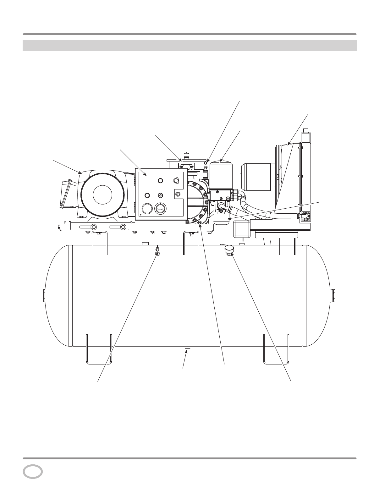
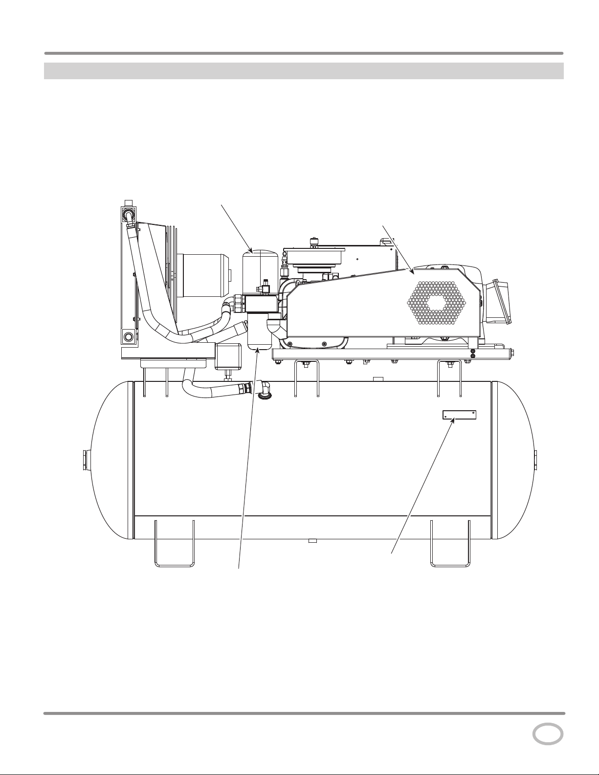
Getting To Know Your Compressor
Control Box
Motor
Air End Safety
Valve
Oil Cooler
Assembly
Air / Oil
Separator
Air End
Oil
Filter
Tank Safety Valve
Figure 1 - Components of the compressor
www.campbellhausfeld.com
4
Tank Drain
Oil
Drain
Tank Pressure
Gauge
Getting To Know Your Compressor
Air / Oil
Separator
Series CS Rotary Screw Compressors
Beltguard
Figure 2 - Components of the compressor
Oil Filter
ASME Label
www.campbellhausfeld.com
5
Operating Instructions
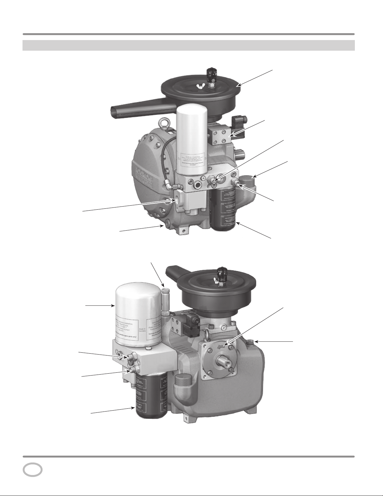
Getting To Know Your Compressor
Air Intake / Filter Assembly
Electric Control Unit
Oil Circulation
Connection / Outlet
Oil Fill Opening and Cap
Compressed
Air Outlet
Air / Oil Separating
Element
Oil Circulation
Connection / Outlet
Oil Circulation
Connection / Inlet
Oil Circulation
Connection / Inlet
Oil Drain Screw
Oil Filter
Safety Valve
Rotation Direction
Preset
Temperature Sensor
Connection
Oil Filter
Figure 3 - Components of the air end
www.campbellhausfeld.com
6
Series CS Rotary Screw Compressors
Unpacking
Do not lift or move unit without appropriately rated equipment. Be sure the unit is securely attached to lifting device used.
Do not lift unit by holding onto tubes or coolers. Do not use unit to lift other attached equipment.
After unpacking the unit, inspect carefully for any damage that may have occurred during transit. Check for loose, missing or
damaged parts. Check to be sure all supplied accessories are enclosed with the unit. In case of questions, damaged or missing parts,
please call 1-855-504-5678 for customer assistance.
Do not operate unit if damaged during shipping, handling or use. Damage may result in bursting and cause injury
or property damage.
Installation
Disconnect, tag and lock out power
source then release all pressure from the
system before attempting to install, service, relocate or perform
any maintenance.
Do not lift or move unit without appropriately
attached to lifting device used. Do not lift unit by holding onto tubes or
coolers. Do not use unit to lift other attached equipment.
Never use the wood shipping skids for mounting
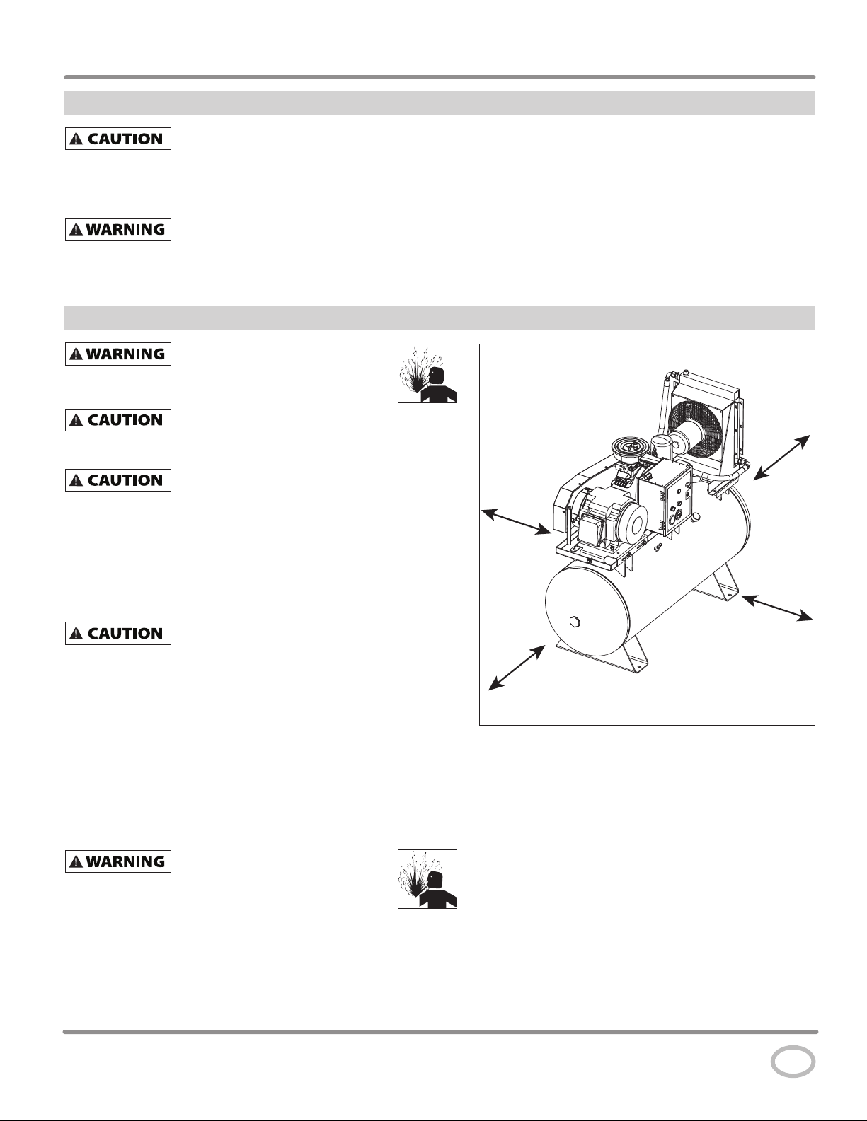
PICKING THE LOCATION
Install and operate unit at least 36 inches from any obstructions in a
clean, ventilated area. The surrounding air temperature should not
exceed 100° F or fall below 40° F. This will ensure an unobstructed
flow of air to cool compressor and allow adequate space for
maintenance.
Do not locate the compressor air inlet near
source of contamination.
NOTE: If compressor operates in a hot, moist environment, supply
compressor pump with clean, dry outside air. Supply air should be
piped in from external sources.
TANK MOUNTING
The tank should be bolted into a flat, even, concrete floor or on a
separate concrete foundation.
If using isolator pads, do not draw bolts tight. Allow the pads
to absorb vibrations. When isolators are used, a flexible hose or
coupling should be installed between the tank and service piping.
Failure to properly install the tank can
possible bursting.
rated equipment. Be sure the unit is securely
the compressor.
steam, paint spray, sandblast areas or any other
lead to cracks at the welded joints and
36 inches
36 inches
36 inches
36 inches
Figure 4 - Location
www.campbellhausfeld.com
7
Operating Instructions
Installation (Continued)
PIPING
Never use plastic (PVC) pipe for compressed air.
Serious injury or death could result.
Any tube, pipe or hose connected to the unit must be able to
withstand the temperature generated and retain the pressure. All
pressurized components of the air system must have a pressure
rating of 200 psi or higher. Incorrect selection and installation
of any tube, pipe or hose could result in bursting and injury.
Connect piping system to tank using the same size fitting as the
discharge port.
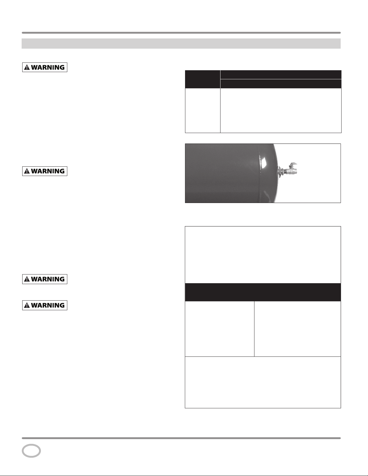
INSTALLING A SHUT-OFF VALVE
A shut-off valve should be installed on the discharge port of the
tank to control the air flow out of the tank. The valve should be
located between the tank and the piping system.
Never install a shut-off valve between the
compressor pump and the tank. Personal injury
and/or equipment damage may occur. Never use reducers in discharge
piping.
When creating a permanently installed system to distribute
compressed air, find the total length of the system and select
pipe size from the chart. Bury underground lines below the
frost line and avoid pockets where condensation can gather and
freeze.
Apply air pressure to the piping installation and make sure
all joints are free from leaks BEFORE underground lines are
covered. Before putting the compressor into service, find and
repair all leaks in the piping, fittings and connections.
WIRING (see page 9 for wiring diagrams)
All wiring and electrical connections must be
performed by a qualifi ed electrician familiar
with induction motor controls. Installations must be in accordance
with local and national codes.
Overheating, short circuiting and fi re damage
will result from inadequate wiring.
Wiring must be installed in accordance with National Electrical
Code and local codes and standards that have been set up
covering electrical apparatus and wiring. These should be
consulted and local ordinances observed. Be certain that
adequate wire sizes are used, and that:
1. Service is of adequate ampere rating.
2. The supply line has the same electrical characteristics
(voltage, cycles and phase) as the motor. Refer to motor
name plate for electrical ratings and specifications.
3. The line wire is the proper size and that no other equipment
is operated from the same line. The chart gives minimum
recommended wire sizes for compressor installations.
MINIMUM PIPE SIZE FOR COMPRESSED AIR LINE
Length Of Piping System
CFM
25 feet 50 feet 100 feet 250 feet
10 1/2 inch 1/2 inch 3/4 inch 3/4 inch
20 3/4 inch 3/4 inch 3/4 inch 1 inch
40 3/4 inch 1 inch 1 inch 1 inch
60 3/4 inch 1 inch 1 inch 1 inch
100 1 inch 1 inch 1 inch 1-1/4 inch
Figure 5 - Shut-off Valve
MINIMUM WIRE SIZE
(USE A MINIMUM OF 75°C COPPER WIRE)
Make sure voltage is correct with the motor wiring.
NOTE: If using 208 volts single phase, make sure the motor
name plate states it is rated for 208 volts single phase. 230 volt
single phase motors do not work on 208 volts unless they have
the 208 volt rating.
Three Phase
HP 208/230V 460/575V
5 12 AWG 14 AWG
7.5 10 AWG 12 AWG
10 8 AWG 12 AWG
15 6 AWG 10 AWG
20 3 AWG 8 AWG
25 3 AWG 8 AWG
Recommended wire sizes may be larger than the minimum set up by
local ordinances. If so, the larger size wire should be used to prevent
excessive line voltage drop. The additional wire cost is very small
compared with the cost of repairing or replacing a motor electrically
“starved” by the use of supply wires which are too small.
www.campbellhausfeld.com
8
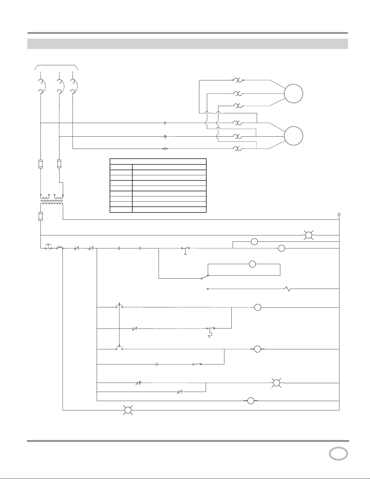
Wiring Diagram
TO SUPPLY
L1
L2 L3
Series CS Rotary Screw Compressors
OL
OL
OL
T4
T5
T6
M1
FAN
MOTOR
ESTOP
OFF
M
L1
M
L2
M
L3
OL
OL
OL
T1
T2
M2
T3
COMP
MOTOR
LEGEND
CT CONTROL TRANSFORMER
COL COIL OVERLOAD
FOL FAN OVERLOAD
HATR HIGH AIR TEMPERATURE RELAY
HPR HIGH PRESSURE RELAY
TR TIMER RELAY
TPS SWITCH, TANK PRESSURE
CT
ON
COL
FOL
M CONTACTOR-MAIN
HPS SWITCH, HIGH PRESSURE
HATR 1
HPR 1
POWER ON
HOUR
TR
TPs
5
METER
TR
M
7
INLET
VALVE
w
RESET
G
HATR 2
9
HATR 3
HATR
13
14
HATS
24
5
HPR 2
HPR 3
HPS
26
HPR
R
TR
www.campbellhausfeld.com
9
Operating Instructions
Installation (Continued)
GROUNDING
Improperly grounded electrical
components are shock hazards.
Make sure all the components are properly grounded to
prevent death or serious injury.
This product must be grounded. Grounding reduces
the risk of electrical shock by providing an escape wire for the
electric current if short circuit occurs. This product must be
installed and operated with a cable that has a grounding wire.
BREAKERS AND FUSES
The entire electrical system should be checked by a certified
electrician. Time delay breakers and fuses are required for this
compressor. A tripped breaker or blown fuses may indicate a
direct short to ground, high current draw, improper wiring,
incorrect fuse or breaker size and/or type. This needs to be
evaluated by a certified electrician.
MOTOR HOOKUP AND STARTER INSTALLATION
Branch circuit protection must be provided as specified in
the United States National Electrical Code, Chapter 2, “Wiring
Design and Protection.” Article 210, using the applicable article
“For Motors and Motor Controllers,” (Article 430,
Table 430-1 52).
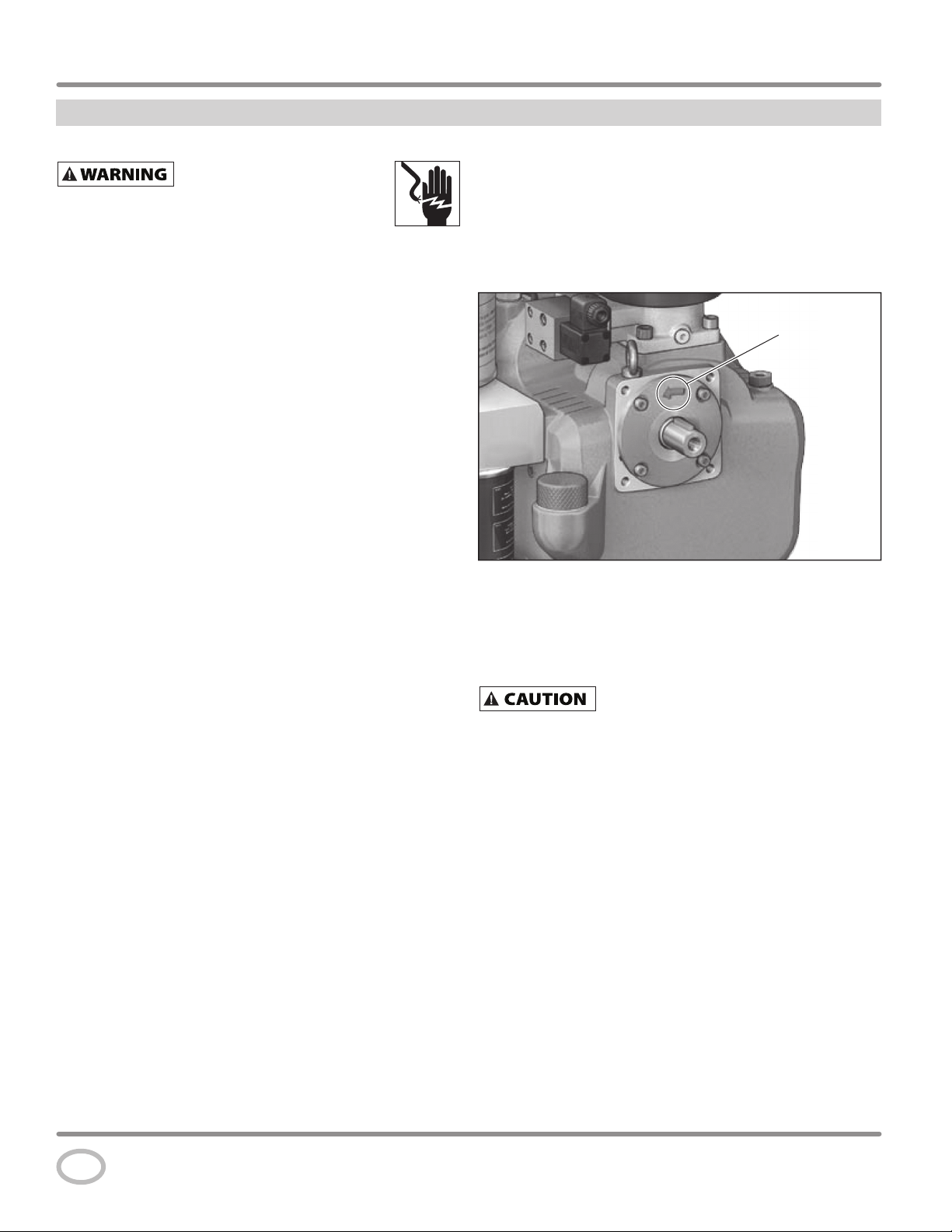
DIRECTION OF ROTATION
NOTE: Improper rotation will result in failure or compressor.
The direction of rotation must be counterclockwise (as shown
by the arrow on the air end in Figure 6) while facing the flywheel
side of the pump.
The direction of rotation of 3 phase motors can be reversed by
interchanging any two motor-line leads.
Rotation
Figure 6 - Direction of rotation
CHECKING ROTATION DIRECTION
ROTATION DIRECTION: rotating to the left (counterclockwise)
looking at the shaft.
The rotation direction of the screw compressor
system must be checked during initial start-up
and each time changes are made to the electrical supply line of the
electric motor drive. For this purpose, switch on the drive motor briefl y
and then switch off again immediately. ROTATION FOR MORE THAN
2 SECONDS IN THE WRONG ROTATION DIRECTION WILL DESTROY
THE SCREW COMPRESSOR. If necessary, reverse the connections of the
connecting cable.
www.campbellhausfeld.com
10
Installation (Continued)
LUBRICATION
THIS UNIT CONTAINS OIL. Before operating
compressor, check oil level (see Figure 7).
Using any other type of oil may shorten pump
life and result in damage.
Recommended Oil
Single viscosity ISO100 rotary screw compressor oil (Part
number GS903800AV - 1 Gallon Container). Available from
Campbell Hausfeld, please call 1-855-504-5678 for customer
assistance.
Oil Capacity
2.1 gallons
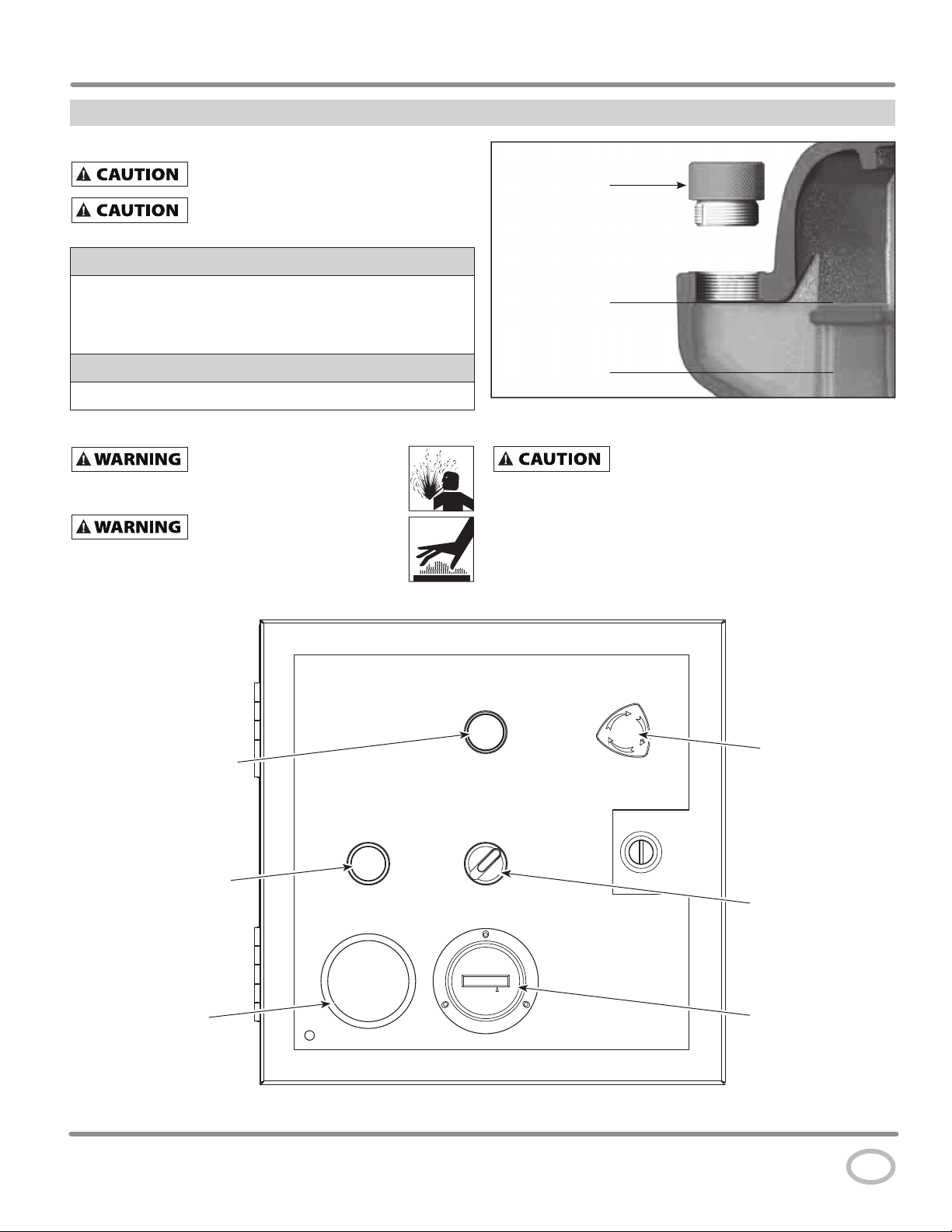
OIL LEVEL
Disconnect, tag and lock out
power source then release all
pressure from the system before attempting to install,
service, relocate or perform any maintenance.
RISK OF BURNS! The unit parts, oil,
and screw plug can be hotter than
175° F (80° C)! Wear personal safety equipment!
Series CS Rotary Screw Compressors
Oil Plug
Maximum
(cold oil level)
Minimum
(cold oil level)
Figure 7 - Oil Level
With hot oil, the oil level can be approximately
3/4 inch higher than with cold oil shortly after
discharging.
An important factor for the operating safety of the compressor
system is the oil level in the oil reservoir. The oil level check must
be performed before initial operation of the compressor and
then repeated every 100 operating hours.
Power Indicator
(WHITE)
High Temperature /
High Pressure
Indicator Light
and Reset (RED)
Temperature
Gauge
Figure 8 - Control Panel
E-Stop
ON / OFF Switch
[Lighted when in
ON position (GREEN)]
Hour Meter
www.campbellhausfeld.com
11
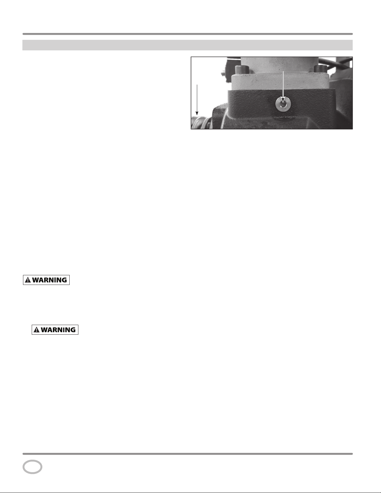
Operating InstructionsOperating Instructions
Prime Port
Pulley
Installation (Continued)
OIL LEVEL CHECK (See Figure 7)
• Check oil level by removing oil plug.
• With hot oil, the level will be higher than with cold oil.
As a result, oil may escape when the oil plug is opened at the
maximum oil level. If this does happen, close the oil plug
immediately and carefully clean up the oil that has escaped.
NOTE: The oil plug is provided with a safety hole on the side
from which oil or air escapes if there is any residual pressure
in the air end. Wait for one minute after the unit is at standstill
before opening the oil plug.
1. Switch off the system, prevent it from being switched back
on without authorization.
2. Wait for one minute at standstill.
3. Unscrew the oil plug on the filler neck by hand with the air
end depressurized.
4. Check the oil level.
5. If necessary, top off oil of the same oil type and the same
brand up to the maximum level (see Figure 7 and Lubrication
section).
NOTE: The oil filler neck is positioned so that it is not possible to
overfill the system. Excess oil runs out of the filler neck.
6. Screw on the oil plug firmly by hand.
7. Switch on the system.
8. Wipe off and clean up any spilled oil.
START-UP INFORMATION
READ AND UNDERSTAND ALL STEPS BELOW
BEFORE TURNING ON POWER .
1. Check oil level (See Figure 7).
2. If it has been longer than 12 weeks since the compressor has
been operated the air end must be primed with 8 ounces of
oil.
units must be checked for leaks and proper function. Loose
connections must be refastened and damaged lines must be
replaced.
Screw compressor systems that are switched off, shut down,
or stored for longer than 12 weeks cannot be placed into
operation again until after the following steps have been
carried out:
a. Manually rotate the compact module screw compressor
in the rotation direction several times.
b. With the compressor system stopped, add approximately
8 ounces of oil (same oil type as in the air end) into the
rotor chamber (see Figure 9).
c. Once again, manually rotate the compressor module
compressor stage in the rotation direction several times.
Before resuming operation, the
electrical equipment and all safety-relevant
Prime Port
Pulley
Figure 9 - Air End Priming Location
d. Check the oil level in the air end and top off if necessary
(see Maintenance section).
e. Monitor operation of the compressor system for at least
15 minutes, but at least until the steadystate temperature
is reached (continuous operating temperature).
3. Direction of rotation must be checked. Operation of the
air end for more than 2 seconds in the wrong direction will
destroy the screw compressor.
4. Check direction of rotation by quickly bumping the power to
ON and having someone else watch the motor pulley to see
which way it turns. Belt guard should remain installed. Also
check the direction of rotation of the oil cooler fan. The fan
must suck air in from the wire guard side and push air out
through the radiator when turning the correct direction. This
can be checked by holding a small strip of paper in front of
the radiator. With the correct direction of rotation the paper
will blow out away from the radiator.
5. Reset E-Stop switch if needed (see Figure 8).
6. Turn on the incoming power at the disconnect switch/circuit
breaker. The White incoming power indicator lamp will
illuminate. The motor will not turn on with this step.
7. Turn the on/off switch to the On position. The green lamp
will illuminate indication the compressor is ready to run.
The RED High temperature/High Pressure Failure Lamp will
illuminate. The motor will not turn on with this step.
8. Keep your hand on the on/off switch ready to turn off
immediately after start up to check the rotation direction.
Also check the direction of the cooler fan.
9. The motor can now be started by pressing the High temp/
high pressure reset. The red lamp is also a momentary
contact switch. The motor will start with this step.
10. Immediately turn off the on/off switch. The motor will stop
with this step.
11. If the direction of rotation is incorrect, disconnect, lock out
and tag out all incoming power. Change the position of two
of the incoming power lines and repeat steps 5-10.
12. When the direction of rotation has been confirmed the
compressor is ready to run for an initial start up operation
check.
www.campbellhausfeld.com
12
 Loading...