

Page 1

UT30 WEATHER STATION
INSTALLATION MANUAL
REVISED: 4/98
COPYRIGHT (c) 1993-1998 CAMPBELL SCIENTIFIC, INC.
Page 2

WARRANTY AND ASSISTANCE
The
is warranted by CAMPBELL SCIENTIFIC, INC. to be free from defects in materials and
UT30
workmanship under normal use and service for twelve (12) months from date of shipment unless specified
otherwise. Batteries have no warranty. CAMPBELL SCIENTIFIC, INC.'s obligation under this warranty is
limited to repairing or replacing (at CAMPBELL SCIENTIFIC, INC.'s option) defective products. The
customer shall assume all costs of removing, reinstalling, and shipping defective products to CAMPBELL
SCIENTIFIC, INC. CAMPBELL SCIENTIFIC, INC. will return such products by surface carrier prepaid.
This warranty shall not apply to any CAMPBELL SCIENTIFIC, INC. products which have been subjected
to modification, misuse, neglect, accidents of nature, or shipping damage. This warranty is in lieu of all
other warranties, expressed or implied, including warranties of merchantability or fitness for a particular
purpose. CAMPBELL SCIENTIFIC, INC. is not liable for special, indirect, incidental, or consequential
damages.
Products may not be returned without prior authorization. To obtain a Returned Materials Authorization
(RMA), contact CAMPBELL SCIENTIFIC, INC., phone (435) 753-2342. After an applications engineer
determines the nature of the problem, an RMA number will be issued. Please write this number clearly on
the outside of the shipping container. CAMPBELL SCIENTIFIC's shipping address is:
CAMPBELL SCIENTIFIC, INC.
RMA#_____
815 West 1800 North
Logan, Utah 84321-1784
CAMPBELL SCIENTIFIC, INC. does not accept collect calls.
Non-warranty products returned for repair should be accompanied by a purchase order to cover the repair.
815 W. 1800 N.
Logan, UT 84321-1784
USA
Phone (435) 753-2342
FAX (435) 750-9540
www.campbellsci.com
Campbell Scientific Canada Corp.
11564 -149th Street
Edmonton, Alberta T5M 1W7
CANADA
Phone (403) 454-2505
FAX (403) 454-2655
Campbell Scientific Ltd.
Campbell Park
80 Hathern Road
Shepshed, Leics. LE12 9RP
ENGLAND
Phone (44)-50960-1141
FAX (44)-50960-1091
Page 3

TABLE OF CONTENTS
PAGE
1. PREPARATION AND SITING
1.1 Installation Tasks....................................................................................................................1-1
1.2 Tools Required.......................................................................................................................1-1
1.3 Siting and Exposure ...............................................................................................................1-3
1.4 Determining True North for Wind Vane Orientation...............................................................1-5
.............................................................................................1-1
2. TOWER/TRIPOD INSTALLATION
2.1 Tower/Tripod Installation
2.2 Sensor Mounting Brackets
3. INSTRUMENTATION INSTALLATION
3.1 Enclosure, Datalogger, and Power Supply
3.2 Sensor Connection
3.3 Communication and Data Storage Peripherals
3.4 Sealing and Desiccating the Enclosure
4. SENSOR INSTALLATION
4.1 034A Met One Windset........................................................................................................ .. 4-1
4.2 014A Met One Wind Speed Sensor.......................................................................................4-1
4.3 024A Met One Wind Direction Sensor ................................................................................... 4-2
4.4 05103 and 05305 RM Young Wind Monitors .........................................................................4-2
4.5 03001 RM Young Wind Sentry Wind Set...............................................................................4-3
4.6 03101 RM Young Wind Sentry Anemometer.........................................................................4-3
4.7 LI200S Li-Cor Silicon Pyranometer/LI190SB Quantum Sensor.............................................4-4
4.8 107/108 Temperature Probe..................................................................................................4-4
4.9 107B Soil Temperature Probe................................................................................................4-5
4.10 CS500 Vaisala Temperature and RH Probe..........................................................................4-5
4.11 HMP35C Vaisala Temperature and RH Probe....................................................................... 4-6
4.12 CS105 Vaisala Barometric Pressure Sensor .........................................................................4-6
4.13 TE525 Texas Electronics Tipping Bucket Rain Gage ............................................................ 4-7
4.14 CS700-L Rain Gage...............................................................................................................4-7
4.15 SR50 Sonic Ranging Sensor..................................................................................................4-8
4.16 CS615-L Water Content Reflectometer .................................................................................4-8
4.17 237 Leaf Wetness Sensor......................................................................................................4-9
4.18 257 Soil Moisture Sensor .......................................................................................................4-9
4.19 Wind Direction Sensor Orientation....................................................................................... 4-10
...................................................................................................4-1
...................................................................................2-1
...........................................................................3-1
5. SOFTWARE INSTALLATION
6. MAINTENANCE AND TROUBLESHOOTING
6.1 Maintenance........................................................................................................................... 6-1
6.2 Troubleshooting......................................................................................................................6-2
.............................................................................................5-1
..............................................................6-1
I
Page 4

TABLE OF CONTENTS
LIST OF TABLES
3.3-1 Station ID Numbers and Corresponding Switch Settings**..................................................3-12
3.3-2 Station ID Numbers and Corresponding Switch Settings.....................................................3-14
LIST OF FIGURES
2.1-1 UT30 Tower-Based Weather Station ..................................................................................... 2-1
2.1-2 Top View of Base and Guy Anchor Layout.............................................................................2-1
2.1-3 Foundation for B18 Base........................................................................................................2-2
2.1-4 B18 Concrete Mounting Base................................................................................................. 2-3
2.1-5 RFM18 Flat Roof Mounting Base...........................................................................................2-3
2.1-6 UTEYE Eyebolt Guy Anchor...................................................................................................2-3
2.1-7 UTDUK Duckbill Guy Anchor.................................................................................................. 2-4
2.1-8 Guy Wire Attached to Tower ..................................................................................................2-4
2.1-9 Guy Wire/Turnbuckle Attached to UTEYE Anchor.................................................................2-5
2.1-10 Ground Rod and Clamp..........................................................................................................2-5
2.1-11 Tower Grounding Clamp ........................................................................................................2-5
2.2-1 Top View of Tower.................................................................................................................. 2-6
2.2-2 019ALU Crossarm and Lightning Rod.................................................................................... 2-6
2.2-3 UT12VA Gill Radiation Shield and UT018 Crossarm............................................................. 2-7
2.2-4 UTLI Leveling Fixture/Crossarm Mount and UT018...............................................................2-7
2.2-5 025 Pyranometer Crossarm Stand.........................................................................................2-7
3.1-1 ENC 12/14 Enclosure on CM6/CM10.....................................................................................3-1
3.1-2 ENC 12/14 Enclosure on UT10..............................................................................................3-1
3.1-3 ENC 16/18 Enclosure on UT30..............................................................................................3-1
3.1-4 21X Mounted Inside of the ENC 12/14 Enclosure..................................................................3-2
3.1-5 21X Alkaline Batteries ............................................................................................................3-2
3.1-6 21XL Rechargeable Batteries................................................................................................. 3-3
3.1-7 BPALK 12 Volt Power Supply.................................................................................................3-3
3.1-8 PS12LA 12 Volt Power Supply ............................................................................................... 3-4
3.1-9 MSX10 Solar Panel ................................................................................................................3-4
3.2-1 Routing and Wiring Sensor Leads to the Datalogger............................................................. 3-5
3.3-1 SM192/SM716 Storage Module..............................................................................................3-6
3.3-2 DC112 Modem with 6362 Surge Protector.............................................................................3-7
3.3-3 COM100 Cellular Transceiver................................................................................................3-7
3.3-4 SRM-5A and SC932 at Datalogger ........................................................................................3-9
3.3-5 SRM-5A Wiring.....................................................................................................................3-10
3.3-6 RF95 RF Modem and RF100/RF200 Transceiver ............................................................... 3-11
3.3-7 RF232 Base Station Installation ...........................................................................................3-13
3.3-8 MD9 Multidrop Interface.......................................................................................................3-13
3.3-9 MD9 Multidrop Interface at the Computer ............................................................................3-15
3.4-1 Enclosure Supply Kit.............................................................................................................3-16
4.1-1 Met One 034A Wind Speed and Direction Sensor................................................................. 4-1
4.2-1 Met One 014A Wind Speed Sensor.......................................................................................4-1
4.3-1 Met One 024A Wind Direction Sensor ...................................................................................4-2
4.4-1 05103 RM Young Wind Monitor ............................................................................................. 4-2
4.5-1 03001 Mounted to the Mast....................................................................................................4-3
4.5-2 03001 Mounted to 019ALU Crossarm....................................................................................4-3
4.6-1 03101 RM Young Wind Sentry Anemometer.........................................................................4-3
4.7-1 LI200S/LI190SB and LI2003S Leveling Fixture...................................................................... 4-4
4.8-1 107 Temperature Probe .........................................................................................................4-4
4.10-1 CS500 Temperature and RH Probe....................................................................................... 4-5
4.11-1 HMP35C Vaisala Temperature and RH Probe.......................................................................4-6
4.12-1 CS105 Vaisala Barometric Pressure Sensor in a Custom Weather Station Enclosure......... 4-6
4.12-2 CS105MD Vaisala Barometric Pressure Sensor in a MetData1 Enclosure ........................... 4-6
4.13-1 TE525 Texas Electronics Rain Gage.....................................................................................4-7
4.14-1 CS700-L Rain Gage and CM100 Mounting Bracket...............................................................4-7
II
Page 5

TABLE OF CONTENTS
4.15-1 SR50 Sonic Ranging Sensor..................................................................................................4-8
4.16-1 CS615 Water Content Reflectometer with CS615G Probe Insertion Guide .......................... 4-8
4.17-1 237 Leaf Wetness Sensor......................................................................................................4-9
4.18-1 257 Soil Moisture Sensor ....................................................................................................... 4-9
4.19-1 Magnetic Declination for the Contiguous United States.......................................................4-10
4.19-2 Declination Angles East of True North Are Subtracted From 0 to Get True North...............4-11
4.19-3 Declination Angles West of True North Are Added to 0 to Get True North..........................4-11
III
Page 6

SECTION 1. PREPARATION AND SITING
These guidelines apply to several different Campbell Scientific weather stations.
1.1 INSTALLATION TASKS
1.1.1 INDOORS
• Immediately upon receipt of your
shipment…
⇒ Open shipping cartons.
⇒ Check contents against invoice.
Contact CSI immediately about any
shortages.
• Several days prior to the planned
installation date…
⇒ Collect tools and site information
(Section 1)
⇒ Assemble datalogger, communications
device, and power supply in enclosure
(Section 3)
⇒ Install datalogger support software on
PC (Section 5)
⇒ Install instrumentation enclosure
(Section 3)
⇒ Install sensors (Section 4)
• UT30 (10 meter tower) tower stations:
⇒ Install 3 to 10 meter level sensors
(Section 4)
⇒ Raise tower (Section 2)
⇒ Install instrumentation enclosure
(Section 3)
⇒ Install 0 to 3 meter level sensors
(Section 4)
• ET101 / ET106 ET Stations:
⇒ Place instrumentation enclosure low on
the ET Tower (Section 3)
⇒ Install sensor option (Section 4)
⇒ Establish communications between the
datalogger and the PC (Section 5)
⇒ Program datalogger, test sensors, and
retrieve data (Section 5)
⇒ Trial run the tower / tripod installation,
assembling as much as possible
(Section 2)
⇒ Repackage equipment for transport to
the field site
1.1.2 OUTDOORS
• Locate suitable site (Section 1)
• Prepare tower or tripod base (Section 2)
• Tripod and UT10 (3 meter tower) tower
stations:
⇒ Raise tripod or tower (Section 2)
⇒ Slide enclosure to top of tower and
secure with correct orientation (Section 3)
1.2 TOOLS REQUIRED
Tools required to install and maintain a weather
station are listed below.
1.2.1 TOOLS FOR TOWER INSTALLATION All Towers
Shovel
Rake
Open end wrenches: 3/8", 7/16", ½",
(2) 9/16"
Magnetic compass
6' Step ladder
CM6/CM10
Tape measure (12')
Level (12" to 24")
Small sledge hammer
Teflon tape or pipe dope
Allen hex wrench (5/64)
1-1
Page 7

SECTION 1. PREPARATION AND SITING
UT10
Tape measure (12' to 20')
Level (24" to 36")
Pick or digging bar
Claw Hammer
Materials for concrete form:
Hand saw
(4) 12" wood stakes
(1) 2"x 4"x 8' piece of lumber
(8) 8p double-head nails
(8) 16p double-head nails
Concrete trowels
(2) 1 to 1.5" thick x 24" boards
to support base above
forms (optional)
Concrete (0.4 cubic yards)
ET Tower
Tape measure (12’ to 20’)
Claw hammer
Level (24” to 36”)
Hand saw
Materials for concrete form:
(4) 1" x 2" x 12" stakes
(2) 2" x 4" x 96" lumber
(12) 8p double-head nails
(8) 16p double-head nails
20 ft form wire
½ Yard concrete
Concrete trowel, edger
Electrical Fish tape or 20 feet of
small diameter rope
Wheelbarrow
UT30
Tape measure (12' and 20')
Nut driver (3/8")
Level (36" to 48")
Small sledge hammer
Pliers
Tie wire
Climbing harness
Hard hat
Haul rope (50')
Non-stretch line (20')
Wire rope cutters
Materials for B18 Base and UTEYE Anchors:
(4) Wood stakes 12"
Pick or digging bar
Concrete form materials (2"x 4"
lumber, stakes, saw,
hammer, nails, etc.)
Concrete trowel and edger
Materials for UTDUK Duckbill Anchors
Sledgehammer
Highlift jack
Chain (to attach jack to anchor
loops)
Materials for RFM18 Base:
(3) anchors appropriate for
mounting surface
(3) bolts and washers to secure
base to anchors
1.2.2 TOOLS FOR INSTRUMENTATION AND MAINTENANCE
All Towers
Lock and key for enclosure
Magnetic declination angle (Section 4)
Magnetic compass
Straight bit screwdrivers (small,
medium, large)
Phillips-head screwdrivers (small,
medium)
Small diagonal side-cuts
Needle-nose pliers
Wire strippers
Pocket knife
Calculator
Volt / Ohm Meter
Electrical Tape
Step ladder (6')
Datalogger prompt sheet (Section 6)
Station manuals
Station log and pen
Open end wrenches: 3/8", 7/16", ½", (2)
9/16"
Socket wrench and 7/16" deep well
socket
Adjustable wrench
Pliers
Conduit and associated tools (as
required)
Felt-tipped marking pen
Claw hammer
Pipe wrench (12")
CM6/CM10
Tape measure (12')
Level (12" to 24")
Teflon tape or pipe dope
UT10
Tape measure (12' to 20')
3/8" nut driver
Level (24" to 36")
Teflon tape or pipe dope
(12) ¼" washers (for the 015 Crossarm
stand only)
Allen wrench set
1-2
Page 8

SECTION 1. PREPARATION AND SITING
UT30
Tape measure (12' to 20')
3/8" nut driver
Level (36" to 48")
Pliers
Climbing harness
Hard hats
50' haul rope
Crescent wrench
Channel-lock pliers
¼" washers (spacers for U-bolts)
5/64" Allen hex wrench
1.2.3 SUPPLIES FOR POWER AND COMMUNICATIONS OPTIONS
AC Power
Wire, conduit, and junction boxes as
needed
Phone Modem
Hayes compatible calling modem for PC
Phone line to weather station or
junction box
Short-Haul Modem
4 Conductor communications cable
from PC to weather station or
junction box
6' copper ground rod and clamp for PC
surge protection (optional)
1.3 SITING AND EXPOSURE
CAUTION: If any part of the weather
station comes in contact with power lines,
you could be killed. Contact local utilities
for the location of buried utility lines before
digging or driving ground rods.
Selecting an appropriate site for the weather
station is critical in order to obtain accurate
meteorological data. In general, the site should
be representative of the general area of interest,
and away from the influence of obstructions
such as buildings and trees.
The weather station should not be located
where sprinkler irrigation water will strike
sensors or instrument enclosure.
1.3.1 WIND SPEED AND DIRECTION
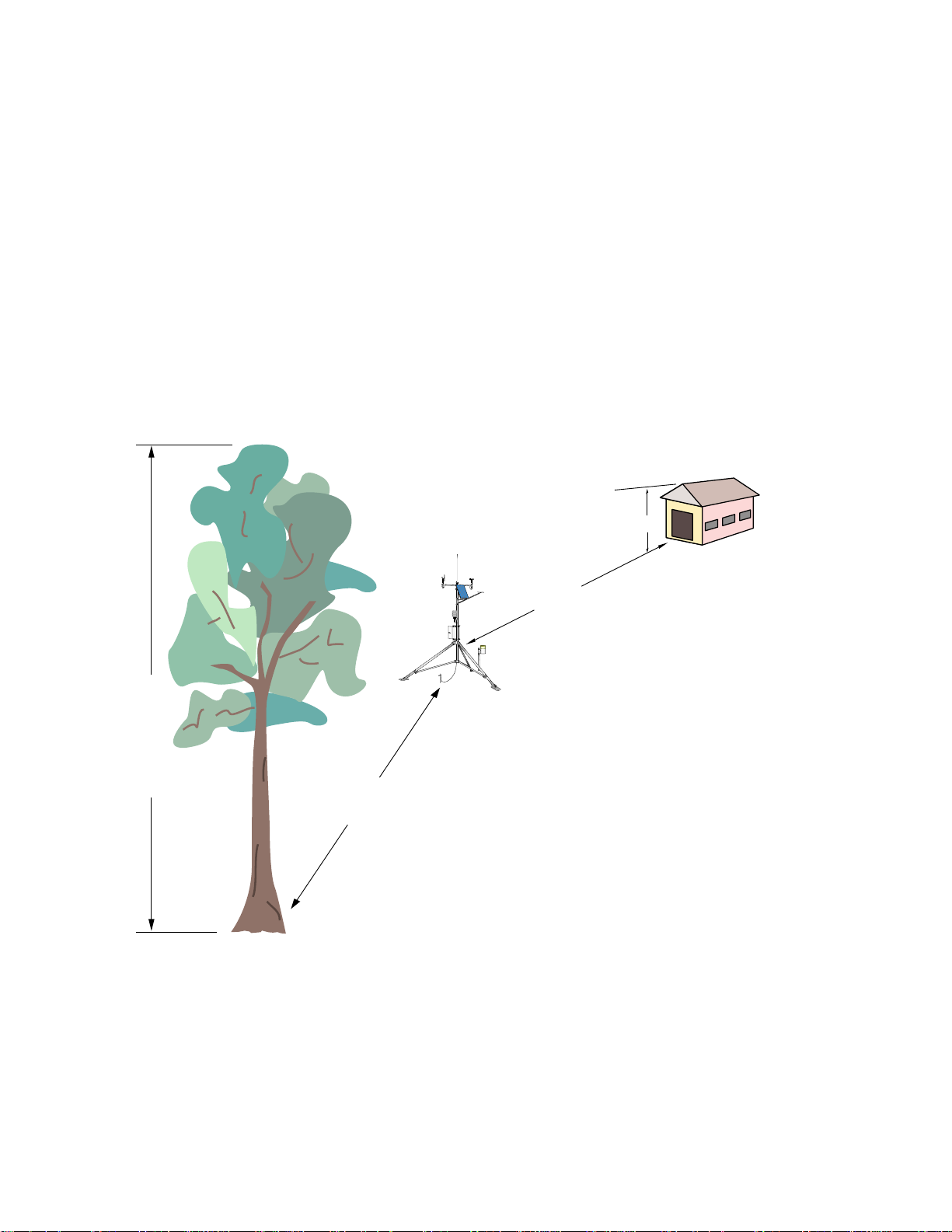
Wind sensors should be located over open level
terrain, and at a distance of at least ten times
(EPA) the height of any nearby building, tree or
other obstruction, as illustrated in Figure 1.3-1.
Standard measurement heights:
3.0 m ± 0.1 m recommended (AASC)
2.0 m ± 0.1 m, 10.0 m ± 0.5 m optional (AASC)
10.0 m (WMO and EPA)
1.3.2 TEMPERATURE AND RELATIVE HUMIDITY
Sensors should be located over an open level
area at least 9 m (EPA) in diameter. The
surface should be covered by short grass, or
where grass does not grow, the natural earth
surface. Sensors should be located at a
distance of at least four times the height of any
nearby obstruction and at least 30 m (EPA)
from large paved areas. Sensors should be
protected from thermal radiation, and
adequately ventilated.
Situations to avoid include:
• large industrial heat sources
• rooftops
• steep slopes
• sheltered hollows
• high vegetation
• shaded areas
• swamps
• areas where snow drifts occur
• low places holding standing water after
rains
Standard measurement heights:
1.5 m ± 1.0 m (AASC)
1.25 - 2.0 m (WMO)
2.0 m temperature (EPA)
2.0 m and 10.0 m for temperature difference
(EPA)
1.3.3 PRECIPITATION
A rain gage should be sited on level ground that
is covered with short grass or gravel. In open
areas, the distance to obstructions should be
two to four times (EPA, AASC) the height of the
obstruction.
Some general guidelines for site selection are
listed below, which were condensed from EPA
(1988)
1
, WMO (1983)2, and AASC (1985)
3
publications.
The height of the opening should be as low as
possible, but should be high enough to avoid
splashing from the ground. Wind shields, such
as those used by the National Weather Service,
are recommended for open areas.
1-3
Page 9
SECTION 1. PREPARATION AND SITING
Collectors should be heated, if necessary, to
properly measure frozen precipitation. The
gage must be mounted above the average level
of snow accumulation in areas that experience
significant snowfall.
Standard measurement heights:
1.0 m ± 1.0 cm (AASC)
30.0 cm minimum (WMO, EPA)
1.3.4 SOLAR RADIATION
Pyranometers should be located to avoid
shadows on the sensor at any time. Mounting it
on the southern most (northern hemisphere)
portion of the weather station will minimize the
chance of shading from other weather station
structures. Reflective surfaces and sources of
artificial radiation should be avoided. The height
at which the sensor is mounted is not critical.
1.3.5 SOIL TEMPERATURE
The measurement site for soil temperature should
2
be at least 1 m
and typical of the surface of
interest. The ground surface should be level with
respect to the immediate area (10 m radius).
Standard measurement depths:
10.0 cm ± 1.0 cm (AASC)
5.0 cm, 10.0 cm, 50.0 cm, 100.0 cm (WMO)
H
Height of tree (T)
REGCOMENDED
FeedSENSORS
27115
Serial
PortlandOr USA
REGCOMENDED
FeedSENSORS
Serial2711527115
PortlandOr USA
REGCOMENDED
FeedSENSORS
Serial
27115
PortlandOr USA
10H
10T
FIGURE 1.3-1. Effect of Structure on Wind Flow
1-4
Page 10
SECTION 1. PREPARATION AND SITING
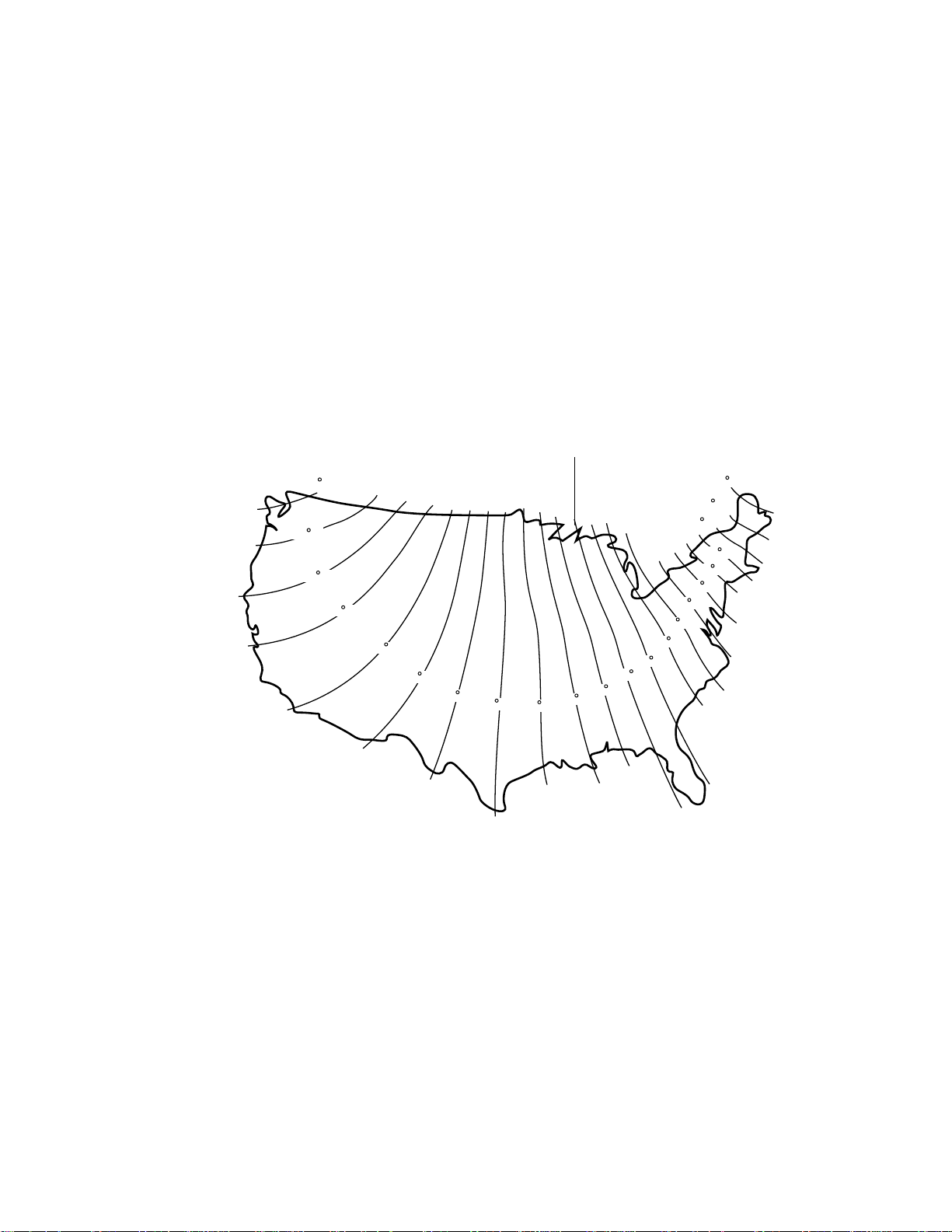
1.4 DETERMINING TRUE NORTH FOR WIND VANE ORIENTATION
Magnetic declination, or other methods to find True
North, should be determined prior to installing the
weather station. True North is usually found by
reading a magnetic compass and applying the
correction for magnetic declination*; where
magnetic declination is the number of degrees
between True North and Magnetic North. Magnetic
declination for a specific site can be obtained from a
USFA map, local airport, or through an internet
service called NSSDC CGM (Section 1.4.1). A
general map showing magnetic declination for the
contiguous United States is shown in Figure 1.4-1.
Subtract declination from 360° Add declination to 0°
22 E
20 E
18 E
16 E
14 E
12 E
10 E
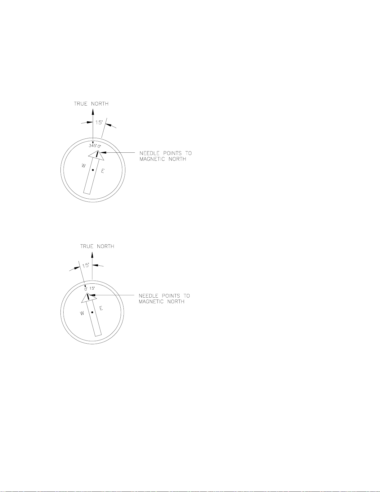
Declination angles east of True North are
considered negative, and are subtracted from 0
degrees to get True North as shown Figure 1.4-2.
Declination angles west of True North are considered positive, and are added to 0 degrees to get
True North as shown in Figure 1.4-3. For
example, the declination for Logan, Utah is 14.5°
East. True North is 360° - 14.5°, or 345.5° as read
on a compass.
* Other methods employ observations using
the North Star or the sun, and are
discussed in the Quality Assurance
Handbook for Air Pollution Measurement
Systems, Volume IV - Meteorological
4
.
20 W
18 W
16 W
14 W
12 W
10 W
8 W
6 W
4 W
2 W
0
8 E
Measurements
4 E
6 E
2 E
FIGURE 1.4-1. Magnetic Declination for the Contiguous United States
1-5
Page 11

SECTION 1. PREPARATION AND SITING
1.4.1 NSSDC CGM SERVICE
The NSSDC CGM (Corrected Geomagnetic)
Service provides an easy way of determining
magnetic declination of a specific site. Since
magnetic declination fluctuates with time, it
should be determined each time the wind vane
orientation is adjusted. It can be accessed on
the world wide web at
http://nssdc.gsfc.nasa.gov/space/cgm/cgm.html
If you know the latitude and longitude of your
site, fill out Form 1as shown below for an
accurate magnetic declination. If you do not
know the latitude and longitude of your site, fill
out Form 2 for estimate of magnetic declination.
Note that longitude is expressed in 0 to 360
degrees east of the Greenwich prime meridian,
and that north latitudes are positive.
Geographic Alt. CGM IGRF Magnetic Field Dipole
Lat. Long. (km) Lat. Long. H(nT) D(deg) Z(nt) Lat. Long.
Query Form 1: Latitude/Longitude
Latitude/Longitude below specified in:
Geographic
Year (from 1945 to 2000): 1998
Altitude above Earth's surface (km) [from 0.
to 40000.]: 0
Latitude (degrees) [from -90.00 to 90.00]:
42.03
Longitude (degrees) [from 0.00 to 360.00]:
248.15
Query Form 2: Image Map
Year (from 1945 to 2000): 1998
Altitude above Earth's surface (km)
[0. - 40000.]: 0
Click on map to specify location and submit:
(select area on map provided)
A table containing similar information to the
following will be returned after submitting Forms
1 or 2.
42.03 248.15 0. 49.80 311.06 20608. 14.417 50505. 49.68 312.14
1-6
Page 12
SECTION 1. PREPARATION AND SITING
Magnetic declination is bold in this example to
show its location in the table. A positive
declination is east, while a negative declination
is west. The declination in this example is
14.417 degrees. As shown in Figure 1.4-1, the
declination for Logan, UT is east, so True North
for this site is 360 - 14.417, or 345.5 degrees.
FIGURE 1.4-2. Declination Angles East of
True North Are Subtracted From 0 to Get
True North
References
1
EPA, (1987). On-Site Meteorological Program
Guidance for Regulatory Modeling Applications,
EPA-450/4-87-013. Office of Air Quality
Planning and Standards, Research Triangle
Park, North Carolina 27711.
2
WMO, (1983). Guide to Meteorological
Instruments and Methods of Observation.
World Meteorological Organization No. 8, 5th
edition, Geneva, Switzerland.
3
The State Climatologist, (1985) Publication of
the American Association of State
Climatologists: Height and Exposure Standards
for Sensors on Automated Weather Stations,
v. 9, No. 4 October, 1985.
4
EPA, (1989). Quality Assurance Handbook for
Air Pollution Measurement Systems, EPA Office
of Research and Development, Research
Triangle Park, North Carolina 27711.
FIGURE 1.4-3. Declination Angles West of True
North Are Added to 0 to Get
True North
1-7
Page 13
SECTION 2. UT30 TOWER INSTALLATION
REGCOMENDED
FeedSENSORS
PortlandOr USA
Serial
27115
REGCOMENDED
FeedSENSORS
PortlandOr USA
Serial
27115
REGCOMENDED
FeedSENSORS
PortlandOr USA
Serial2711527115
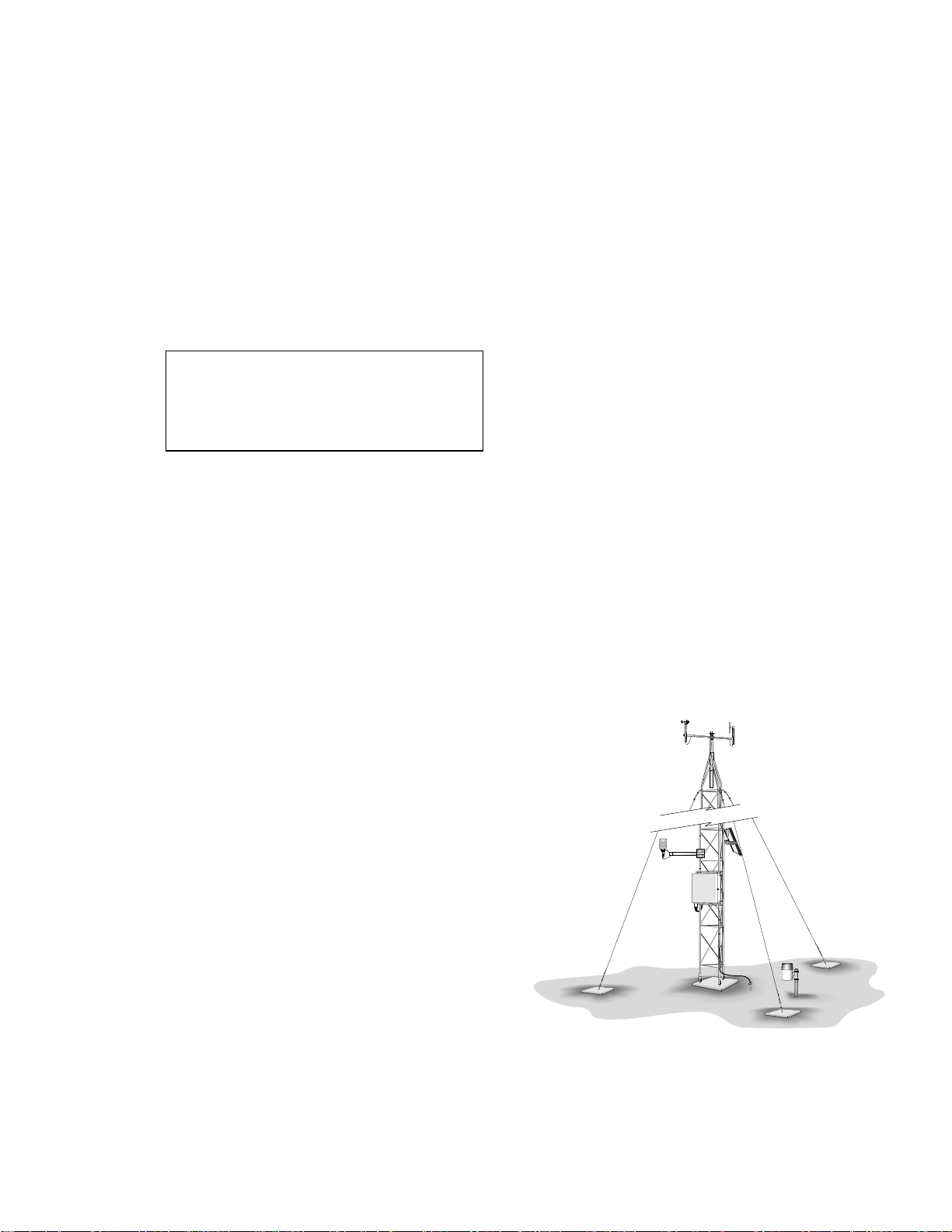
2.1 UT30 TOWER INSTALLATION
The UT30 10 meter tower provides a support
structure for mounting the weather station
components. Figure 2.1-1 shows a typical
UT30 equipped with instrumentation enclosure,
meteorological sensors, and solar panel.
2.1.1 TOWER INSTALLATION SAFETY CONCERNS
WARNING: Tower installation near power
lines is dangerous. The minimum safe
recommended distance from overhead
power lines is 2 times the height of the
tower and mast combined.
When installing the tower, remember:
• DO NOT use a metal ladder
• DO NOT work on a wet or windy day
• DO dress properly−shoes with rubber soles
and heels, rubber gloves, and long sleeves.
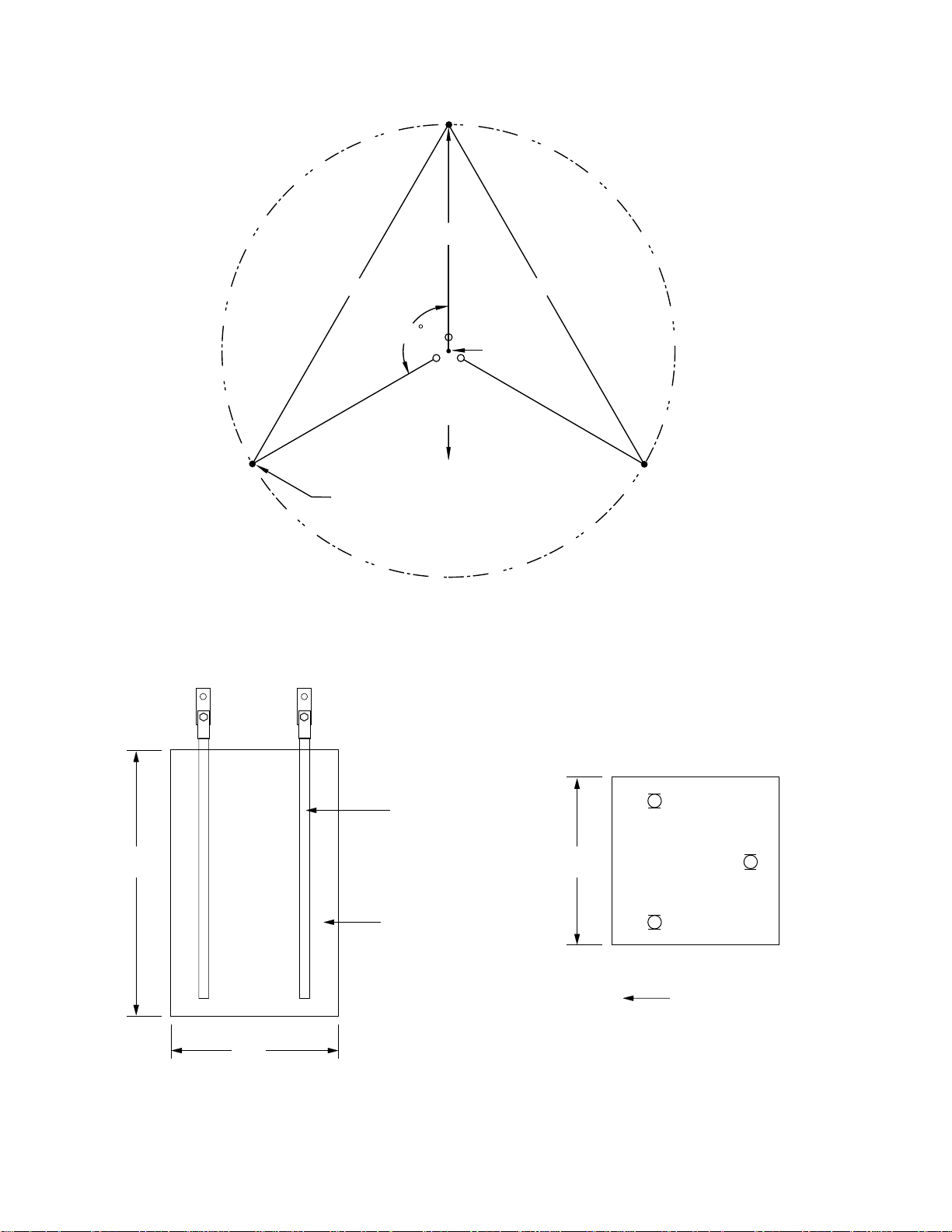
2.1.2 BASE AND GUY ANCHOR LAYOUT
1. A guyed UT30 tower requires an area
approximately 17 feet in diameter. Brush and
tall weeds should be removed, otherwise the
natural vegetation and ground surface should
be disturbed as little as possible.
2. Drive a stake where the base of the tower
will be located. Attach a line to the stake
and scribe a circle with a 17 foot radius.
Drive a stake on the scribed line opposite
the direction the tower will hinge for the first
guy anchor location (Figure 2.1-2).
2.1.3.1 B18 Base installation
1. Dig a hole 36" square and 48" deep where
the tower base will be located (Figure 2.1-3).
2. Optionalconstruct a concrete form out of
2" x 4" lumber 36" square (inside
dimensions). Center the form over the hole
and drive two stakes along the outside edge
of each side. Level the form by driving nails
through the stakes and into the form while
holding the form level.
3. Attach the bottom section of the tower to
the B18 base using one bolt per leg, making
sure that the hinge direction is common for
all legs.
4. Center the bottom tower section with the
base attached in the hole. Orient the
tower/base for the proper hinge direction.
Make sure that the top of the legs will be at
least 1/2" above the finished height of the
concrete (Figure 2.1-4).
5. Fill the hole with concrete. Getting the
bottom tower section plumb is very
important. As concrete is poured into the
hole, periodically check the tower for plumb
using a carpenter's level and make
adjustments as necessary. Allow three to
four days for the concrete to cure.
On level ground, lay out the remaining two
anchor locations by measuring 29.5 feet
from the first anchor to the scribed line on
either side of the base stake (Figure 2.1-2).
On unlevel ground, use a compass at the
base stake to lay out the remaining two
anchor locations 120 degrees from the first.
Vary the distance between the tower and
each anchor so that the angle between the
tower and the guy wire will be approximately
30 degrees.
2.1.3 TOWER BASE INSTALLATION
FIGURE 2.1-1. UT30 Tower-Based
Weather Station
There are two base options: the B18 base is
poured in concrete; the RFM18 roof mount base
is anchored to a flat surface.
2-1
Page 14
SECTION 2. TOWER INSTALLATION
17 '
RADIUS
29.5 '
120
TILT DIRECTION
(NORTH)
ANCHOR LOCATIONS
(3) PLCS
29.5 '
CENTER POINT
FIGURE 2.1-2. Top View of Base and Guy Anchor Layout
SIDE VIEW
TOP VIEW
2-2
48"
36"
B18 Base
ANCHOR BOLT
(3) places
36"
Cement
CEMENT
Foundation
FOUNDATION
FIGURE 2.1-3. Foundation for B18 Base
North
Page 15
2.1.3.2 RFM18 Base Installation
UT3B#B
(tripods)
RFM18
(tripods)
60
Eyebolt
Cement foundation
24 "
24 "
SIDE VIEW
1. Position the RFM18 on the surface where it will
be installed. Make sure the hinge direction is
correct and mark the locations of the three
mounting holes. Install an appropriate anchor
(user-supplied) for each hole.
Attach the bottom section of the tower to
the RFM18 base using one bolt per leg
(Figure 2.1-5). Position the base over the
anchor holes. Secure the base to the
anchors with appropriate hardware (usersupplied). Check the tower for plumb and
shim the RFM18 if necessary before fully
tightening the bolts.
SECTION 2. TOWER INSTALLATION
B18
(3) places
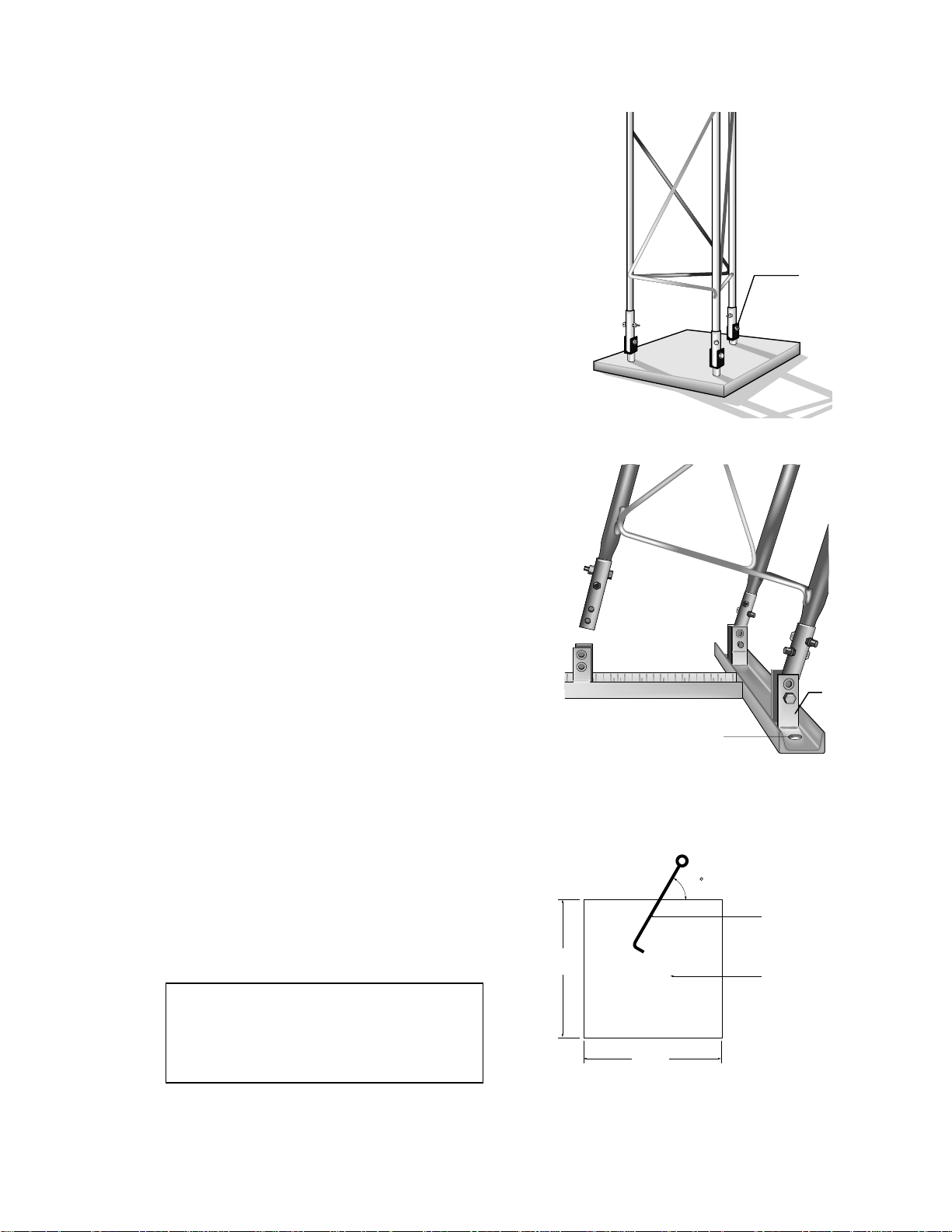
2.1.4 GUY ANCHOR INSTALLATION
There are two types of anchors for the tower
guy wires: the UTEYE eye bolts are poured in
concrete; the UTDUK duckbill anchors are
driven into the soil.
2.1.4.1 UTEYE Eyebolt Guy Anchor
1. Dig a hole 24" square by 24" deep at each
anchor location (Section 2.1.2).
2. Optionalconstruct a concrete form out of
2" x 4" lumber 24" square (inside
dimensions) for each hole. Center the
forms over the holes and level them using a
carpenter's level and stakes.
3. Fill the holes with concrete and install the
eyebolts as shown in Figure 2.1-6.
2.1.4.2 UTDUK Duckbill Guy Anchor
1. Locate the three anchor locations (Section
2.1.2). It is important that the anchors be
driven at the same angle as the guy wires
(Figure 2.1-7). Insert the steel drive bar into
the anchor body and drive the anchor into
the ground using a fence post driver or
sledgehammer until only the top half of the
loop remains above the ground.
2. Attach a high-lift jack to the loop and jack
the anchor up about 6 inches to rotate the
anchor into the load-lock position.
WARNING: Failure to install and lock the
anchor at the correct angle will result in the
anchor cable cutting through the soil until
the angles equalize, causing slack in the
guy wires.
FIGURE 2.1-4. B18 Concrete Mounting Base
RFM18
Mounting Hole
(3) places
FIGURE 2.1-5. RFM18 Flat Roof
Mounting Base
Tower →
Eyebolt
Cement
Foundation
FIGURE 2.1-6. UTEYE Eyebolt Guy Anchor
2-3
Page 16

SECTION 2. TOWER INSTALLATION
2.1.5 UT30 10 M TOWER ASSEMBLY
1. Having previously installed the base and
bottom tower section (Section 2.1.4), remove
the bolt from the rear tower leg, and loosen
the bolt in the side legs so the bottom tower
section is free to hinge. Tilt the tower section
to the ground and assemble the remaining
sections and mast using the hardware
provided with the tower.
2. Install the guy wires to the top of the tower
(Figure 2.1-8). Cut the 120' piece of guy wire
into three pieces; lengths will vary with slope.
Attach the guy wires to the tower using two Ubolts for each guy wire.
3. Mounting brackets and sensors that attach to
upper tower sections are most easily attached
while the tower is lying on the ground.
4. "Walk" the tower to its upright position and
install the remaining bolts in the tower base.
5. Attach the guy wires to the anchors (Figure
2.1-9). Unscrew the jaw and eye bolts until 1
inch of thread extends through the turnbuckle
body. Attach the jaw end of the turnbuckles to
the anchors. While holding the tower plumb,
attach the guy wires to the eye end of the
turnbuckles using a thimble and two U-bolts
for each guy wire. Tighten the turnbuckles
until the guy wires are snug and the tower is
plumb. Do not overtighten the turnbuckles.
2.1.6 UTGND TOWER GROUNDING KIT
Drive Bar
Duckbill Anchor
FIGURE 2.1-7. UTDUK Duckbill Guy Anchor
U-bolts
(2) places
Tower →
o
60
1. Drive the ground rod close to the tower
(Figure 2.2-1) using a fence post driver or
sledgehammer. Drive the rod at an angle if
an impenetrable hardpan layer exists. In hard
clay soils, a gallon milk jug of water can be
used to "prime" the soil and hole to make
driving the rod easier.
2. Loosen the bolt that attaches the clamp to
the ground rod. Insert one end of the 4
AWG wire between the rod and the clamp
and tighten the bolt (Figure 2.1-10).
3. Attach the tower grounding clamp to a
tower leg (Figure 2.1-11). Route the 4
AWG wire attached to the ground rod up
the tower leg to the grounding clamp.
Loosen the set screw and insert the 4 AWG
wire and the 24 AWG enclosure ground
wire into the hole behind the set screw and
tighten the set screw. Route the green wire
to where the enclosure will be installed.
2-4
FIGURE 2.1-8. Guy Wire Attached to Tower
Page 17

Turnbuckle
SECTION 2. TOWER INSTALLATION
U-bolt
(2) places
Wire to
Enclosure
Clamp
Thimble
Wire to
Ground Rod
FIGURE 2.1-9. Guy Wire/Turnbuckle
Attached to UTEYE Anchor
Clamp
Ground Rod
FIGURE 2.1-11. Tower Grounding Clamp
FIGURE 2.1-10. Ground Rod and Clamp
2-5
Page 18

SECTION 2. TOWER INSTALLATION
2.2 SENSOR MOUNTING BRACKETS
Sensor mounting brackets provide a means of
mounting the sensors to the tower. General
orientation of the mounting brackets is shown in
Figure 2.2-1.
2.2.1 019ALU CROSSARM SENSOR MOUNT
1. Loosen the two bolts that secure the mast
to the top tower section. Extend the mast
16" (swaged end up) above the top of the
tower and tighten the bolts.
2. Attach the 019ALU crossarm to the mast as
shown in Figure 2.2-2. Position the middle
NU-RAIL at the base of the swaged mast
section. Orient the 019ALU in a north/south
direction, with the 3/4" NU-RAIL facing
south (northern hemisphere) and tighten the
set screws.
3. Install the lightning rod to the mast as
shown in Figure 2.2-2. Loosen the two
screws on the lightning rod mounting
bracket. Position the mounting bracket 2"
down from the top of the mast and tighten
both screws evenly. Make sure the
lightning rod set screw is tight.
1" NU-RAIL
Enclosure
UT018 Crossarm
Lightning Rod
Ground Rod
UT30
RFM18
019ALU Crossarm
3/4" NU-RAIL
FIGURE 2.2-1. Top View of Tower
NORTH
2.2.2 GILL RADIATION SHIELDS
1. Attach the Gill Radiation Shield (UT12VA,
UT12P, or UT6P) to the UT018 crossarm
with the bolt and nut provided (Figure 2.2-3).
2. Attach the UT018 to the tower leg facing the
prevailing wind direction (Figure 2.2-3). The
top of the crossarm mounting bracket should
be 74" from the bottom of the tower. Tighten
the four nuts on the compression bracket to
secure the crossarm.
2.2.3 UTLI LEVELING FIXTURE AND CROSSARM MOUNT
1. Attach the UTLI leveling fixture to the UT018
crossarm with the nut and bolt provided
(Figure 2.2-4).
2. Attach the UT018 to a tower leg so that the
crossarm faces south (northern hemisphere).
The top of the crossarm mounting bracket
should be 98 inches from the bottom of the
tower. Tighten the four nuts on the
compression bracket to secure the crossarm.
Lightning Rod
019ALU
FIGURE 2.2-2. 019ALU Crossarm and
Lightning Rod
2-6
Page 19

2.2.4 025 PYRANOMETER CROSSARM STAND
1. Attach the LI2003S Leveling Fixture to the
025 Pyranometer Crossarm Stand using the
three screws provided (see Figure 2.2-5).
2. Position the 025 mounting plate 5" above
the 3/4" x 3/4" NU-RAIL and tighten the set
screws.
NOTE: The 025 mounts to the 3/4" x 3/4"
NU-RAIL (PN 1017) on the 019ALU
Crossarm, which may not be available
depending on the wind sensor
configuration.
SECTION 2. TOWER INSTALLATION
UT018
UTLI
UT018
UT018
UT12VA
FIGURE 2.2-3. UT12VA Gill Radiation Shield
and UT018 Crossarm
FIGURE 2.2-4. UTLI Leveling
Fixture/Crossarm Mount and UT018
025
019ALU
FIGURE 2.2-5. 025 Pyranometer
Crossarm Stand
2-7
Page 20

SECTION 3. INSTRUMENTATION INSTALLATION
3.1 ENCLOSURE, DATALOGGER, POWER SUPPLY
3.1.1 ENCLOSURE
All instrumentation (datalogger, power supply,
and communication peripherals) are mounted in
the enclosure. A PVC bulkhead port is installed
in the enclosure for routing the sensor and
communication cables to the instrumentation.
Mount the enclosure to the mast as shown in
Figure 3.1-1.
1. Position the enclosure on the north side of the
mast or tower (northern hemisphere) as shown
in Figure 3.1-1, 3.1-2, or 3.1-3. Attach the
enclosure with the U-bolts provided.
2. Route the 14 AWG wire from the brass
tripod grounding clamp (Section 2) to the
enclosure grounding lug. Strip one inch of
insulation from each end of the wire and
insert the end of the wire into the grounding
lugs and tighten the set screws.
13” (CM6), 47.5” (CM10)
To Top Of Bell Reducer
59”
To Base
Mounting
Bracket
ENC 12/14
FIGURE 3.1-2. ENC 12/14 Enclosure on
UT10
Upper
Mounting
Bracket
and U-Bolt
FIGURE 3.1-1. ENC 12/14 Enclosure on
CM6/CM10
59”
To Base
FIGURE 3.1-3. ENC 16/18 Enclosure on
UT30
3-1
Page 21

SECTION 3. INSTRUMENTATION INSTALLATION
BPALKEXP
(power supply)
Alkaline
Pannasonic
D
Alkaline
Pannasonic
D
Alkaline
Pannasonic
D
Alkaline
D
Pannasonic
SERIAL I/O
CR10X
MEASUREMENT AND CONTROL MODULE
firmware 1983, 1986, 1995
S/N: X 1012
C
CR10X WIRING PANEL
MADE IN USA
WIRING
PANEL NO.
G 12V
POWER
IN
EARTH
CROUND
SE
DEF
G
G
H
L
AG
H
L
AG
E3
AG
G
G
L
AG
H
4
7
8
5
9
10
6
11
12
AG
G
G
G
SW 12V CTRL
SW 12V
G
SE
DEF
G
G
H
L
AG
H
L
AG
E3
AG
L
AG
H
1
1
2
2
3
4
3
5
6
G
G
H
L
AG
H
L
AG
E3
12V
12V
L
AG
H
SDM
LOGAN, UTAH
INTERNAL BATTERY
MADE IN USA
12V ALKALINE BATTERY PACK
BPALK
Logan, Utah
TEMPORARY BATTERY
3.1.2 CR10X DATALOGGER
The CR10X Datalogger and PS12 12 V Power
Supply mount to the enclosure backplate as
shown in Figure 3.1-7. Two screws (PN 447)
attach the CR10X, four screws (PN 505) attach
the PS12.
3.1.3 BPALK ALKALINE POWER SUPPLY
Cover
The BPALK battery pack houses eight alkaline "D"
cell batteries. To install the batteries, loosen the
thumb screw and remove the cover (Figure 3.1-7).
1. Make sure the red and black wires attached
to the left end of the BPALK are connected
to the “12 V” and “G” terminals on the
CR10X.
2. Disconnect the battery pack from the
external connector on the left end of the
BPALK. Remove the battery pack and
insert eight alkaline “D” cell batteries.
Replace the battery pack.
3. Connect the battery pack to the external
connector labeled “INTERNAL BATTERY” and
replace the cover.
3.1.4 PS12LA RECHARGEABLE POWER SUPPLY
The PS12LA houses a sealed monoblock
rechargeable battery. To install the battery,
loosen the two thumb screws and remove the
cover (Figure 3.1-8).
1. With the PS12 power switch "OFF", insert
the battery and plug the battery lead into the
connector labeled "INT".
Alkaline
Batteries
"12 V" and
"G" Wires
FIGURE 3.1-7. BPALK 12 Volt Power Supply
3.1.5 MSX10 SOLAR PANEL
Solar panels purchased from CSI are shipped
with a charge plug taped to the back of the
panel. The charge plug is not used with the
PS12LA. Refer to the solar panel manual for
installation instructions.
2. Make sure the red and black wires attached
to the "+12 V" and "
" terminals on the
PS12 are connected to the "12 V" and "G"
terminals on the CR10X Wiring Panel.
3. An AC transformer or unregulated solar panel
(Section 3.1-5) should be connected to the
PS12LA at all times. Connect the lead wires
from the transformer or solar panel without
regard to polarity to the two terminals labeled
"CHG" (Figure 3.1-8); the red LED should light
when voltage is present.
NOTE: The wall transformer converts 120
VAC input to 18 VAC output. Maximum
charging current is 1.1 A.
WARNING: Maximum input voltage into the
"CHG" terminals is 26 VAC or 26 VDC. Do not
connect 110 VAC directly to "CHG" terminals.
4. Turn power switch to "ON", and replace cover.
3-2
1. Mount the MSX10 solar panel to the mast,
facing south (northern hemisphere) as
shown in Figure 3.1-9. Position the MSX10
at the top of the 1 1/4 inch diameter section
of the mast. Install the U-bolt, muffler
clamp, and nuts as shown in Figure 3.1-9.
2. The solar panel should be oriented to
receive maximum insolation over the
course of the year. Suggested tilt angles
(referenced to the horizontal plane) are
listed below.
Site Latitude Tilt Angle
0 - 10 degrees 10 degrees
11 - 20 Latitude + 5 degrees
21 - 45 Latitude + 10 degrees
46 - 65 Latitude + 15 degrees
> 65 80 degrees
Page 22

3. After determining the tilt angle, loosen the
1012
INT
EXT
BATT
CHG
OFF
ON
CHG
CHG
CHG
Y
UASA
BATTERY
Y U A S A
NP7 - 12 12
*
CHARGING INSTRUCTION (AT 2000 )
SERIAL I/O
CR10X
MEASUREMENT AND CONTROL MODULE
firmware 1983, 1986, 1995
S/N: X 1012
C
CR10X WIRING PANEL
MADE IN USA
WIRING
PANEL NO.
G 12V
POWER
IN
EARTH
CROUND
SE
DEF
G
G
H
L
AG
H
L
AG
E3
AG
G
G
L
AG
H
4
7
8
5
9
10
6
11
12
AG
G
G
G
SW
12V CTRL
SW
12V
G
SE
DEF
G
G
H
L
AG
H
L
AG
E3
AG
L
AG
H
1
1
2
2
3
4
3
5
6
G
G
H
L
AG
H
L
AG
E3
12V
12V
L
AG
H
SDM
LOGAN, UTAH
two bolts that attach the mounting bracket
to the panel. Adjust the angle, then tighten
the bolts. Secure the lead wire to the mast
using wire ties.
SECTION 3. INSTRUMENTATION INSTALLATION
PS12 POWER SUPPLY
WITH 12V CHARGING REGULATOR
Logan, Utah
MADE IN USA
WARNING:
PERMANENT DAMAGE TO RECHARGEABLE
CELLS MAY RESULT IF DISCARGED
BELOW 10.5 VOLTS
FUNCTION
INT
PS12 BATTERY
BAT
EXT
EXTERNAL BATTERY - DO NOT USE WITH
CHG
INTERNAL RECHARGEABLE BATTERY
POWER TO +12 TERMINALS
OFF
ON
CHG
INPUT FROM CHARGER OR SOLAR PANEL
CHG
16-26 VDC OR AC RMS: POSITIVE TO
+12
+12
EITHER TERMINAL, NEGATIVE TO OTHER
POWER TO DATALOGGER OR
12V PERIPHERALS
INT
BATT
EXT
CHG
ON
OFF
CHG
CHG
+12
+12
"12 V" and
"G" Wires
Mounting
Bracket
U-bolt
FIGURE 3.1-9. MSX10 Solar Panel
3.2 SENSOR CONNECTION
1. After the sensors have been mounted, route
the sensor leads through the entry hole in
the bottom of the enclosure and to the
datalogger. Secure the leads to the left
side of the enclosure using cable ties and
tabs (Figure 3.2-1). Any excess cable
should be neatly coiled and secured to the
tabs.
2. To connect a lead wire, loosen the
appropriate screw terminal and insert the
lead wire (wires should be stripped 5/16”),
and tighten the screw using the screwdriver
provided with the datalogger.
FIGURE 3.1-8. PS12LA 12 Volt
Power Supply
If a datalogger program has been
developed, the sensors will have to be
wired to the channels specified by the
measurement instructions.
If a program has not been developed, Short
Cut can be used to generate a program and
wiring diagram. Run Short Cut, and wire
the sensor leads as specified by the wiring
diagram in the .DEF file.
For more complex programming, or when
sensors are used which are not supported
by Short Cut, EDLOG (PC208 Software)
must be used. If desired, wire the sensors
and develop the program using EDLOG and
the measurement instructions as shown in
Section 5.
3-3
Page 23

SECTION 3. INSTRUMENTATION INSTALLATION
Strain Relief at
Datalogger
Strain Relief
Using Cable
Tabs and Ties
Sensor Leads
FIGURE 3.2-1. Routing and Wiring Sensor Leads to the Datalogger
3.3 COMMUNICATION AND DATA STORAGE PERIPHERALS
One or more peripherals (i.e., storage modules,
modems, etc.) can be mounted to the enclosure
backplate (ENC 12/14 or ENC 16/18
enclosures).
3.3.1 SM192/SM716 STORAGE MODULE
MADE IN USA
SW 12V CTRL
5V 5V G G
P1 G P2 G C8 C7 C6 C5 C4 C3 C2 C1 G 12V 12V
WARNING:
PERMANENT DAMAGE TO RECHARGEABLE
CELLS MAY RESULT IF DISCHARGED
BELOW 10.5 VOLTS
FUNCTION
INT
PS12 BATTERY
BAT
EXTERNAL BATTERY - DO NOT USE WITH
EXT
INTERNAL RECHARGEABLE BATTERY
CHG
CHARGE VOLTAGE PRESENT
ON
OFF
INPUT FROM CHARGER OR SOLAR PANEL
CHG
16-26 VDC OR AC RMS: POSITIVE TO
CHG
EITHER TERMINAL, NEGATIVE TO OTHER
+12
+12
POWER TO DATALOGGER OR
12V PERIPHERALS
G 12V
G 12V
CS I/O
POWER
SW 12V
IN
CR10X WIRING PANEL
MADE IN USA
SDM
MADE IN FILAND
YAISALA
PRESSURE TRANSMITER
TYPE
PTA
SERIAL No.
413075
OUTPUT
0 - 5 VDC
SUPPLY
11 - 30 VDC
RANGE
600 - 1060 hpa
WIRING
PANEL NO.
427 A
PS12 POWER SUPPLY
WITH 12V CHARGING REGULATOR
Logan, Utah
910511 12
78
SE
6
4
DIFF
GH L
AGH L AG H L AG E3 AGG G
G
SE
34256
12
DIFF
3
1
G
GH L
AGH L AG H L AG E1 AGE2 G
EARTH
GROUND
3.3.2 COMM200/COM300 PHONE MODEMS
A phone modem enables communication between
the datalogger and the computer (with a Hayes
compatible phone modem) over a dedicated
telephone line. The COM300 additionally supports
voice synthesis for voice calls.
Mount the modem to the enclosure backplate
as shown in Figure 3.3-2.
Storage modules extend the amount of memory
that is available for storing data, and also
provide on-site backup for data and programs.
Mount the SM192 to the enclosure backplate as
shown in Figure 3.3-1.
1. Attach the mounting bracket (PN 6234)
to the backplate using the four screws
and nylon grommets provided.
2. Connect the storage module to the
datalogger's I/O port with an SC12
cable. Place the storage module in the
bracket and fasten the Velcro straps.
3-4
1. Mount the modem to the backplate using
the four screws and nylon grommets
provided.
2. Connect the modem to the datalogger's
I/O port with the SC12 cable provided.
3. The telephone company generally provides
surge protection, and a patch cord that
plugs into the RJ11C jack. If surge
protection has not been provided, the Model
6362 Surge Protector Kit can be installed to
the enclosure backplate. Connect the two
terminals on the surge protector to the "tip"
and "ring" terminals on the modem as
shown in Figure 3.3-2.
4. Refer to COM300 manual for COM300
programming instructions.
Page 24

12V 12V
EITHER TERMINAL, NEGATIVE TO OTHER
DIFFSEAG H L AG H L AG H L AG GGE3 AG
4 5 6
78 9101112
CAMPBELL
SCIENTIFIC
INC.
SE
12 34 56
1 2 3
AG H L AG H L AG H L AG GGE1 E2
DIFF
GGGG
SWITCHED
12V
SWITCHED
CONTROL
EARTH
G 5V5VP1P2 C8C7C6C5C4C3C2C1
SERIAL I/O
G 12V
POWER
IN
CR10
MADE IN USA
WIRING PANEL NO.
12V
SM192
FIGURE 3.3-1. SM192/SM716 Storage
Module
SECTION 3. INSTRUMENTATION INSTALLATION
SC12
Cable
Mounting
Bracket
+12
+12
POWER TO DATALOGGER OR
SW 12V CTRL
SW 12V
12V PERIPHERALS
G 12V
G 12V
POWER
IN
CR10X WIRING PANEL
MADE IN USA
SDM
thia ia
thia ia
thia
thia
thia
thia
thia
thia
thia
thia
thia
thia
thia
thia
thia
CS I/O
WIRING
PANEL NO.
thia
thia
thia
thia
thia
tryu to read this whoever
thia
thia
thia
thia
thia
thia
thia
thia
thia
thia
thia
thia
thia
thia
EARTH
GROUND
Logan, Utah
SE
DIFF
G
SE
DIFF
G
78
910511 12
4
GH L
AGH L AG H L AG E3 AGG G
12
34256
1
GH L
AGH L AG H L AG E1 AGE2 G
MADE IN USA
6
3
5V 5V G G
P1 G P2 G C8 C7 C6 C5 C4 C3 C2 C1 G 12V 12V
CAMPBELL
COM200 MODEM
SCIENTIFIC
INC.
Complies with Part 68, FCC rules. FCC Registration No. B9QUSA-75378-MM-T
Ringer Equivalence 0.6B. Required Connector USOC RJ11C. Canadian Load No.5
This equipment complies with the requirements in Part 15 of FCC Rules for Class A
computing device. Operation of this equipment in a residential area may cause
unacceptable interference to radio and TV reception requiring the operator to take
Burial Phone
Cable
whatever steps are necessary to correct the interference.
S/N
0002
Ground
Wires
GND
MADE IN USA
COM200
RING
TIP
FIGURE 3.3-2. DC112 Modem with 6362 Surge Protector
SC12 Cable
3-5
Page 25

SECTION 3. INSTRUMENTATION INTALLATION
POWER TO DATALOGGER OR
3.3.3 COM100 CELLULAR TRANSCEIVER
A cellular transceiver enables communication
between the datalogger and a PC (with a Hayes
compatible phone modem) over cellular service.
The COM100 requires either the COM200 or
COM300 modem.
Mount the COM100 in the enclosure as shown
in Figure 3.3-3 with the following steps:
1. Mount the COM100 to the enclosure
backplate using the four screws and nylon
grommets provided.
2. Connect the modem to the datalogger’s I/O
port with an SC12 cable.
3. Mount the cellular Yagi antenna on a
grounded mast, positioning it to point
toward the nearest cellular tower, with the
radiating elements oriented vertically.
Route the coaxial cable into the enclosure
through the wiring port and connect it to the
cellular transceiver’s coaxial connector.
Provide strain relief for the cable on the left
side of the enclosure with a cable tie and
tab.
4. Connect 12V, ground, and control lines as
described in the COM100 manual. Connect
the modem and RJ-11C interface with the
RJ-11 patch cord.
MADE IN USA
Logan, Utah
SE
910511 12
78
DIFF
6
4
G
GHL
AGH L AGH L AGE3 AGG G
12
SE
34256
1
DIFF
3
GHL
AGH L AGH L AGE1 AGE2 G
G
EARTH
GROUND
12V PERIPHERALS
G 12V
G 12V
SW 12V CTRL
POWER
SW 12V
IN
5V 5VG G
CR10X WIRING PANEL
MADE IN USA
SDM
P1 G P2 G C8 C7 C6 C5C4 C3 C2 C1 G 12V12V
CS I/O
WIRING
PANEL NO.
3.3.4 SRM-5A RAD MODEM AND SC932C INTERFACE
Rad Modems enable communication between
the datalogger and computer over 4-wire
unconditioned telephone line, or cable with two
twisted pairs of wires.
The maximum distance between modems is
determined by baud rate and wire gauge. At 9600
baud the approximate range is 5.0 miles using 19
gauge wire, 4.0 miles using 26 gauge wire.
Installation requirements depend on the type of
cable that is used, and how it is installed (direct
burial, conduit, etc.). In general, follow state
and local electrical codes.
A recommended rodent-proof burial cable is PN
F-02P22BPN, available from ANIXTER. Call
ANIXTER at (708) 677-2600 for the name of a
local distributor.
SRM-5A at the Datalogger
1. Plug the SRM-5A into the SC932(C). Position
the notched tabs in the mounting bracket over
the two screws in the SRM-5A (refer to Figure
3.3-4). Thread the SRM-5A screws through
the bracket and into the SC932(C).
thia ia
thia ia
thia
thia
thia
thia
thia
thia
thia
thia
thia
thia
thia
thia
thia
thia
thia
thia
thia
thia
tryu to read this whoever
thia
thia
thia
thia
thia
thia
thia
thia
thia
thia
thia
thia
thia
thia
2. Attach the SRM-5A and SC932(C) mounting
bracket to the enclosure backplate using the
two screws and nylon inserts provided (Figure
3.3-4).
CAMPBELL
COM200 MODEM
SCIENTIFIC
INC.
Complies with Part 68, FCC rules. FCC Registration No. B9QUSA-75378-MM-T
Ringer Equivalence 0.6B. Required Connector USOC RJ11C. Canadian Load No.5
This equipment complies with the requirements in Part 15 of FCC Rules for Class A
computing device. Operation of this equipment in a residential area may cause
unacceptable interference to radio and TV reception requiring the operator to take
RJ-11
Patch
whatever steps are necessary to correct the interference.
S/N
0002
Coax
Cable
to
Antenna
GND
RING
TIP
MADE IN USA
COM100
Transceiver
RJ-11C
Interface
DO NOT EAT
UNITED DESICCANTS-GATES
101CHRISTINE, BELEN, NOW MEXICO 87002
UNITED DESICCANTS-GATES
DESI PAK
101CHRISTINE, BELEN, NEW MEXICO 87002
SPECIFICATION MIL-D-3464 TYPE I &II
REACTIVATION TIME IN-BAG 16 HOURS AT 250 F
DESICCANT
ACTIVATED
CONTENTS
DESI PAK
BAGGED FOR
SPECIFICATION MIL-D-3464 TYPE I &II
4
REACTIVATION TIME IN-BAG 16 HOURS AT 250 F
UNITS
DESICCANT
DO NOT EAT
UNITED DESICCANTS-GATES
ACTIVATED
CONTENTS
101CHRISTINE, BELEN, NOW MEXICO 87002
BAGGED FOR
UNITS
DO NOT EAT
UNITED DESICCANTS-GATES
DESI PAK
101CHRISTINE, BELEN, NEW MEXICO 87002
SPECIFICATION MIL-D-3464 TYPE I &II
REACTIVATION TIME IN-BAG 16 HOURS AT 250 F
DESICCANT
ACTIVATED
CONTENTS
DESI PAK
BAGGED FOR
SPECIFICATION MIL-D-3464 TYPE I &II
4
PACKAGE USE
REACTIVATION TIME IN-BAG 16 HOURS AT 250 F
UNITS
DESICCANT
AND STATIC
DEHUMIDIFICATION
ACTIVATED
CONTENTS
BAGGED FOR
4
UNITS
DEHUMIDIFICATION
DO NOT EAT
DEHUMIDIFICATION
4
PACKAGE USE
AND STATIC
PACKAGE USE
AND STATIC
DEHUMIDIFICATION
O
PACKAGE USE
AND STATIC
O
FIGURE 3.3-3. COM100 Cellular Transceiver
3-6
SC12
Cable
DC112 or
VS1
Modem
3. Connect the SC932(C) to the datalogger's
I/O port with an SC12 cable.
4. Mount the 6361 Surge Protector to the
enclosure backplate using the hardware
provided. Connect the ground wire to the
enclosure ground lug (Figure 3.3-5).
5. Cut a 12" long piece of two twisted pair
cable and connect it to the SRM-5A as
shown in Figure 3.3-5. Fasten the cable to
the strain relief tab with a cable tie.
6. Route the cable previously attached to the
SRM-5A, and the two twisted pair cable
(from the other SRM-5A) to the 6361.
Connect the cables as shown in Figure 3.3-
5. Strain relief the cables to the side of the
enclosure using cable ties and tabs.
Page 26

SECTION 3. INSTRUMENTATION INSTALLATION
3.3.4.2 SRM-5A at the Computer
1. Mount the 6361 (or 5563) Surge
Protector to a flat surface (close to the
computer) using two screws. Ground
the center terminal to an earth (or
building) ground using a 12 AWG or
larger diameter wire.
2. Cut a piece of two twisted pair cable
long enough to reach from the 6361 to
the computer. Connect the cable to the
SRM-5A as shown in Figure 3.3-5.
Fasten the cable to the strain relief tab
with a cable tie. Connect the SRM-5A
to the computer's serial port.
3. Route the cable from the remote SRM5A, and the cable from the SRM-5A
attached to the computer to the 6361.
SRM-5A
EARTH
GROUND
Logan, Utah
SE
DIFF
GH L
G
SE
DIFF
G
GH L
910511 12
78
4
AG H L AG H L AG E3 AG G G
34256
12
1
AG H L AG H L AG E1 AG E2 G
Connect the cables as shown in Figure
3.3-5. Strain relief the cables using
cable ties and tabs.
3.3.5 RF95 RF MODEM AND RF100/RF200 TRANSCEIVER
Radiotelemetry (RF) enables communications
between one or more dataloggers and the
computer over an FCC-assigned radio
frequency in the VHF or UHF band. The
maximum distance between any two
communicating stations is approximately 20
miles and must be line-of-sight. Longer
distances and rough terrain may require
intermediate repeater station(s). Refer to the
Radiotelemetry Network Applications manual for
RF repeater stations and RF Networks
accessed remotely by phone.
SW 12V CTRL
SW 12V
12V PERIPHERALS
G 12V
G 12V
POWER
IN
CR10X WIRING PANEL
MADE IN USA
SDM
CS I/O
WIRING
PANEL NO.
MADE IN USA
6
3
5V 5V G G
P1 G P2 G C8 C7 C6 C5 C4 C3 C2 C1 G 12V 12V
SC12
--
RCV
+G +
XMT
Ground Lug
QC
CAMPBELL
SCIENTIFIC LTD
SC932 - S/N E1055
SC932C
6361
3-7
Page 27

SECTION 3. INSTRUMENTATION INTALLATION
Datalogger
Computer
3-8
FIGURE 3.3-5. SRM-5A Wiring
Page 28

SECTION 3. INSTRUMENTATION INSTALLATION
3.3.5.1 RF95 Modem and RF100/RF200 Transceiver at the Datalogger
Mount the RF95 RF Modem and the radio
transceiver to the enclosure backplate as
shown in Figure 3.3-6.
1. Remove the four screws that attach the
lid to the RF95 modem. Remove the
lid, then remove the single screw that
secures the circuit board to the base.
Remove the circuit board, and mount
the base to the enclosure backplate
using the two screws and plastic
grommets provided.
2. Set the dip switches on the circuit board
to the appropriate Station ID (Table
3.
3-1). Each RF95 must have a unique
station ID; address 1 is usually used for
the base station, address 2 for first
remote station, address 3 for the next
remote station, etc. Switch 9 should be
in the "OPEN" position. Reassemble
the circuit board and lid. Do not tighten
the four lid screws at this time.
Logan, Utah
SE
78
DIFF
4
G
GH L
SE
12
DIFF
1
G
GH L
EARTH
GROUND
910511 12
6
AGH L AG H L AG E3 AG G G
34256
3
AGH L AG H L AG E1 AG E2 G
MADE IN USA
SW 12V CTRL
5V 5V G G
P1 G P2 G C8 C7 C6 C5 C4 C3 C2 C1 G 12V 12V
3. Attach the radio mounting bracket to
the RF95 lid and tighten the four lid
screws.
4. Connect the radio to the RF95 with the
cable provided. the ends of the cable are
labeled “RF95” and “RADIO”. Route the
red and black wires to the PS12.
Connect the RF95 to the datalogger using
an SC12 cable.
5. Mount the antenna to the mast
according to the manufacturer's
instructions. Connect the antenna
cable to the antenna and route the
cable to the radio. Connect the
antenna cable to the radio as shown in
Figure 3.3-6.
6. Connect the red wire to a 12V terminal.
Connect the black wire to a
terminal.
12V PERIPHERALS
G 12V
G 12V
CS I/O
POWER
SW 12V
IN
CR10X WIRING PANEL
MADE IN USA
SDM
WIRING
PANEL NO.
SC12
CAMPBELL
SCIENTIFIC
INC.
MD9
MULTIDROP INTERFACE
CARRIER DETECT
FCC ID: ATH90F0233420050
E.F.JOHNSON CO. U.S.A.
DL 3420
E.F. JOHNSON CANADA INC.
mfg by E.F. JOHNSON USA
DOC T.A. 89178
Serial No3400T144A 17858
MADE IN USA
SERIAL I/O
TRANSCEIVER
Antenna
Cable
FIGURE 3.3-6. RF95 RF Modem and RF100/RF200 Transceiver
RF95 Modem
Radio
3-9
Page 29

SECTION 3. INSTRUMENTATION INTALLATION
TABLE 3.3-1. Station ID Numbers and
Corresponding Switch Settings**
Station Switch Settings
ID 1234
0 0000 0000X
1 1000 0000X
2 0100 0000X
3 1100 0000X
4 0010 0000X
5 1010 0000X
6 0110 0000X
7 1110 0000X
8 0001 0000X
9 1001 0000X
10 0101 0000X
11 1101 0000X
12 0011 0000X
*255 1111 1111X
56789
* Station ID 255 is reserved for phone-to-RF
base stations.
** See Appendix A in the Radiotelemetry
Network Applications Manual for a table of
switch settings.
4. With the power switch "OFF", connect the
power cord to 110V AC. Connect the
serial port to the computer's serial port
using an SC25PS cable for a 25-pin serial
port, or a PN7026 cable for a 9-pin serial
port. Toggle the power switch to "ON" to
operate the RF232.
3.3.6 MD9 MULTIDROP INTERFACE
The MD9 Multidrop Interface enables
communication with one or more dataloggers
and the computer over a single 75 ohm coaxial
cable. An MD9 network can be connected
directly to the computer, or can be connected to
a telephone modem (refer to the MD9 Manual)
and accessed remotely.
Total coax length may be up to three miles.
Since each MD9 attenuates the signal 0.2 db,
the maximum length depends on the number of
MD9s in the network (refer to the MD9 manual).
Coaxial cable and BNC connectors may be
ordered from CSI, or purchased locally (Belden
Type 9100 RG59/U or equivalent). Call Belden
Wire and Cable at (317) 983-5200 for the name
of a local distributor.
3.3.5.2 RF232 RF Base Station
1. Install the base station antenna according
to the manufacturer's instructions.
Connect the antenna cable to the antenna
and route the cable to the RF232.
2. With the power cord disconnected, remove
the four screws that attach the RF232 lid.
Remove the lid, and install the radio
transceiver as shown in Figure 3.3-8.
Connect the red wire to the "12 V" terminal,
and the black wire to the "
the RF232. Connect the multi-colored
ribbon cable to the RF modem; make sure
that the keyway is properly aligned.
3. Connect the antenna cable to the antenna
connector on the radio. Reassemble the
RF232 lid using the screws previously
removed.
" terminal inside
Installation requirements depend on the type of
cable that is used, and how it is installed (direct
burial, conduit, etc.). In general, follow state
and local electrical codes.
3.3.6.1 MD9 Multidrop Interface at the Datalogger
Mount the MD9 to the enclosure backplate as
shown in Figure 3.3-8.
3-10
Page 30

SECTION 3. INSTRUMENTATION INSTALLATION
+12V
PS12 POWER SUPPLY
WITH 12V CHARGING REGULATOR
MADE IN USA
WARNING:
PERMANENT DAMAGE TO RECHARGEABLE
CELLS MAY RESULT IF DISCHARGED
BELOW 10.5 VOLTS
FUNCTION
INT
EXT
BAT
CHG
OFF
ON
CHG
CHG
+12
+12
PS12 BATTERY
EXTERNAL BATTERY - DO NOT USE WITH
INTERNAL RECHARGEABLE BATTERY
CHARGE VOLTAGE PRESENT
INPUT FROM CHARGER OR SOLAR PANEL
16-26 VDC OR AC RMS: POSITIVE TO
EITHER TERMINAL, NEGATIVE TO OTHER
POWER TO DATALOGGER OR
12V PERIPHERALS
SE
DIFF
G
GH L
12
1
AG H L AG H L AGE1 AG E2 G
34256
3
SE
DIFF
G
GH L
78
4
AG H L AG H L AGE3 AG G G
910511 12
6
P1 G P2 G C8 C7 C6 C5 C4 C3 C2 C1 G 12V 12V
SDM
5V 5V G G
SW 12V
SW 12V CTRL
Logan, Utah
G 12V
G 12V
POWER
IN
CR10X WIRING PANEL
MADE IN USA
WIRING
PANEL NO.
EARTH
GROUND
CS I/O
CAMPBELL
SCIENTIFIC
INC.
MD9
MULTIDROP INTERFACE
MADE IN USA
SERIAL I/O
COAX
1. Remove the four screws that attach the
lid to the MD9. Remove the lid, and the
single screw that attaches the circuit
board to the base. Remove the board
and mount the base to the enclosure
backplate using the two screws and
nylon grommets provided.
2. Set the dip switches on the circuit board
to the appropriate Station ID (Table 3.3-
2). Each MD9 must have a unique ID;
address 1 is usually used for the MD9
at the computer, address 2 for the next
MD9, address 3 for the next MD9, etc.
The default baud rate is 9600, which
can be changed with the jumpers next
to the dip switches (Table 3.3-2).
3. Reassemble the circuit board and lid
using the screws previously removed.
4. Route the coaxial cable(s) to the MD9.
Connect the cable(s) to the MD9 using
the BNC "T" provided. The first and last
MD9s of the network must be
terminated with 75 ohm Coax
Terminators (Model MD9CT) to prevent
signal reflection.
Cable from radio
Blue Ribbon Cable
INTERNATIONAL
IP
POWER
IHB12-1.7
OUTPUT:
MEXICO
92109
12DC AT
1.7 AMPS
FOR USE AT
JUMPER
MAX (CURENT)
FUSE RATING
EXTERNAL FUSE RECOUNTER
EXIT
!
57 - 63 Hz
AC INPUT
120
230-240
100
1&3
1&2
2&3
2&3
1&3
1&2
1&5
1&4
1&4
1&5
APPLY AC
.25A
.5A
Radio
MADE IN THE
USA
DL 3420
mfg by E.F. JOHNSON USA
E.F. JOHNSON CANADA INC.
E.F.JOHNSON CO. U.S.A.
FCC ID: ATH90F0233420050
Serial No3400T144A 17858
DOC T.A. 89178
Antenna Cable
2N3055
12 V and G
Terminals
Power
Switch
Serial Port
FIGURE 3.3-7. RF232 Base Station Installation
3.3.6.2 MD9 Multidrop Interface at the Computer
Connect the MD9 and the SC532 9 Pin
Peripheral to RS232 Interface to the computer
as shown in Figure 3.3-9.
5. Connect the green ground wire to the
" terminal on the MD9, and to
"
datalogger ground. Connect the MD9
to the datalogger with an SC12 cable.
1. Connect the SC532 to the computer's
serial port using an SC25PS cable for a
25-pin serial port, or a PN7026 cable for
a 9-pin serial port. Connect the MD9 to
the SC532 with an SC12 cable.
2. Route the coaxial cable to the MD9;
connect the cable and an MD9CT to the
MD9 using the BNC "T" provided.
SC12
Ground
Wire
MD9CT
BNC "T"
MD9
75 Ohm
Coax
FIGURE 3.3-8. MD9 Multidrop Interface
3-11
Page 31

SECTION 3. INSTRUMENTATION INTALLATION
TABLE 3.3-2 Station ID Numbers and
Corresponding Switch Settings
9600 Baud 1200 Baud 300 Baud
A-B Short A-B Open A-B Short
C-D Short C-D Short C-D Open
Station Switch Settings
ID 1234
0 0000 0000
1 1000 0000
2 0100 0000
3 1100 0000
4 0010 0000
5 1010 0000
6 0110 0000
7 1110 0000
8 0001 0000
9 1001 0000
10 0101 0000
11 1101 0000
12 0011 0000
*255 1111 1111
5678
NOTE: Addresses 1-254 are valid for an
MD9 connected to a datalogger or computer.
Address 255 is used only when the MD9 is
connected to a telephone modem or
computer.
3-12
Page 32

SECTION 3. INSTRUMENTATION INSTALLATION
FIGURE 3.3-9. MD9 Multidrop Interface at the Computer
3-13
Page 33

SECTION 3. INSTRUMENTATION INTALLATION
3.4 SEALING AND DESICCATING THE ENCLOSURE
CSI enclosures include an Enclosure Supply Kit
with the following items:
(4) Desiccant packs
(1) Humidity indicator card
(6) 4-inch cable ties
(6) 8-inch cable ties
(4) Cable tabs
(1) 4 oz. sealing putty
Items in the Enclosure Supply Kit are used to
strain relief the sensor leads, and to seal and
desiccate the enclosure, as shown in Figure
3.4-1.
1. Secure the sensor leads to the left side of
the enclosure and to the datalogger using
cable ties and tabs.
2. Seal around the sensor leads where they
enter the enclosure. Place a roll of putty
around the sensor leads and press it
around the leads and into the coupling to
form a tight seal.
3. Remove the RH indicator card and two
desiccant packs from the sealed plastic
bag. Remove the backing from the
indicator card and attach the card to the
right side of the enclosure.
PS12 POWER SUPPLY
WITH 12V CHARGING REGULATOR
Logan, Utah
910511 12
78
SE
4
DIFF
GH L
AG H L AG H L AG E3 AG G G
G
SE
34256
12
DIFF
1
G
GH L
AG H L AG H L AG E1 AG E2 G
EARTH
GROUND
WARNING:
PERMANENT DAMAGE TO RECHARGEABLE
CELLS MAY RESULT IF DISCHARGED
BELOW 10.5 VOLTS
FUNCTION
INT
PS12 BATTERY
BAT
EXTERNAL BATTERY - DO NOT USE WITH
EXT
INTERNAL RECHARGEABLE BATTERY
CHARGE VOLTAGE PRESENT
CHG
ON
OFF
INPUT FROM CHARGER OR SOLAR PANEL
CHG
16-26 VDC OR AC RMS: POSITIVE TO
CHG
EITHER TERMINAL, NEGATIVE TO OTHER
+12
MADE IN USA
5V 5V G G
P1 G P2 G C8C7 C6 C5C4 C3 C2 C1 G12V 12V
SW 12V CTRL
SW 12V
+12
POWER TO DATALOGGER OR
12V PERIPHERALS
G 12V
G 12V
POWER
IN
CR10X WIRING PANEL
MADE IN USA
SDM
RH Indicator
6
3
thia ia
thia
thia
thia
CS I/O
WIRING
PANEL NO.
thia
thia
thia
thia
thia
thia
thia
thia
thia
thia
Desiccant
Packs
DESI PAK.
SPECIFICATION MIL-D-3463
KALDHFI;O AKJI AI AJHFHO ALDLIFJ
DESI PAK.
ASLFJO AKD
SPECIFICATION MIL-D-3463
ASLFJO AKD
ASLFJO AKD
KALDHFI;O AKJI AI AJHFHO ALDLIFJ
ASLFJO AKD
ASLFJO AKD
ASLFJO AKD
ASLFJO AKD
ASLFJO AKD
ASLFJO AKD
ASLFJO AKD
ASLFJO AKD
ASLFJO AKD
ASLFJO AKD
ASLFJO AKD
ASLFJO AKD
DO NOT EAT
ASLFJO AKD
ASLFJO AKD
UNITED DESICCANTS-GATES
ASLFJO AKD
DO NOT EAT
UNITED DESICCANTS-GATES
UNITED DESICCANTS-GATES
UNITED DESICCANTS-GATES
DESI PAK.
SPECIFICATION MIL-D-3463
KALDHFI;O AKJI AI AJHFHO ALDLIFJ
DESI PAK.
ASLFJO AKD
SPECIFICATION MIL-D-3463
ASLFJO AKD
ASLFJO AKD
Putty
KALDHFI;O AKJI AI AJHFHO ALDLIFJ
ASLFJO AKD
ASLFJO
ASLFJO AKD
AKD
ASLFJO AKD
ASLFJO AKD
ASLFJO AKD
UNITED DESICCANTS-GATES
ASLFJO AKD
ASLFJO AKD
DO NOT EAT
ASLFJO AKD
UNITED DESICCANTS-GATES
UNITED DESICCANTS-GATES
UNITED DESICCANTS-GATES
DESI PAK.
ASLFJO AKD
ASLFJO AKD
ASLFJO AKD
DO NOT EAT
DESI PAK.
ASLFJO AKD
ASLFJO AKD
ASLFJO AKD
FIGURE 3.4-1. Enclosure Supply Kit
thia ia
thia
thia
thia
thia
thia
thia
thia
thia
thia
tryu to read this whoever
thia
thia
thia
thia
thia
thia
thia
thia
thia
thia
The humidity indicator card has three
colored circles which indicate the
percentage of humidity. Desiccant packs
inside the enclosure should be replaced
with fresh packs when the upper dot on the
indicator begins to turn pink. The indicator
card does not need to be replaced unless
the colored circles overrun.
3-14
Page 34

SECTION 4. SENSOR INSTALLATION
Sensor leads should be routed down the North side of the mast to the enclosure and secured with cable
ties.
4.1 034A MET ONE WINDSET
Mount the 034A to the 019ALU crossarm as
shown in Figure 4.1-1.
1. Place the 034A stem and bushing into the
3/4" x 1” NU-RAIL fitting.
2. With the shoulder screw in place, orient the
counter weight to point due south. See
Section 4.19 for final calibration.
3. Tighten the NU-RAIL set screws and
remove the shoulder screw.
Shoulder
Screw
4.2 014A MET ONE WIND SPEED SENSOR
Mount the 014A sensor to the 019ALU
crossarm as shown in Figure 4.2-1.
1. Insert the base of the sensor through the
3/4" NU-RAIL. Position the sensor 1" below
the NU-RAIL and tighten the set screws.
2. Connect the sensor lead to the sensor. A
small amount of lithium grease applied to
the threads of the connector will prevent
problems due to corrosion.
Feed SENSORS
Portland Or USA
REGCOMENDED
27115
Serial
014A
034A
Alignment
Screw
NU-RAIL
FIGURE 4.1-1. Met One 034A Wind Speed
and Direction Sensor
N
019ALU
FIGURE 4.2-1. Met One 014A Wind
Speed Sensor
4-1
Page 35

SECTION 4. SENSOR INSTALLATION
0
4.3 024A MET ONE WIND DIRECTION SENSOR
Mount the 024A sensor to the 019ALU
crossarm as shown in Figure 4.3-1.
1. Remove the hex-head screw located 3"
from the base of the sensor. Insert the
base of the sensor through the aluminum
bushing provided with the sensor. Align the
hole in the bushing with the hole in the
sensor and replace the screw.
2. Insert the base of the sensor through the 1"
NU-RAIL until the bushing screw rests on
the NU-RAIL. Orient the sensor so the
counter weight points south and tighten the
set screws (see Section 4.19 for final
calibration). Remove the shoulder screw to
allow the vane to rotate.
3. Connect the sensor lead to the sensor. A
small amount of lithium grease applied to
the threads of the connector will prevent
problems due to corrosion.
4.4 05103 AND 05305 RM YOUNG WIND MONITORS
Mount the 05103 (or 05305) to the 019ALU
crossarm as shown in Figure 4.4-1.
1. Position the top of the mounting post 5"
above the 1" NU-RAIL and tighten the set
screws.
2. Slide the orientation ring and the 05103
onto the mounting post. Rotate the sensor
base so that the square wiring box points
south. Engage the key in the orientation
ring with the keyway on the sensor and
tighten the band clamps (see Section 4.19
for final calibration).
3. Remove the plastic nut on the propeller
shaft. Slide the propeller onto the shaft
(face the side with the lettering out) and
replace the nut.
YOUNG
Shoulder Screw
24
REGCOMENDED
Feed SENSORS
Serial
27115
Portland Or USA
REGCOMENDED
Feed SENSORS
Serial 27115 27115
Portland Or USA
Aluminum Bushing
FIGURE 4.3-1. Met One 024A Wind
Direction Sensor
NU-RAIL
05103
YOUNG
Wiring Box
Mounting Post
019ALU
FIGURE 4.4-1. 05103 RM Young Wind
Monitor
4-2
Page 36

4.5 03001 RM YOUNG WIND SENTRY WIND SET
The 03001 can be mounted directly to the mast,
or to the 019ALU Crossarm.
4.5.1 03001 MOUNTED TO THE MAST
Mount the 03001 to the mast as shown in
Figure 4.5-1.
1. Slide the crossarm mounting bracket onto
the mast. Orient the crossarm so the vane
end points north, and tighten the band
clamp (see Section 4.19 for final
calibration).
2. Attach the cup assembly to the
anemometer shaft using the allen wrench
provided.
4.5.2 03001 MOUNTED TO 019ALU CROSSARM
Mount the 03001 to the 019ALU crossarm as
shown in Figure 4.5-2.
SECTION 4. SENSOR INSTALLATION
03001
Mounting Post
NU-RAIL
FIGURE 4.5-2. 03001 Mounted to
019ALU Crossarm
4.6 03101 RM YOUNG WIND SENTRY ANEMOMETER
Mount the 03101 to the 019ALU crossarm as
shown in Figure 4.6-1.
1. Position the top of the mounting post 5"
above the 3/4" NU-RAIL and tighten the set
screws.
2. Slide the crossarm mounting bracket onto
the mounting post. Orient the crossarm so
the vane end points north, and tighten the
band clamp (see Section 4.19 for final
calibration).
3. Attach the cup assembly to the
anemometer shaft using the allen wrench
provided.
03001
1. Screw the mounting post into the mounting
bracket on the sensor.
2. Position the top of the mounting post 5" above
the 3/4" NU-RAIL and tighten the set screws.
3. Attach the cup assembly to the anemometer
shaft using the allen wrench provided.
03101
Mounting Post
FIGURE 4.5-1. 03001 Mounted to the Mast
019ALU
FIGURE 4.6-1. 03101 RM Young Wind
Sentry Anemometer
4-3
Page 37

SECTION 4. SENSOR INSTALLATION
4.7 LICOR SILICON RADIATION SENSORS (LI200X, LI200S, LI190SB)
Mount the Radiation Sensor to the LI2003S Base
and Leveling Fixture as shown in Figure 4.7-1.
1. Position the base of the sensor in the
mounting flange on the LI2003S, and
tighten the set screw with the allen wrench
provided. Adjust the three leveling screws
flush with the bottom of the LI2003S.
2. Mount the LI2003S to the 025 or 015
(Section 2.2) using the three mounting
screws provided. Do not tighten the screws
at this time.
3. Level the LI2003S using the bubble level
and leveling screws and tighten the
mounting screws. Remove the red
protective cap prior to use.
015 or 025
Bullseye
v
l
l
(3) Leveling
Screws
4.8 107/108 TEMPERATURE PROBE
Mount the 107 temperature probe inside the
41301 (UT6P) 6-Plate Gill Radiation Shield as
shown in Figure 4.8-1.
1. Loosen the two mounting clamp screws on
the base of the 41301 (UT6P). Insert the
107 probe through the mounting clamp until
the white heat shrink is even with the
bottom of the clamp.
2. Tighten the two screws evenly until the
clamp is snug against the sensor lead.
41301
Mounting Base
Mounting Clamp
107
(3) Mounting
Screws
Sensor
FIGURE 4.7-1. LI200X/LI200S/LI190SB and
LI2003S Leveling Fixture
UT6P
UT018
107
Mounting Clamp
FIGURE 4.8-1. 107 Temperature Probe
4-4
Page 38

SECTION 4. SENSOR INSTALLATION
4.9 107/108 SOIL TEMPERATURE PROBE
1. Select an undisturbed area of ground on the
side of the tower that will receive the least
amount of traffic. Route the sensor lead
from the datalogger to the selected area.
2. Dig a narrow trench next to the sensor lead,
ending the trench at least 6" short of the
probe tip. Lay the sensor lead into the
trench.
3. Use a screwdriver to poke a horizontal hole
into the undisturbed soil at the end of the
trench at the appropriate measurement
depth. Insert the probe tip into the hole and
carefully backfill the trench.
4. If bare soil is required, a soil sterilant such
as Paramitol can be applied to the area
where the probe is buried. Soil erosion can
be a problem when the probe is under bare
soil. To prevent erosion from occurring,
bury a 36” square frame constructed from
2” x 4" lumber around the probe, with the
top of the frame even with the soil surface.
4.10 CS500 VAISALA TEMPERATURE AND RH PROBE
Mount the CS500 probe inside the 41301
(UT6P) 6-Plate Gill Radiation shield as shown in
Figure 4.10-1.
1. Loosen the two mounting clamp screws on
the base of the radiation shield. Insert the
CS500 sensor through the clamp until the
base of the sensor is even with the bottom
of the clamp.
Tighten the two screws evenly until the clamp is
snug against the sensor base.
41031
Mounting
Clamp
CS500
Base
Mounting
Clamp
UTGP
UT018
CS500
Base
CS500
FIGURE 4.10-1. CS500 Temperature and
RH Probe
4-5
Page 39

SECTION 4. SENSOR INSTALLATION
16-26 VDC OR AC RMS: POSITIVE TO
4.11 HMP45C/HMP35C VAISALA TEMPERATURE AND RH PROBE
Mount the probe inside the 41002 or UT12VA
12-Plate Gill Radiation shield as shown in
Figure
4.11-1.
1. Loosen the split plastic nut on the base of
the shield. Insert the probe and tighten the
nut.
41002
Split Nut
4.12 CS105 VAISALA BAROMETRIC PRESSURE SENSOR
Mount the CS105 sensor to the enclosure
backplate as shown in Figure 4.12-1 or Figure
4.12-2.
1. Mount the CS105 to the mounting plate
using the two screws and grommets
provided.
CHG
EITHER TERMINAL, NEGATIVE TO OTHER
+12
+12
POWER TO DATALOGGER OR
MADE IN USA
Logan, Utah
910511 12
78
SE
6
4
DIFF
GH L
AGH L AG H L AG E3 AG G G
G
SE
34256
12
DIFF
3
1
G
GH L
AGH L AG H L AG E1 AG E2 G
EARTH
GROUND
12V PERIPHERALS
G 12V
G 12V
SW 12V CTRL
POWER
SW 12V
IN
5V 5V G G
CR10X WIRING PANEL
MADE IN USA
SDM
P1 G P2 G C8 C7 C6 C5 C4 C3 C2 C1 G 12V 12V
PRESSURE TRANSMITTER
MODEL
SERIAL NO
RANGE
OUTPUT
SUPPLY
VAISALA
MADE IN FINLAND
PTB100A
P4450003
800-1060 hPa
0-5 VDC
10-30 VDC
CS I/O
WIRING
PANEL NO.
EXT. TRIG
AGND
GND
SUPPLY
VOUT
HMP45C
UT018
HMP45C
FIGURE 4.11-1. HMP35C Vaisala
Temperature and RH Probe
UT12VA
FIGURE 4.12-1. CS105 Vaisala Barometric
Pressure Sensor in a
Standard Weather Station Enclosure
PRESSURE TRANSMITTER
PTB100A
MODEL
P4450003
SERIAL NO
800-1060 hPa
RANGE
0-5 VDC
OUTPUT
10-30 VDC
SUPPLY
VAISALA
MADE IN FINLAND
EXT. TRIG
AGND
GND
SUPPLY
VOUT
FIGURE 4.12-2. CS105MD Vaisala
Barometric Pressure Sensor in a
MetData1 Enclosure
4-6
Page 40

SECTION 4. SENSOR INSTALLATION
4.13 TEXAS ELECTRONICS TIPPING BUCKET RAIN GAGES (TE525, TE525WS, TE525MM)
1. Mount the rain gage to a vertical pipe as
shown in Figure 4.13-1. Mounting the gage
directly to the tripod or tower is not
recommended.
2. Dig a 6" diameter hole 24" deep.
3. Center a 1 1/4" to 2" IPS pipe in the hole
and fill the hole with concrete. Use a level
to plumb the pipe as the hole is filled.
4. After the concrete has cured, attach the rain
gage to the top of the pipe with the hose
clamps provided. Route the sensor lead to
the tripod in plastic or metal conduit.
4.14 CS700-L RAIN GAGE
The CS700-L should be mounted in a relatively
level spot that is representative of the
surrounding area. The lip of the funnel should
be horizontal and at least 30 inches above the
ground. The ground surface around the rain
gage should be natural vegetation or gravel.
The gage should not be installed over concrete
or pavement.
1. Mount the CS700 to either the CM100
(Figure 4.14-1) or a user supplied bracket.
Remove the CS700-L funnel from the base
by removing the three screws and lifting
upward. Adjust the three nuts on the
CM100 bracket to level the rain gage. On
user supplied brackets, shims or washers
can be used to level the rain gage. A
bubble level is mounted on the CS700-L
base to facilitate leveling.
2. Remove the rubber shipping band and
cardboard packing securing the tipping
bucket assembly. Tip the bucket several
times to insure the tipping mechanism is
moving freely.
TE525
Hose Clamp
(2) Places
FIGURE 4.13-1. TE525 Texas Electronics
Rain Gage
3. Replace the housing assembly and tighten
the three screws to secure the housing to
the base.
CS700
CM100
FIGURE 4.14-1. CS700-L Rain Gage and
CM100 Mounting Bracket
4-7
Page 41

SECTION 4. SENSOR INSTALLATION
4.15 SR50 SONIC RANGING SENSOR
The SR50s mounting stem enables various
installation options. A 3/4" x 1" NU-RAIL (CSI
part number 1049) enables the SR50 to mount
to a horizontal 3/4" pipe. The mounting stem
also has 1" pipe thread to accommodate other
threaded installation options. The UT018
crossarm and part number 6880 bracket can be
used to mount the SR50 to 3/4" - 1.25" diameter
vertical pipe.
The SR50 should be mounted perpendicular to
the target surface, without obstructions. See
Figure 4.15-1.
PN 1049
UT018
PN 6880
4.16 CS615 WATER CONTENT REFLECTOMETER
Probe rods can be inserted vertically or
horizontally into the soil surface, as shown in
Figure 4.16-1, or buried at any orientation to the
surface. A probe inserted vertically into a soil
surface will give an indication of the water
content in the upper 30 cm of soil. Horizontal
installation will detect the passing of wetting
fronts. Insertion at a 30 degree angle with the
surface will measure water content in the upper
15 cm of soil.
Probes must be inserted such that no air voids
are created around the rods, and that the rods
remain as parallel as possible. Use the
CS615G probe insertion guide to minimize
errors due to improper insertion.
The standard calibration for the CS615 probe,
as programmed in Short Cut, is valid for loamy
soils with low organic content. In other types of
SR50
soils, reporting the output in units of period will
make it possible to apply your own calibration
during post processing of data.
FIGURE 4.15-1. SR50 Sonic Ranging Sensor
1
2
FIGURE 4.16-1. CS615 Water Content
Reflectometer with
CS615G Probe Insertion Guide
4-8
Page 42

SECTION 4. SENSOR INSTALLATION
JARO
JARO
JARO
JARO
J
J
4.17 237 LEAF WETNESS SENSOR
Mounting and orientation considerations are left
to the user to determine. Consult the 237
manual for preparation and other information.
Normally, the sensor is mounted away from the
meteorological tower in or near a plant canopy.
FIGURE 4.17-1. 237 Leaf Wetness Sensor
4.18 257 SOIL MOISTURE SENSOR
1. Soak the sensor end of the 257 in irrigation
water for 12 to 14 hours. Allow the sensor
to dry for 1 to 2 days after soaking and
repeat the soak/dry cycle twice to improve
sensor response. Always install a wet
sensor.
2. Install the sensor into soil representative of
the field conditions you wish to monitor.
Avoid high or low spots. Placement south
of the weather station mast (northern
hemisphere) will avoid the effects of the
mast shade. Installation in the root zone is
best if measurements are used for irrigation
purposes.
3. The 257 should be removed from the soil
prior to harvest or cultivation operations to
avoid damaging the sensor or sensor cable.
Remove when soil is moist.
FIGURE 4.18-1. 257 Soil Moisture Sensor
4-9
Page 43

SECTION 4. SENSOR INSTALLATION
4.19 ENCLOSURE HUMIDITY SENSOR
Install the PN 10162, HM2000 Humidity Sensor
in the enclosure to monitor enclosure humidity.
The MetData1 and ET101/106 are shipped with
this sensor pre-installed.
site can be obtained from a USFA map, local
airport, or through a computer service offered by
the USFS called GEOMAG (Section 4.20.2). A
general map showing magnetic declination for the
contiguous United States is shown in Figure 4.20-1.
Declination angles east of True North are
considered negative, and are subtracted from 0
degrees to get True North as shown Figure 4.20-2.
Declination angles west of True North are considered positive, and are added to 0 degrees to get
True North as shown in Figure 4.20-3. For
example, the declination for Logan, Utah is 16°
East. True North is 360° - 16°, or 344° as read on
a compass.
Orientation is most easily done with two people,
one to aim and adjust the sensor, while the
other observes the wind direction displayed by
the datalogger.
1. Establish a reference point on the horizon for
True North.
2. Sighting down the instrument center line, aim
the nose cone, or counterweight at True North.
Display the input location for wind direction
using the *6 Mode of the datalogger, or, the
Monitor Mode of GraphTerm with an on-line
PC.
FIGURE 4.19-1. Enclosure Humidity Sensor
4.20 WIND DIRECTION SENSOR ORIENTATION
4.20.1 DETERMINING TRUE NORTH AND SENSOR ORIENTATION
Orientation of the wind direction sensor is done
after the datalogger has been programmed, and the
location of True North has been determined. True
North is usually found by reading a magnetic
compass and applying the correction for magnetic
declination*; where magnetic declination is the
number of degrees between True North and
Magnetic North. Magnetic declination for a specific
3. Loosen the band clamps or set screws that
secure the base of the sensor to the mast or
crossarm. While holding the vane position,
slowly rotate the sensor base until the
datalogger indicates 0 degrees. Tighten the
band clamps or set screws loosened
previously.
4. Engage the orientation ring indexing pin in
the notch at the instrument base (05103
and 05305 sensors only), and tighten the
band clamp on the orientation ring.
* Other methods employ observations using
the North Star or the sun, and are
discussed in the Quality Assurance
Handbook for Air Pollution Measurement
Systems, Volume IV - Meteorological
Measurements
4
.
4-10
Page 44

SECTION 4. SENSOR INSTALLATION
Subtract declination from 360° Add declination to 0°
22 E
20 E
18 E
16 E
14 E
FIGURE 4.20-1. Magnetic Declination for the Contiguous United States
4.20.2 PROMPTS FROM GEOMAG
GEOMAG is accessed by calling 1-800-3582663 with a computer and telephone modem,
and communications program such as
GraphTerm (PC208 Software). GEOMAG
prompts the caller for site latitude, longitude,
and elevation, which it uses to determine the
magnetic declination and annual change. The
following Menu and prompts are from
GEOMAG:
MAIN MENU
Type
Q for Quick Epicenter Determinations (QED)
L for Earthquake Lists (EQLIST)
M for Geomagnetic Field Values (GEOMAG)
X to log out
Enter program option: M
Would you like information on how to run
GEOMAG (Y/N)? N
Options:
1 = Field Values (D, I, H, X, Z, F)
2 = Magnetic Pole Positions
3 = Dipole Axis and Magnitude
4 = Magnetic Center [1] : 1
12 E
10 E
20 W
18 W
16 W
14 W
12 W
10 W
8 W
6 W
4 W
2 W
0
2 E
6 E
4 E
8 E
Latitude : 42/2 N
Longitude : 111/51/2 W
Elevation : 4454
Units (m/km/ft) : ft
Example of report generated by GEOMAG:
Model: USCON90 Latitude: 42/2 N
Date : 7/27/93 Longitude: 111/51/2 W
Elevation: 4454.0 ft
D
deg min
15 59.6
Annual change:
0 -6.1
The declination in the example above is listed
as 15 degrees and 59.6 minutes. Expressed in
degrees, this would be 15.99 degrees. As
shown in Figure 4.20-1, the declination for Utah
is east, so True North for this site is 360 - 15.99,
or 344 degrees. The annual change is -6.1
minutes.
Display values twice [N]: press return
Name of field model [USCON90]: press return
Date
[current date]:
press return
4-11
Page 45

SECTION 4. SENSOR INSTALLATION
FIGURE 4.20-2. Declination Angles East of
True North Are Subtracted From 0 to Get
True North
FIGURE 4.20-3. Declination Angles West of
True North Are Added to 0 to Get
True North
4-12
Page 46

SECTION 5. STANDARD SOFTWARE INSTALLATION
Software required for a weather station consists of the datalogger program and a datalogger support
software suite for Windows or MS-DOS.
5.1 DATALOGGER PROGRAM
The datalogger program operates the weather
station. It programs the datalogger to measure
sensors, process the measurements, and store
data in the datalogger’s memory. The
datalogger program is most easily created using
Short Cut for MS-DOS. Short Cut is compatible
with Windows DOS emulator. A separate
manual covers the use of Short Cut in detail.
5.2 DATALOGGER SUPPORT SUITE
A datalogger support software suite, either
PC208W or PC208, enables interfacing with the
MetData1 through Windows or MS-DOS.
Follow the installation procedure outlined in the
front of the software manual. PC208(W) is
used to download programs to the weather
station datalogger. It is also used to monitor
data in real time and retrieve data stored in the
datalogger.
5.3 QUICK START REVIEW
Follow these steps to program the weather
station datalogger and install the datalogger
support software suite.
1) Install PC208W or PC208, and Short Cut,
into your Windows or DOS computer as
outlined in their respective manuals.
6) Establish communications with the
datalogger. With PC208W Connect |
Connect will activate the communication
and confirm communications by reporting
the datalogger clock time. With PC208
File | Open | Station then RealTime | Call
then Tools | Clock Set / Check will activate
the station file and confirm communications
by checking the datalogger clock.
7) Download the program created in Step 2.
With PC208W Connect | Send will
download the weather station program.
With PC208 Tools | Send Datalogger
Prog will download the weather station
program.
8) After the appropriate length of time, retrieve
data from the datalogger to an ASCII file.
With PC208W Connect | Collect will retrieve
data. With PC208 DataCollection | Call
Now (CurrentStn) will retrieve data.
9) Weather reports can be generated. PAR
files created by Short Cut can be used to
create simple reports. With PC208W
Report | File | Open will select a PAR file.
With PC208, File | Reports | Edit Param
File will select a PAR file.
2) Start Short Cut by entering “SC” at a DOS
prompt. Create the weather station
program by following the four steps
outlined.
3) Print the DEF file produced by Short Cut.
Follow the wiring assignments in the DEF
file when connecting sensors to the weather
station datalogger.
4) Start PC208 by typing “PC208E” at the DOS
prompt OR start PC208W from Windows.
5) Create a station file with PC208 (File |
New | Station) OR create a station on the
PC208W device map (Setup | Add
Device).
5-1
Page 47

SECTION 6. MAINTENANCE AND TROUBLESHOOTING
These guidelines apply to several different Campbell Scientific weather stations.
6.1 MAINTENANCE
Proper maintenance of weather station
components is essential to obtain accurate
data. Equipment must be in good operating
condition, which requires a program of regular
inspection and maintenance. Routine and
simple maintenance can be accomplished by
the person in charge of the weather station.
More difficult maintenance such as sensor
calibration, sensor performance testing (i.e.,
bearing torque), and sensor component
replacement, generally requires a skilled
technician, or that the instrument be sent to
Campbell Scientific or the manufacturer.
A station log should be maintained for each
weather station that includes serial numbers,
dates that the site was visited, and maintenance
that was performed.
6.1.1 INSTRUMENTATION MAINTENANCE
The instrumentation requires a minimum of
routine maintenance. A few preventative
maintenance steps will optimize battery life and
decrease the chances of datalogger failure.
6.1.2 BATTERIES
solar panel at all times. The charge indicating
diode should be "ON" when voltage to the
charging circuitry is present. Be aware of
battery voltage that consistently decreases over
time, which indicates a failure in the charging
circuitry.
6.1.3 DESICCANT
Enclosure humidity is monitored in the ET
Enclosure and MetData1 systems by an RH
chip incorporated into the connector board.
Change the desiccant packs when the
enclosure RH exceeds 35%. The RH chip
should be changed every 3 to 5 years.
In standard weather stations, a humidity
indicator card is provided with the enclosure. A
small RH sensor (10162) can be purchased
separately to record the RH inside the
enclosure. Change the desiccant when either
the card or the sensor read about 35% RH.
Desiccant may be ordered through Campbell
Scientific (DSC 20/4).
Desiccant packs inside of the dataloggers do not
require replacement under normal conditions.
Instruction 10 can be used to measure battery
voltage. By recording battery voltage the user
can determine how long a fresh set of batteries
will last (see the Installation Section of the
datalogger Operator's Manual for cold
temperature effects on alkaline batteries).
Short Cut and ETPro automatically program the
weather station to measure battery voltage.
When alkaline batteries are used, the battery
voltage should not be allowed to drop below 9.6
VDC before replacement. Where CR10 or 21X
dataloggers are used in the instrumentation, an
external battery must be used to maintain power
to the datalogger when changing batteries,
otherwise the clock, program, and data will be
lost (refer to the Installation Section of the
datalogger's Operator's Manual for details).
When not in use, remove the eight cells to
eliminate potential corrosion of the contact
points, and store in a cool dry place.
Rechargeable power supplies should be
connected to an AC transformer or unregulated
6.1.4 SENSOR MAINTENANCE
Sensor maintenance should be performed at
regular intervals, depending on the desired
accuracy and the conditions of use. A suggested
maintenance schedule is outlined below.
1 week
• Check the pyranometer for level and
contamination. Gently clean, if needed.
• Visually inspect the wind sensors and
radiation shield.
1 month
• Check the rain gage funnel for debris and
level.
• Do a visual/audio inspection of the
anemometer at low wind speeds.
• Check the filter of the temperature/humidity
sensor for contamination.
6-1
Page 48

SECTION 6. MAINTENANCE AND TROUBLESHOOTING
General Maintenance
• An occasional cleaning of the glass on the
solar panel will improve its efficiency.
• Check sensor leads and cables for
cracking, deterioration, proper routing, and
strain relief.
• Check the tripod or tower for structural
damage, proper alignment, and for
level/plumb.
6 months
Clean the temperature/humidity sensor.
•
• Clean the Gill Radiation Shield.
1 year
• Replace anemometer bearings.
• Calibrate the rain gage.
• Calibrate the HMP45C/HMP35C probe.
• Check calibration of CS500 RH Probe;
replace RH chip if necessary.
• Check internal RH chip (MetData1 and
ET101/106 only). Replace if >5% off.
2 years
• Calibrate the solar radiation sensors (some
users suggest yearly).
• Calibrate the temperature sensor.
• Replace the wind vane potentiometer and
bearings.
4 - 5 years
• Replace sensor cables as required.
6.2 TROUBLESHOOTING
6.2.1 NO RESPONSE USING THE KEYPAD
Check keypad response after each of the
following steps.
A. Make sure the battery has been installed,
and the power switch, if any, is "ON"
(Section 7).
B. Use a voltmeter to measure the voltage on
the 12 V and G terminals; the voltage must
be between 9.6 and 16 VDC.
C. Disconnect any sensor or peripheral wires
connected to the 5 V and 12 V terminals.
D. Disconnect any communications or storage
peripherals from the datalogger.
E. Reset the datalogger by turning the power
switch to "OFF", then to "ON" or
disconnecting and reconnecting the battery.
F. If still no response, call Campbell Scientific.
6.2.2 NO RESPONSE FROM DATALOGGER THROUGH SC32A OR MODEM PERIPHERAL
At the datalogger:
A. Make sure the battery has been installed, and
the power switch, if any, is "ON" (Section 7).
B. Use a voltmeter to measure the voltage on
the 12 V and G terminals; the voltage must
be between 9.6 and 16 V DC.
C. Make sure the datalogger is connected to
the modem, and the modem is properly
configured and cabled (Section 9).
At the computer:
D. Make sure the Station File is configured
correctly (PC208 Manual).
E. Check the cable(s) between the serial port
and the modem. If cables have not been
purchased through Campbell Scientific,
check for the following configuration using
an ohm meter:
25-pin serial port:
computer end modem end
22
33
77
20 20
9-pin serial port:
computer end modem end
23
32
420
57
F. Make sure the modem is properly
configured and cabled (Section 9).
G. If still no response, call Campbell Scientific.
6-2
Page 49

6.2.3 -99999 DISPLAYED IN AN INPUT LOCATION
A. Make sure the battery voltage is between
9.6 and 16 VDC.
B. With the MetData1 or ET106, verify that the
sensor is connected to the proper bulkhead
connector. With custom weather stations,
verify the sensor is wired to the analog
channel specified in the measurement
instruction or Short Cut .FSL file (singleended channels are not labeled on the older
silver-colored wiring panels and are
numbered sequentially starting at 1H; i.e. 1L
is single-ended channel 2).
C. Make sure the Range parameter in the
measurement instruction covers the full
scale voltage output by the sensor.
6.2.4 UNREASONABLE RESULTS DISPLAYED IN AN INPUT LOCATION
SECTION 6. MAINTENANCE AND TROUBLESHOOTING
A. Inspect the sensor for damage and/or
contamination.
B. Make sure the sensor is properly wired to
the datalogger.
C. Check the multiplier and offset parameters
in the measurement instruction.
6.2.5 6999 OR 99999 STORED IN FINAL STORAGE (OR STORAGE MODULE)
A. Final Storage format limitations exceeded
(any number larger than 6999 in low
resolution, or 99999 in high resolution
format is stored as the maximum number).
Change the datalogger program.
6-3
 Loading...