

Campbell TX325 Product Manual

09/2019
Copyright © 2019
Campbell Scientific, Inc.

Limited warranty
“Products manufactured by CSI are warranted by CSI to be free from defects in materials and
workmanship under normal use and service for twelve months from the date of shipment unless
otherwise specified in the corresponding product manual. (Product manuals are available for
review online at www.campbellsci.com.) Products not manufactured by CSI, but that are resold by
CSI, are warranted only to the limits extended by the original manufacturer. Batteries, fine-wire
thermocouples, desiccant, and other consumables have no warranty. CSI’s obligation under this
warranty is limited to repairing or replacing (at CSI’s option) defective Products, which shall be
the sole and exclusive remedy under this warranty. The Customer assumes all costs of removing,
reinstalling, and shipping defective Products to CSI. CSI will return such Products by surface
carrier prepaid within the continental United States of America. To all other locations, CSI will
return such Products best way CIP (port of entry) per Incoterms ® 2010. This warranty shall not
apply to any Products which have been subjected to modification, misuse, neglect, improper
service, accidents of nature, or shipping damage. This warranty is in lieu of all other warranties,
expressed or implied. The warranty for installation services performed by CSI such as
programming to customer specifications, electrical connections to Products manufactured by CSI,
and Product specific training, is part of CSI's product warranty. CSI EXPRESSLY DISCLAIMS AND
EXCLUDES ANY IMPLIED WARRANTIES OF MERCHANTABILITY OR FITNESS FOR A PARTICULAR
PURPOSE. CSI hereby disclaims, to the fullest extent allowed by applicable law, any and all
warranties and conditions with respect to the Products, whether express, implied or statutory,
other than those expressly provided herein.”

Assistance
Products may not be returned without prior authorization. The following contact information is
for US and international customers residing in countries served by Campbell Scientific, Inc.
directly. Affiliate companies handle repairs for customers within their territories. Please visit
www.campbellsci.com to determine which Campbell Scientific company serves your country.
To obtain a Returned Materials Authorization (RMA) number, contact CAMPBELL SCIENTIFIC,
INC., phone (435) 227-9000. Please write the issued RMA number clearly on the outside of the
shipping container. Campbell Scientific’s shipping address is:
CAMPBELL SCIENTIFIC, INC.
RMA#_____
815 West 1800 North
Logan, Utah 84321-1784
For all returns, the customer must fill out a “Statement of Product Cleanliness and
Decontamination” form and comply with the requirements specified in it. The form is available
from our website at www.campbellsci.com/repair. A completed form must be either emailed to
repair@campbellsci.com or faxed to (435) 227-9106. Campbell Scientific is unable to process any
returns until we receive this form. If the form is not received within three days of product receipt
or is incomplete, the product will be returned to the customer at the customer’s expense.
Campbell Scientific reserves the right to refuse service on products that were exposed to
contaminants that may cause health or safety concerns for our employees.

Safety
DANGER — MANY HAZARDS ARE ASSOCIATED WITH INSTALLING, USING, MAINTAINING, AND WORKING ON OR AROUND TRIPODS,
TOWERS, AND ANY ATTACHMENTS TO TRIPODS AND TOWERS SUCH AS SENSORS, CROSSARMS, ENCLOSURES, ANTENNAS, ETC. FAILURE
TO PROPERLY AND COMPLETELY ASSEMBLE, INSTALL, OPERATE, USE, AND MAINTAIN TRIPODS, TOWERS, AND ATTACHMENTS, AND
FAILURE TO HEED WARNINGS, INCREASES THE RISK OF DEATH, ACCIDENT, SERIOUS INJURY, PROPERTY DAMAGE, AND PRODUCT FAILURE.
TAKE ALL REASONABLE PRECAUTIONS TO AVOID THESE HAZARDS. CHECK WITH YOUR ORGANIZATION'S SAFETY COORDINATOR (OR
POLICY) FOR PROCEDURES AND REQUIRED PROTECTIVE EQUIPMENT PRIOR TO PERFORMING ANY WORK.
Use tripods, towers, and attachments to tripods and towers only for purposes for which they are designed. Do not exceed design limits. Be
familiar and comply with all instructions provided in product manuals. Manuals are available at www.campbellsci.com or by telephoning
(435) 227-9000 (USA). You are responsible for conformance with governing codes and regulations, including safety regulations, and the
integrity and location of structures or land to which towers, tripods, and any attachments are attached. Installation sites should be evaluated
and approved by a qualified engineer. If questions or concerns arise regarding installation, use, or maintenance of tripods, towers,
attachments, or electrical connections, consult with a licensed and qualified engineer or electrician.
General
l Prior to performing site or installation work, obtain required approvals and permits. Comply with all governing structure-height
regulations, such as those of the FAA in the USA.
l Use only qualified personnel for installation, use, and maintenance of tripods and towers, and any attachments to tripods and
towers. The use of licensed and qualified contractors is highly recommended.
l Read all applicable instructions carefully and understand procedures thoroughly before beginning work.
l Wear a hardhat and eye protection, and take other appropriate safety precautions while working on or around tripods and towers.
l Do not climb tripods or towers at any time, and prohibit climbing by other persons. Take reasonable precautions to secure tripod
and tower sites from trespassers.
l Use only manufacturer recommended parts, materials, and tools.
Utility and Electrical
l You can be killed or sustain serious bodily injury if the tripod, tower, or attachments you are installing, constructing, using, or
maintaining, or a tool, stake, or anchor, come in contact with overhead or underground utility lines.
l Maintain a distance of at least one-and-one-half times structure height, 20 feet, or the distance required by applicable law,
whichever is greater, between overhead utility lines and the structure (tripod, tower, attachments, or tools).
l Prior to performing site or installation work, inform all utility companies and have all underground utilities marked.
l Comply with all electrical codes. Electrical equipment and related grounding devices should be installed by a licensed and qualified
electrician.
Elevated Work and Weather
l Exercise extreme caution when performing elevated work.
l Use appropriate equipment and safety practices.
l During installation and maintenance, keep tower and tripod sites clear of un-trained or non-essential personnel. Take precautions to
prevent elevated tools and objects from dropping.
l Do not perform any work in inclement weather, including wind, rain, snow, lightning, etc.
Maintenance
l Periodically (at least yearly) check for wear and damage, including corrosion, stress cracks, frayed cables, loose cable clamps, cable
tightness, etc. and take necessary corrective actions.
l Periodically (at least yearly) check electrical ground connections.
WHILE EVERY ATTEMPT IS MADE TO EMBODY THE HIGHEST DEGREE OF SAFETY IN ALL CAMPBELL SCIENTIFIC PRODUCTS, THE CUSTOMER
ASSUMES ALL RISK FROM ANY INJURY RESULTING FROM IMPROPER INSTALLATION, USE, OR MAINTENANCE OF TRIPODS, TOWERS, OR
ATTACHMENTS TO TRIPODS AND TOWERS SUCH AS SENSORS, CROSSARMS, ENCLOSURES, ANTENNAS, ETC.

Table of contents
1. Introduction 1
2. Precautions 1
3. Initial inspection 1
4. QuickStart 1
4.1 Data collection platform (DCP) installation 4
5. Overview 7
5.1 GOES, NESDIS, and transmit windows 8
6. Specifications 8
7. Installation 10
7.1 Field site requirements 10
7.2 LED function 11
7.3 Ports and connectors 12
7.4 Transmission antenna 12
7.5 GPS antenna 13
7.6 Data logger programming 13
7.6.1 Read and write settings 15
7.6.2 Read-only settings 16
8. Troubleshooting 18
Appendix A. Eligibility and getting onto the GOES system 20
Appendix B. GOES data formats and transmission durations 21
B.1 ASCII 21
B.1.1 7-byte floating-point ASCII 21
B.1.2 Fixed-decimal ASCII 22
B.1.3 RAWS7, 7 data-point ASCII 23
B.2 Pseudo binary 23
B.2.1 FP2, 16-bit floating point number 24
B.2.2 18-bit integer 25
B.2.3 Additional pseudo binary representations 25
Table of Contents - iv

B.3 Transmission durations 26
Appendix C. Compliance documents and certificates 27
Table of Contents - v

1. Introduction
The TX325 transmitter sends data via Geostationary Operational Environmental Satellites (GOES),
and is the successor to the TX321. In the Western Hemisphere, the TX325 is compatible for use
with NOAA GOES DCS with a coverage range including Canada, the United States of America,
and Mexico—as well as most countries in Central America and many South American countries.
The TX325 is the telemetry backbone for many data collection platforms (DCP) that use GOES.
The satellite transmitter can be integrated with a number of Campbell Scientific data loggers and
is an available communications option for many systems, serving a wide range of applications.
2. Precautions
l READ AND UNDERSTAND the Safety (p. iii) section at the front of this manual.
l Although the TX325 is rugged, it should be handled as a precision scientific instrument.
l A proper antenna connection is required before transmission occurs. Failure to use a
properly matched antenna cable and antenna may cause permanent damage to the radio
frequency (RF) amplifiers.
3. Initial inspection
l Upon receipt of the TX325, inspect the packaging and contents for damage. File damage
claims with the shipping company.
l Check the ships with list to ensure all components are received.
4. QuickStart
Use our Device Configuration Utility to enter the required National Environmental Satellite Data
and Information Service (NESDIS) information that is unique to each data collection platform
(DCP). This QuickStart is for the CR6 (≥OS 10), CR300-series (≥OS 10), CR1000X (≥OS 4), and
GRANITE-series (≥OS1) data loggers.
TX325 Satellite Transmitter for GOES V2 1

1. Connect the data logger RS-232 to the TX325 RS-232 connector and connect the data
logger to a power supply. Also ensure the TX325 has power.
2. Connect to the data logger using Device Configuration Utility.
a. Do the following to directly connect your data logger to the Device Configuration
Utility:
i. Use the USB cable to connect the data logger to the computer.
ii. Click your data logger model for the Device Type in the Device Configuration
Utility.
iii. Click Direct for the Connection Type.
iv. Select the COM port on the computer to which the data logger is connected.
v. Click Connect.
b. For data loggers on an IP connection, do the following to remotely connect with the
Device Configuration Utility:
i. Click your data logger model for the Device Type in the Device Configuration
Utility.
ii. Click IP for the Connection Type.
iii. Type the Server Address.
iv. Type the PakBus/TCP Password.
v. Click Connect.
3. Click the Settings Editor tab.
TX325 Satellite Transmitter for GOES V2 2
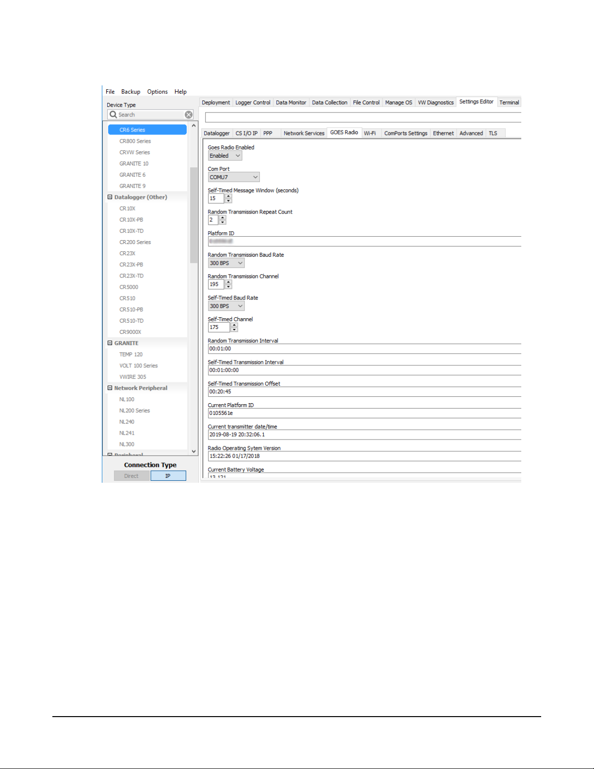
4. Click the GOES Radio sub tab (FIGURE 4-1 (p. 3)).
FIGURE 4-1. Device Configuration Utility GOES Radio screen
5. Select Enabled from the Goes Radio Enabled field.
6. Select the Com Port to which the GOES radio is connected.
7. Type the Self-timed Message Windows (in seconds) as assigned by GOES DCS Program.
8. Type the Platform ID (in HEX) as assigned by the GOES DCS Program.
9. Select the Random Transmission Baud Rate as assigned by the GOES DCS Program.
10. Type the Random Transmission Channel as assigned by the GOES DCS Program.
11. Select the Self-Time Baud Rate as assigned by the GOES DCS Program.
TX325 Satellite Transmitter for GOES V2 3
12. Type the Self-Time Channel as assigned by the GOES DCS Program.
13. Type the Random Transmission Interval as assigned by the GOES DCS Program. Format is
hh:mm:ss.
14. Type the Self-timed Transmission Interval as assigned by the GOES DCS Program. Format is
dd:mm:hh:ss.
15. Type the Self-timed Transmission Offset as assigned by the GOES DCS Program. Format is
hh:mm:ss.
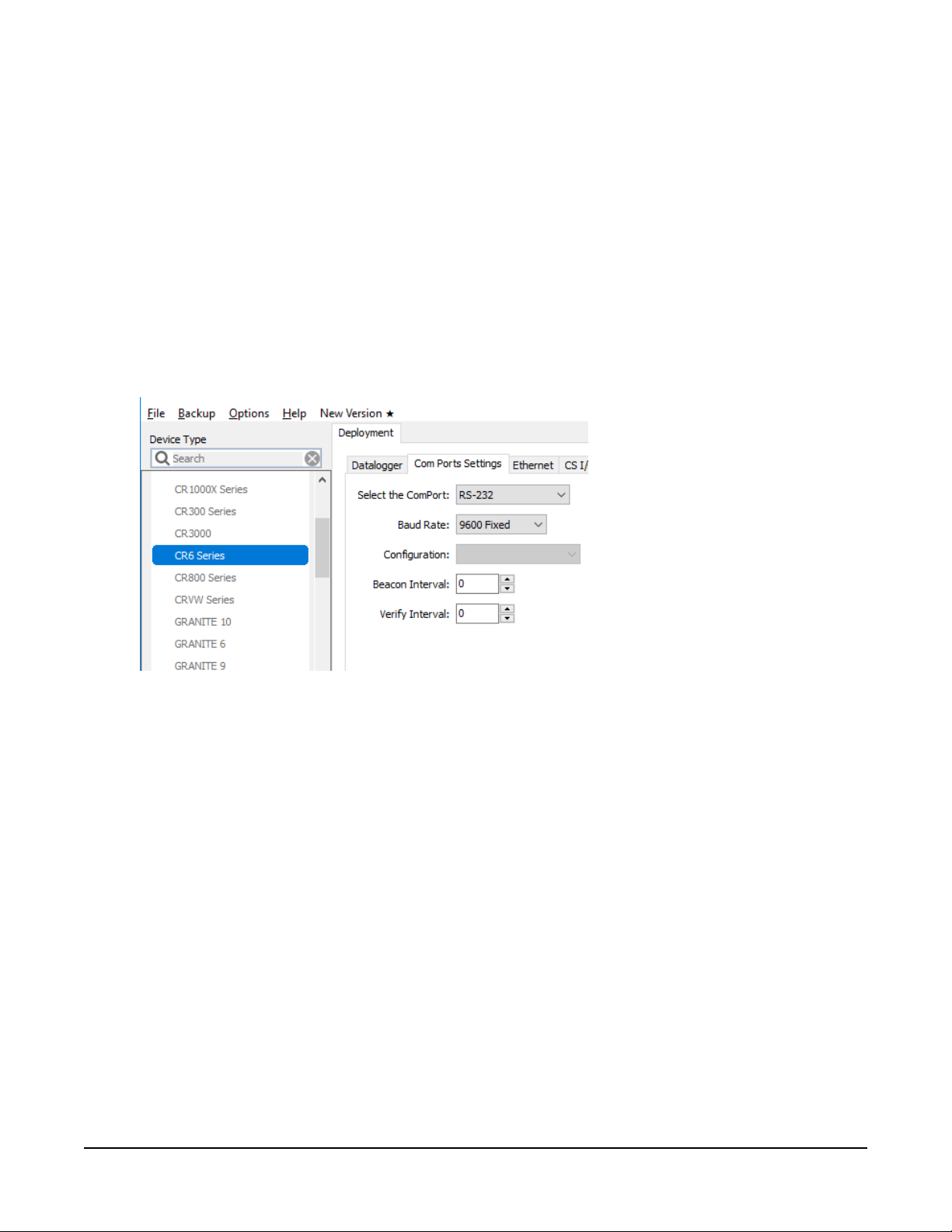
16. Click the Deployment tab.
17. Click the Com Port Settings sub tab.
18. Select 9600 for the Baud Rate.
19. Click Apply to save the changes.
Now the settings are stored in the data logger. CRBasic programming is required to push data
over the network. The GOESTable() and GOESField() CRBasic instructions used in
conjunction with DataTable() facilitate the transmission of data across the GOES satellite
network.
4.1 Data collection platform (DCP) installation
1. Yagi antenna installation procedure:
a. Mount the Yagi antenna to a pole or mast by using the U-bolts included with the
antenna mount.
TX325 Satellite Transmitter for GOES V2 4
b. Attach elements to boom.
NOTE:
When attaching elements to the boom, make sure to place them such that the
number of grooves on the element equals the number of dimples on the boom.
For example, the element with four grooves should be placed at the spot on the
boom with four dimples, and so forth.
c. Aim the Yagi antenna at the spacecraft; azimuth and elevation angle positions are
included on the bracket label.
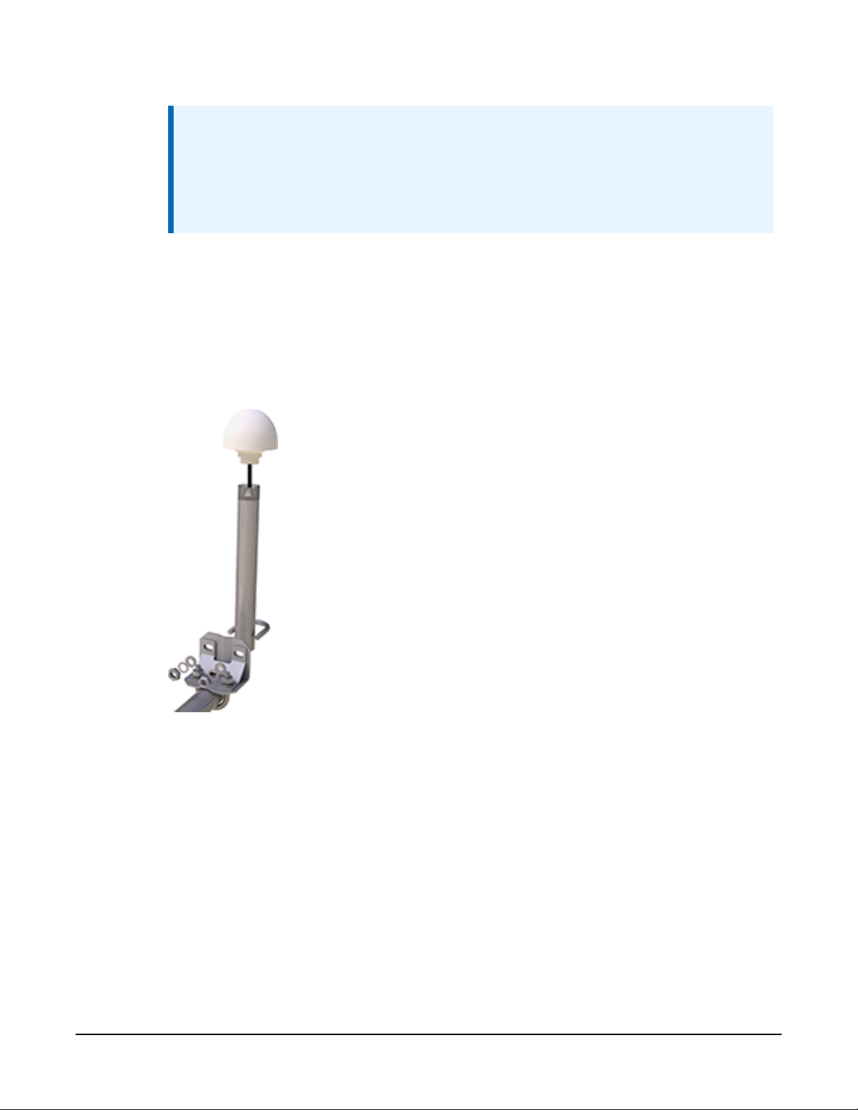
2. GPS antenna installation procedure:
a. Connect the GPS cable to the GPS antenna.
b. Route the cable through the 0.75-inch IPS threaded pipe and insert the pipe into the
GPS antenna.
TX325 Satellite Transmitter for GOES V2 5
 Loading...