

Page 1

INSTRUCTION MANUAL
T.Weather 106 Weather Station
Revision: 9/02
Copyright (c) 1993-2002
Campbell Scientific, Inc.
Page 2

Warranty and Assistance
The T.WEATHER 106 WEATHER STATION is warranted by
CAMPBELL SCIENTIFIC, INC. to be free from defects in materials and
workmanship under normal use and service for twelve (12) months from date
of shipment unless specified otherwise. Batteries have no warranty.
CAMPBELL SCIENTIFIC, INC.'s obligation under this warranty is limited to
repairing or replacing (at CAMPBELL SCIENTIFIC, INC.'s option) defective
products. The customer shall assume all costs of removing, reinstalling, and
shipping defective products to CAMPBELL SCIENTIFIC, INC. CAMPBELL
SCIENTIFIC, INC. will return such products by surface carrier prepaid. This
warranty shall not apply to any CAMPBELL SCIENTIFIC, INC. products
which have been subjected to modification, misuse, neglect, accidents of
nature, or shipping damage. This warranty is in lieu of all other warranties,
expressed or implied, including warranties of merchantability or fitness for a
particular purpose. CAMPBELL SCIENTIFIC, INC. is not liable for special,
indirect, incidental, or consequential damages.
Products may not be returned without prior authorization. The following
act information is for US and International customers residing in countries
cont
served by Campbell Scientific, Inc. directly. Affiliate companies handle
repairs for customers within their territories. Please visit
www.campbellsci.com to determine which Campbell Scientific company
serves your country. To obtain a Returned Materials Authorization (RMA),
contact CAMPBELL SCIENTIFIC, INC., phone (435) 753-2342. After an
applications engineer determines the nature of the problem, an RMA number
will be issued. Please write this number clearly on the outside of the shipping
container. CAMPBELL SCIENTIFIC's shipping address is:
CAMPBELL SCIENTIFIC, INC.
RMA#_____
815 W
Logan, Ut
CAMPBELL SCIENTIFIC, INC. does not accept collect calls.
est 1800 North
ah 84321-1784
Page 3

T.Weather 106 Weather Station
Table of Contents
PDF viewers note: These page numbers refer to the printed version of this document. Use
the Adobe Acrobat® bookmarks tab for links to specific sections.
1. Preparation and Siting .............................................1-1
1.1 Installation Tasks.................................................................................. 1-1
1.2 Tools Required ..................................................................................... 1-1
1.3 Siting and Exposure.............................................................................. 1-3
1.4 Determining True North for Wind Vane Orientation........................... 1-4
2. T.Weather 106 Tower Installation............................2-1
2.1 Base Installation.................................................................................... 2-2
2.2 Tower Installation.................................................................................2-3
2.3 Tower Grounding ................................................................................. 2-4
3. T.Weather 106 Instrumentation Installation ...........3-1
3.1 Enclosure, Datalogger, Power Supply.................................................. 3-2
3.2 Sensor Connection................................................................................ 3-4
3.3 Communication and Data Storage Peripherals..................................... 3-5
3.4 Sealing and Desiccating the Enclosure.................................................3-9
4. T.Weather 106 Sensor Arm Installation..................4-1
4.1 Components.......................................................................................... 4-1
4.2 Installation............................................................................................4-1
4.3 Sensor Connection................................................................................ 4-2
4.4 034A Wind Sensor Installation............................................................. 4-2
4.5 RH and Temperature Radiation Shield................................................. 4-3
4.6 Pyranometer.......................................................................................... 4-3
4.7 Sensor Schematics................................................................................ 4-4
5. Maintenance and Troubleshooting .........................5-1
5.1 Maintenance.......................................................................................... 5-1
5.2 Troubleshooting.................................................................................... 5-3
6. Troubleshooting .......................................................6-1
6.1 Tools Required ..................................................................................... 6-1
6.2 What's Inside the Enclosure at the Weather Station ............................. 6-1
6.3 Communication Options.......................................................................6-3
6.4 What's at the Computer......................................................................... 6-3
6.5 Troubleshooting.................................................................................... 6-4
6.6 Communication Problems.....................................................................6-6
6.7 Sensor Problems................................................................................. 6-11
i
Page 4

T.Weather 106 Weather Station Table of Contents
6.8 ToroPro...............................................................................................6-12
Figures
1.3-1 Effect of Structure on Wind Flow .....................................................1-4
1.4-1 Magnetic Declination for the Contiguous United States ...................1-5
1.4-2 Declination Angles East of True North Are Subtracted
from 0 to Get True North..............................................................1-7
1.4-3 Declination Angles West of True North Are Added to 0
to Get True North..........................................................................1-7
2.1-1 T.Weather 106 Tower Base Installation............................................ 2-3
2.2-1 Raising and Grounding the T.Weather 106 Tower............................2-4
3-1 T.Weather 106 Instrumentation Mounted on the ET Tower ................3-1
3.1-1 Rechargeable Power Mounting Connections.....................................3-2
3.1-2 Solar Panel Mounting........................................................................3-2
3.1-3 Mounting and Grounding the T.Weather 106 Enclosure...................3-4
3.2-1 Position of Sensor Bulkhead Connectors ..........................................3-5
3.2-2 Default Sensor Switch Settings .........................................................3-5
3.3-1 Phone Modem Mounting and Connections .......................................3-6
3.3-2 Short-Haul Modem Mounting and Connection.................................3-7
3.3-3 Short-Haul Modem Wiring Diagram................................................. 3-9
3.4-1 Desiccant Installation.......................................................................3-10
4.2-1 T.Weather 106 Sensor Arm Mounting ..............................................4-1
4.4-1 Wind and RH/Temperature Sensor Installation................................. 4-2
4.6-1 Pyranometer Leveling........................................................................4-3
4.7-1 Schematic of HMP45C-LC RH Temperature Probe and
Connector #1.................................................................................4-4
4.7-2 Schematic of 034A-LC Wind Speed and Direction Probe
and Connector #2..........................................................................4-4
4.7-3 Schematic of LI200X-LC Solar Radiation Sensor and
Connector #3.................................................................................4-5
4.7-4 Schematic of TE525-LC Rain Sensor and Connector #5.................. 4-5
6.2-1 Short Haul Modem Mounting and Connection..................................6-2
6.2-2 T.Weather 106 Terminal Blocks and Sensor Switch Settings...........6-2
ii
Page 5

Section 1. Preparation and Siting
These guidelines apply to several Campbell Scientific weather stations.
1.1 Installation Tasks
1.1.1 Indoors
• Immediately upon receipt of your shipment…
⇒ Open shipping cartons.
⇒ Check contents against invoice. Contact CSI immediately about any
shortages.
• Several days prior to the planned installation date…
⇒ Collect tools and site information (Section 1)
⇒ Trial run the tower, assembling as much as possible (Section 2)
⇒ Repackage equipment for transport to the field site
1.1.2 Outdoors
• Locate suitable site (Section 1)
• Prepare tower (Section 2)
• T.Weather 106 Stations:
⇒ Place instrumentation enclosure low on the T.Weather 106 Tower (Section
⇒ Install sensor option (Section 4)
1.2 Tools Required
Tools required to install and maintain a weather station are listed below.
1.2.1 Tools For Tower Installation
All Towers
Shovel
Rake
Open end wrenches: 3/8", 7/16", ½", (2) 9/16"
Magnetic compass
6' Step ladder
3)
⇒ Slide enclosure to top of tower and secure with correct orientation
(Section 3)
1-1
Page 6

Section 1. Preparation and Siting
1.2.2 Tools For Instrumentation And Maintenance
T.Weather 106 Tower
Tape measure (12’ to 20’)
Claw hammer
Level (24” to 36”)
Hand saw
Materials for concrete form:
(4) 1" x 2" x 12" stakes
(2) 2" x 4" x 96" lumber
(12) 8p double-head nails
(8) 16p double-head nails
20 ft form wire
½ Yard concrete
Concrete trowel, edger
Electrical Fish tape or 20 feet of small diameter rope
Wheelbarrow
All Towers
Lock and key for enclosure
Magnetic declination angle (Section 4)
Magnetic compass
Straight bit screwdrivers (small, medium, large)
Phillips-head screwdrivers (small, medium)
Small diagonal side-cuts
Needle-nose pliers
Wire strippers
Pocket knife
Calculator
Volt / Ohm Meter
Electrical Tape
Step ladder (6')
Datalogger prompt sheet (Section 6)
Station manuals
Station log and pen
Open end wrenches: 3/8", 7/16", ½", (2) 9/16"
Socket wrench and 7/16" deep well socket
Adjustable wrench
Pliers
Conduit and associated tools (as required)
Felt-tipped marking pen
Claw hammer
Pipe wrench (12")
1-2
1.2.3 Supplies for Power and Communications Options
AC Power
Wire, conduit, and junction boxes as needed
Phone Modem
Hayes compatible calling modem for PC
Phone line to weather station or junction box
Short-Haul Modem
4 Conductor communications cable from P C to weather station or junction box
6' copper ground rod and clamp for PC surge protection (optional)
Page 7

1.3 Siting and Exposure
Section 1. Preparation and Siting
CAUTION
If any part of the weather station comes in contact with
power lines, you could be killed. Contact local utilities for
the location of buried utility lines before digging or driving
ground rods.
Selecting an appropriate site for the weather station is critical in order to obtain
accurate meteorological data. In general, the site should be representative of
the general area of interest, and away from the influence of obstructions such as
buildings and trees.
The weather station should not be located where sprinkler irrigation water will
strike sensors or instr ument enclosure.
Some general guidelines for site selection are listed below, which were
condensed from EPA (1988)
1
, WMO (1983)2, and AASC (1985)3 publications.
1.3.1 Wind Speed and Direction
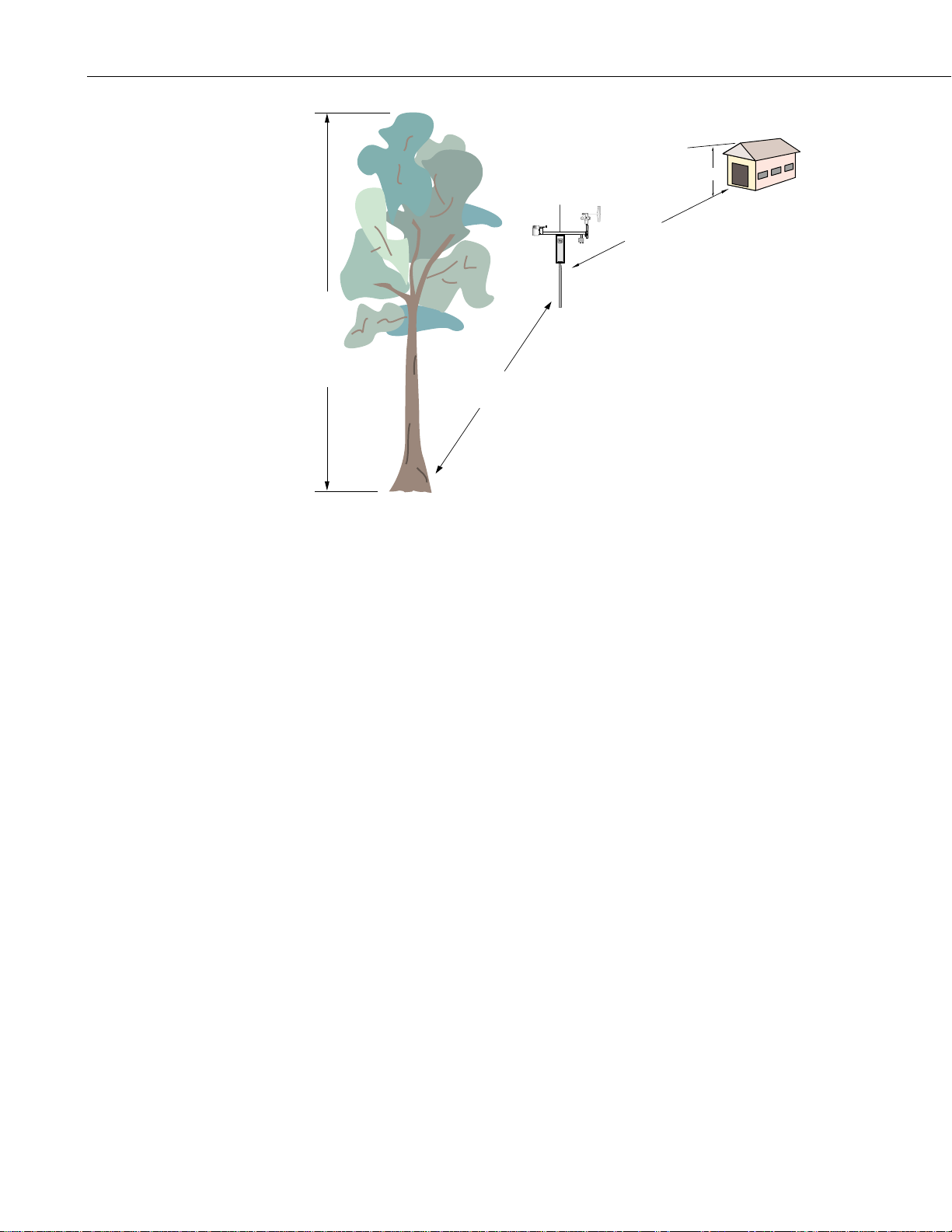
Wind sensors should be located over open level terrain, and at a distance of at
least ten times (EPA) the height of any nearby building, tree or other
obstruction, as illustrated in Figure 1.3-1.
1.3.2 Temperature and Relative Humidity
Sensors should be located over an open level area at least 9 m (EPA) in
diameter. The surface should be covered by short grass, or where grass does
not grow, the natural earth surface. Sensors should be located at a distance of
at least four times the height of any nearby obstruction and at least 30 m (EPA)
from large paved areas. Sensors should be protected from thermal radiation,
and adequately ventilated.
Situations to avoid include:
• large industrial heat sources
• rooftops
• steep slopes
• sheltered hollows
• high vegetation
• shaded areas
• swamps
• areas where snow drifts occur
• low places holding standing water after rains
1-3
Page 8
Section 1. Preparation and Siting
Height of tree (T)
10T
H
10H
Logan, Utah
MADE IN USA
FIGURE 1.3-1. Effect of Structure on Wind Flow
1.4 Determining True North for Wind Vane Orientation
Magnetic declination, or other methods to find True North, should be determined
prior to installing the weather station. True North is usually found by reading a
magnetic compass and applying the correction for magnetic declination*; where
magnetic declination is the number of degrees between True North and Magnetic
North. Magnetic declination for a specific site can be obtained from a USFA map,
local airport, or through a computer service offered b y the USFS called GEOMAG
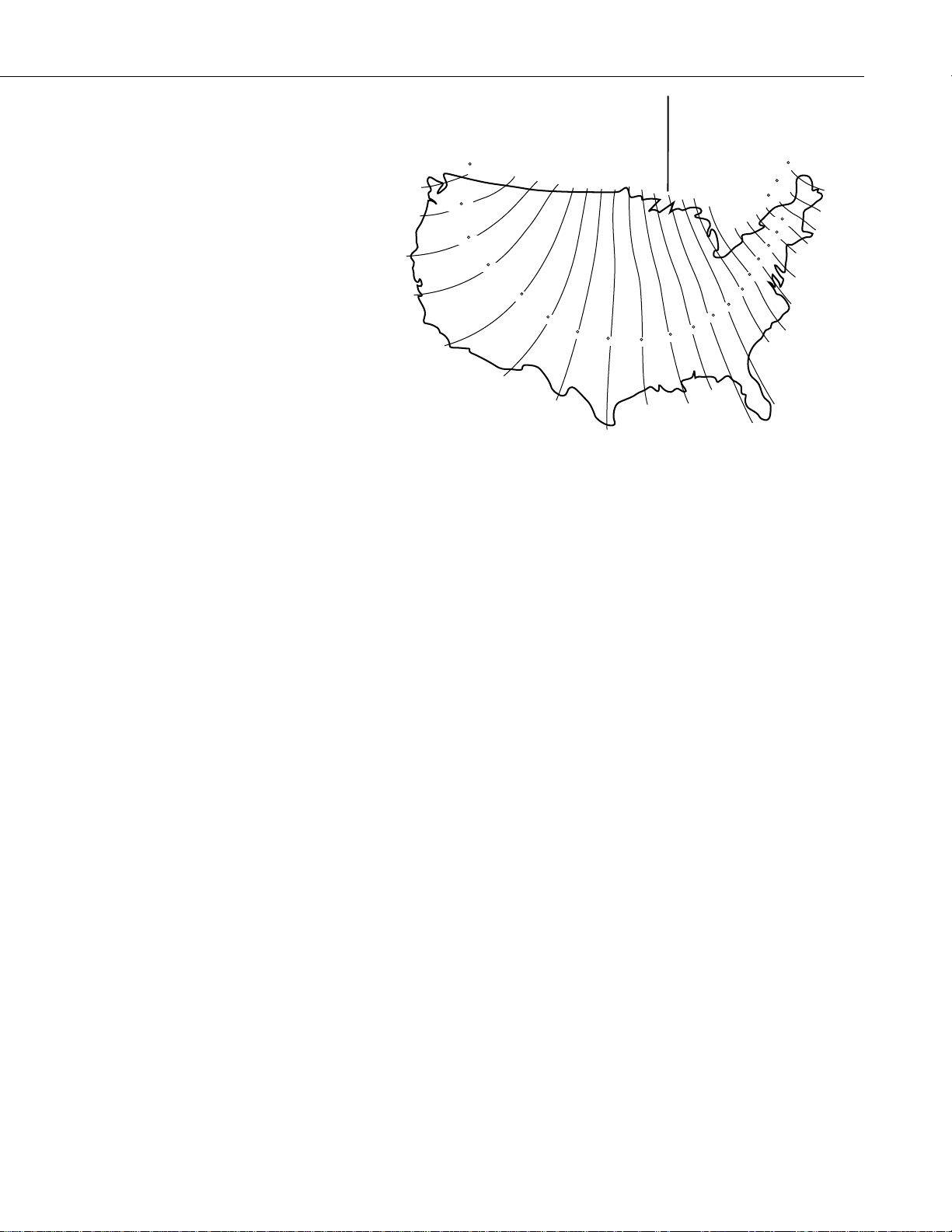
(Section 1.4.1). A general map showing magnetic declination for t he contiguous
United States is shown in Figure 1.4-1.
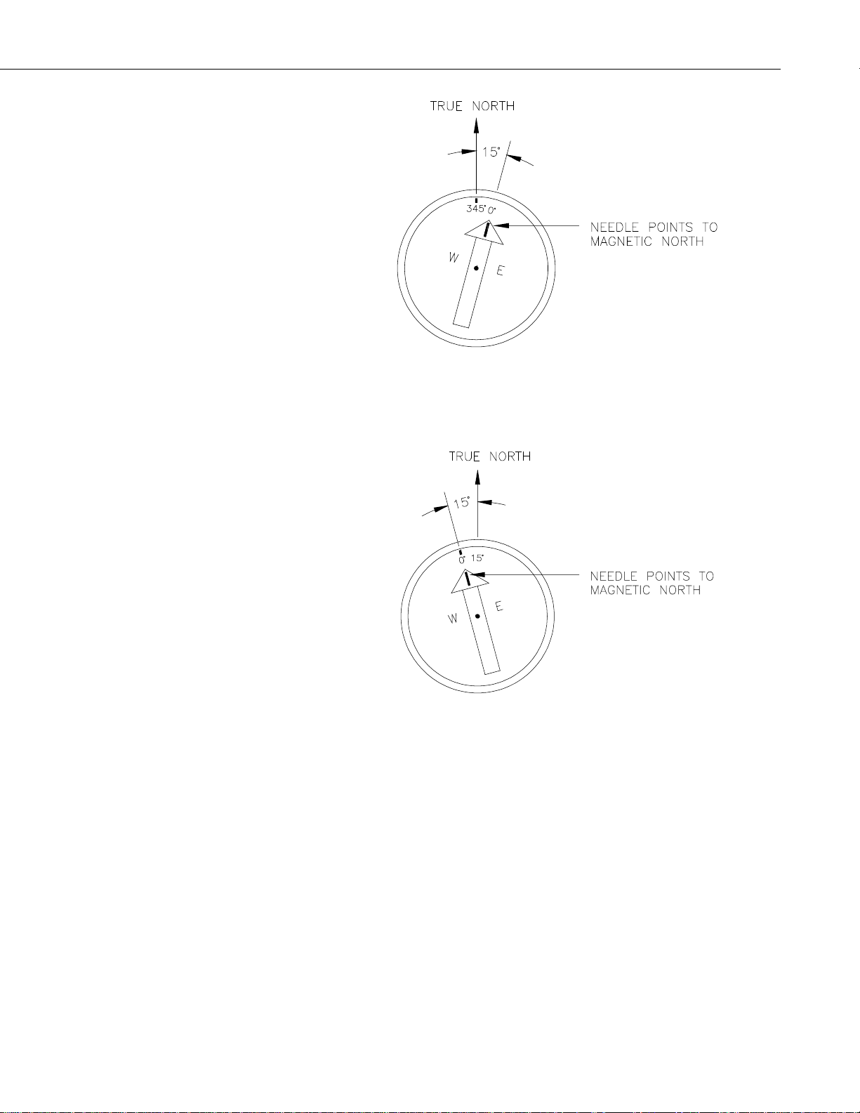
Declination angles east of True North are considered negative, and are subtracted
from 0 degrees t o get True North as shown Figure 1.4-2. Declination angles west
of True North are con-sidered positive, and are added to 0 degrees to get True
North as shown in Figure 1.4-3. For example, the declination for Logan, Utah is
16° East. True North is 360° - 16°, or 344° as read on a compass.
* Other methods employ observations using the North Star or the sun, and are
discussed in the Quality Assurance Handbook for Air Pollution
Measurement Systems, Volume IV - Meteorological Measurements
4
.
1-4
Page 9
Section 1. Preparation and Siting
Subtract declination from 360° Add declination to 0°
22 E
20 E
18 E
16 E
FIGURE 1.4-1. Magnetic Declination for the Contiguous United States
1.4.1 Prompts from GEOMAG
GEOMAG is accessed by phone with a PC and telephone modem, and a
communications program such as GraphTerm (PC208 Software). GEOMAG
prompts the caller for site latitude, longitude, and elevation, which it uses to
determine the magneti c declination and annual change. The following
information, menu, and prompts are from GEOMAG:
14 E
12 E
10 E
8 E
6 E
4 E
2 E
20 W
18 W
16 W
14 W
12 W
10 W
8 W
6 W
4 W
2 W
0
GEOMAG is a user-friendly program that provides estimates of the
geomagnetic field elements, including declination and total field intensity,
based upon Magnetic Models. The program is accessible by modem.
Modem Access:
Modem settings: No parity, 8 data bits, and 1 stop bit (i.e., N81)
Telephone numbers:
Phone Number Baud Rates
303-273-8672 2400
303-273-8673 1200
303-273-8678 1200
Upon carrier-signal detection, press Return once or twice.
If you are using one of the commercial numbers, the following prompts will
appear. Type the responses shown (followed by pressing RETURN):
GLDSV1> c neis [RETURN]
Username: QED [RETURN]
1-5
Page 10

Section 1. Preparation and Siting
MAIN MENU
Type
Q for Quick Epicenter Determinations (QED)
L for Earthquake Lists (EQLIST)
M for Geomagnetic Field Values (GEOMAG)
X to log out
Enter program option: M
Would you like information on how to run GEOMAG (Y/N)? N
Options:
1 = Field Values (D, I, H, X, Z, F)
2 = Magnetic Pole Positions
3 = Dipole Axis and Magnitude
4 = Magnetic Center [1] : 1
Display values twice [N]: press return
Name of field model [USCON90]: press return
Date
[current date]: press return
Latitude : 42/2 N
Longitude : 111/51/2 W
Elevation : 4454 ft
Example of report generated by GEOMAG:
Model: USCON90 Latitude: 42/2 N
Date : 7/27/93 Longitude: 111/51/2 W
Elevation: 4454.0 ft
D
deg min
15 59.6
Annual change:
0 -6.1
Exiting:
Press "Cntrl-Z" to exit GEOMAG.
When the main menu reappears either select another option or type "X" to
log out.
If you used one of the commercial numbers, the GLDSV1> prompt will
reappear.
Type "LO" to disconnect.
Use of GEOMAG is free (except for telephone charges). If possible, please
avoid using
1-6
GEOMAG between 9 a.m. and 4 p.m., mountain time, Mond ay through Friday.
The declination in the example above is listed as 15 degrees and 59.6 minutes.
Expressed in degrees, this would be 15.99 degrees. As shown in Figure 1.4-1,
the declination for Utah is east, so True North for this site is 360 - 15.99, or
344 degrees. The annual change is -6.1 minutes.
Page 11
Section 1. Preparation and Siting
FIGURE 1.4-2. Declination Angles East of True North Are
Subtracted From 0 to Get True North
FIGURE 1.4-3. Declination Angles West of True North Are
Added to 0 to Get True North
1-7
Page 12

Section 1. Preparation and Siting
This is a blank page.
1-8
Page 13
Section 2. T.Weather 106 Tower Installation
DANGER: Do not install near power lines. If any part of the tower comes in contact with
power lines you could be KILLED. Contact local utilities for the location of buried utility
lines before digging or driving grounding rods.
CAUTION: Do not fit the 3 meter T.Weather 106 Tower sections together until the
appropriate time. Once attached, they cannot be detached.
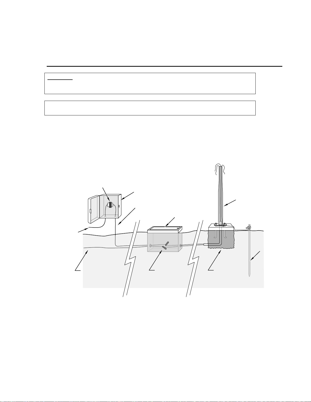
The T.Weather 106 Tower provides a support structure for mounting the T.Weather 106
weather station components. Figure 2.1-1 shows a typical T.Weather 106 Tower
installation option. The tower is designed to withstand winds of 100 mph. The lightning
rod assembly is attached after the instrumentation enclosure is installed (Section 3.1).
110 VAC
Transformer
Communications
Line
FIGURE 2.1-1. T.Weather 106 Tower Installation
User Supplied
Junction Box
16 VAC
Power
Direct Bury
Splices
ET Tower
Valve Box
Ground
Rod
Concrete
Base
2-1
Page 14

Section 2. T.Weather 106 Tower Installation
2.1 Base Installation
2.1.1 Supplied Components
(3) 1/2 inch L-Bolts
(9) 1/2 inch Nuts
(1) Anchor Template
Refer to Section 1 for components supplied by installer.
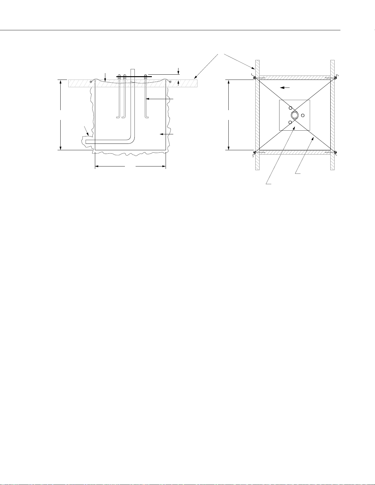
2.1.2 Installation
1. The T.Weather 106 Tower attaches to a user supplied concrete foundation
constructed as shown in Figure 2.1-1.
2. Construct the concrete form with 2" x 4" lumber and 16p nails.
3. Assemble the template and anchor bolts. There should be two nuts below
and one nut above the template on each bolt.
4. Clear an area large enough to set the form at the desired elevation.
5. Dig a hole 2 feet x 2 feet x 2 feet. Lighter soils may require a deeper hole.
About 20 inches below the top of the hole, gouge a small cavity in one wall
of the hole. The cavity should be about 4 inches deep and just large
enough in diameter t o insert one end of the conduit. Make certain t he
cavity "points" in the direction from which power and communications
cables will come.
6. Center the form over the hole. Adjacent to the form, drive four stakes into
the soil. Secure the leveled form to the stakes with the 8p nails.
7. Cap the ends of the conduit with duct tape. Position the conduit and wire
into place by securing the wire to nails in the form.
8. Fill the hole and form with approximately ½ yard of concrete. Screed the
concrete level with the top of the form. Center the template assembly over
the conduit and press into the concrete. Put 2 x 4 spacers between the
template and the top of the form. The bottom of the bolt threads should be
about ½ inch above the concrete. The template must be level in two
dimensions. Use a trowel and edger to finish.
9. Wait 24 hours before removing the concrete form. Wait 7 days before
mounting the T.Weather 106 Tower.
2-2
Page 15
Section 2. T.Weather 106 Tower Installation
24"
SMALL
CAVITY
FORM WIRE
SIDE VIEW
2"
ANCHOR BOLT
CEMENT PAD
24"
FORM
24"
FIGURE 2.1-1. T.Weather 106 Tower Base Installation
TOP VIEW
NORTH
FORM WIRE
TEMPLATE
2.2 Tower Installation
2.2.1 Supplied Components
(1) Upper Tower Section (Tapered)
(1) Lower Tower Section
(6) 1/2 inch Washers
(1) 12 foot 12 AWG Ground Cable
(1) Tower Cap
(1) 20' communications cable
(1) 20' power cable
Refer to Section 1 for components supplied by installer.
2.2.2 Installation
Attach the tower to the base as shown in Figure 2.2-1.
1. Dig a hole close to the concrete base to access the lower conduit opening.
From the hole, trench to the power and communications sources. Remove
the duct tape from both ends of the conduit.
2. Remove the template. Attach the two pieces of the tower. This is a
permanent connection and cannot be undone. Lay the tower on the ground
with the base next to the concrete foundation.
3. Thread communications and power cables through the tower and conduit.
Electrical fish tape will help.
2-3
Page 16
Section 2. T.Weather 106 Tower Installation
4. Cut and save a 9-inch piece of 12 AWG ground wire from the 12-foot
length provid ed. Thread the remaining 11 foot ground wire through the
tower. Secure all wiring so it does not slip back into the tower or conduit.
5. Place the tower cap over the tower end.
6. Raise the tower on a still day. Place a washer on top of the two nuts on
each foundation bolt. Taking great care not to damage cables between the
tower and conduit, raise the tower and lower it onto the conduit and
mounting bolts. Install a washer and nut on each bolt and hand tighten.
Check plumb of the tower by placing a level on the north and east sides of
the lower tower section. Adjust the topmost of the two lower nuts (leveling
nut) on each bolt as necessary. When plumb is established, lock the
leveling nut in place by tightening the lowest nut against it. Tighten the
three top nuts with the wrench.
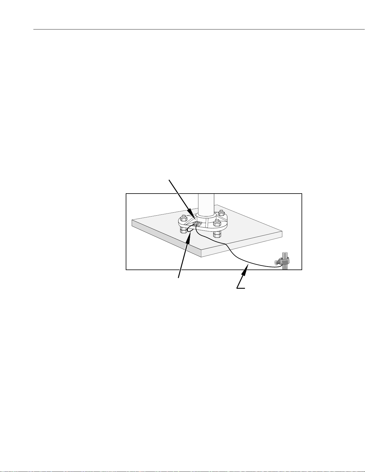
Ground Lug
FIGURE 2.2-1. Raising and Grounding the T.Weather 106 Tower
2.3 Tower Grounding
2.3.1 Supplied Components
(1) 5 foot 4 AWG Ground Cable
(1) Copper Ground Lug, Bolt
(1) Ground Rod, Clamp
Refer to Section 1 for components supplied by installer.
2-4
12AWG Wire
4AWG Cable
Page 17

2.3.2 Grounding Procedure
Ground the tower as shown in Figure 2.2-1.
1. Place the ground rod clamp on the rod. Secure it about 3 inches from the
top. Do this before the rod is driven into the ground. Be careful not to
damage the clamp with the hammer
2. Taking care not to damage power or communications lines, drive the
ground rod close to the foundation using a fence post driver or sledge
hammer. Drive the rod at an angle if an impenetrable hardpan layer exists.
Soften hard clay soils with water if necessary.
3. Strip 1 inch of insulation from both ends of the 4 AWG ground cable.
Strip 1 inch of insulation from the lower end of the 14 AWG ground wire.
Install the tower grounding lug to the tower base with the 7/16 bolt
provided (Figure 2.2-1). Loosen the lug's set screw and insert the 4 AWG
and 14 AWG wire. Tighten the set screw.
4. Loosen the ground rod clamp. Insert the 4 AWG wire. Tighten the clamp
(Figure 2.2-1).
Section 2. T.Weather 106 Tower Installation
2-5
Page 18

Section 2. T.Weather 106 Tower Installation
This is a blank page.
2-6
Page 19

Section 3. T.Weather 106 Instrumentation Installation
The weather station datalogger, power supply, sensor connection panel, communications
devices, and data retrieval peripherals are mounted in the T.Weather 106 enclosure at the
locations shown in Figure 3-1. Components include:
(1) T.Weather 106 Enclosure
(1) 4 unit Desiccant Pack
(1) Flat Point Screw Driver
(1) Phillips Screwdriver
(1) Power Supply Option
(1) Telecommunications Option
(1) 9-inch piece of 12 AWG ground wire
(1) Lightning rod and clamp
Logan, Utah
MADE IN USA
T.Weather 106
FIGURE 3-1. T.Weather 106 Instrumentation Mounted on the ET Tower
3-1
Page 20

Section 3. T.Weather 106 Instrumentation Installation
3.1 Enclosure, Datalogger, Power Supply
3.1.1 Battery Option Installation
Solar Panel or 16 VAC
Power Cable
FIGURE 3.1-1. Rechargeable Power Mounting and Connections
YUASA
a) Sealed Rechargeable Battery Option: Install the kit as shown in Figure
3.1-1. An unregulated solar panel or 17 to 24 VAC must be used with the
rechargeable battery at all times. In either case, power is routed through
the Heyco fitting on the enclosure back and connected to the CHG ports by
depressing co nnector levers. Pol arity of the CHG connection d oes not
matter. Install the rechargeable battery and plug the battery lead into the
connector labeled “LA”.
NOTE
Press the connector levers gently or they might break.
3.1.2 Solar Panel Installation
3-2
FIGURE 3.1-2. Solar Panel Mounting
Page 21

Section 3. T.Weather 106 Instrumentation Installation
a) Mount the solar panel to the tower using the mounting brackets as shown
in Figure 3.1-2. Mount the solar panel to the tower so it faces south
(northern hemisphere). Position it as high off the ground as practical,
ensuring it cannot interfere with air flow or sunlight around the sensors.
The solar panel should be oriented to receive maximum insolation over the
course of the year. Suggeste d tilt angles (referenced to the ho rizontal
plane) are listed below.
Site Latitude Tilt Angle
0 to 10 degrees 10 degrees
11 to 20 Latitude + 5 degrees
21 to 45 Latitude + 10 degrees
46 to 65 Latitude + 15 degrees
>65 80 degrees
b) After determining the tilt angle, loosen the two bolts that attach the
mounting bracket to the panel. Adjust the angle, then tighten the bolts.
Secure the lead wire to the mast using wire ties. Make electrical
connections as described in 3.1.1a above.
3.1.3 AC Power Installation
a) The AC power option includes a 120 VAC to 16 VAC. The transformer
should be mounted inside a user supplied junction box according to local
electrical codes. Dangerous electrical accidents may be avoided by
locating the transformer remotely and burying a low voltage line to the
station. The low voltage will carry up to 500 feet on an 18 AWG power
cable.
b) Shut off 110 VAC power at the main breaker. Connect the primary leads
of the transformer to 110 VAC following instructions provided with the
transformer. Connect a two conductor cable to the secondary terminals of
the transformer. Route the cable from the transformer to the T.Weather
106 Enclosure according to local electrical codes.
3.1.4 Enclosure Installation
1. Mount and ground the T.Weather 106 enclosure on the T.Weather 106
Tower as shown in Figure 3.1-3.
a) Place the enclosure low on the tower. Do not tighten clamps.
b) Install the sensor arm (T.Weather 106) as described in Section 4.
3-3
Page 22

Section 3. T.Weather 106 Instrumentation Installation
FIGURE 3.1-3. Mounting and Grounding the T.Weather 106 Enclosure
c) Slide the enclosure to the top of the T.Weather 106 tower. Position it
on the north side of the tower (northern hemisphere). The top of the
enclosure should be flush with the top of the tower, with the width of
the sensor arm extending above the tower. Tighten the clamps until
the enclosure is snug. Do not over-tighten since doing so may
damage the tower or enclosure.
9-inch
Ground
Wire
NORTH
Tower
Ground
Wire
d) Carefully mount the lightning rod and clamp to the top of the
T.Weather 106 Tower. Clearance between the clamp and the
enclosure is minimal. Care should be taken not to scratch the
enclosure or sensor assembly. Strip 1 inch of insulation from the top
end of the 12 AWG green tower ground wire, curl the end and place
the curled end under the head of one of the lightning rod clamp bolts.
Tighten the bolt.
e) Strip 1 inch of insulation from each end of the 9 inch piece of 12
AWG ground wire. I nsert one end into the brass ground lug located
at the top back of the enclosure. Curl the other end and place under
the head of one of the lightning rod clamp bolts. Tighten the bolt.
3.2 Sensor Connection
1) Install the sensor set as described in Section 4.
2) Remove the protective connector cover from the back of the T.Weather
106 Enclosure by removing the two Phillips head screws. Sensors connect
to one of seven labeled bulkhead connectors as shown in Figure 3.2-1.
3-4
Page 23

Section 3. T.Weather 106 Instrumentation Installation
Earth
Ground
#2
#6
#7
#5
#1
#3
#8
Stand off
TEMP
CS615
WS/WD
SDI 12
GYP BLOCK
TEMP
RAIN
(PRECIP)
TEMP / RH
SOLAR
RADIATION
COMM
CS I/O
POWER CABLE PORT
STAND OFF
COAXIAL CONNECTION
Connector#4Sensors
FIGURE 3.2-1. Position of Sensor Bulkhead Connectors
3) Replace the protective connector cover after sensors are connected and
power and communications cables are installed. Ensure that all cables and
connector caps are under the cover before tightening the screws.
4) Configure senso r switch settings as shown in Figure 3.2-2 if necessary.
604 Ohm
Open
100 Ohm
1 K
Open
(LI190SB)
(LI1200X)
(LI200S)
(HMP35C)
(CS500, HMP45C)
Open
SW 12V
Open
(CS500, HMP45C)
(HMP35C)
5V
FIGURE 3.2-2. Default Sensor Switch Settings
3.3 Communication and Data Storage Peripherals
One communications kit can be mounted to the T.Weather 106 Enclosure back
plate. Communication kits ordered with the T.Weather 106 Enclosure are premounted and pre-wired; no further connections inside the enclosure are
3-5
Page 24

Section 3. T.Weather 106 Instrumentation Installation
necessary. Follow the "External Installation" procedures outlined below to
make the external connections.
If you received a telecommunications kit separate from the T.Weather 106
Enclosure, follow the "Internal Installation" procedures outlined below.
3.3.1 Phone Modems
Phone modems enable communications between the T.Weather 106 Enclosure
and a Hayes compatible modem in your PC over a dedicated phone line. Phone
line surge protection in built into the T.Weather 106 Enclosure.
P/N 10588 Cable
FIGURE 3.3-1. Phone Modem Mounting and Connections
3.3.1.1 Internal Installation
For installation inside the T.Weather 106 Enclosure, the following components
are provided in the phone modem kit:
(1) COM200 or COM300 Phone Modem
(1) 12 inch RJ-11 Patch Cord
(1) Mounting Bracket
(4) Screws
(1) 12 inch 14 AWG Ground Wire
Install the phone modem as shown in Figure 3.3-1.
1. Attach the modem to the modem bracket with the 4 screws provided.
Mount the modem and bracket into the T.Weather 106 Enclosure with the
3 pre-threaded screws on the mounting plate.
2. Connect the modem 9-pin port to the T.Weather 106 Enclosure port with
the P/N 10588 ribbon cable supplied with the T.Weather 106 Enclosure.
RJ11 Patch
Cord
Ground
Wire
Modem
3-6
3. Connect the modem RJ-ll jack to the T.Weather 106 Enclosure RJ-11 jack
with the RJ-ll patch cord.
Page 25

4. Connect the modem ground port to the T.Weather 106 Enclosure ground
with the 14 AWG ground wire.
3.3.1.2 External Installation
The following modem kit components are used to make the external
connections:
(1) Direct Burial Splice Kit
(1) 20 foot Telephone Patch Cord with Connector
1) Connect the 20 foot patch cord to the connector marked "comm" on the
external back panel, under the protective cover.
2) Splice the labeled "Tip" and "Ring" lines of the patch cord to the telephone
service line. Use the direct burial splice kit when splices are in a valve
box or buried.
3.3.2 Short-Haul Modem
Short-haul modems enable communication between a datalogger and computer
over two twisted pairs of wires. The maximum distance between modems is
determined by baud rate and wire gauge. At 9600 baud, the approximate range
is 4.0 miles. DCE / DTE switches on the modems are set to DCE.
Section 3. T.Weather 106 Instrumentation Installation
FIGURE 3.3-2. Short-Haul Modem Mounting and Connection
3.3.2.1 Internal Installation
For installation inside the T.Weather 106 Enclosure, the following components
are provided in the short-haul modem kit:
(1) SC932C Interface
(1) Rad Modem
(1) Rad/SC932C Mounting Bracket
(4) Screws
(1) 12 inch 4-wire patch cable
Install the short-haul modems as shown in Figure 3.3-2 and 3.3-3.
QC
CAMPBELL
SCIENTIFIC LTD
SC932 - S/N E1055
3-7
Page 26

Section 3. T.Weather 106 Instrumentation Installation
1. Mount the Rad / SC932C mounting bracket into the T.Weather 106
Enclosure with the 3 pre-threaded screws provided.
2. Connect the Rad Modem and SC932C. Strap them into the mounting
bracket under the Velcro strap.
3. Connect the SC932C 9-pin port to the internal T.Weather 106 Enclosure 9pin port with the blue ribbon cable provided.
4. Wire the Rad Modem to the T.Weather 106 Enclosure with the 12 inch
patch cord. Match wire labels to wiring panel labels on both the
T.Weather 106 Enclosure and the Rad Modem (+XMT to +XMT, etc.). A
small screw driver in provided with the T.Weather 106 Enclosure to access
the Rad Modem connections.
3.3.2.2 External Installation
The following short-haul kit components are used to make the external
connections:
At the T.Weather 106 Enclosure:
(1) 20 foot 4-Wire Patch Cable
(2) 2 Direct Burial Splice Kits
(1) Length of User Supplied Wire (Supplier: Anixter, p/n F-02P22BPN,
Phone 847-677-2600)
At the PC :
(1) Rad Modem
(1) 5 foot 4-wire Patch Cable
(1) 10 foot 14 AWG Ground Wire
(1) Surge Protector and Case
1) Connect the 20 foot patch cable to the connector marked "comm" on the
external back panel of the T.Weather 106 Enclosure. Splice this cable to
the user supplied cable, using the direct burial splice kits.
2) Mount the surge protector to a flat surface near the PC's serial port.
Ground the center terminal to an earth (or building) ground using the 14
AWG wire.
3) Connect the 5 foot patch cord to the Rad Modem. Fasten the cable to the
strain relief tab with a cable tie. Connect the Rad to the PC's serial port
either dire ctly (25 pin port) or through a 9 to 25 pin serial converter .
4) Route the user-supplied cable from the remote splice to the surge protector.
Connect it and the 5 foot patch cord to the surge protector.
3-8
Page 27

Section 3. T.Weather 106 Instrumentation Installation
PC
SRM-5A
- RCV (white)
+ RCV (green)
- XMT (black)
+ XMT (red)
+ RCV (red)
- RCV (black)
+ XMT (green)
- XMT (white)
ET106 ENCLOSURE
Surge
+ RCV (red)
- RCV (black)
+ XMT (green)
- XMT (white)
Protector
Earth Ground
Supplied
1
2
3
4
User
Cable
Splices
1
2
3
4
+ RCV
- RCV
+ XMT
- XMT
QC
SC932 - S/N E1055
BLACK
GREEN
WHITE
SCIENTIFIC LTD
RED
CAMPBELL
ET106 ENCLOSURE
To # 8
External Connector
FIGURE 3.3-3. Short-Haul Modem Wiring Diagram
3.4 Sealing and Desiccating the Enclosure
The T.Weather 106 Enclosure is supplied with a desiccant pack. The desiccant
maintains a low humidity in the enclosure to minimize the chance of
condensation on the instrumentation. Desiccant should be changed when the
internal T.Weather 106 Enclosure humidity sensor measures 30% or higher.
Install the desiccant as shown in Figure 3.4-1. Keep unused desiccant tightly
sealed in an airtight container.
1) Take the desiccant pack out of its sealed plastic bag. Place it under the
desiccant strap just before leaving the station.
2) Be sure to close the enclosure hasp securely. A padlock may be used on
the latch for extra security.
3-9
Page 28

Section 3. T.Weather 106 Instrumentation Installation
k
DO NOT EAT
UNITED DESICCANTS-GATES
101CHRISTINE, BELEN, NEW MEXICO 87002
DESI PAK
SPECIFICATION MIL-D-3464 TYPE I &II
REACTIVATION TIME IN-BAG 16 HOURS AT 250 F
DESICCANT
CONTENTS
PACKAGE U
ACTIVATED
4
BAGGED FOR
UNITS
DEHUMIDIFICATIO
DO NOT EAT
UNITED DESICCANTS-GATES
101CHRISTINE, BELEN, NEW MEXICO 87002
DESI PAK
SPECIFICATION MIL-D-3464 TYPE I &II
REACTIVATION TIME IN-BAG 16 HOURS AT 250 F
DESICCANT
CONTENTS
PACKAGE USE
ACTIVATED
4
BAGGED FOR
UNITS
DEHUMIDIFICATION
Desiccant
Pac
O
SE
AND STATIC
N
O
AND STATIC
FIGURE 3.4-1. Desiccant Installation
3-10
Page 29

Section 4. T.Weather 106 Sensor Arm Installation
4.1 Components
(1) T.Weather 106 Sensor Arm
(1) Met One 034A Wind Sensor
(1) 034A Mounting Shaft
(1) Radiation Shield
4.2 Installation
Install the T.Weather 106 Sensor Arm after the Enclosure is mounted low on
the Tower. You may need to temporarily remove communications option.
Mount the sensor arm as shown in Figure 4.2-1 without the wind sensor
attached.
ET Sensor
Arm
ET Enclosure
Screws
(4)
FIGURE 4.2-1. T.Weather 106 Sensor Arm Mounting
1) Remove the cover from the Enclosure.
2) Place the sensor arm on top of the enclosure, lining up the four threaded
holes on the under side of the arm with the four holes in the top of the
enclosure. Attach the arm to the enclosure by inserting and tightening four
Phillips head screws. Adjust the position of the Enclosure so that the
sensor arm is oriented along a due east to due west axis.
4-1
Page 30

Section 4. T.Weather 106 Sensor Arm Installation
4.3 Sensor Connection
Refer to Section 3 for sensor connection details.
4.4 034A Wind Sensor Installation
Install the 034A Wind Sensor as shown in Figure 4.4-1 after the sensor arm is
securely installed. The wind vane is oriented after the datalogger has been
programmed (Section 5), and the location of True North has been determined
(Section 1.2). Orientation is most easily done with two people, one to aim and
adjust the sensor, while the other observes the wind direction displayed by
CR10KD Keyboard Display or a laptop PC.
4-2
FIGURE 4.4-1. Wind and RH/Temperature Sensor Installation
1) Place the 034A in the 034A Mounting Shaft pointing the vane due south.
Tighten the alignment screw.
2) Attach the 034A and mounting shaft to the sensor arm. Insert the mounting
shaft into the U-bolt clamp. Adjust sensor height to 2 or 3 meters by
moving the mounting shaft up or down in the clamp. Lightly tighten clamp
nuts.
3) Attach the 034A connector to the 034A.
4) Establ ish a reference poi nt on the horizon for True North.
5) Sighting down the instrument center line, aim the counter weight at True
North.
6) While holding the wind vane position, slowly rotate the sensor base until
the sensor is aligned properly. Securely tighten the clamp nuts.
Page 31

Section 4. T.Weather 106 Sensor Arm Installation
4.5 RH and Temperature Radiation Shield
Mount the radiation shield to the sensor arm as shown in Figure 4.4-1. Remove
yellow cap. Place the RH and temperature assembly inside the shield shaft.
Attach the shield to the sensor arm with the two screws.
4.6 Pyranometer
Level the pyranometer as indicated in Figure 4.6-1. Adjust the three leveling
screws until the bubble level indicates plumb. Remove the red cap from the
pyranometer.
Leveling
Screws
FIGURE 4.6-1. Pyranometer Leveling
Check the measurements of all sensors after the datalogger is programmed.
Display measurements using the *6 Mode with the CR10KD.
Input
Location
1 Enclosure Temperature (°C) Close to air temperature
3 Solar Radiation (kW m
4 Air Temperature (°C) -40° to +50°
5 RH (%) 0 to 100%
6 Wind Speed (mph) 0 to 110 mph
7 Rain Fall (inches) 0 to .2
8 Wind Direction (°) 0 to 359
10 Battery (Volt) 9.6 to 14.0 Volts
12 Air Temperature (°F) -40° to +122°
13 Enclosure RH 0% to 30% when sealed for several
Display and set clock time using the *5 mode with the CR10KD.
Parameter
-2
Normal
Range
) 0 to 1.2 kW m
hours
-2
4-3
Page 32

Section 4. T.Weather 106 Sensor Arm Installation
4.7 Sensor Schematics
Schematics of T.Weather 106 sensors and associated connectors are provided
in Figures 4.7-1, 4.7-2, 4.7-3, and 4.7-4 for help in troubleshooting.
Knowledge of the schematics is not necessary for routine installation and
maintenance.
3
4
2
6
5
1
Air T emperature and
Relative Humidity
Sensor
Relative Humidity (0-1VDC)
Air T emperature (0-1VDC)
Not Used
12V Switched Supply
Analog Ground
Shield
Connector
Pin
1
2
3
4
5
6
Datalogger
1 H
1 L
12VDC Switched
Supply
AG
G
FIGURE 4.7-1. Schematic of HMP45C-LC RH and Temperature Probe
and Connector #1
Wind Speed and Wind Direction
Connector
Pin
10K OHM
Excitation
3
Datalogger
E2
4-4
10K OHM
Potentiometer
Magnetically
Activated Reed
1K OHM
Switch
Wind Direction
Signal Return
Analog Ground
Pulse Wind Speed
Ground
Shield
1
2
4
5
6
2H
AG
P1
3
4
2
6
5
1
G
G
FIGURE 4.7-2. Schematic of 034A-LC Wind Speed and Direction Probe
and Connector #2
Page 33

Solar Radiation
Sensor
Section 4. T.Weather 106 Sensor Arm Installation
3
4
2
6
5
1
Connector
Pin
1
40.2 - 90.2 OHM
Datalogger
3 H
Shield
Not Used
Not Used
Not Used
2
3
4
5
6
3 L
G
FIGURE 4.7-3. Schematic of LI200X-LC Solar Radiation Sensor and
Connector #3
Connector
Tipping Rain Bucket
Not Used
Not Used
Pin
1
2
3
4
2
6
5
1
Not Used
4
Datalogger
Pulse
3
P2
Magnetically
Activated Reed
Switch
Ground
Shield
5
G
6
G
FIGURE 4.7-4. Schematic of TE525-LC Rain Sensor and Connector #5
4-5
Page 34

Section 4. T.Weather 106 Sensor Arm Installation
This is a blank page.
4-6
Page 35

Section 5. Maintenance and Troubleshooting
These guidelines apply to several Campbell Scientific weather stations.
5.1 Maintenance
Proper maintenance of weather station components is essential to obtain
accurate data. Equipment must be in good operating condition, which requires
a program of regular inspection and maintenance. Routine and simple
maintenance can be accomplished by the person in charge of the weather
station. More difficult maintenance such as sensor calibration, sensor
performance testing (i.e., bearing torque), and sensor component replacement,
generally requires a skilled technician, or that the instrument be sent to
Campbell Scientific or the manufacturer.
A station log should be maintained for each weather station that includes serial
numbers, dates that the site was visited, and maintenance that was performed.
5.1.1 Instrumentation Maintenance
The instrumentation requires a minimum of routine maintenance. A few
preventative maintenance steps will optimize battery life and decrease the
chances of datalogger failure.
5.1.2 Batteries
5.1.3 Desiccant
Rechargeable power supplies should be connected to an AC transformer or
unregulated solar panel at all times. Be aware of battery voltage that
consistently decreases over time, which indicates a failure in the charging
circuitry.
Enclosure humidity is monitored in the ET Enclosure systems by an RH chip
incorporated into the connector board. Change the desiccant packs when the
enclosure RH exceeds 35%.
Desiccant may be ordered through Campbell Scientific (DSC 20/4) o r item
#4905.
Desiccant packs inside of the dataloggers do not require replacement under
normal conditions.
5-1
Page 36

Section 5. Maintenance and Troubleshooting
5.1.4 Sensor Maintenance
Sensor maintenance should be performed at regular intervals, depending on the
desired accuracy and the conditions of use. A suggested maintenance schedule is
outlined below.
1 week
• Check the pyranometer for level and contamination. Gently clean, if
needed.
• Visually inspect the wind sensors and radiation shield.
1 month
• Check the rain gage funnel for debris and l evel.
• Do a visual/audio inspection of the anemometer at low wind speeds.
• Check the filter of the temperature/humidity sensor for contamination.
General Maintenance
• An occasional cleaning of the glass on the solar panel will improve its
efficiency.
• Check sensor leads and cables for cracking, deterioration, proper routing,
and strain relief.
• Check the tripod or tower for structural damage, proper alignment, and for
level/plumb.
6 months
• Clean the temperature/humidity sensor.
• Clean the Gill Radiation Shield.
1 year
• Replace anemometer bearings.
• Calibrate the rain gage.
• Calibrate the HMP45C probe.
2 years
• Calibrate the pyranometer (some users suggest yearly).
• Calibrate the HMP45C temperature/humidity sensor.
• Replace the wind vane potentiometer and bearings.
4 - 5 years
5-2
• Replace sensor cables as required.
Rain Gage Calibration Check
1. Secure a metal can that will hold at least one quart of water.
Page 37

2. Punch a very small hole in the bottom of the can.
3. Place the can in the top funnel of the rain gage and pour 16 fluid o unces (1
pint) of water into the can. (A 16 oz. soft drink bottle filled to within 2.5
inches of the to p may be used for a rough fiel d calibration. An exact
volume will allow for a more precise calibration).
4. If it takes less than 45 minutes for this water to run out, the hole in the can
is too large.
5. One hundred tip s plus or minus three tips should occur.
6. Adjusting screws are located on the bottom adjacent to the large center
drain hole. Adjust both screws the same number of turns. Rotation
clockwise increases the number of tips per 16 oz. of water; counter
clockwise rotation decreases the number of tips per 16 oz. of water. One
half turn of both screws causes a 2% to 3% change.
7. Check and re-level the rain gage lid.
5.2 TroubleShooting
5.2.1 No Response Using the Keypad
Section 5. Maintenance and Troubleshooting
Check keypad response after each of the following steps.
A. Make sure the battery has been installed, and the power switch, if any, is
"ON" (Section 6.5).
B. Use a voltmeter to measure the voltage on the 12 V and G terminals; the
voltage must be between 9.6 and 16 VDC.
C. Disconnect any sensor or peripheral wires connected to the 5 V and 12 V
terminals.
D. Disconnect any communications or storage peripherals from the
datalogger.
E. Reset the datalogger by turning the power switch to "OFF", then to "ON"
or disconnect the solar panel or switch off AC power to the station then
disconnect and reconnect the battery. Remember to reconnect the solar
panel or switch on the AC power.
F. If still no response, call Campbell Scientific.
5.2.2 No Response from Datalogger through SC32A or Modem Peripheral
At the datalogger:
A. Make sure the battery has been installed, and the power switch, if any, is
"ON" (Section 6.5).
B. Use a voltmeter to measure the voltage on the 12 V and G terminals; the
voltage must be between 9.6 and 16 V DC.
C. Make sure the datalogger is connected to the modem, and the modem is
properly configured and cabled (Section 6.6).
5-3
Page 38

Section 5. Maintenance and Troubleshooting
At the computer:
D. Make sure the Station File is configured correctly.
E. Check the cable(s) between the serial port and the modem. If cables have
not been purc hased through Campbell Scienti fi c, check for the following
configuration using an ohm meter:
25-pin serial port:
computer end modem end
22
33
77
20 20
9-pin serial port:
computer end modem end
23
32
420
57
F. Make sure the modem is properly configured and cabled (Section 6.6).
G. If still no response, call Campbell Scientific.
5.2.3 -99999 Displayed in an Input Location
A. Make sure the battery voltage is between 9.6 and 16 VDC.
B. With the T.Weather 106, verify that the sensor is connected to the proper
bulkhead connector.
5.2.4 Unreasonable Results Displayed i n an I nput Location
A. Inspect the sensor for damage and/or contamination.
B. Make sure the sensor is properly wired to the datalogger.
C. Check the multiplier and offset parameters in the measurement instruction.
5-4
Page 39

Section 6. Troubleshooting
6.1 Tools Required
With this manual you should have the following items:
• *3.5" or 5.25" floppy disk entitled "CAMPBELL SCIENTIFIC TORO
TOOLBOX DOS 5.0 BOOT DISK".
• Volt/Ohm meter that reads AC/DC
volts and ohms.
• Small and medium bladed screwdrivers, both Phillips and straight bit.
• Several pieces of wire (about 8 inches long), or paper clips.
• CR10KD CR10 keypad.
* Call Campbell Scientific for the disk.
6.2 What’s Inside the Enclosure at the Weather Station
The inside of the enclosure can be broken up into three basic areas (see Figure
6.2-1):
1. The communication option, short haul or phone modem, which mounts
towards the top.
2. The area in the middle of the enclosure where the terminal blocks,
enclosure RH chip, and the serial/phone jacks reside (see Figure 6.2-2).
3. The bottom where the battery is mounted.
The desiccant pack is strapped to the inside of the lid of the enclosure. The
datalogger , charging circuitry, and all spark gaps used for surge and lightning
protection are located underneath the housing where the communication option
is mounted and are not easily accessible.
6-1
Page 40

Section 6. Troubleshooting
QC
E1055
SCIENTIFIC LTD
CAMPBELL
SC932 - S/N
FIGURE 6.2-1. Short Haul Modem Mounting and Connection
604 OHM
OPEN
100 OHM
1K
OPEN
OPEN
SW 12V
OPEN
5V
PHONE
MODEM
CS I/O
Vo
GNDRH
5V
EXT 12V
10:1
MADE IN USA
ALK
GND
12V
12VSW
LA
BATTERY
GND
CHG
CHG
XMT XMT+
6L
6H
RCV RCV+
FIGURE 6.2-2. T.Weather 106 Terminal Blocks and
Sensor Switch Settings
6-2
Page 41

6.3 Communication Options
HARD WIRED DIRECT CONNECT SHORT HAUL MODEM — The
RAD SRM-5A short haul modem plugs into the SC932C. There is a short
cable that runs from out the back of the RAD to the terminal blocks in the
middle of the enclosure. A ribbon cable runs between one side of the SC932C
and the 9-pin plug marked “CS I/O”. The RAD modem and SC932C get their
power through the ribbon cable from the datalogger. Both devices run off of 5
VDC that comes from pin 1 on the 9-pin plug. Ground is pin 2.
Section 6. Troubleshooting
WARNING
NOTE
The SC932C is NOT a simple 9 to 25 pin adapter plug.
It contains active circuitry and must b e replaced by an
identical device or damage will occur to the RAD
modem and the protective circuitry. The SC932C
replaces the older SC932. The devices are
interchangeable.
The 9-pin plug marked “CS I/O” is NOT an RS232 port and
cannot be plugged directly into a la ptop.
PHONE MODEM — The COM200 phone modem is a specially made data
modem that runs off of DC voltage. The modem plugs directly into the RJ-11
jack inside the enclosure for phone line access. A ribbon cable runs between
the COM200 and the 9-pin plug marked “CS I/O”. The COM200 requires two
power supplies to operate. It requires 12 VDC from pin 8 of the 9-pin plug as
well as 5 VDC from pin 1 of the same plug. Ground is pin 2. If either supply
should fail, the modem will not work.
6.4 What’s at the Computer
HARD WIRED DIRECT CONNECT SHORT HAUL MODEM — A RAD
SRM-5A short haul modem plugs into one of the serial COM ports at the
computer. Between the RAD modem and the incoming communication cable
from the weather station should be a box marked “JOSLYN”. This box
contains surge protection for the communication cable. Inside this box are four
posts that have a center “foot” that should be going to a good earth ground. If
the spark gaps are not properly grounded, then there is no protection.
PHONE MODEM — An internal or external phone modem is required at the
computer to call up a phone modem station. It’s a good idea to have computer
grade surge protection on AC power going to the computer, modem, printer,
and monitor. Also get surge protection for the phone line coming into the
computer’s modem.
6-3
Page 42

Section 6. Troubleshooting
6.5 Troubleshooting
6.5.1 What Should Always be Checked Regardless of the Problem
Always check the incoming AC voltage to the weather station. It should always
be 17 VAC or higher. AC voltage from the transformer should be going to the
two terminal blocks in the enclosure marked “CHG”. There is no polarity.
Check to make sure that all plugs are connected to the back of the enclosure.
Measure the 12 VDC voltage across the two terminal blocks marked “12 V”
and “G”. Also check the voltage at the battery. These voltages should be
identical. The voltages should be somewhere between 13.2 and 14.0 VDC.
The voltage from the charging circuitry is temperature dependent—the higher
the air temperature the lower the charging voltage.
NOTE
AC power or the charging circuitry has been lost if the voltage
measured is 12.5 VDC or less. The datalogger needs a minimum
of 9.6 VDC to operate. The battery cannot be deep discharged.
Once voltages get below 11.0 VDC the battery is damaged and
will never take a full charge!
Always verify there are no loose wires. Give each wire going to a terminal
block a gentle tug to see if it easily pulls out. If it does, then make sure the
terminal block is clean and free of debris and reinsert the wire. IF VOLTAGE
IS PRESENT, BE CAREFUL NOT TO SHORT THE WIRE AGAINST THE
ENCLOSURE OR OTHER WIRES.
6.5.2 Identifying What is Wrong with the Station
If the Toro software is NOT receiving data:
1. See Section 6.5.3 “Power Supply Problems”
2. See Section 6.6 “Communication Problems”
If the Toro software is receiving data, but some of the data looks wrong or out
of range:
1. See Section 6.5.3 “Power Supply Problems”
6-4
2. See Section 6.7 “Sensor Problems”
3. See Section 6.8 “ToroPro” if you are using the Campbell Scientific
ToroPro software package.
Page 43

6.5.3 Power Supply Problems
1. Check the system as indicated in Section 6.5.1. One additional check is to
measure the voltage coming out of the ribbon cable that connects the
communication option to the plug marked “CS I/O”. You will need a
voltmeter with very fine probe tips or two small pieces of fine gage wire.
Paper clips are too big.
Unplug the ribbon cable from the communication option. Hold the plug so
that you are looking at the sockets with the two rows of sockets running
horizontal, longest row of sockets on the top. Socket one is on the far
right, top row. There is a molded bar between sockets 1 and 2. The count
of the sockets goes from 1 to 5 right to left on the top row of sockets and
from 6 to 9 right to left on the bottom row of sockets. To measure the 5
VDC supply measure between sockets 1 and 2. Socket 1 is the +5 VDC
side and socket 2 is ground. The measurement should be from 4.95 - 5.03
VDC. If it’s outside this range, it could be damaged and cause the
datalogger not to communicate. Call Campbell Scientific.
Section 6. Troubleshooting
WARNING
If you are using wire inserted into the sockets to
measure from, do not let them touch! The 5 VDC
supply can be shorted out and damaged.
If a phone modem is being used, then also measure between socket 8 which
is the 12 VDC supply voltage and socket 2. Whatever is measured here
should be identical to the battery voltage.
If these voltages are not present or incorrect, then unplug the ribbon cable
from the “CS I/O” plug and repeat the measurements at the plug. If the
measurements are fine at the plug, then the ribbon cable could be bad. Call
your local Toro Distributor for a replacement. If the measurements are
also bad at the plug, then the station could be damaged internally. Call
your local Toro Distributor for support.
2. If AC power is present but less than 17.0 VAC, then disconnect the
transformer from the weather station and measure the transformer under a
no load condition. If the voltage remains the same, then the transformer is
bad or there is a problem with the wire path between the weather station
and the transformer. The transformer is a heavy duty doorbell transformer
that can be bought at any hardware store. The manufacturer and mode l
number is Nutone 301-T 16VAC 30W. The transformer is unregulated
and the voltage output is usually between 18.0 - 20.0 VAC when connected
to the weather station. Make sure that voltages going into the transformer
on the primary side are at least 115 VAC.
NOTE
The regulator circuitry is limited to 24 AC input voltage. Any
higher voltage will damage the circuitry.
If the voltage goes up when disconnected from the station, then check the
battery voltage to see if it quickly drops off when disconnected from AC
power. The battery could have a shorted cell which is loading up the
system. If this is the problem, then call your local Toro distributor for a
6-5
Page 44

Section 6. Troubleshooting
replacement. If the station has been running on battery for quite some
time, then it’s normal for the system to load up the transformer. As long as
transformer voltages don’t drop below 17 VAC the charging circuitry is
operational. It will take the battery about a day to charge back up.
3. Reattach all wires and always check the power again before closing the
enclosure. Make sure all leads have no stray wires that might touch an
adjacent terminal block. If the transformer and battery all appear to be fine
but the weather station still isn’t working, then call your local Toro
distributor or Campbell Scientific for support.
6.6 Communication Problems
Communication problems can exist at the host computer, at the datalogger, the
modem, the communication line between modem and datalogger, or
combinations of all the above.
The Toro software used with DOS does not have the capability of being used to
troubleshoot the weather station. Call Campbell Scientific for a copy of Toro
Toolbox. Windows software has some built in troubleshooting programs like
HyperTerminal but it isn’t complete. Toro Toolbox will also work in a
Windows 95 environment.
One of the best troubleshooting tools is the CR10KD from Campbell Scientific.
The keypad can quickly verify whether the 5 VDC supply is operational, if the
program in the weather station is running, batte ry voltage level, datalogger self
diagnostics, and check on sensor performance. Call your local Toro distributor
to get one on loan or have them come out if this is required. Not all Toro
distributors have them and they aren’t always completely necessary, but they
speed up the diagnostics.
6.6.1 A Campbell Scientific Term Primer
1. The best trouble shooting tool you have is the TERM program in your
Toro Toolbox diskette. Do the following in order to run TERM.
2. Put the Toro Toolbox diskette in the "A" drive of the computer.
3. Turn the computer off and on again, or with the computer still on, press the
following sequence of keys, holding them down together, then releasing
them together. Press <Ctrl> <Alt> <Delete> release.
4. The computer will reboot itself off the disk in the "A" drive. It will next
ask you for a date. Press <Enter>.
5. The computer will next ask you for a time. Press <Enter>.
6. You should now see "A:>" on your screen. Type in "TERM" and press
<Enter>.
7. TERM will ask you for a station file. Type in "Toro", then <Enter>.
6-6
8. You should see Figure 6-1 on your screen.
This is the main TERM menu window. All testing of the system will work
out of this window.
Normally you will not use the following options: D, S, P, R, or X
Page 45

Section 6. Troubleshooting
9. Type "e" to edit the station file. You should see Figure 6-2 appear on your
screen.
TERM has no idea how to communicate with your station until a station
file is created. This file tells TERM what kind of datalogger is out there,
which serial port to use, the speed of communication, and what kind of
communication device is hooked up to the serial port.
Use the <Enter> key to move around to each parameter. The parameter
that the cursor is presently on will be reverse highlighted. Make sure the
COM port you are using to communicate with the datalogger is the COM
port specified in the station parameter file. To change a parameter in the
station file you will need to move the cursor to that parameter then use the
<Tab> key to change it.
After completing changes, or to exit the station file window, press <Enter>
until you see the save options area. Press <s> to save the file and return to
the main menu window.
TERM: Ver5.0 Com1:9600 baud Datalogger Type: CR10
Option: None
TERM OPTIONS
C - Call station TORO
T - Terminal emulator
D - Download program to datalogger
S - Save program from datalogger
K - PC time to datalogger clock
P - Create power-up prom file
M - Monitor Input Locations
R - Receive a file
X - Transmit a file
E - Edit station parameters
Q - Quit
Option:_
FIGURE 6-1. Term Main Menu Window
TERM: Ver5.0 NoCom:0 baud Datalogger Type: None
Option: Edit Station Parameters Esc = Abort Option
Telecommunication Parameters For Station: TORO
Datalogger Type: CR10 Security Code: 0
Use Asynchronous Communications Adapter: COM1
Communications Baud Rate: 9600
Interface Device:
#1: Short Haul
FIGURE 6-2. Term Station File Window
6-7
Page 46

Section 6. Troubleshooting
10. Call the station by pressing <m>. The screen should momentarily change while
TERM is attempting to call the station. If you don't get the screen as shown in
Figure 6-3, or it takes longer than a couple of minutes to call the station, then
there is something wrong with the communication line (See Section 6.6.2).
11. If you do get a window similar to Figure 6-3 then the communication line is
fully functional. You should see a different datalogger time and the values in
the input locations should be different. Check these values and make sure they
look right. These values should change every 60 seconds and show present
weather conditions.
12. Here is an explanation of each of the input locations:
1:CR10 TEMP - internal temperature in degrees Celsius of the datalogger.
2:SIGNATURE - program signatur e. This value should never change.
2
3:SOLAR - solar energy in kilowatts per meter
.
4:TEMP C - air temperature in degrees Celsius.
5:RH - percentage relative humidity.
6:WS - wind speed in miles per ho ur.
7:RAIN - rainfall for the past minute in inches.
8:WD - wind direction in degrees.
9:TOTALRAIN - rainfall for the past hour in inches.
13. Press <Esc> to quit monitoring the datalogger and return to the main options
window.
14. The other options will be explained as they are used for testing. Press <q> to
leave TERM and return to the DOS prompt.
15. To reboot your system remove the diskette out of drive "A" and repeat step 3 in
Section 5.1. The Toro software should appear on the screen.
TERM: Ver5.0 Com1:9600 baud Datalogger Type: CR10
Option: Monitor toro.dld Esc = Abort Option
1:CR10 TEMP 23.6
2:SIGNITURE .000
3:SOLAR .000
4:TEMP C -9999
5:RH 1.02
6:WS .000
7:RAIN .000
8:WD -52.0
9:TOTALrain .000
10:_________ 14.0
11:_________ .000
Flags: [ F1 ] [ F2 ] [ F3 ] [ F4 ] [ F5 ] [ F6 ] [ F7 ] [ F8 ]
Datalogger Time 8:24:06 Ports 87654321
P1..P8 = Port toggle I = Input value load
F1..F8 = Flag toggle L = Locations displayed Esc = Exit monitor
D = Digits displayed T = Terminal emulator Enter:
FIGURE 6-3. Term Monitor Window
6-8
Page 47

Section 6. Troubleshooting
6.6.2 System is not Communicating — RAD Modem
1. Physically check the entire setup. Check to make certain the RAD modem is
attached to COM port #1. If it isn't, then move the RAD to COM port #1 and
repeat steps 3 - 5 in Section 6.6.1.
2. Carefully remove the RAD modem from the back of the computer. There
should be a slide switch and some terminal blocks on one side. Next to the
switch on the case should be the following lettering: "DCE" and "DTE". The
switch should be slid to the "DCE" position. If the switch is not in the correct
position then slide it to the correct position.
3. At the rear of the RAD modem are five screw type terminal blocks. There
should be four wires attached to it. You should see the following markings next
to each terminal block: -RCV+ G -XMT+. These markings will be read from
left to right as follows: "-RCV", "+RCV", "G", "-XMT", "+XMT". Each
marking is associated with the screw terminal directly below it.
4. Get a piece of paper and write down the wire color that is associated with each
terminal block. If you have two of the same colored wires then wrap a piece of
tape around one of them, or mark it with a pen. It is crucial that the wiring is
put back in the correct order.
5. Disconnect all the wires from the RAD modem. Make sure none of the wires
accidentally touch each other.
6. Get two paper clips and straighten them. If you don't have paper clips, find two
short lengths of wire. Attach the paper clips, or wire, to the RAD modem as
follows:
a. Attach one paper clip from "-RCV" to "-XMT".
b. Attach one paper clip from "+RCV" to "+XMT".
Make sure the paper clips don't short against each other.
7. Plug the RAD modem back into the computer. Get into TERM as described in
steps 3 - 8 in Section 6.6.1.
8. At the main menu window press <t>. The screen should change to resemble
Figure 6-4. The cursor should be in the upper left hand corner of the screen.
Start typing on the keyboard. If the computer and RAD modem are operating
properly you should see the typed characters being echoed on the screen.
Figure 6-4 shows an example of characters being echoed on the screen. If you
are seeing characters echoed on the screen then skip the next step.
TERM: Ver5.0 Com1:9600 baud Datalogger Type: CR10
Option: Terminal Emulator Esc = Abort Option
&KLDJFHGVMBNCVHX,CMVNC,XC
FIGURE 6-4. Terminal Emulation Window
6-9
Page 48

Section 6. Troubleshooting
9. If you don't see characters echoed on the screen then the problem could be with
the RAD modem or the computer's serial port. Unplug the RAD modem from
the back of the computer. The COM port will have either 9 or 25-pins. The
pins are in two ro ws, with one row having one more pin then the other.
Call the row with the most pins as the top row.
Pin 1 is on the top row on the far left side. Pins are counted from left to right
across the top row.
Get into TERM and go into terminal emulations. Briefly touch the outer metal
shield around the pins to discharge any static electricity in your body. Take a
small screwdriver and short pin 2 to pin 3 on COM port 1. Be very careful not
to accidentally short any of the other pins, or short to the outer metal shield
around the connector.
Start typing. You should see the key presses echoed on the screen. If you don't
then you probably have a bad COM port and will need to replace it.
If you do see characters being typed then the modem could be bad. Call
Campbell Scientific.
10. Remove the paper clips from the back of the RAD modem. Reattach all the
wires to the RAD modem according to your wiring diagram. Plug it back into
the computer's COM 1 port.
11. Take your paper, pen, and screwdrivers with you and go out to the weather
station. Disconnect the SC932C from the datalogger and the RAD modem.
Verify the RAD modem is wired as shown in Figure 3.3-3 in this manual.
Keep in mind that the wires should ultimately be attached as follows:
TABLE 6-1. RAD At Computer [Goes To] RAD At Datalogger
+RCV → +XMT
-RCV → -XMT
+XMT → +RCV
-XMT → -RCV
12. Disconnect the wires from the RAD modem. Carefully twist the conductors of
the following wires together:
a. Twist the "-RCV" and "-XMT" wires together.
b. Twist the "+RCV" and "+XMT" wires together.
Make sure these wires don't touch anything else.
13. Take the RAD modem out of the enclosure and back to the computer
Test the RAD modem as explained in steps 2 - 11 in this section.
If the modem is bad, call Campbell Scientific.
6-10
If the modem checks out then continue.
Page 49

Section 6. Troubleshooting
14. Reattach the wires to the back of a working RAD modem and plug it into the
computer. Go into terminal emulation mode in TERM and test the system as
explained in steps
7 - 8 in this section.
15. If the system tests out then your wiring has no shorts or opens.
16. If you do not see characters echoing on the screen then possibly the wiring
going out to the datalogger has an open, a short, or is miswired.
Unplug the RAD modem from the computer and remove the wires from it.
Take your meter and set it for low ohms. Measure across the wires that were
connected to "-RCV" and "-XMT". Also measure across the wires that were
connected to "+RCV" and "+XMT". Both measurements should be less than
20 ohms.
If either measurement is shorted, very high, or infinite, then there is a break or
an intermittent connection somewhere in the wiring.
17. Go back to the weather station with your meter set to read low ohms. Untwist
the wires that were connected in step 12 of this section.
Measure across all the wires in any order you want. The meter should read
infinite resistance across any set of wires. If the meter is measuring any
different then you probably have a short somewhere in the line.
A short or open circuit in the line will need to be corrected before
communication between the datalogger and the computer can resume.
NOTE
Remember to reattach the RAD modems and check the system
again once the line is repaired.
18. If the computer COM port 1, the RAD modems, the cable run, and the
datalogger voltages all check out then the final piece is the SC932C. Call
Campbell Scientific.
6.7 Sensor Problems
Sensor problems usually end up being maintenance problems or problems
associated with what was covered in Sections 4 through 6.
6.7.1 Weather Station Maintenance
6.7.1.1 Relative Humidity Sensors
The HMP45C temperature and humidity sensor needs to be calibrated every
two years. This needs to be done at Campbell Scientific.
The sensor uses a temperature sensing PRT that should never need to be
replaced.
6-11
Page 50

Section 6. Troubleshooting
6.7.1.2 Solar Radiation Sensors
6.7.1.3 Tipping Rain Bucket
The sensor is placed in a gill shield to deflect direct sunlight. These shields
need to be kept free of dust, dirt, and anything that might block the free
movement of air across the sensor.
Wind speed and solar radiation are the primary factors that determine correct
evapotranspiration values calculated by the Toro software.
The solar radiation sensor is a solid state device that is very durable. It needs
to have the white plastic button on the top of the sensor kept free of dirt or
debris. This is best accomplished by wiping the sensor off with a soft camel
hair paint brush. Normal wind and rain action will keep the sensor fairly clean
but bird droppings need the personal touch.
Blocking light to the sensor will skew the values the datalogger gives.
This is probably the sensor that will need the most maintenance.
Birds like to use them for nesting sites and lizards and spiders have been known
to live inside. The bucket has moving parts inside that need to be kept free of
webs or anything that might dist urb their normal movement.
6.7.1.4 Wind Direction and Wind Speed Sensors
6.8 TOROPRO
The older buckets did not have the drain plug on the bottom of the bucket that
blocks entry of pests. The newer buckets do have this plug but it won't stop the
spiders. The bucket needs to be checked daily to weekly to clean it out.
Wind speed uses internal bearings that probably will need to be replaced every
1 - 2 years. This can be determined by watching the sensor as it turns. If there
appears to be a particular place in the sensor's rotation that seems to "hang" or
"rub" then the sensor probably needs its bearings replaced. Call Campbell
Scientific.
TOROPRO uses GraphTerm and can be used instead of TERM for testing the
weather station. If the customer is using PC121 software then go to the
directory where the software resides and type in "GT" <Enter> from the
keyboard.
If a station file has already been created for TOROPRO than type in "weather"
from the station file prompt. The station file screen should be similar to what is
in Figure 6-2. To save station file setups press and hold the <Ctrl> key
followed by the <p> key. Release both keys simultaneously.
The datalogger .dld file will also be entitled "WEATHER". Only use the main
menu options mentioned in Section 6.2.
6-12
Trouble shooting the system will be the same as outlined in the previous
sections.
Page 51

This is a bla nk page.
Page 52

Campbell Scientific Companies
Campbell Scientific, Inc. (CSI)
815 West 1800 North
Logan, Utah 84321
UNITED STATES
www.campbellsci.com
info@campbellsci.com
Campbell Scientific Africa Pty. Ltd. (CSAf)
PO Box 2450
Somerset West 7129
SOUTH AFRICA
www.csafrica.co.za
sales@csafrica.co.za
Campbell Scientific Australia Pty. Ltd. (CSA)
PO Box 444
Thuringo wa Cent ra l
QLD 4812 AUSTRALIA
www.campbellsci.com.au
info@campbellsci.com.au
Campbell Scientific do Brazil Ltda . (CSB)
Rua Luisa Crapsi Orsi, 15 Butantã
CEP: 005543-000 São Paulo SP BRAZIL
www.campbellsci.com.br
suporte@campbellsci.com.br
Campbell Scientific Canada Corp. (CSC)
11564 - 149th Street NW
Edmonton, Alberta T5M 1W7
CANADA
www.campbellsci.ca
dataloggers@campbellsci.ca
Campbell Scientific Ltd. (CSL)
Campbell Park
80 Hathern Road
Shepshed, Loughborough LE12 9GX
UNITED KINGDOM
www.campbellsci.co.uk
sales@campbellsci.co.uk
Campbell Scientific Ltd. (France)
Miniparc du Verger - Bat. H
1, rue de Terre Neuve - Les Ulis
91967 COURTABOEUF CEDEX
FRANCE
www.campbellsci.fr
campbell.scientific@wanadoo.fr
Campbell Scientific Spain, S. L.
Psg. Font 14, local 8
08013 Barcelona
SPAIN
www.campbellsci.es
info@campbellsci.es
Please visit www.campbellsci.com to obtain contact information for your local US or International representative.
 Loading...