

Page 1

CAMPBELL SCIENTIFIC
TDR SOIL MOISTURE MEASUREMENT
SYSTEM MANUAL
REVISION: 2/92
COPYRIGHT (c) 1991, 1992 CAMPBELL SCIENTIFIC, INC.
Page 2

WARRANTY AND ASSISTANCE
The following warranty applies to the
CONTROL MODULE
, and the
SDM1502 COMMUNICATION INTERFACE, PS1502B POWER
SDMX50 50 OHM COAX MULTIPLEXER
.
These products are warranted by CAMPBELL SCIENTIFIC, INC. to be free from defects in materials and
workmanship under normal use and service for twelve (12) months from date of shipment unless specified
otherwise. Batteries have no warranty. CAMPBELL SCIENTIFIC, INC.'s obligation under this warranty is
limited to repairing or replacing (at CAMPBELL SCIENTIFIC, INC.'s option) defective products. The
customer shall assume all costs of removing, reinstalling, and shipping defective products to CAMPBELL
SCIENTIFIC, INC. CAMPBELL SCIENTIFIC, INC. will return such products by surface carrier prepaid.
This warranty shall not apply to any CAMPBELL SCIENTIFIC, INC. products which have been subjected
to modification, misuse, neglect, accidents of nature, or shipping damage. This warranty is in lieu of all
other warranties, expressed or implied, including warranties of merchantability or fitness for a particular
purpose. CAMPBELL SCIENTIFIC, INC. is not liable for special, indirect, incidental, or consequential
damages.
Products may not be returned without prior authorization. To obtain a Returned Materials Authorization
(RMA), contact CAMPBELL SCIENTIFIC, INC., phone (435) 753-2342. After an applications engineer
determines the nature of the problem, an RMA number will be issued. Please write this number clearly on
the outside of the shipping container. CAMPBELL SCIENTIFIC's shipping address is:
CAMPBELL SCIENTIFIC, INC.
RMA#_____
815 West 1800 North
Logan, Utah 84321-1784
CAMPBELL SCIENTIFIC, INC. does not accept collect calls.
Non-warranty products returned for repair should be accompanied by a purchase order to cover the repair.
815 W. 1800 N.
Logan, UT 84321-1784
USA
Phone (435) 753-2342
FAX (435) 750-9540
www.campbellsci.com
Campbell Scientific Canada Corp.
11564 -149th Street
Edmonton, Alberta T5M 1W7
CANADA
Phone (403) 454-2505
FAX (403) 454-2655
Campbell Scientific Ltd.
Campbell Park
80 Hathern Road
Shepshed, Leics. LE12 9RP
ENGLAND
Phone (44)-50960-1141
FAX (44)-50960-1091
Page 3

TDR SOIL MOISTURE MEASUREMENTS
Warranty and Assistance
TABLE OF CONTENTS
PAGE
1. INTRODUCTION
1.1 Soil Moisture Measurement by Time Domain Reflectometry....................................................1
1.2 Probes and Cables.................................................................................................................... 1
1.3 Multiplexing................................................................................................................................ 1
2. SYSTEM COMPONENTS
3. INSTALLATION
3.1 Assigning Addresses................................................................................................................. 3
3.2 Installing 1502B in ENC TDR....................................................................................................4
3.3 Datalogger Wiring...................................................................................................................... 4
3.3.1 SDM Wiring......................................................................................................................... 4
3.3.2 PS1502B............................................................................................................................. 5
3.4 Soil Probes................................................................................................................................5
3.5 Grounding.................................................................................................................................. 6
3.6 Battery Connections ..................................................................................................................6
4. PROGRAMMING INSTRUCTION 100
5. CALIBRATION FOR WATER CONTENT
6. PROGRAMMING EXAMPLES
6.1 Example 1, Measure and Record Every Hour........................................................................... 8
6.2 Example 2, Hourly Average Using Topp's Calibration............................................................... 9
6.3 Example 3, TDR Measurements in Table 2 with Analog Measurements in Table 1............... 10
........................................................................................................................ 1
....................................................................................................... 2
.......................................................................................................................... 2
................................................................................ 6
.......................................................................... 7
.............................................................................................. 8
TABLES
3-1 SDM Addresses......................................................................................................................... 4
4-1 Waveform Resolution Determined by Probe Length................................................................. 7
FIGURES
2-1 TDR System Components......................................................................................................... 2
3-1 Address Switch on SDM1502....................................................................................................3
3-2 Location of Address Jumpers on SDMX50............................................................................... 3
3-3 Mounting 1502B in ENC TDR....................................................................................................4
3-4 SDM Wiring............................................................................................................................... 5
3-5 PB30 Assembly......................................................................................................................... 5
3-6 Terminal Strip Adapters for Connections to Battery.................................................................. 6
5-1 Comparison of Calibrations from Topp and Ledieu................................................................... 8
Page 4

TDR SOIL MOISTURE MEASUREMENTS
Since the application and advantages of using Time Domain Reflectometry to measure soil water
content were described by Topp, Davis, and Annan in 1980, the method has proven itself through the
work of numerous researchers. Campbell Scientific has developed a system in which the Tektronix
1502B cable tester is coupled with a CR10 or 21X datalogger and multiplexers to provide automated
multiple probe TDR soil moisture measurements.
1. INTRODUCTION
1.1 SOIL MOISTURE MEASUREMENT BY TIME DOMAIN REFLECTOMETRY
A waveform traveling down a coax or
waveguide is influenced by the type of material
surrounding the conductors. If the dielectric
constant of the material is high, the signal
propagates slower. Because the dielectric
constant of water is much higher than most
other materials, a signal within a wet or moist
medium propagates slower than in the same
medium when dry. Ionic conductivity affects the
amplitude of the signal but not the propagation
time. Thus, moisture content can be
determined by measuring the propagation time
over a fixed length probe embedded in the
medium being measured.
This process of sending pulses and observing
the reflected waveform is called Time Domain
Reflectometry (TDR). TDR is also used to
determine the location of failures in
telecommunications cables and, on cables
grouted in boreholes, to monitor rock mass
deformation.
The reflectometer used in our system is the
Tektronix 1502B TDR Cable Tester equipped
with Campbell Scientific's SDM1502
Communications Interface and PS1502B Power
Control Module. The Tektronix 1502C will also
work but cannot use the PS1502B for
controlling power.
1.2 PROBES AND CABLES
The simplest soil probe consists of two parallel
rods inserted into the soil. These are attached
directly to twin lead cable. The two rod probe
and the twin lead cable that attaches to it carry
a "balanced" signal (the signal travels on both
leads).
The 1502B has a 50 ohm coax connector; coax
carries an unbalanced signal. To convert from
an unbalanced to a balanced signal, and to
match impedances, a balancing transformer
(balun) is needed. The PB30B (-RG8 or RG58) is a two rod probe with 30 cm stainless
steel rods; a balun molded into the cable joins
the twin lead cable from the probe to the 1502B
(or multiplexer).
Another type of probe that has come into use
recently is the unbalanced probe. The probe
has three or more rods. A central rod is
connected to the signal lead of the coax. The
other rods are arranged radially around the
center and are connected to the shield of the
coax. The volume of soil sampled with this
configuration is smaller than with a balanced
design and is concentrated around the center
electrode. The probes connect directly to the
50 ohm coax cables used throughout the
system. In dry soils, the unbalanced probe may
produce a wave form that cannot be interpreted
by the algorithm used to determine propogation
velocity for the probe.
1.3 MULTIPLEXING
The SDMX50 is an eight to one 50 ohm coax
multiplexer with BNC connectors. The coax
cable coming from the 1502B connects to the
common.
The eight multiplexed connections are used to
connect additional multiplexers or probes. The
PB30B connects directly to the SDMX50. Up to
three levels of multiplexers may be used. Up to
512 soil probes may be measured on a fully
expanded system.
1
Page 5
TDR SOIL MOISTURE MEASUREMENTS
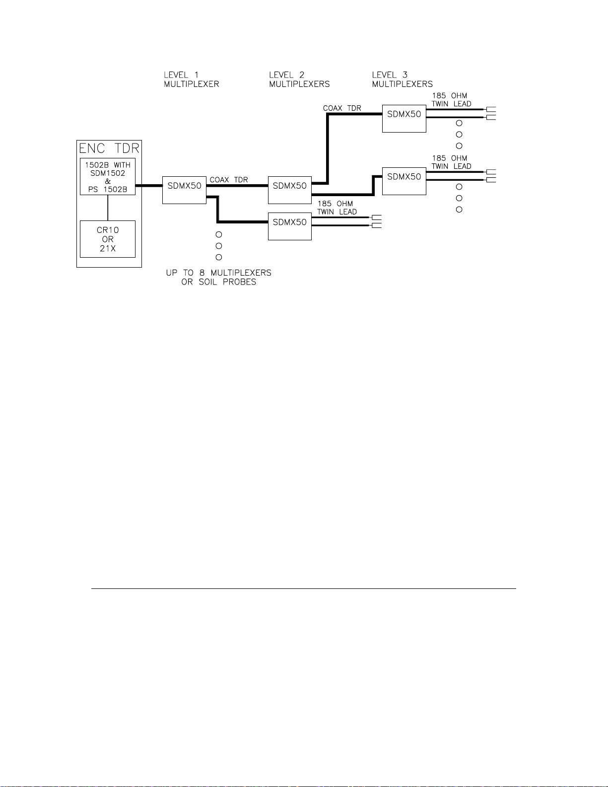
FIGURE 2-1. TDR System Components
2. SYSTEM COMPONENTS
1502B - Tektronix 1502B TDR Cable Tester.
SDM1502 - Communication Interface; this module plugs into the 1502B or 1502C and provides
a Synchronous Device for Measurement (SDM) interface to a CR10 or 21X datalogger.
PS1502B Power Control Module plugs into the battery receptacle of the 1502B; provides for
connection to an external 12 VDC source and allows the datalogger to control power to
the 1502B.
SDMX50 - 50 Ohm Coax Multiplexer - 8 to 1, BNC connectors, enclosure included. This
multiplexer is used to connect additional multiplexers or probes. Balanced probes
attached to this multiplexer require a balun for each probe.
PB30B (-RG8 or -RG58) - 30 cm soil probes; two rods, balanced design, with balun molded in
cable. A BNC connector on the coax cable attaches directly to SDMX50. The -RG8
version uses a low loss coax cable. The -RG58 version uses RG58 coax cable.
COAX TDR - 50 ohm coax cable with BNC connectors for connecting multiplexer.
6549 - 5 conductor cable used for SDM connection between datalogger and multiplexers.
21X or CR10 - The datalogger communicates with the 1502B and multiplexers with the SDM
interface using control ports 1-3 (and single ended channel 1 on the 21X). An additional
control port is used to switch power to the 1502B.
ENC TDR - Enclosure to hold 1502B and datalogger. The ENC TDR includes a transient
suppressor and cabling for connecting the power supply and datalogger. The 1502B
mount allows it to swing out to view screen.
Datalogger Software - Special PROMS for the CR10 or 21X datalogger include Instruction 100
for controlling the 1502B and multiplexers.
6590 - Transient suppressor attaches to cable from 1502B and is required if ENC TDR is
purchased.
3. INSTALLATION
The 1502B and datalogger are housed in the
ENC TDR. In most instances power is supplied
from an external 12 volt deep cycle battery
charged by a MSX18R solar panel. Each
SDMX50 multiplexer has its own enclosure.
not
Coax cable connects the 1502B and the
SDMX50 and SDMX50 to other SDMX50s. In
addition to the coax cable that carries the TDR
signal, the multiplexers must be connected to
the datalogger by a 5 conductor cable which
provides power to the multiplexers and allows
the datalogger to control the multiplexer
switching.
2
Page 6

3.1 ASSIGNING ADDRESSES
The SDM1502 and SDMX50 are Synchronous
Devices for Measurement (SDM); the
datalogger communicates with these devices
via control ports 1, 2, and 3 (and analog
channel 1H on the 21X). Addresses set in the
devices allow the datalogger to communicate
with the correct device.
There are sixteen possible addresses; a
maximum of four are used in a TDR system.
The address assigned the SDM1502
determines the addresses that need to be
assigned to the multiplexers: The multiplexer
with its input connected to the cable from the
1502B is level 1, level 2 multiplexers are those
connected to the level 1 multiplexer, level 3
multiplexers are those connected to a level 2
multiplexer. No more than 3 levels of
multiplexers are allowed. The level 1 address is
1 greater than that of the SDM1502. All level 2
multiplexers have the address set to that of the
SDM1502 plus 2 and all level 3 multiplexers
have the address set to that of the SDM1502
plus 3. The addresses are in base 4 (Table 3-
1); for example, if the SDM1502 address is 22,
the addresses for level one, level two, and level
three multiplexers are 23, 30 and 31,
respectively.
The address for the SDM1502 is set with
switches; the switches can be reached through
an access hole in the case (Figure 3-1). Table
3-1 lists the address settings.
TDR SOIL MOISTURE MEASUREMENTS
FIGURE 3-1. Address Switch on SDM1502
The address for the SDMX50 is set with
jumpers. There are two jumpers on each
multiplexer. The jumpers are labeled MSD for
Most Significant Digit and LSD for Least
Significant Digit. Each jumper has four pairs of
pins. Depending which pair of pins is
connected with the jumper, the digit can have
the value of 0, 1, 2, or 3 (Figure 3-2). Table 3-1
lists the address settings.
FIGURE 3-2. Location of Address Jumpers on SDMX50
3
Page 7

TDR SOIL MOISTURE MEASUREMENTS
FIGURE 3-3. Mounting 1502B in ENC TDR
TABLE 3-1. SDM Addresses
ADDRESS SDM1502 SDMX50
Base 4 Switches Jumper Settings
1234 MSD LSD
00 0000 0 0
01 1000 0 1
02 0100 0 2
03 1100 0 3
10 0010 1 0
11 1010 1 1
12 0110 1 2
13 1110 1 3
20 0001 2 0
21 1001 2 1
22 0101 2 2
23 1101 2 3
30 0011 3 0
31 1011 3 1
32 0111 3 2
33 1111 3 3
3.2 INSTALLING 1502B IN ENC TDR
The 1502B is mounted in the ENC TDR
enclosure by removing the handle (the required
Allen wrench is included with the ENC TDR)
and installing as shown in Figure 3-3.
3.3 DATALOGGER WIRING
3.3.1 SDM Wiring
Figure 3-4 shows the wiring of the SDM
communication cables from the SDM1502 and
SDMX50 to the datalogger. With the 21X, the
C1 connection from the SDM1502 must be
wired into analog input 1H with a 10 kilohm
resistor to C1. (This resistor is the short black
cable that is fastened to the SDM1502 handle
with a wire tie for shipping.) The resistor is not
used with the CR10.
The SDM1502 terminals are labeled above
the connector. The description for the
multiplexer terminals is on a label inside the
enclosure lid.
4
Page 8

TDR SOIL MOISTURE MEASUREMENTS
3.3.2 PS1502B
The PS1502B has three connections to the
datalogger: +12, Ground, and a control input
which allows the datalogger to switch the power
to the 1502B. In the example program
(Section 5), the control input is connected to
control port 4.
3.4. SOIL PROBES
The PB30 consists of two 30 centimeter
stainless rods and a twinlead cable. The
probes are shipped without the cable attached.
The rods are attached with the supplied screw
and star washer (Figure 3-5).
The two rods of the probe are pressed into the
soil with the rods parallel. The cable leads allow
the common 5 centimeter rod spacing.
The cable on the probe has a BNC connector
that connects directly to the SDMX50.
FIGURE 3-4. SDM Wiring
FIGURE 3-5. PB30 Assembly
5
Page 9

TDR SOIL MOISTURE MEASUREMENTS
3.5 GROUNDING
The TDR system should be installed with a
single ground point. A good earth ground
should be established close to the
datalogger/1502B.
A copper clad grounding rod comes with the
CM10 tripod or may be obtained along with
necessary clamps and wire from an electrical
supply house.
The ENC TDR has ground connections for the
datalogger, 1502B and 6590 Transient
Suppressor which are connected to a grounding
lug in the lower left corner of the enclosure. A
short run of heavy gage (10 AWG or lower) wire
should be connected from the lug to the earth
ground.
The ground lug on the multiplexer enclosures
should only be used if the multiplexer is close
enough to conveniently use the same ground
point as the datalogger.
3.6 BATTERY CONNECTIONS
Two terminal strip adapters for the battery posts
are provided with the ENC TDR (Figure 3-6).
These terminal strips will mount to the wing nut
battery posts on most deep cycle lead acid
batteries.
Options in instruction allow:
finding a soil moisture probe automatically
or specifying the "distance" to the probe
calculating water content or storing raw
waveform data
the starting point and time resolution of the
raw waveform.
Instruction 100 may also be used to step
through the multiplexers while manually
controlling the 1502B to examine the
waveforms, and to check the signature of the
PROM in the SDM1502
INSTRUCTION 100 PARAMETERS
PAR. DATA
NO. TYPE DESCRIPTION
01: 2 SDM1502 address
02: 2 Output option
0 Water content
1 Raw data
98 Manual step through
99 SDM1502 signature
03: FP Probe length, meters
04: FP Cable length, meters;
enter 0 for auto search
05: 4 Multiplexer channel/Reps
ABCD
A Chan. of 1st Mux, 0 if none
B Chan. of 2nd Mux, 0 if none
C Chan. of 3rd Mux, 0 if none
D No. of Probes to scan
06: 4 Input location
07: FP Multiplier
08: FP Offset
FIGURE 3-6. Terminal Strip Adapters for
Connections to Battery
4. PROGRAMMING INSTRUCTION 100
Instruction 100 is used to make TDR
measurements. A separate Instruction 100 is
entered for each multiplexer that has probes to
be measured or to measure separate groups of
probes on a single multiplexer.
6
Input Locations altered:
Water content - 1 per probe scanned
Raw data - 256 per probe scanned
Intermediate Locations required:
531 the first time Instruction 100 is used
16 intermediate locations for each
Instruction 100 thereafter.
Parameter 1, address: the address set into
the SDM1502 (Section 3.1).
Parameter 2 output option:
"Water Content", Code 0: the instruction
determines the end points of the probe using
the algorithm described by Baker and Allmaras,
Page 10

TDR SOIL MOISTURE MEASUREMENTS
1990, and calculates 1/Vp; the multiplier and
offset (parameters 7 and 8) may be used to
obtain the result directly in volumetric water
content (Section 5).
"Raw data", Code 1: 256 values are output for
each probe measured; the 251 values from the
waveform followed by the distance to the cursor
in meters, the distance between waveform
points, the gain, the offset, and the sample
number.
"Manual Step Through", Code 98: When the
program is compiled and run, the 1502B will be
left under manual control and the datalogger will
switch to the first channel and pause. To switch
to the next channel, set flag 8 (*6 Mode or with
TERM); the datalogger will switch to the next
channel and set flag 8 low. Repeatedly setting
flag 8 allows the user to step through all
programmed channels.
"Signature", Code 99: The signature of the
PROM in the SDM1502 is calculated and stored
in the location specified in parameter 6.
Parameter 3, Probe Length: The length of the
soil probe in meters. This length is used to
calculate the water content result (apparent
length divided by actual length, or 1/Vp), and to
determine the time/length resolution of the
waveform captured for the water content
calculation or raw output.
The probe length parameter is used to set the
resolution of the raw waveform for applications
where there is no actual "probe length". Table
4-1 lists the distance per division used at
different probe lengths.
TABLE 4-1. Waveform Resolution
Determined by Probe Length
Probe Length Distance/Division
0 to 0.02 0.025
0.03 to 0.06 0.05
0.07 to 0.13 0.1
0.14 to 0.2 0.25
0.3 to 0.4 0.5
0.5 to 0.9 1.0
1.0 to 2.0 2.5
2.1 to 4.3 5.0
4.4 to 9.2 10.0
9.3 to 9.9 25.0
> 10.0 50.0
Parameter 4 Cable length: The "length" in
meters to the probe or 1502B cursor. Enter "0"
and the datalogger will automatically search for
the soil probe.
This "length" is not the actual length as
measured with a meter stick; it is the distance
the 1502B measures using a propagating
velocity of 0.99 the speed of light (Vp = 0.99).
When capturing the waveform for raw output or
calculating water content, the cursor (start of
probe) is placed 1 division into the 1502B
display (10 divisions total).
If an automatic search for the soil probe fails,
and it is desired to enter the length to the cable,
it can be determined by manually stepping
through the multiplexer and finding the probe
with the 1502B display.
Parameter 5, Multiplexer channel/Reps:
Determines the multiplexer, first measurement
channel, and number of probes to measure.
The entry required is: channel number on level
1 multiplexer, channel on level 2 multiplexer,
channel on level 3 multiplexer, and number of
probes to measure. For example, 1008 would
indicate that there is 1 multiplexer; start on
channel 1 and step through 8 probes. The entry
2318 tells the datalogger to set the level one
multiplexer to channel 2, the level two
multiplexers to channel 3, and measure 8
probes that are connected to channels 1-8 on
the level 3 multiplexer.
Parameter 6, Input location: The Input
location in which to start storing data. When
outputting water content, one location is used
for each probe measured. When outputting raw
data, 256 locations are required for each
repetition.
5. CALIBRATION FOR WATER CONTENT
When the water content output option is
selected, the datalogger calculates the ratio of
the apparent length of the probe (the 1502B
results are in terms of length) to the actual
length as entered in parameter 3. The
datalogger corrects the length to what it would
be if the propagation velocity was the speed of
light. Thus, the ratio of lengths is the same as
the ratio of the speed of light divided by the
velocity of the signal down the probe.
7
Page 11

TDR SOIL MOISTURE MEASUREMENTS
The propagating velocity, Vp is defined as the
ratio of the actual velocity divided by the speed
of light. The result from the datalogger (with a
multiplier of 1 and an offset of 0) is 1/V
.
p
A multiplier of 0.1138 and an offset of -0.1758
gives volumetric water fraction using the
calibration of Ledieu et. al. 1986 (normalized to
accommodate probes of varying length):
= 0.1138/Vp - 0.1758
W
v
Topp et. al. 1980, used a third order equation to
equate volumetric water content, W
apparent dielectric constant Ka. Ka=(1/V
v
, to
)2;
p
with this substitution, the equation is
= -0.053+0.0292(1/Vp)2-0.00055(1/Vp)
W
v
+0.0000043(1/Vp)
6
4
Example 2 uses Topp's calibration.
0.7
0.6
0.5
0.4
0.3
0.2
0.1
VOLUMETRIC WATER CONTENT
0
1 3 5 7
1/Vp
LEDIEU TOPP
seconds each on subsequent
measurements). The program must be
written so that analog measurements,
output intervals other time based decisions
take this into account.
Switching power to the 1502B is valuable not
only for the conservation of batteries; it also
allows the 1502B to be reset if it should "bomb".
If the 1502B or 1502C does not respond
correctly to the datalogger's commands, -99999
will be loaded into the input locations that would
normally contain the results of the
measurements.
6.1 EXAMPLE 1, MEASURE AND RECORD EVERY HOUR
The following program is executed once an
hour. A single multiplexer with eight probes is
measured. The 1502B is switched on, the
measurements made with output in water
content using Ledieu's calibration, the 1502B is
switched off, and the time and 8 water content
measurements are output to Final Storage.
* 1 Table 1 Programs
01: 3600 Sec. Execution Interval
01: P86 Do
01: 44 Set high Port 4
02: P22 Excitation with Delay
01: 1 EX Chan
02: 0 Delay w/EX (units=.01sec)
03: 500 Delay after EX (units=.01sec)
04: 0 mV Excitation
FIGURE 5-1. Comparison of Calibrations
from Topp and Ledieu
6. PROGRAMMING EXAMPLES
There are several things to keep in mind when
writing a datalogger program to make TDR
measurements:
1. Set the control port high that controls the
PS 1502B 5 seconds prior to executing
Instruction 100. Switch it off after all
measurements are made.
2. TDR measurements require considerably
more time than other measurements
(approximately 1 minute each on the first
pass when finding the probe and 15 to 20
8
03: P100 SDM-1502
01: 11 Address
02: 0 Moisture
03: .3 Probe length (meters)
04: 0 Cable length (meters)
05: 1008 MMMP--Mux channels & Probes
06: 1 Loc [:WATER #1 ]
07: 0.1138 Mult
08: -0.1758 Offset
04: P86 Do
01: 54 Set low Port 4
05: P86 Do
01: 10 Set high Flag 0 (output)
06: P77 Real Time
01: 110 Day,Hour-Minute
Page 12

TDR SOIL MOISTURE MEASUREMENTS
07: P70 Sample
01: 8 Reps
02: 1 Loc WATER #1
08: P End Table 1
* A Mode 10 Memory Allocation
01: 28 Input Locations
02: 540 Intermediate Locations
6.2 EXAMPLE 2, HOURLY AVERAGE USING TOPP'S CALIBRATION
In this example measurements are made every
15 minutes and the average is output each
hour.
Note that Instruction 92, that sets the output
flag, is placed ahead of Instruction 100.
Instruction 92 has to be executed within the
specified minute in order to execute the
command. If it were after Instruction 100, the
actual time of execution would be a minute or
more after the even 15 minute interval on which
the table is executed (i.e., Flag 0 would never
be set).
05: P100 SDM-1502
01: 11 Address
02: 0 Moisture
03: .3 Probe length (meters)
04: 0 Cable length (meters)
05: 1008 MMMP--Mux channels & Probes
06: 1 Loc [:Wv #1 ]
07: 1 Mult
08: 0 Offset
06: P86 Do
01: 54 Set low Port 4
07: P87 Beginning of Loop
01: 0 Delay
02: 8 Loop Count
08: P36 Z=X*Y
01: 1-- X Loc Wv #1
02: 1-- Y Loc Wv #1
03: 1-- Z Loc [:Wv #1 ]
09: P37 Z=X*F
01: 1-- X Loc Wv #1
02: .1 F
03: 1-- Z Loc [:Wv #1 ]
This program uses Topp's calibration. A
multiplier of 1 and an offset of 0 results in output
of 1/Vp from Instruction 100. This result is
squared and multiplied by 0.1 before being
operated on by the polynomial. The factor of
0.1 allows the coefficients for the polynomial to
be scaled so all significant digits can be entered
in the polynomial Instruction 55.
* 1 Table 1 Programs
01: 900 Sec. Execution Interval
Every 15 minutes
01: P92 If time is
01: 0 minutes into a
02: 60 minute interval
03: 10 Set high Flag 0 (output)
02: P77 Real Time
01: 110 Day,Hour-Minute
03: P86 Do
01: 44 Set high Port 4
04: P22 Excitation with Delay
01: 1 EX Chan
02: 0 Delay w/EX (units=.01sec)
03: 500 Delay after EX (units=.01sec)
04: 0 mV Excitation
10: P95 End
11: P55 Polynomial
01: 8 Reps
02: 1 X Loc Wv #1
03: 1 F(X) Loc [:Wv #1 ]
04: -0.053 C0
05: .292 C1
06: -0.055 C2
07: 0.0043 C3
08: 0 C4
09: 0 C5
12: P71 Average
01: 8 Reps
02: 1 Loc Wv #1
13: P End Table 1
* A Mode 10 Memory Allocation
01: 28 Input Locations
02: 550 Intermediate Locations
9
Page 13

TDR SOIL MOISTURE MEASUREMENTS
6.3 EXAMPLE 3, TDR MEASUREMENTS IN TABLE 2 WITH ANALOG MEASUREMENTS IN TABLE 1
This example is for 4 multiplexers. The level 1
multiplexer has a multiplexer connected to each
of channels 1, 2, and 3 and probes connected
to channels 4 through 8. The second level
multiplexers each have 8 probes. The
measurements are made every 30 minutes and
the averages are output every 4 hours.
Placing the TDR measurements in Table 2
allows analog measurements to be made in
Table 1. The analog measurements will
continue to be made during TDR
measurements because Table 1 can interrupt
Table 2.
The interruption cannot take place if the output
flag is set in Table 2. Note that Instruction 92 is
used to set flag 1 every 4 hours prior to making
the TDR measurements. After making the
measurements, flag 1 is checked to see if it is
time for output.
* 1 Table 1 Programs
01: 10 Sec. Execution Interval
Table 1 contains the program for making analog
measurements; for example, a meteorological
station or a number of soil temperatures. The
measurements in Table 1 will be made at their
scheduled interval even while the TDR
measurements are made in Table 2 because
Table 1 can interrupt Table 2.
01: P End Table 1
* 2 Table 2 Programs
01: 60 Sec. Execution Interval
01: P92 If time is
01: 0 minutes into a
02: 30 minute interval
03: 30 Then Do
02: P92 If time is
01: 0 minutes into a
02: 240 minute interval
03: 11 Set high Flag 1
03: P86 Do
01: 44 Set high Port 4
04: P100 SDM-1502
01: 22 Address
02: 0 Moisture
03: .3 Probe length (meters)
04: 0 Cable length (meters)
05: 4005 MMMP--Mux channels & Probes
06: 21 Loc [:MUX 1 #1 ]
07: 0.1138 Mult
08: -.1758 Offset
05: P100 SDM-1502
01: 22 Address
02: 0 Moisture
03: .3 Probe length (meters)
04: 0 Cable length (meters)
05: 1108 MMMP--Mux channels & Probes
06: 26 Loc [:MUX 2-1#1]
07: 0.1138 Mult
08: 0.1758 Offset
06: P100 SDM-1502
01: 22 Address
02: 0 Moisture
03: .3 Probe length (meters)
04: 0 Cable length (meters)
05: 2108 MMMP--Mux channels & Probes
06: 34 Loc [:MUX 2-2#1]
07: 0.1138 Mult
08: 0.1758 Offset
07: P100 SDM-1502
01: 22 Address
02: 0 Moisture
03: .3 Probe length (meters)
04: 0 Cable length (meters)
05: 3108 MMMP--Mux channels & Probes
06: 42 Loc [:MUX 2-3#1]
07: 0.1138 Mult
08: 0.1758 Offset
08: P86 Do
01: 54 Set low Port 4
09: P91 If Flag/Port
01: 11 Do if Flag 1 is high
02: 10 Set high Flag 0 (output)
10: P86 Do
01: 21 Set low Flag 1
11: P77 Real Time
01: 110 Day,Hour-Minute
12: P71 Average
01: 29 Reps
02: 21 Loc MUX 1 #1
10
Page 14

13: P95 End
14: P End Table 2
* A Mode 10 Memory Allocation
01: 50 Input Locations
02: 700 Intermediate Locations
LITERATURE CITED
Baker, J.M. and R.R. Allmaras. 1990.
System for Automating and Multiplexing
Soil Moisture Measurement by TimeDomain Reflectometry.
Society of America Journal
Ledieu, J., P. DeRidder, P. DeClerck and S.
Dautrebande. 1986. A Method of
Measuring Soil Moisture by TimeDomain Reflectometry.
Hydrology
88: 319-328.
Soil Science
54: 1-6.
Journal of
TDR SOIL MOISTURE MEASUREMENTS
Topp, G.C., J.L. Davis, and A.P. Annan.
1980. Electromagnetic Determination
of Soil Water Content: Measurements
in Coaxial Transmission Lines.
Resources Research
16.3: 574-582.
Water
11
 Loading...