

Page 1
TB4, TB4MM,
CS700, CS700H
Tipping Bucket Rain Gages
Revision
Copyright ©
Campbell Scientific, Inc.
: 8/19
1995 – 2019
Page 2

Limited Warranty
“Products manufactured by CSI are warranted by CSI to be free from defects in
materials and workmanship under normal use and service for twelve months
from the date of shipment unless otherwise specified in the corresponding
product manual. (Product manuals are available for review online at
www.campbellsci.com.) Products not manufactured by CSI, but that are resold
by CSI, are warranted only to the limits extended by the original manufacturer.
Batteries, fine-wire thermocouples, desiccant, and other consumables have no
warranty. CSI’s obligation under this warranty is limited to repairing or
replacing (at CSI’s option) defective Products, which shall be the sole and
exclusive remedy under this warranty. The Customer assumes all costs of
removing, reinstalling, and shipping defective Products to CSI. CSI will return
such Products by surface carrier prepaid within the continental United States of
America. To all other locations, CSI will return such Products best way CIP
(port of entry) per Incoterms ® 2010. This warranty shall not apply to any
Products which have been subjected to modification, misuse, neglect, improper
service, accidents of nature, or shipping damage. This warranty is in lieu of all
other warranties, expressed or implied. The warranty for installation services
performed by CSI such as programming to customer specifications, electrical
connections to Products manufactured by CSI, and Product specific training, is
part of CSI's product warranty. CSI EXPRESSLY DISCLAIMS AND
EXCLUDES ANY IMPLIED WARRANTIES OF MERCHANTABILITY
OR FITNESS FOR A PARTICULAR PURPOSE. CSI hereby disclaims,
to the fullest extent allowed by applicable law, any and all warranties and
conditions with respect to the Products, whether express, implied or
statutory, other than those expressly provided herein.”
Page 3

Assistance
Products may not be returned without prior authorization. The following
contact information is for US and international customers residing in countries
served by Campbell Scientific, Inc. directly. Affiliate companies handle repairs
for customers within their territories. Please visit www.campbellsci.com to
determine which Campbell Scientific company serves your country.
To obtain a Returned Materials Authorization (RMA) number, contact
CAMPBELL SCIENTIFIC, INC., phone (435) 227-9000. Please write the
issued RMA number clearly on the outside of the shipping container. Campbell
Scientific’s shipping address is:
CAMPBELL SCIENTIFIC, INC.
RMA#_____
815 West 1800 North
Logan, Utah 84321-1784
For all returns, the customer must fill out a “Statement of Product Cleanliness
and Decontamination” form and comply with the requirements specified in it.
The form is available from our website at www.campbellsci.com/repair. A
completed form must be either emailed to repair@campbellsci.com or faxed to
(435) 227-9106. Campbell Scientific is unable to process any returns until we
receive this form. If the form is not received within three days of product
receipt or is incomplete, the product will be returned to the customer at the
customer’s expense. Campbell Scientific reserves the right to refuse service on
products that were exposed to contaminants that may cause health or safety
concerns for our employees.
Page 4

Safety
DANGER — MANY HAZARDS ARE ASSOCIATED WITH INSTALLING, USING, MAINTAINING, AND WORKING ON OR AROUND
TRIPODS, TOWERS, AND ANY ATTACHMENTS TO TRIPODS AND TOWERS SUCH AS SENSORS, CROSSARMS, ENCLOSURES,
ANTENNAS, ETC. FAILURE TO PROPERLY AND COMPLETELY ASSEMBLE, INSTALL, OPERATE, USE, AND MAINTAIN TRIPODS,
TOWERS, AND ATTACHMENTS, AND FAILURE TO HEED WARNINGS, INCREASES THE RISK OF DEATH, ACCIDENT, SERIOUS
INJURY, PROPERTY DAMAGE, AND PRODUCT FAILURE. TAKE ALL REASONABLE PRECAUTIONS TO AVOID THESE HAZARDS.
CHECK WITH YOUR ORGANIZATION'S SAFETY COORDINATOR (OR POLICY) FOR PROCEDURES AND REQUIRED PROTECTIVE
EQUIPMENT PRIOR TO PERFORMING ANY WORK.
Use tripods, towers, and attachments to tripods and towers only for purposes for which they are designed. Do not exceed design limits.
Be familiar and comply with all instructions provided in product manuals. Manuals are available at www.campbellsci.com or by
telephoning (435) 227-9000 (USA). You are responsible for conformance with governing codes and regulations, including safety
regulations, and the integrity and location of structures or land to which towers, tripods, and any attachments are attached. Installation
sites should be evaluated and approved by a qualified engineer. If questions or concerns arise regarding installation, use, or
maintenance of tripods, towers, attachments, or electrical connections, consult with a licensed and qualified engineer or electrician.
General
• Prior to performing site or installation work, obtain required approvals and permits. Comply
with all governing structure-height regulations, such as those of the FAA in the USA.
• Use only qualified personnel for installation, use, and maintenance of tripods and towers, and
any attachments to tripods and towers. The use of licensed and qualified contractors is highly
recommended.
• Read all applicable instructions carefully and understand procedures thoroughly before
beginning work.
• Wear a hardhat and eye protection, and take other appropriate safety precautions while
working on or around tripods and towers.
• Do not climb tripods or towers at any time, and prohibit climbing by other persons. Take
reasonable precautions to secure tripod and tower sites from trespassers.
• Use only manufacturer recommended parts, materials, and tools.
Utility and Electrical
• You can be killed or sustain serious bodily injury if the tripod, tower, or attachments you are
installing, constructing, using, or maintaining, or a tool, stake, or anchor, come in contact with
overhead or underground utility lines.
• Maintain a distance of at least one-and-one-half times structure height, 20 feet, or the distance
required by applicable law, whichever is greater, between overhead utility lines and the
structure (tripod, tower, attachments, or tools).
• Prior to performing site or installation work, inform all utility companies and have all
underground utilities marked.
• Comply with all electrical codes. Electrical equipment and related grounding devices should be
installed by a licensed and qualified electrician.
Elevated Work and Weather
• Exercise extreme caution when performing elevated work.
• Use appropriate equipment and safety practices.
• During installation and maintenance, keep tower and tripod sites clear of un-trained or non-
essential personnel. Take precautions to prevent elevated tools and objects from dropping.
• Do not perform any work in inclement weather, including wind, rain, snow, lightning, etc.
Maintenance
• Periodically (at least yearly) check for wear and damage, including corrosion, stress cracks,
frayed cables, loose cable clamps, cable tightness, etc. and take necessary corrective actions.
• Periodically (at least yearly) check electrical ground connections.
WHILE EVERY ATTEMPT IS MADE TO EMBODY THE HIGHEST DEGREE OF SAFETY IN ALL CAMPBELL SCIENTIFIC PRODUCTS,
THE CUSTOMER ASSUMES ALL RISK FROM ANY INJURY RESULTING FROM IMPROPER INSTALLATION, USE, OR
MAINTENANCE OF TRIPODS, TOWERS, OR ATTACHMENTS TO TRIPODS AND TOWERS SUCH AS SENSORS, CROSSARMS,
ENCLOSURES, ANTENNAS, ETC.
Page 5

Table of Contents
PDF viewers: These page numbers refer to the printed version of this document. Use the
PDF reader bookmarks tab for links to specific sections.
1. Introduction................................................................ 1
2. Precautions ................................................................ 1
3. Initial Inspection ........................................................ 2
3.1 Ships With ............................................................................................2
4. QuickStart .................................................................. 2
5. Overview .................................................................... 4
5.1 Wind Screen .........................................................................................6
6. Specifications ............................................................ 6
6.1 Heated Rain Gage ................................................................................7
7. Installation ................................................................. 7
7.1 Wiring ..................................................................................................7
7.1.1 TB4, TB4M, or CS700 Connections .............................................7
7.1.2 CS700H Heated Rain Gage Connections ......................................7
7.2 Data Logger Programming ...................................................................9
7.2.1 PulseCount Instruction ................................................................ 10
7.2.2 SDI12Recorder Instruction ......................................................... 10
7.3 Siting .................................................................................................. 10
7.4 Mounting ............................................................................................ 10
7.4.1 Mounting to the CM240 and Leveling ........................................ 12
7.5 CS700H Power Supply Installation .................................................... 13
8. Operation ................................................................. 13
8.1 Sensor Schematic ............................................................................... 13
8.2 Long Cable Lengths ........................................................................... 14
8.3 CS700H Heated Rain Gage Operation ............................................... 14
8.3.1 SDI-12 Measurements ................................................................. 14
9. Troubleshooting and Maintenance ......................... 15
9.1 Troubleshooting ................................................................................. 15
9.2 Maintenance ....................................................................................... 16
9.2.1 Dismantling for Cleaning ............................................................ 16
9.2.2 Reassembling the Rain Bucket .................................................... 18
9.3 Calibration Check............................................................................... 19
i
Page 6

Table of Contents
Appendices
A. Importing Short Cut Code Into CRBasic Editor ... A-1
B. Example Programs ................................................ B-1
B.1 TB4 or CS700 Example Programs ................................................... B-1
B.1.1 CR6 Program for the TB4 or CS700 ......................................... B-1
B.1.2 CR1000X Programs for the TB4 or CS700 .............................. B-2
B.2 CS700H Example Programs ............................................................. B-4
B.2.1 CR6 Program for the CS700H .................................................. B-4
B.2.2 CR1000X Programs for CS700H .............................................. B-5
C. CS700H Operation Details ..................................... C-1
C.1 High Power Operation ...................................................................... C-3
C.2 External Control ............................................................................... C-3
C.3 Status LED ....................................................................................... C-4
C.4 Snow Sensor ..................................................................................... C-4
C.5 Operating Modes .............................................................................. C-5
C.6 SDI-12 Sensor Support .................................................................... C-6
C.6.1 Introduction ............................................................................... C-6
C.6.2 SDI-12 Command Basics .......................................................... C-6
C.6.2.1 Acknowledge Active Command (a!) .............................. C-8
C.6.2.2 Send Identification Command (aI!) ................................ C-8
C.6.2.3 Start Verification Command (aV!) ................................. C-8
C.6.2.4 Address Query Command (?!) ........................................ C-8
C.6.2.5 Change Address Command (aAb!) ................................. C-8
C.6.2.6 Start Measurement Commands (aM!) ............................ C-9
C.6.2.7 Start Concurrent Measurement Commands (aC!) .......... C-9
C.6.28 Start Measurement Commands with Cyclic
Redundancy Check (aMC! and aCC!) ...................... C-11
C.6.2.9 Stopping a Measurement Command ............................. C-11
C.6.2.10 Send Data Command (aD0! … aD9!) .......................... C-11
C.6.2.11 Continuous Measurement Command (aR0! … aR9!) .. C-12
C.6.2.12 Extended Commands .................................................... C-12
C.6.3 SDI-12 Transparent Mode....................................................... C-12
C.6.3.1 Changing an SDI-12 Address ....................................... C-13
C.6.4 References ............................................................................... C-13
D. Phoenix Contact Power Supply Specifications ... D-1
Figures
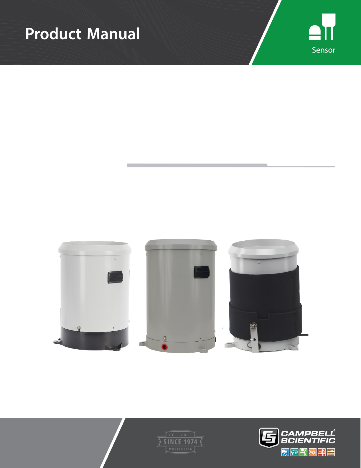
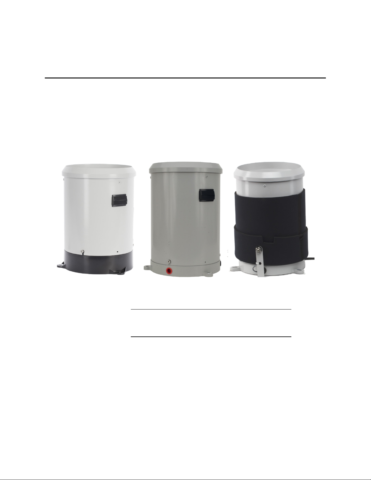
1-1. TB4 or TB4MM (left), CS700 (center), and CS700H (right)
Tipping Bucket Rain Gages ..............................................................1
5-1. CS700 Bucket Mechanism (housing not shown) .................................5
5-2. Phoenix Contact Power Supply ............................................................5
7-1. CS700H with Cables ............................................................................8
7-2. Phoenix Contact Power Supply ............................................................9
7-3. Typical Rain Gage Installation ........................................................... 11
7-4. CM300 Short Leg Pedestal Option (left) and J-Bolt Pedestal
Option ............................................................................................. 12
7-5. Transparent View of the TB4 (CS700 looks similar) ......................... 12
7-6. CM240 Mounting Bracket ................................................................. 13
ii
Page 7

Table of Contents
Tables
8-1. TB4, TB4M, and CS700 Schematic ................................................... 13
8-2. CS700H Heater Operation ................................................................. 14
9-1. Main Components of the CS700 ........................................................ 16
9-2. TB4 Base ............................................................................................ 17
9-3. Dismantling the Filter/Siphon Assembly ........................................... 17
9-4. Filter/Siphon Assembly ...................................................................... 18
9-5. Reassembling the CS700 .................................................................... 19
C-1. Locations of the CS700H Heater Components ................................ C-1
C-2. Diagram Depicting Overall Operation ............................................. C-2
C-3. Diagram showing how the “Snow Run-On” timer controls the
heater. ........................................................................................... C-3
7-1. TB4, TB4MM, or CS700 Wire Color, Wire Function, and Data
Logger Connection ...........................................................................7
7-2. CS700H Sensor Cable Wire Color, Wire Function, and Data
Logger Connection ...........................................................................8
7-3. CS700H Power Cable Wire Color, Wire Function, and Power
Supply Connection ............................................................................8
C-1. CS700H Default Values ................................................................... C-1
C-2. Status LEDs ...................................................................................... C-4
C-3. Snow Sensor Power Options ............................................................ C-5
C-4. Operating Modes .............................................................................. C-5
C-5. Campbell Scientific Sensor SDI-12 Command and Response Set ... C-7
C-6. Example aM! Sequence .................................................................... C-9
C-7. Example aC! Sequence .................................................................. C-10
CRBasic Examples
B-1. CR6 Program Measuring the TB4 or CS700 .................................... B-1
B-2. CR1000X Program Using a Pulse Terminal to Measure the TB4
or CS700 ....................................................................................... B-2
B-3. CR1000X Program Using a Control Terminal to Measure the
TB4 or CS700 ............................................................................... B-3
B-4. CR6 Program Measuring the CS700H ............................................. B-4
B-5. CR1000X Program Measuring the CS700H .................................... B-5
B-6. CR1000X Program Measuring the CS700H and Monitoring
Heater............................................................................................ B-6
iii
Page 8
NOTE
TB4, TB4MM, CS700, and CS700H
Tipping Bucket Rain Gages
1. Introduction
The TB4, TB4MM, CS700, and CS700H are tipping bucket rain gages that
funnel rain into a mechanism that tips when filled. The TB4, CS700, and
CS700H measure in 0.01-inch increments and the TB4MM measures in
0.2-mm increments. The TB4 and TB4MM have a lightweight plastic base, and
the CS700 and CS700H have a heavy-duty, cast-aluminum base (FIGURE
1-1). The CS700H is a heated rain gage for measuring the water content of
snow.
2. Precautions
FIGURE 1-1. TB4 or TB4MM (left), CS700 (center), and CS700H
(right) Tipping Bucket Rain Gages
This manual provides information only for CRBasic data loggers.
For retired Edlog data logger support, see an older manual at
www.campbellsci.com/old-manuals.
• READ AND UNDERSTAND the Safety section at the front of this
manual.
• The rain gages are precision instruments. Please handle them with care.
• Before using the rain gage, remove the rubber band and cardboard that
secures the tipping bucket assembly during shipping.
®
• The black outer jacket of the cable is Santoprene
was chosen for its resistance to temperature extremes, moisture, and UV
rubber. This compound
1
Page 9

degradation. However, this jacket will support combustion in air. It is rated
as slow burning when tested according to U.L. 94 H.B. and will pass
FMVSS302. Local fire codes may preclude its use inside buildings.
• While assembling the CS700H, ensure that the coiled cable and the
neoprene jacket do not interfere with the tipping bucket mechanism when
placing the funnel on the base.
3. Initial Inspection
• Upon receipt of the tipping bucket rain gage, inspect the packaging and
contents for damage. File damage claims with the shipping company.
Immediately check package contents against the shipping documentation
(see Section 3.1, Ships With). Contact Campbell Scientific about any
discrepancies.
• The model number and cable length are printed on a label at the
connection end of the cable. Check this information against the shipping
documents to ensure the expected product and cable length are received.
3.1 Ships With
TB4, TB4MM, CS700, and CS700H Tipping Bucket Rain Gages
4. QuickStart
The rain gages ship with:
(1) Allen wrench from original manufacturer
CS700H-AC version also ships with:
(1) Power supply and mounting hardware (Quint Power made by Phoenix
Contact)
A video that describes data logger programming using Short Cut is available at:
www.campbellsci.com/videos/cr1000x-datalogger-getting-started-programpart-3. Short Cut is an easy way to program your data logger to measure the
rain gage and assign data logger wiring terminals. Short Cut is available as a
download on www.campbellsci.com. It is included in installations of
LoggerNet, PC200W, PC400, or RTDAQ.
The following procedure also describes programming with Short Cut.
1. Open Short Cut and click Create New Program.
2. Double-click the data logger model.
2
Page 10
TB4, TB4MM, CS700, and CS700H Tipping Bucket Rain Gages
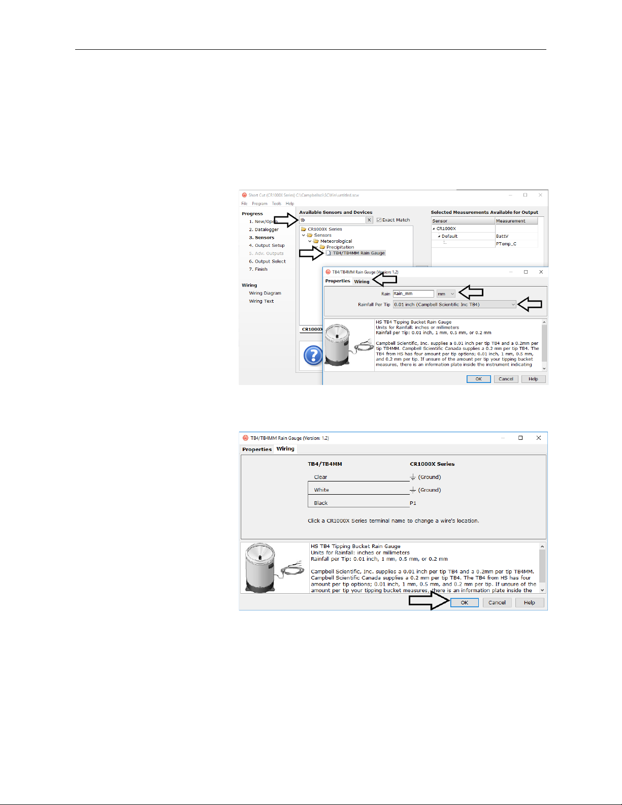
3. In the Available Sensors and Devices box, type TB4 or CS700. You can
also locate the sensor in the Sensors | Meteorological | Precipitation
folder. Double-click TB4/TB4MM or CS700 Rain Gauge. The units
defaults to millimeters, which can be changed by clicking the Rain box
and selecting one of the other options. The default rainfall per tip value of
0.01 inches should be used if the sensor is a TB4 or CS700 purchased at
Campbell Scientific (U.S. office). Select 0.2 mm if the sensor is a TB4MM
purchased at Campbell Scientific (U.S. office) or a TB4 or CS700
purchase at Campbell Scientific Canada.
4. Click on the Wiring tab to see how the sensor is to be wired to the data
logger. Click OK after wiring the sensor.
5. Repeat steps three and four for other sensors. Click Next.
3
Page 11
TB4, TB4MM, CS700, and CS700H Tipping Bucket Rain Gages
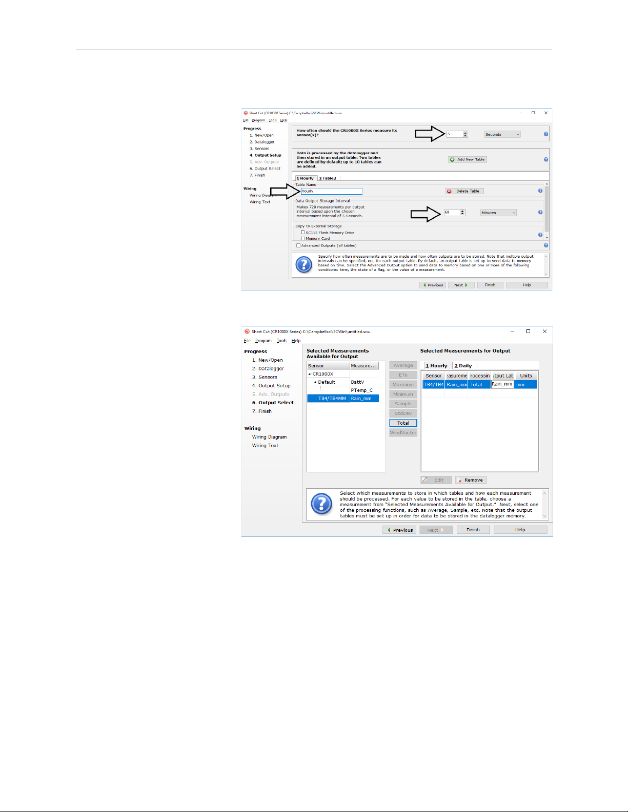
6. In Output Setup, type the scan rate, meaningful table names, and the
Data Output Storage Interval.
7. Select the output options.
5. Overview
8. Click Finish and save the program. Send the program to the data logger if
the data logger is connected to the computer.
9. If the sensor is connected to the data logger, check the output of the sensor
in LoggerNet, PC400, RTDAQ, or PC200W to make sure it is making
reasonable measurements.
The TB4, TB4MM, CS700, and CS700H tipping bucket rain gages are
manufactured by HS Hyquest Solutions Pty. Ltd. and modified for use with
Campbell Scientific data loggers. These rain gages funnel precipitation into a
bucket mechanism that tips when filled to a calibrated level (FIGURE 5-1).
The tipping mechanism activates a reed switch. The switch closure is recorded
4
Page 12
TB4, TB4MM, CS700, and CS700H Tipping Bucket Rain Gages
Bucket Mechanism
by the data logger. When the bucket tips, the water drains out the screened
fittings in the base of the gage.
The rain gages are ideal for locations where intense rainfall events may occur.
They include a siphoning mechanism that allows the rain to flow at a steady
rate regardless of rainfall intensity. The siphon reduces typical rain bucket
errors and produces accurate measurements for up to 50 cm per hour.
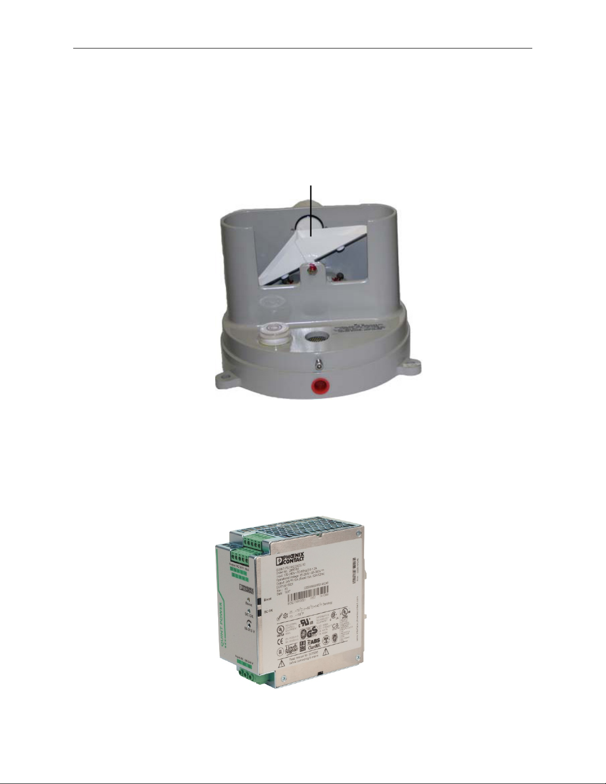
FIGURE 5-1. CS700 Bucket Mechanism (housing not shown)
The CS700H has two power configuration options (either AC or DC) for
powering the heater. With the AC option, a Phoenix Contact Power Supply is
shipped with the CS700H (FIGURE 5-2). Appendix D, Phoenix Contact Power
Supply Specifications
(p. D-1), provides more information about this power
supply.
FIGURE 5-2. Phoenix Contact Power Supply
5
Page 13

With the DC option, the CS700H is connected to a user-supplied battery. This
option is ideal for remote sites using wind or solar power to recharge the
battery. Battery capacity requirements vary according to the application and
site location.
5.1 Wind Screen
The 260-953 Alter-Type Wind Screen can be used with the rain gage to
minimize the effects of strong winds. Siting information and the installation
procedure for this wind screen is provided in our 260-953 manual.
6. Specifications
Features:
Orifice Diameter: 200 mm (7.87 in)
TB4, TB4MM, CS700, and CS700H Tipping Bucket Rain Gages
• More accurate measurement of high-intensity precipitation
• High precision
• Compatible with Campbell Scientific CRBasic data loggers:
CR200(X) series (except CS700H), CR300 series (except CS700H),
CR6 series, CR800 series, CR1000, CR1000X, CR3000, CR5000,
and CR9000(X) (except CS700H)
Measurement Range: 0 to 700 mm/hr (0 to 27.6 in/hr)
Accuracy: ±2% @ < 250 mm/hr (9.8 in/hr);
±3% @ 250 to 500 mm/hr (9.8 to 19.7 in/hr)
Resolution
TB4, CS700, CS700H: 0.254 mm (0.01 in)
TB4MM: 0.2 mm (0.008 in)
Temperature Range
TB4, TB4MM, CS700: 0 to 70 °C
CS700H: –40 to 70 °C
Humidity: 0 to 100%
Contact: Dual Reed Switch
Drain Tube: Both filters accept 12 mm inner diameter
tubing
Siphon: 0.4 mm (12 ml) capacity of rainfall; made
from brass with a non-hydroscopic outer
case. The syphon can be dismantled for
routine cleaning and servicing.
Weight with 25-ft signal cable
TB4/TB4MM: 2 kg (4.4 lb)
CS700/CS700H: 3.3 kg (7.4 lb)
Height
TB4/TB4MM: 33 cm (13 in)
CS700/CS700H: 34.2 cm (13.5 in)
6
Page 14
6.1 Heated Rain Gage
TABLE 7-1. TB4, TB4MM, or CS700 Wire Color, Wire Function,
⏚
⏚
⏚
NOTE
CAUTION
7. Installation
TB4, TB4MM, CS700, and CS700H Tipping Bucket Rain Gages
Snow Sensor and Heater
Operating Temperature Range: –20 to 5 °C
Output: SDI-12
Voltage Requirements
Main Power: 10 to 30 VDC or 12 to 28 VAC
SDI-12 Power: 9.6 to 16 VDC
Total Current Consumption
Snow sensor off, heater off: 6 mA @ 12 V, 0.072 W
Snow sensor on, heater off: 12 mA @ 12 V, 0.144 W
Snow sensor on, heater on: 5.8 A @ 12 V, 70 W
Specifications for the power supply used for the –AC option is
provided in Appendix D, Phoenix Contact Power Supply
Specifications
If programming the data logger with Short Cut, skip Section 7.1, Wiring (p. 7),
and Section 7.2, Data Logger Programming
you. See Section 4, QuickStart
(p. D-1).
(p. 9). Short Cut does this work for
(p. 2), for a Short Cut tutorial.
7.1 Wiring
7.1.1 TB4, TB4M, or CS700 Connections
and Data Logger Connection
Data Logger
Wire
Color
Black Rain Signal
White
Clear Shield
1
U and C terminals are automatically configured by the measurement instruction.
7.1.2 CS700H Heated Rain Gage Connections
The CS700H will only communicate over SDI-12 when both
its sensor cable and power cable are connected.
Wire
Function
Rain Signal
Reference
Connections Using a
Pulse Terminal
P, P_SW, or U1
(Pulse Terminal)
(Analog Ground)
(Analog Ground)
Data Logger
Connections Using a
Control Terminal
C
(Control Terminal)
5 V
(Analog Ground)
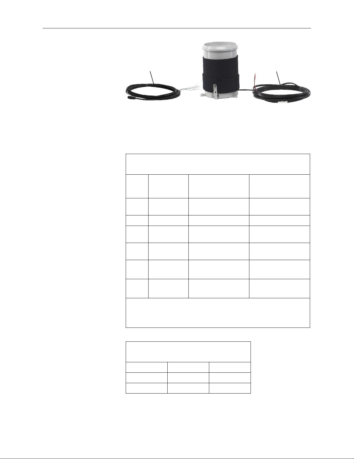
The CS700H has both a sensor cable and a power cable (FIGURE 7-1).
7
Page 15
TB4, TB4MM, CS700, and CS700H Tipping Bucket Rain Gages
TABLE 7-2. CS700H Sensor Cable Wire Color, Wire Function,
⏚
⏚
⏚
TABLE 7-3. CS700H Power Cable Wire Color,
Sensor Cable
Power Cable
FIGURE 7-1. CS700H with Cables
The sensor cable connects to the data logger (TABLE 7-2). The power cable
connects to the power supply (TABLE 7-3). FIGURE 7-2 shows the terminals
for connecting the power cable to the Phoenix Contact Power Supply.
and Data Logger Connection
Wire
Color
Wire
Function
Green SDI-12
Data Logger
Connections Using a
Pulse Terminal
Odd-numbered C or U
configured for SDI-12
1
Data Logger
Connections Using a
Control Terminal
Odd-numbered C or U1
configured for SDI-12
Red SDI-12 Power 12V 12V
Blue
Black Rain Signal
White
Clear Shield
1
U and C terminals are automatically configured by the measurement instruction.
2
When using a CR6 or CR1000X, a conflict occurs if the pulse measurement uses an
even C terminal that immediately follows the SDI-12 terminal. For example, if C1 is
used for the SDI-12 terminal, do not use C2 for the pulse terminal.
SDI-12 Power
Ground
Rain Signal
Reference
G G
P or U1
(Pulse Terminal)
(Analog Ground)
(Analog Ground)
C2
(Control Terminal)
5 V
(Analog Ground)
Wire Function, and Power Supply Connection
Wire Color Description Power Supply
Red +24 VDC +
Black Ground –
8
Page 16

TB4, TB4MM, CS700, and CS700H Tipping Bucket Rain Gages
NOTE
Power Out:
Power In:
110 VAC Adapter
Connects to CS700H
FIGURE 7-2. Phoenix Contact Power Supply
7.2 Data Logger Programming
Short Cut is the best source for up-to-date data logger programming code.
If your data acquisition requirements are simple, you can probably create and
maintain a data logger program exclusively with Short Cut. If your data
acquisition needs are more complex, the files that Short Cut creates are a great
source for programming code to start a new program or add to an existing
custom program.
Short Cut cannot edit programs after they are imported and edited
in CRBasic Editor.
A Short Cut tutorial is available in Section 4, QuickStart (p. 2). If you wish to
import Short Cut code into CRBasic Editor to create or add to a customized
program, follow the procedure in Appendix A, Importing Short Cut Code Into
CRBasic Editor
Programming basics for CRBasic data loggers are in the following sections.
Complete program examples for select CRBasic data loggers can be found in
Appendix B, Example Programs
(p. A-1).
(p. B-1). Programming basics and programming
Connects to
9
Page 17

TB4, TB4MM, CS700, and CS700H Tipping Bucket Rain Gages
CAUTION
examples for Edlog data loggers are provided at www.campbellsci.com/old-
manuals.
7.2.1 PulseCount Instruction
The tipping buckets use a reed switch for measuring precipitation. The
PulseCount() CRBasic instruction measures the reed switch.
PulseCount(Dest,Reps,PChan,PConfig,POption,Mult,Offset)
• Choose Switch Closure for the PConfig parameter. For the CR6 and
CR1000X, choose Switch Closure with pull up.
• The Multiplier parameter determines the units in which rainfall is
reported. For the TB4, CS700, and CS700H, a multiplier of 0.01
converts the output to inches and a multiplier of 0.254 converts the
output to millimeters. For the TB4MM, a multiplier of 0.2 converts
the output to millimeters and a multiplier of 0.008 converts it to
inches.
7.2.2 SDI12Recorder Instruction
When measuring a CS700H, the CRBasic program can include the
SDI12Recorder() instruction to retrieve real-time status information stored in
the CS700H microprocessor.
7.3 Siting
7.4 Mounting
SDI12Recorder ( Dest, SDIPort, SDIAddress, "SDICommand",
Multiplier, Offset, FillNAN, WaitonTimeout)
The Destination parameter must be an array of length 9. FillNAN and
WaitonTimeout are optional parameters (refer to CRBasic Help for more
information). Appendix C, CS700H Operation Details
information about the SDI-12 commands and other operational details for the
CS700H.
The CS700H will only communicate over SDI-12 when both
its sensor cable and power cable are connected (TABLE 7-2
and TABLE 7-3
Mount the rain gage in a relatively level location representative of the
surrounding area. Ensure that the orifice is horizontal, at least 1 m above the
ground, and higher than the average snow depth.
Place the rain gage away from objects that obstruct the wind. The distance
should be 2- to 4-times the height of the obstruction.
The tipping buckets have three equally-spaced feet for mounting them on a flat
surface. Each foot includes a hole that fits a 3/8-inch (M8) bolt. The three holes
form a 234 mm (9.21 in) diameter bolt circle.
).
(p. C-1), provides
10
Page 18

TB4, TB4MM, CS700, and CS700H Tipping Bucket Rain Gages
61 cm
(24 in)
20 cm
(8 in) dia.
CM240
CM310
61 cm
(24 in)
20 cm
(8 in) dia.
Campbell Scientific offers the CM240 mounting bracket for installing and
leveling the rain gages. The CM240 may be attached to a CM300-Series
mounting pole or to a user-supplied 1.5 in. IPS (1.9 in. OD) unthreaded pipe.
The pole or pipe can be placed directly into a concrete foundation (FIGURE
7-3), or attached to a concrete foundation using J-bolts or self-supporting with
legs (FIGURE 7-4). A concrete pad is recommended, but it should not be
installed over large paved or concrete surface.
142 cm (56 in)
mounting pole
FIGURE 7-3. Typical Rain Gage Installation
11
Page 19

TB4, TB4MM, CS700, and CS700H Tipping Bucket Rain Gages
Housing
Housing Screw
Base
Tipping Bucket
Bullseye Level
Funnel
Foot
61 cm
(24 in)
36 cm
(14 in)
4 cm (1.5 in)
9 cm (3.5 in)
FIGURE 7-4. CM300 Short Leg Pedestal Option (left) and J-Bolt
Pedestal Option
7.4.1 Mounting to the CM240 and Leveling
1. Remove the housing assembly from the base by loosening the three
housing screws and lifting the housing upward (FIGURE 7-5).
Assembly
FIGURE 7-5. Transparent View of the TB4 (CS700 looks similar)
12
Page 20

TB4, TB4MM, CS700, and CS700H Tipping Bucket Rain Gages
Black
White
Clear
100 Ω
White
Black
Clear
Leveling Screw
Leveling Screw
Leveling Screw
2. Remove the leveling screws from the CM240 (FIGURE 7-6).
FIGURE 7-6. CM240 Mounting Bracket
3. Place the tipping bucket on the CM240 and line up the holes in the tipping
bucket feet with the holes for the CM240 leveling screws (FIGURE 7-5
and FIGURE 7-6).
4. Use the leveling screws to loosely secure the rain gage to the CM240.
7.5 CS700H Power Supply Installation
8. Operation
8.1 Sensor Schematic
5. Place the CM240 and rain gage on the mounting pole.
6. Adjust the three leveling screws on the CM240 bracket to level the gage
(FIGURE 7-6). A bullseye level is mounted on the rain gage base to
facilitate leveling (FIGURE 7-5).
7. Remove the rubber band and cardboard securing the tipping bucket
assembly. Tip the bucket several times to ensure the tipping mechanism is
moving freely.
8. Replace the housing assembly and tighten the three housing screws to
secure the housing to the base.
A CS700H with option –AC includes a Phoenix Contact Power Supply that
must be housed in an environmental enclosure. A DIN rail mounting bracket is
shipped with the CS700H for securing this power supply to an enclosure
backplate. The DIN Rail mounts to the backplate using screws and grommets.
FIGURE 8-1. TB4, TB4M, and CS700 Schematic
13
Page 21

TB4, TB4MM, CS700, and CS700H Tipping Bucket Rain Gages
NOTE
8.2 Long Cable Lengths
Long cables have appreciable capacitance between the lines. A built up charge
could cause arcing when the switch closes, shortening switch life. A 100 ohm
resistor is connected in series at the switch to prevent arcing by limiting the
current (FIGURE 8-1). This resistor is installed on all rain gages currently sold
by Campbell Scientific.
8.3 CS700H Heated Rain Gage Operation
This section provides a brief discussion of the CS700H heater
operation. More in-depth information is provided in Appendix C,
CS700H Operation Details
The CS700H includes heating elements and an internal snow sensor, which is
activated when the air temperature drops below 4 °C. If the snow sensor detects
snow in the catch area (funnel), the heating elements automatically turn on and
keep the funnel temperature at 10 °C. The heater goes into a wait mode when
snow has not been detected for 18 minutes. It automatically deactivates when
the air temperature drops below –20 °C.
As the ambient temperature falls below the Active On Temperature (default
4 °C), the heater will turn on to heat the funnel area of the rain gage. Once the
funnel reaches the Funnel Set Point Temp (default 10 °C), the heater will begin
cycling on and off with a duty cycle dependent on the ambient temperature,
keeping the funnel temperature at or near 10 °C (FIGURE 8-2).
(p. C-1).
FIGURE 8-2. CS700H Heater Operation
8.3.1 SDI-12 Measurements
The M!, C!, and R! SDI-12 commands retrieve the following status
information from the CS700H:
1. Ambient temperature (°C or °F)
2. Block temperature (°C or °F)
3. Units (0=°C, 1=°F)
4. 0=no snow; 1=snow detected
14
Page 22

TB4, TB4MM, CS700, and CS700H Tipping Bucket Rain Gages
NOTE
5. 0=snow sensor disabled; 1=snow sensor enabled
6. 0=heater elements off; 1=heater elements on
7. 0=automatic control; 1=manual control
8. 0=cycle disabled; 1=cycle enabled
9. Low Power Heater cycle time left (mins)
When using an M! command, the data logger waits for the time specified by
the sensor, sends the D! command, pauses its operation, and waits until either it
receives the data from the sensor or the sensor timeout expires. If the data
logger receives no response, it will send the command a total of three times,
with three retries for each attempt, or until a response is received. Because of
the delays this command requires, it is only recommended in measurement
scans of 10 seconds or more or use SlowSequence.
A C! command follows the same pattern as an M! command with the
exception that it does not require the data logger to pause its operation until the
values are ready. Rather, the data logger picks up the data with the D!
command on the next pass through the program. Another measurement request
is then sent so that data is ready on the next scan. To use this command, the
scan interval should be 10 seconds or less.
An R! command switches the sensor to automatically make measurements and
send data every 11 seconds, ±2 seconds, based on the sensor internal clock. If
measurements are requested at 2 seconds or faster, the sensor will increase its
measurement rate to approximately every 5 seconds. This instruction usually
takes less than 300 milliseconds to execute. The automatic measurement mode
can only be cancelled by powering down the sensor to reset it.
The CS700H also uses extended commands (X) to control the heater and
change settings. Appendix C.6, SDI-12 Sensor Support
extended commands and provides detailed information about the SDI-12
interface. Additional SDI—12 information is also available at www.sdi-12.org,
or www.youtube.com/user/CampbellScientific.
9. Troubleshooting and Maintenance
All factory repairs and recalibrations require a returned material
authorization (RMA) and completion of the “Declaration of
Hazardous Material and Decontamination” form. Refer to the
Assistance page at the beginning of this manual for more
information.
9.1 Troubleshooting
Symptom: No Precipitation Measurement
1. Check that the sensor is wired to the pulse or control terminal
specified by the pulse count instruction.
2. Verify that the PConfig, and Multiplier and Offset parameters for the
PulseCount() instruction are correct for the data logger type.
3. Disconnect the sensor from the data logger and use an ohm meter to
do a continuity check of the switch. The resistance measured at the
terminal block on the inside of the bucket between the black and white
(p. C-5), describes the
15
Page 23

TB4, TB4MM, CS700, and CS700H Tipping Bucket Rain Gages
Tipping
Assembly
Funnel
Housing
Housing
Base
Bullseye
Insect
Screen
wires should vary from infinite (switch open) when the bucket is
tipped, to less than an ohm when the bucket is balanced.
Symptom: CS700H not communicating over SDI-12
1. Ensure that both the sensor and power cables are properly connected
(TABLE 7-2 and TABLE 7-3).
9.2 Maintenance
During each site visit, remove any debris, such as insects or sediment from the
collection funnel, debris screen, siphoning mechanism, or tipping bucket
assembly.
Verify the tipping bucket assembly moves freely, and that the data logger
records each bucket tip.
9.2.1 Dismantling for Cleaning
Regularly check the following items for cleanliness:
• Catch filter
• Siphon
• Interior of bucket
• Top surface of adjusting screws
• Housing locking screws; lightly lubricate after cleaning
• Insect screens
Level
To access them, dismantle the rain gage using the following procedure:
1. Remove the housing assembly from the base by loosening the three housing
screws and lifting the housing upward (FIGURE 9-1, FIGURE 9-2.
Bucket
Screw
FIGURE 9-1. Main Components of the CS700
16
Page 24

TB4, TB4MM, CS700, and CS700H Tipping Bucket Rain Gages
CAUTION
Do not
pulling.
Push Filter
Pull
Siphon
To dismantle the filter and siphon assembly,
Reed Switch Assembly
Tipping Bucket Assembly
Bullseye Level
Housing Screw
FIGURE 9-2. TB4 Base
twist
while
pushing
and
2. Separate the filter/siphon assembly from the funnel by pushing the filter
while pulling the siphon (FIGURE 9-3).
Do not twist the filter/siphon assembly while pushing and
pulling.
push filter and pull siphon at the same time.
Do not twist.
FIGURE 9-3. Dismantling the Filter/Siphon Assembly
17
Page 25

TB4, TB4MM, CS700, and CS700H Tipping Bucket Rain Gages
CAUTION
Filter Cover
Filter Screen
Stem Cap
Stem
Brass Nut
O Ring
Siphon Body
3. Disassemble the filter/siphon assembly by doing the following (FIGURE
9-4):
(a) Unscrew nut
(b) Lightly press stem down on surface until stem pops out of siphon body.
(c) Remove stem from siphon body.
(d) Unscrew cap
(e) Clean all items
FIGURE 9-4. Filter/Siphon Assembly
9.2.2 Reassembling the Rain Bucket
1. Screw cap on stem; finger tighten only (FIGURE 9-4).
2. Push stem into siphon body (FIGURE 9-4).
3. Replace nut and tighten (FIGURE 9-4).
Do not over tighten.
18
Page 26

TB4, TB4MM, CS700, and CS700H Tipping Bucket Rain Gages
CAUTION
To re-assemble,
4. Push filter/siphon assembly back into place (FIGURE 9-5).
Do not twist the filter/siphon assembly while putting it back
into place.
push the
filter/siphon
assembly back
in place.
Do not twist.
FIGURE 9-5. Reassembling the CS700
5. Place the housing assembly back onto the base and tighten the three screws
that secure the housing onto the base.
9.3 Calibration Check
The sensor is factory calibrated; recalibration is not required unless damage has
occurred or the adjustment screws have loosened.
Nevertheless, the following calibration check is recommended once every 12
months:
1. Remove the housing assembly from the base by removing the three
screws and lifting upward on the housing.
2. Check the bubble level to verify the rain gage is level.
3. Pour water through the inner funnel to wet the two bucket surfaces.
Using a graduated cylinder, slowly pour 314 cc (19.16 in
over a 15-minute period, into the collection funnel. This volume of
water is equal to 0.39 in of rainfall (10 mm).
4. After the water has passed through the rain gage, the tipping bucket
should have tipped 39 times.
3
) of water,
5. If the rain gage fails to record the correct number of tips, return the
unit to Campbell Scientific for recalibration (see Assistance in the
front of the manual).
19
Page 27

NOTE
Appendix A. Importing Short Cut Code Into CRBasic Editor
Short Cut creates a .DEF file that contains wiring information and a program
file that can be imported into the CRBasic Editor. By default, these files reside
in the C:\campbellsci\SCWin folder.
Import Short Cut program file and wiring information into CRBasic Editor:
1. Create the Short Cut program following the procedure in Section 4,
QuickStart
tab then the CRBasic Editor button. A program file with a generic name
will open in CRBasic. Provide a meaningful name and save the CRBasic
program. This program can now be edited for additional refinement.
Once the file is edited with CRBasic Editor, Short Cut can no
longer be used to edit the program it created.
(p. 2). After saving the Short Cut program, click the Advanced
2. To add the Short Cut wiring information into the new CRBasic program,
open the .DEF file located in the C:\campbellsci\SCWin folder, and copy
the wiring information, which is at the beginning of the .DEF file.
3. Go into the CRBasic program and paste the wiring information into it.
4. In the CRBasic program, highlight the wiring information, right-click, and
select Comment Block. This adds an apostrophe (') to the beginning of
each of the highlighted lines, which instructs the data logger compiler to
ignore those lines when compiling. The Comment Block feature is
demonstrated at about 5:10 in the CRBasic | Features video .
A-1
Page 28

CRBasic Example B-1. CR6 Program Measuring the TB4 or CS700
EndProg
Appendix B. Example Programs
B.1 TB4 or CS700 Example Programs
B.1.1 CR6 Program for the TB4 or CS700
In the following CR6 program, the TB4 or CS700 is connected to U1, and the
rain measurements are reported in inches. Battery voltage and panel
temperature are also measured.
'Program measures one TB4 or CS700
'Wiring Diagram
'==============
'Wire
'Color Function Terminal
'----- -------- -------'Black Rain signal U1
'White Rain signal ground Ground Symbol
'Clear Shield Ground Symbol
'Declare Variables and Units
Public BattV
Public PTemp_C
Public Rain_in
Units BattV = Volts
Units PTemp_C = Deg C
Units Rain_in = inch
'Define Data Tables
DataTable(OneMin,True,-1)
DataInterval(0,1,Min,10)
Totalize(1,Rain_in,FP2,False)
EndTable
DataTable(OneDay,True,-1)
DataInterval(0,1440,Min,10)
Minimum(1,BattV,FP2,False,False)
Totalize(1,Rain_in,FP2,False)
EndTable
'Main Program
BeginProg
Scan(5,Sec,1,0)
'Default Data Logger Battery Voltage measurement BattV
Battery(BattV)
'Default Data Logger Wiring Panel Temperature measurement 'PTemp_C'
PanelTemp(PTemp_C,60)
'Rain Gage measurement Rain_in
PulseCount(Rain_in,1,U1,1,0,0.01,0)
'Call Data Tables and Store Data
CallTable OneMin
CallTable OneDay
NextScan
B-1
Page 29

B.1.2 CR1000X Programs for the TB4 or CS700
CRBasic Example B-2. CR1000X Program Using a Pulse Terminal to Measure the TB4 or
'Program measures one TB4 or CS700
EndProg
CS700
'Wiring Diagram
'==============
'Wire
'Color Function Terminal
'----- -------- -------'Black Rain signal P1
'White Rain signal ground Ground Symbol
'Clear Shield Ground Symbol
'Declare Variables and Units
Public BattV
Public PTemp_C
Public Rain_in
Units BattV = Volts
Units PTemp_C = Deg C
Units Rain_in = inch
'Define Data Tables
DataTable(OneMin,True,-1)
DataInterval(0,1,Min,10)
Totalize(1,Rain_in,FP2,False)
EndTable
DataTable(OneDay,True,-1)
DataInterval(0,1440,Min,10)
Minimum(1,BattV,FP2,False,False)
Totalize(1,Rain_in,FP2,False)
EndTable
'Main Program
BeginProg
Scan(5,Sec,1,0)
'Default Data Logger Battery Voltage measurement BattV
Battery(BattV)
'Default CR1000X Data Logger Wiring Panel Temperature measurement 'PTemp_C'
PanelTemp(PTemp_C,60)
'CS700 Rain Gage measurement Rain_in
PulseCount(Rain_in,1,P1,1,0,0.01,0)
'Call Data Tables and Store Data
CallTable OneMin
CallTable OneDay
NextScan
Appendix B. Example Programs
This section includes two CR1000X programs. In the first program, the rain
gage is connected to P1, and the rain measurements are reported in inches.
Battery voltage and panel temperature are also measured. In the second
program, the rain gage is connected to C1, and the rain measurements are
reported in millimeters.
B-2
Page 30

Appendix B. Example Programs
CRBasic Example B-3. CR1000X Program Using a Control Terminal to Measure the TB4
'CR1000X
EndProg
or CS700
'Program measures one rain gage using control terminal
'Wiring Diagram
'==============
'Wire
'Color Function Terminal
'----- -------- -------'Black Rain signal C1
'White Rain signal ground 5V
'Clear Shield Ground Symbol
'Declare Public Variables and Units
Public Rain_mm
Units Rain_mm=mm
DataTable (Rain,True,-1)
DataInterval (0,60,Min,0)
Totalize (1,Rain_mm,FP2,0)
EndTable
'Main Program
BeginProg
Scan (1,Sec,1,0)
PulseCount (Rain_mm,1,C1,2,0,.254,0)
CallTable (Rain)
NextScan
B-3
Page 31

B.2 CS700H Example Programs
CRBasic Example B-4. CR6 Program Measuring the CS700H
EndProg
B.2.1 CR6 Program for the CS700H
In the following CR6 program, the CS700H is connected to U1, and the rain
measurements are reported in inches. This program does not retrieve real-time
status information using the SDI-12 protocol. An example program that
retrieves status information is provided in Appendix B.2.2, CR1000X
Programs for CS700H
'Program measures one CS700H
'Wiring Diagram
'==============
'CS700H
'Wire
'Color Function Terminal
'----- -------- -------'Black Rain signal U1
'White Rain signal ground Ground Symbol
'Clear Shield Ground Symbol
'Declare Variables and Units
Public BattV
Public PTemp_C
Public Rain_in
Units BattV = Volts
Units PTemp_C = Deg C
Units Rain_in = inch
'Define Data Tables
DataTable(OneMin,True,-1)
DataInterval(0,1,Min,10)
Totalize(1,Rain_in,FP2,False)
EndTable
DataTable(OneDay,True,-1)
DataInterval(0,1440,Min,10)
Minimum(1,BattV,FP2,False,False)
Totalize(1,Rain_in,FP2,False)
EndTable
'Main Program
BeginProg
Scan(5,Sec,1,0)
'Default Data Logger Battery Voltage measurement BattV
Battery(BattV)
'Default Data Logger Wiring Panel Temperature measurement 'PTemp_C'
PanelTemp(PTemp_C,60)
'CS700H Rain Gage measurement Rain_in
PulseCount(Rain_in,1,U1,1,0,0.01,0)
'Call Data Tables and Store Data
CallTable OneMin
CallTable OneDay
NextScan
(p. B-5).
Appendix B. Example Programs
B-4
Page 32

B.2.2 CR1000X Programs for CS700H
CRBasic Example B-5. CR1000X Program Measuring the CS700H
'Program measures one CS700H
EndProg
CAUTION
'Wiring Diagram
'==============
'CS700H
'Wire
'Color Function Terminal
'----- -------- -------'Black Rain signal P1
'White Rain signal ground Ground Symbol
'Clear Shield Ground Symbol
'Declare Variables and Units
Public BattV
Public PTemp_C
Public Rain_in
Units BattV = Volts
Units PTemp_C = Deg C
Units Rain_in = inch
'Define Data Tables
DataTable(OneMin,True,-1)
DataInterval(0,1,Min,10)
Totalize(1,Rain_in,FP2,False)
EndTable
DataTable(OneDay,True,-1)
DataInterval(0,1440,Min,10)
Minimum(1,BattV,FP2,False,False)
Totalize(1,Rain_in,FP2,False)
EndTable
'Main Program
BeginProg
Scan(5,Sec,1,0)
'Default Data Logger Battery Voltage measurement BattV
Battery(BattV)
'Default CR1000 Data Logger Wiring Panel Temperature measurement 'PTemp_C'
PanelTemp(PTemp_C,_60Hz)
'CS700H Rain Gage measurement Rain_in
PulseCount(Rain_in,1,P1,1,0,0.01,0)
'Call Data Tables and Store Data
CallTable OneMin
CallTable OneDay
NextScan
Appendix B. Example Programs
This section includes two CR1000X programs that measure the CS700H heated
tipping bucket rain gage. Both programs measure precipitation (mm), battery
voltage, and panel temperature. The second program also retrieves real time
status information by using SDI-12 protocol.
The CS700H will only communicate over SDI-12 when both
its sensor cable and power cable are connected (TABLE 7-2
and TABLE 7-3
).
B-5
Page 33

CRBasic Example B-6. CR1000X Program Measuring the CS700H and Monitoring Heater
'Program measures one CS700H and monitors heater via SDI-12
SDI12Recorder(Info(),C1,0,"M!",1,0)
'Wiring Diagram
'==============
'CS700H
'Wire
'Color Function Terminal
'----- -------- -------'Black Rain signal P1
'White Rain signal ground Ground Symbol
'Clear Shield Ground Symbol
'Green SDI-12 signal C1
'Red SDI-12 power 12V
'Blue SDI-12 ground G
'Declare Variables and Units
Public BattV
Public PTemp_C
Public Rain_in
Public Info(9)
Alias Info(1)=CS700H_AirTemp 'CS700H air temperature measurement
Alias Info(2)=CS700H_BlockTemp 'Heater block temperature
Alias Info(3)=CS700H_C0_F1 'Temperature units: 0 = deg C, 1 = deg F
Alias Info(4)=CS700H_NoSnow0_Snow1 'Snow detection
Alias Info(5)=CS700H_SnwSnsrActv 'Snow sensor on or off
Alias Info(6)=CS700H_Htr_On_off 'Heater on or off
Alias Info(7)=CS700H_Control_Auto_Man 'Automatic or Manual heater control
Alias Info(8)=CS700H_Cycle_Dis_Ena 'Heater cycle disabled or enabled
Alias Info(9)=CS700H_HTimeLeft 'Heater cycle time left in minutes
Units BattV = Volts
Units PTemp_C = Deg C
Units Rain_in = inch
'Define Data Tables
DataTable(OneMin,True,-1)
DataInterval(0,1,Min,10)
Totalize(1,Rain_in,FP2,False)
Sample(1,CS700H_AirTemp,FP2)
Sample(1,CS700H_BlockTemp,FP2)
Sample(1,CS700H_C0_F1,FP2)
Sample(1,CS700H_NoSnow0_Snow1,FP2)
Sample(1,CS700H_SnwSnsrActv,FP2)
Sample(1,CS700H_Htr_On_off,FP2)
Sample(1,CS700H_Control_Auto_Man,FP2)
Sample(1,CS700H_Cycle_Dis_Ena,FP2)
Sample(1,CS700H_HTimeLeft,FP2)
EndTable
DataTable(OneDay,True,-1)
DataInterval(0,1440,Min,10)
Minimum(1,BattV,FP2,False,False)
Totalize(1,Rain_in,FP2,False)
EndTable
'Main Program
BeginProg
Scan(10,Sec,1,0)
'Default Data Logger Battery Voltage measurement BattV
Battery(BattV)
'Default Data Logger Wiring Panel Temperature measurement 'PTemp_C'
PanelTemp(PTemp_C,_60Hz)
'CS700H Rain Gage measurement Rain_in
PulseCount(Rain_in,1,P1,1,0,0.01,0)
'SDI-12 Sensor measurements
Appendix B. Example Programs
B-6
Page 34

'Call Data Tables and Store Data
CallTable OneMin
EndProg
CallTable OneDay
NextScan
Appendix B. Example Programs
B-7
Page 35

TABLE C-1. CS700H Default Values
CAUTION
Appendix C. CS700H Operation Details
Factory settings have been set to adequately measure
precipitation during cold precipitation events. Changing
these settings is not recommended, and doing so may
change the data outcome or render the sensor inoperable.
TABLE C-1 shows the CS700H factory default settings for adequately
measuring precipitation during cold precipitation. Additionally, the default
setting for the SDI-12 address is zero.
External Control Off (=> Auto) (aX20! Command) = 0
Snow Sensor Enabled (aX22! Command) = 1
Active On Temperature 4 °C (aX23! Command)
Active Off Temperature 5 °C (aX24! Command)
Low Off Temperature –20 °C (aX25! Command)
Funnel Set Point Temp 10°C (aX26! Command)
Snow Run-On Time 18 mins (aX27! Command)
Units °C (aX28! Command) = 0
SDI-12 Address 0
(aAb! Command to change address;
?! Command to query address)
FIGURE C-1. Locations of the CS700H Heater Components
C-1
Page 36

Appendix C. CS700H Operation Details
NOTE
When the CS700H is not active, the status LED flashes every 1.5 s.
When the ambient temperature sensor detects the temperature falling below the
Active On temperature (4 °C) then the system becomes active and the snow
sensor is enabled (FIGURE C-2). The status LED flashes slightly faster at 2
flashes per second—indicating the system is active.
When the proximity sensor detects snow (for 5 s continuously), the heater
elements are turned on and the block temperature sensor is monitored. The
heaters are controlled so that the temperature inside the funnel reaches the Set
Point temperature (10 °C).
The actual block temperature will be higher than the set point as
substantial heat is dissipated.
The lower heating block keeps the tipping bucket and the drain tubes from
freezing up. While the heater elements are turned on, the status LED flashes
even faster at eight flashes per second.
FIGURE C-2. Diagram Depicting Overall Operation
C-2
Page 37

Appendix C. CS700H Operation Details
NOTE
When snow is last detected, a timer is left running to keep the heater cycling so
that any snow built up on the funnel will be melted. The Snow Run-on timer is
factory preset to 18 minutes but may be extended as required.
The heater will cycle on and off for the Run-on time or while ever snow is
detected (see FIGURE C-3).
FIGURE C-3. Diagram showing how the “Snow Run-On” timer controls
the heater.
C.1 High Power Operation
If the snow sensor is disabled (aX22! command set to 0), the heater will cycle
continually when the ambient temperature falls below the Active On
temperature (aX23! command) and is above the Low Off Temperature
(aX25! command). This assumes the system is active. Because this mode
consumes more power, high power operation is only recommended when the
CS700H uses AC power.
C.2 External Control
The CS700H is set to by default to Automatic control – where the CS700H
monitors the ambient temperature and the snow sensor and operates the heater
automatically. Data loggers in weather stations that monitor the ambient
temperature and the snowfall can control the tipping bucket heaters directly.
Set the aX20! command to 1 for External Control, and then use the aX29!
command to enable the heaters to cycle on/off (=1) or disable the cycling (=0).
The ambient temperature, block temperature, snow sensor and state of the
heaters can be measured using the aM!, aR!, or aC! command, as normal.
The Setpoint Temperature is the required temperature of the
funnel – and not the block temperature read from aM! and aR!
commands. The relationship between the funnel temperature,
block temperature and ambient temperature has been determined
through extensive testing.
There is an alternate external control mode, whereby the controlling system can
actually turn the heating elements on and off. This is done using the aX21!
command, with heater on (=1) and heater off (=0).
C-3
Page 38

C.3 Status LED
TABLE C-2. Status LEDs
CAUTION
NOTE
Appendix C. CS700H Operation Details
If the heating elements are left turned on, the funnel
temperature may reach a point where the snow evaporates
before it hits the funnel!
The Status LED, within the ambient temperature sensor probe, flashes to
indicate the mode that the CS700H is in (see TABLE C-2).
Mode Flash Rate Description
Long Flash LED on for 0.5 s Controller powering up.
C.4 Snow Sensor
The snow sensor is actually a capacitive proximity sensor that registers any
material object within a few mm range. The sensor power is turned on and off
to conserve power. TABLE C-3 lists the conditions that power is applied.
The state of the snow sensor (snow detected) is read using the measure (aM!)
and data (aD0!) commands (fourth
The snow sensor must detect snow continuously for 5 s before the
detected flag is set to 1. And conversely, snow must be absent for
5 s continuously before the detected flag is reset to 0. This process
prevents a premature heating cycle when in the automatic mode.
Slow Flash 1 flash every 1.5 s
Medium Flash 2 flashes per second
Fast Flash 8 flashes per second
value).
In standby mode waiting for a
heating cycle.
Within a heating cycle and the
heating elements are presently
turned off. Waiting for snow to be
present before turning on heaters.
Within a heating cycle and the
heating elements are presently
turned on.
C-4
Page 39

Appendix C. CS700H Operation Details
TABLE C-3. Snow Sensor Power Options
TABLE C-4. Operating Modes
Mode (aX20!
command)
Auto
Manual
C.5 Operating Modes
The CS700H can be put into automatic or manual operation modes. TABLE
C-4 describes how the modes are entered and the operation of the modes.
Snow Enabled
aX22! command
0
1
0
1
Description
Snow sensor isn’t powered. Cannot
detect real snow, instead it indicates
snow is always present.
Snow sensor only is powered only
when the ambient temperature is
below the Active On temperature.
Only detects snow when the
temperature is in this range.
Snow sensor isn’t powered. Cannot
detect real snow, instead it indicates
snow is always present.
Snow sensor always is powered, and
can detect snow at any time.
Auto/
Manual
X20
0 X X 1 0 / 1
0 X X 0 1
Cycle
Enable
X29
Heater
On/Off
X21
Snow
Enabled
X22
Snow
Description
Auto Mode:
When the Ambient temperature falls below the
Active On temperature X23, and Snow is
detected, then a Heating Cycle is started. (That
is, the heater elements are switched on and off
to keep inside the funnel at the SetPoint
temperature X26.) This is a low power mode,
as the heater cycle only begins when snow is
detected!
Auto Mode:
Same as the previous, but because the snow
sensor is disabled the snow detected flag is
always set. The Heating Cycle is started when
the Ambient temperature fall below the Active
On temperature X23. This mode uses more
power and should only be used when the
system is supplied by mains power.
C-5
Page 40

Appendix C. CS700H Operation Details
TABLE C-4. Operating Modes
NOTE
Auto/
Manual
X20
1 0 / 1 0 X X
1 0 0 / 1 X X
(X = Don’t Care)
Cycle
Enable
X29
Heater
On/Off
X21
Snow
Enabled
X22
Snow
Description
Manual Mode:
The Cycle Enable flag X29 is used to force a
Heating Cycle. This is set or cleared by another
system at the site – as it determines whether
heating is required. When the Cycle Enable
flag is “0” the heaters are off. When the Cycle
Enable flag is “1” then the Heating Cycle is
started. (That is, the heater elements are
switched on and off to keep inside the funnel at
the SetPoint temperature X26.) The snow
sensor state can be read using the measure/data
commands, but its state is ignored when
controlling the heaters.
Manual Mode:
The heater elements can be controlled directly
with the Heater On/Off flag X21. When the
flag is “0” the heaters are off, and when the
flag is “1” the heaters are on. Note that the
heaters must be cycled by the controlling
system in order to control the funnel
temperature. This mode must be used with
caution!
C.6 SDI-12 Sensor Support
The CS700H will only communicate over SDI-12 when both its
sensor cable and power cable are connected (TABLE 7-2 and
TABLE 7-3
C.6.1 Introduction
SDI-12, Serial Data Interface at 1200 baud, is a protocol developed to simplify
sensor and data logger compatibility. Only three wires are necessary — serial
data, ground, and 12 V. With unique addresses, multiple SDI-12 sensors can
connect to a single SDI-12 terminal on a Campbell Scientific data logger.
This appendix discusses the structure of SDI-12 commands and the process of
querying SDI-12 sensors. For more detailed information, refer to version 1.4 of
the SDI-12 protocol, available at www.sdi-12.org.
For additional information, refer to the SDI-12 Sensors | Transparent Mode
and SDI-12 Sensors | Watch or Sniffer Mode videos.
C.6.2 SDI-12 Command Basics
SDI-12 commands have three components:
).
C-6
Page 41

Appendix C. CS700H Operation Details
TABLE C-5. Campbell Scientific Sensor SDI-12 Command and
Sensor address (a) – a single character and the first character of the command.
Use the default address of zero (0) unless multiple sensors are connected to the
same port.
Command body – an upper case letter (the “command”), optionally followed by
one or more alphanumeric qualifiers.
Command termination (!) – an exclamation mark.
An active sensor responds to each command. Responses have several standard
forms and always terminate with <CR><LF> (carriage return and line feed).
Standard SDI-12 commands are listed in TABLE C-5.
Response Set
Name Command Response1
Acknowledge
Active
Send Identification aI!
a! a<CR><LF>
allccccccccmmmmmmvvvxxx...xx
<CR><LF>
Start Verification aV! atttn <CR><LF>
Address Query ?! a<CR><LF>
Change Address aAb! b<CR><LF>
Start Measurement
Start Measurement
and Request CRC
Start Concurrent
Measurement
Start Concurrent
Measurement and
Request CRC
aM!
aM1!...aM9!
aMC!
aMC1!...aMC9!
aC!
aC1!...aC9!
aCC!
aCC1!...aCC9!
atttn<CR><LF>
atttn <CR><LF>
atttnn<CR><LF>
atttnn<CR><LF>
a<values><CR><LF>
Send Data aD0!...aD9!
or
a<values><CRC><CR><LF>
Continuous
Measurement
aR0!...aR9! a<values><CR><LF>
Continuous
Measurement and
Request CRC
Extended
Commands
1
Information on each of these commands is given in following sections.
aRC0!...aRC9! a<values><CRC><CR><LF>
aXNNN! a<values><CR><LF>
C-7
Page 42

C.6.2.1 Acknowledge Active Command (a!)
The Acknowledge Active command (a!) is used to test a sensor on the SDI-12
bus. An active sensor responds with its address.
C.6.2.2 Send Identification Command (aI!)
Sensor identifiers are requested by issuing command aI!. The reply is defined
by the sensor manufacturer but usually includes the sensor address, SDI-12
version, manufacturer’s name, and sensor model information. Serial number or
other sensor specific information may also be included.
aI! allccccccccmmmmmmvvvxxx...xx<CR><LF>
a Sensor SDI-12 address
ll SDI-12 version number (indicates compatibility)
cccccccc 8-character vendor identification
mmmmmm 6 characters specifying the sensor model
vvv 3 characters specifying the sensor version (operating system)
Up to 13 optional characters used for a serial number or other
xxx…xx
specific sensor information that is not relevant for operation of the
data logger
Appendix C. CS700H Operation Details
<CR><LF> Terminates the response
Source: SDI-12: A Serial-Digital Interface Standard for Microprocessor-Based Sensors
(see Appendix C.6.4, References
C.6.2.3 Start Verification Command (aV!)
The response to a Start Verification command can include hardware
diagnostics, but like the aI! command, the response is not standardized.
Command: aV!
Response: atttn<CR><LF>
a = sensor address
ttt = time, in seconds, until verification information is available
n = the number of values to be returned when one or more subsequent D!
commands are issued
C.6.2.4 Address Query Command (?!)
Command ?! requests the address of the connected sensor. The sensor replies
to the query with the address, a. This command should only be used with one
sensor on the SDI-12 bus at a time.
(p. C-13)).
C.6.2.5 Change Address Command (aAb!)
Multiple SDI-12 sensors can connect to a single SDI-12 terminal on a data
logger. Each device on a single terminal must have a unique address.
C-8
Page 43

Appendix C. CS700H Operation Details
TABLE C-6. Example aM! Sequence
NOTE
A sensor address is changed with command aAb!, where a is the current
address and b is the new address. For example, to change an address from 0 to
2, the command is 0A2!. The sensor responds with the new address b, which in
this case is 2.
Only one sensor should be connected to a particular terminal at a
time when changing addresses.
C.6.2.6 Start Measurement Commands (aM!)
A measurement is initiated with the M! command. The response to each
command has the form atttn<CR><LF>, where
a = sensor address
ttt = time, in seconds, until measurement data is available. When the data is
ready, the sensor notifies the data logger, and the data logger begins issuing D
commands.
n = the number of values returned when one or more subsequent D commands
are issued. For the aM! command, n is an integer from 0 to 9.
When the aM! is issued, the data logger pauses its operation and waits until
either it receives the data from the sensor or the time, ttt, expires.
Depending on the scan interval of the data logger program and the response
time of the sensor, this may cause skipped scans to occur. In this case make
sure your scan interval is longer than the longest measurement time (ttt).
0M!
00352<CR><LF>
The data logger makes a request to sensor 0 to start
a measurement.
Sensor 0 immediately indicates that it will return
two values within the next 35 seconds.
Within 35 seconds, sensor 0 indicates that it has
0<CR><LF>
completed the measurement by sending a service
request to the data logger.
0D0!
0+.859+3.54<CR><LF>
The data logger immediately issues the first D
command to collect data from the sensor.
The sensor immediately responds with the sensor
address and the two values.
C.6.2.7 Start Concurrent Measurement Commands (aC!)
A concurrent measurement (aC!) command follows the same pattern as the
aM! command with the exception that it does not require the data logger to
pause its operation, and other SDI-12 sensors may take measurements at the
same time. The sensor will not issue a service request to notify the data logger
that the measurement is complete. The data logger will issue the aD0!
command during the next scan after the measurement time reported by the
sensor has expired. To use this command, the scan interval should be 10
C-9
Page 44

Appendix C. CS700H Operation Details
TABLE C-7. Example aC! Sequence
seconds or less. The response to each command has the form atttn<CR><LF>,
where
a = the sensor address
ttt = time, in seconds, until the measurement data is available
nn = the number of values to be returned when one or more subsequent D
commands are issued.
See the following example. A data logger has three sensors wired into terminal
C1. The sensors are addresses X, Y, and Z. The data logger will issue the
following commands and receive the following responses:
The data logger makes a request to
XC!
sensor X to start a concurrent
measurement.
Sensor X immediately indicates that
X03005<CR><LF>
it will have 5 (05) values ready for
collection within the next 30 (030)
seconds.
YC!
Y04006<CR><LF>
ZC!
Z02010<CR><LF>
ZD0!
Z+1+2+3+4+5+6+7+8+9+10<CR><LF>
XD0!
The data logger makes a request to
sensor Y to start a concurrent
measurement.
Sensor Y immediately indicates that
it will have 6 (06) values ready for
collection within the next 40 (040)
seconds.
The data logger makes a request to
sensor Z to start a concurrent
measurement.
Sensor Z immediately indicates that it
will have 10 values ready for
collection within the next 20 (020)
seconds.
After 20 seconds have passed, the
data logger starts the process of
collecting the data by issuing the first
D command to sensor Z.
Sensor Z immediately responds with
the sensor address and the 10 values.
10 seconds later, after a total of 30
seconds have passed, the data logger
starts the process of data from sensor
X by issuing the first D command.
X+1+2+3+4+5<CR><LF>
The sensor immediately responds
with the sensor address and the 5
values.
C-10
Page 45

Appendix C. CS700H Operation Details
Ten seconds later, after a total of 40
YD0!
Y+1+2+3+4+5+6<CR><LF>
seconds have passed, the data logger
starts the process of data from sensor
Y by issuing the first D command.
The sensor immediately responds
with the sensor address and the 6
values.
C.6.28 Start Measurement Commands with Cyclic Redundancy Check
(aMC! and aCC!)
Error checking is done by using measurement commands with cyclic
redundancy checks (aMC! or aCC!). This is most commonly implemented
when long cable lengths or electronic noise may impact measurement
transmission to the data logger. When these commands are used, the data
returned in response to D or R commands must have a cyclic redundancy
check (CRC) code appended to it. The CRC code is a 16-bit value encoded
within 3 characters appended before the <CR><LF>. This code is not returned
in the data table but checked by the data logger as it comes. The code returned
is based on the SDI-12 protocol. See the SDI-12 communication specification
for version 1.3 available at www.sdi-12.org to learn more about how the CRC
code is developed.
C.6.2.9 Stopping a Measurement Command
A measurement command (M!) is stopped if it detects a break signal. A break
signal is sent by the data logger before most commands.
A concurrent measurement command (C!) is aborted when another valid
command is sent to the sensor before the measurement time has elapsed.
C.6.2.10 Send Data Command (aD0! … aD9!)
The Send Data command requests data from the sensor. It is issued
automatically with every type of measurement command (aM!, aMC!, aC!,
aCC!). When the measurement command is aM! or aMC!, the data logger
issues the aD0! command once a service request has been received from the
sensor. When the data logger is issuing concurrent commands (aC! or aCC!),
the Send Data command is issued after the required time has elapsed (no
service request will be sent by the sensor). In transparent mode (Appendix
C.6.3, SDI-12 Transparent Mode
obtain data.
Depending on the type of data returned and the number of values a sensor
returns, the data logger may need to issue aD0! up to aD9! to retrieve all data.
A sensor may return up to 35 characters of data in response to a D command
that follows an M! or MC! command. A sensor may return up to 75 characters
of data in response to a D command that follows a C! or CC! command.
(p. C-12)), the user asserts this command to
Command: aD0! (aD1! … aD9!)
Response: a<values><CR><LF> or
a<values><CRC><CR><LF>
C-11
Page 46

Appendix C. CS700H Operation Details
where:
a = the sensor address
<values> = values returned with a polarity sign (+ or –)
<CR><LF> = terminates the response
<CRC> = 16-bit CRC code appended if data was requested with aMC! or
aCC!.
C.6.2.11 Continuous Measurement Command (aR0! … aR9!)
Sensors that are able to continuously monitor the phenomena to be measured
can be read directly with the R commands (R0!...R9!). The response to the R
commands mirrors the Send Data command (aD0!). A maximum of 75
characters can be returned in the <values> part of the response to the R
command.
C.6.2.12 Extended Commands
Many sensors support extended SDI-12 commands. An extended command is
specific to a make of sensor and tells the sensor to perform a specific task.
They have the following structure. Responses vary from unit to unit. See the
sensor manual for specifics.
Command: aXNNNN!
The command will start with the sensor address (a), followed by an X, then a
set of optional letters, and terminate with an exclamation point.
Response: a<optional values><CR><LF>
The response will start with the sensor address and end with a carriage
return/line feed.
C.6.3 SDI-12 Transparent Mode
System operators can manually interrogate and enter settings in probes using
transparent mode. Transparent mode is useful in troubleshooting SDI-12
systems because it allows direct communication with probes. Data logger
security may need to be unlocked before activating the transparent mode.
Transparent mode is entered while the computer is communicating with the
data logger through a terminal emulator program. It is accessed through
Campbell Scientific data logger support software or other terminal emulator
programs. Data logger keyboards and displays cannot be used.
The terminal emulator is accessed by navigating to the Datalogger list in
PC200W, the Tools list in PC400, or the Datalogger list in the Connect screen
of LoggerNet.
Watch the video: SDI-12 Sensors | Transparent Mode.
The following examples show how to enter transparent mode and change the
SDI-12 address of an SDI-12 sensor. The steps shown in Appendix C.6.3.1,
Changing an SDI-12 Address
data loggers.
(p. C-13), are used with most Campbell Scientific
C-12
Page 47

C.6.3.1 Changing an SDI-12 Address
The following example was done with a CR1000, but the steps are only slightly
different for CR1000X-series, CR300-series, CR6-series, CR800-series, and
CR3000 data loggers.
1. Connect an SDI-12 sensor to the CR1000.
2. In LoggerNet Connect, under Datalogger, click Terminal Emulator. The
terminal emulator window opens.
3. Under Select Device, located in the lower left side of the window, select
the CR1000 station.
4. Click Open Terminal.
5. Select All Caps Mode.
6. Press Enter until the data logger responds with the CR1000> prompt.
7. Type SDI12 and press Enter.
8. At the Select SDI12 Port prompt, type the number corresponding to the
control port where the sensor is connected and press Enter. The response
Entering SDI12 Terminal indicates that the sensor is ready to accept SDI12 commands.
Appendix C. CS700H Operation Details
9. To query the sensor for its current SDI-12 address, type ?! and press Enter.
10. To change the SDI-12 address, type aAb!, where a is the current address
11. To exit SDI-12 transparent mode, click Close Terminal.
C.6.4 References
SDI-12 Support Group. SDI-12: A Serial-Digital Interface Standard for
The sensor responds with its SDI-12 address. If no characters are typed
within 60 seconds, the mode is exited. In that case, simply type SDI12
again, press Enter, and type the correct control port number when
prompted.
from the previous step and b is the new address. Press Enter. The sensor
changes its address and responds with the new address.
Microprocessor-Based Sensors – Version 1.4. River Heights, UT: SDI-12
Support Group, 2017. http://www.sdi-12.org/current_specification/SDI-
12_version-1_4-Dec-1-2017.pdf.
C-13
Page 48

Model Name:
Quint-PS/1AC/24DC/10
Input data
Nominal input voltage:
100 VAC to 240 VAC
AC input voltage range:
85 VAC to 264 VAC
Short-term input voltage:
300 VAC
AC frequency range:
45 Hz to 65 Hz
Name of protection:
Transient surge protection
Protective circuit/component:
Varistor
Output data
Nominal output voltage:
24 VDC ±1%
Setting range of the output
(>24 V constant capacity)
Output current:
10 A (–25 to 60 °C,
U
OUT
= 24 VDC)
15 A (with POWER
24 VDC)
Derating:
From 60 to 70 °C: 2.5% per
Kelvin
Connection in parallel:
Yes, for redundancy and
increased capacity
Connection in series:
Yes
Maximum power dissipation
idling:
7 W
Power loss nominal load max.:
18 W
General data
Width:
60 mm (2.4 in)
Height:
130 mm (5.1 in)
Depth:
125 mm (4.9 in)
Weight:
1.1 kg (2.4 lb)
Efficiency:
> 92.5% (for 230 VAC and
nominal values)
Ambient temperature
(> 60 °C derating)
Ambient temperature
(storage/transport):
–40 to 85 °C
Max. permissible relative
condensation)
NOTE
Appendix D. Phoenix Contact Power Supply Specifications
The Phoenix Contact power supply is used for the –AC option for the CS700H
only.
voltage:
(operation):
18 VDC to 29.5 VDC
BOOST, –25 to 40 °C
permanently, U
–25 to 70 °C
OUT
=
humidity (operation):
Additional specifications are provided in Phoenix Contact’s
manual for the Quint-PS/1AC/24DC/10.
95% (at 25 °C, no
D-1
Page 49

INFO
Global Sales & Support Network
A worldwide network to help meet your needs
Australia
Location: Garbutt, QLD Australia
Phone:
61.7.4401.7700
Email: info@campbellsci.com.au
Website: www.campbellsci.com.au
Brazil
Location: São Paulo, SP Brazil
Phone:
11.3732.3399
Email: vendas@campbellsci.com.br
Website: www.campbellsci.com.br
Canada
Location: Edmonton, AB Canada
Phone:
780.454.2505
Email: dataloggers@campbellsci.ca
Website: www.campbellsci.ca
China
Location: Beijing, P. R. China
Phone:
86.10.6561.0080
Email: info@campbellsci.com.cn
Website: www.campbellsci.com
Costa Rica
Location: San Pedro, Costa Rica
Phone:
506.2280.1564
Email: info@campbellsci.cc
Website: www.campbellsci.cc
France
Location: Vincennes, France
Phone:
0033.0.1.56.45.15.20
Email: info@campbellsci.fr
Website: www.campbellsci.fr
Germany
Location: Bremen, Germany
Phone:
49.0.421.460974.0
Email: info@campbellsci.de
Website: www.campbellsci.de
South Africa
Location: Stellenbosch, South Africa
Phone:
27.21.8809960
Email: sales@campbellsci.co.za
Website: www.campbellsci.co.za
Southeast Asia
Location: Bangkok, Thailand
Phone:
66.2.719.3399
Email: thitipongc@campbellsci.asia
Website: www.campbellsci.asia
Spain
Location: Barcelona, Spain
Phone:
34.93.2323938
Email: info@campbellsci.es
Website: www.campbellsci.es
UK
Location: Shepshed, Loughborough, UK
Phone:
44.0.1509.601141
Email: sales@campbellsci.co.uk
Website: www.campbellsci.co.uk
USA
Location: Logan, UT USA
Phone:
435.227.9120
Email: info@campbellsci.com
Website: www.campbellsci.com
 Loading...