

Campbell T107 Instruction Manual
T107 Weather Station
Revision: 5/12
Copyright © 1993-2012
Campbell Scientific, Inc.


Warranty
“PRODUCTS MANUFACTURED BY CAMPBELL SCIENTIFIC, INC. are
warranted by Campbell Scientific, Inc. (“Campbell”) to be free from defects in
materials and workmanship under normal use and service for twelve (12)
months from date of shipment unless otherwise specified in the corresponding
Campbell pricelist or product manual. Products not manufactured, but that are
re-sold by Campbell, are warranted only to the limits extended by the original
manufacturer. Batteries, fine-wire thermocouples, desiccant, and other
consumables have no warranty. Campbell's obligation under this warranty is
limited to repairing or replacing (at Campbell's option) defective products,
which shall be the sole and exclusive remedy under this warranty. The
customer shall assume all costs of removing, reinstalling, and shipping
defective products to Campbell. Campbell will return such products by surface
carrier prepaid within the continental United States of America. To all other
locations, Campbell will return such products best way CIP (Port of Entry)
INCOTERM® 2010, prepaid. This warranty shall not apply to any products
which have been subjected to modification, misuse, neglect, improper service,
accidents of nature, or shipping damage. This warranty is in lieu of all other
warranties, expressed or implied. The warranty for installation services
performed by Campbell such as programming to customer specifications,
electrical connections to products manufactured by Campbell, and product
specific training, is part of Campbell’s product warranty. CAMPBELL
EXPRESSLY DISCLAIMS AND EXCLUDES ANY IMPLIED
WARRANTIES OF MERCHANTABILITY OR FITNESS FOR A
PARTICULAR PURPOSE. Campbell is not liable for any special, indirect,
incidental, and/or consequential damages.”

Assistance
Products may not be returned without prior authorization. The following
contact information is for US and international customers residing in countries
served by Campbell Scientific, Inc. directly. Affiliate companies handle
repairs for customers within their territories. Please visit
www.campbellsci.com to determine which Campbell Scientific company serves
your country.
To obtain a Returned Materials Authorization (RMA), contact CAMPBELL
SCIENTIFIC, INC., phone (435) 227-9000. After an applications engineer
determines the nature of the problem, an RMA number will be issued. Please
write this number clearly on the outside of the shipping container. Campbell
Scientific's shipping address is:
CAMPBELL SCIENTIFIC, INC.
RMA#_____
815 West 1800 North
Logan, Utah 84321-1784
For all returns, the customer must fill out a "Statement of Product Cleanliness
and Decontamination" form and comply with the requirements specified in it.
The form is available from our web site at www.campbellsci.com/repair. A
completed form must be either emailed to repair@campbellsci.com or faxed to
(435) 227-9106. Campbell Scientific is unable to process any returns until we
receive this form. If the form is not received within three days of product
receipt or is incomplete, the product will be returned to the customer at the
customer's expense. Campbell Scientific reserves the right to refuse service on
products that were exposed to contaminants that may cause health or safety
concerns for our employees.

T107 Weather Station
Table of Contents
PDF viewers: These page numbers refer to the printed version of this document. Use the
PDF reader bookmarks tab for links to specific sections.
1. Preparation and Siting .............................................1-1
1.1 Siting and Exposure.............................................................................. 1-1
1.1.1 Wind Speed and Direction .......................................................... 1-1
1.1.2 Temperature and Relative Humidity........................................... 1-2
1.1.3 Solar Radiation............................................................................ 1-2
1.2 Installation Tasks.................................................................................. 1-2
1.2.1 Indoors ........................................................................................ 1-2
1.2.2 Outdoors...................................................................................... 1-5
1.3 Tools Required ..................................................................................... 1-5
1.3.1 Tools for Pole Installation........................................................... 1-5
1.3.2 Tools for Instrumentation and Maintenance ............................... 1-6
1.4 Supplies for Power and Communications Options............................... 1-6
1.5 Determining True North for Wind Vane Orientation ........................... 1-7
1.5.1 Web Calculator ........................................................................... 1-8
2. Hardware Installation ...............................................2-1
2.1 Base Foundation ................................................................................... 2-2
2.1.1 Supplied Components ................................................................. 2-2
2.1.2 Installation .................................................................................. 2-2
2.1.3 AC Power Installation................................................................. 2-4
2.2 Tower/Pole............................................................................................ 2-4
2.2.1 Supplied Components ................................................................. 2-4
2.2.2 Installation .................................................................................. 2-4
2.2.3 Tower Grounding........................................................................ 2-7
2.2.3.1 Supplied Components ....................................................... 2-7
2.2.3.2 Grounding Procedure ........................................................ 2-7
2.3 Enclosure .............................................................................................. 2-8
2.3.1 Enclosure Installation.................................................................. 2-8
2.4 Crossarm and Sensor Installation ......................................................... 2-9
2.4.1 Components ................................................................................ 2-9
2.4.2 Crossarm Installation .................................................................. 2-9
2.4.3 RH and Temperature Radiation Shield ..................................... 2-11
2.4.4 034B Wind Sensor (Wind Sensor Option –MW) ..................... 2-12
2.4.5 Gill WindSonic 2-D Ultrasonic Wind Sensor (Wind Sensor
Option –GW) .......................................................................... 2-14
2.4.5.1 Changing the Jumper....................................................... 2-14
2.4.5.2 Attachment to Sensor Arm.............................................. 2-16
2.4.6 Rain Gage ................................................................................. 2-18
2.4.7 Pyranometer .............................................................................. 2-19
2.4.8 Sensor Connections................................................................... 2-20
2.4.9 Sensor Verification and Clock Set............................................ 2-22
i

T107 Weather Station Table of Contents
2.5 Communication Peripherals................................................................ 2-22
2.5.1 Direct Connect to T107 Station................................................. 2-22
2.5.2 Phone Modem ...........................................................................2-24
2.5.3 Short-Haul Modem.................................................................... 2-25
2.5.4 RF450 900 MHz, 1 Watt Spread Spectrum Radio ....................2-28
2.6 Lightning Rod Installation .................................................................. 2-39
2.7 Solar Panel Installation .......................................................................2-41
2.8 Battery Installation.............................................................................. 2-43
2.9 Restraining Cables and Sealing/Desiccating Enclosure...................... 2-44
2.9.1 Restraining Cables..................................................................... 2-44
2.9.2 Sealing and Desiccating the Enclosure .....................................2-45
3. ET Software .............................................................. 3-1
2.5.2.1 Internal Installation.......................................................... 2-24
2.5.2.2 External Installation......................................................... 2-25
2.5.3.1 Internal Installation.......................................................... 2-26
2.5.3.2 External Installation......................................................... 2-27
2.5.4.1 Power Considerations...................................................... 2-29
2.5.4.2 Default Configuration...................................................... 2-29
2.5.4.3 Internal Installation.......................................................... 2-30
2.5.4.4 External Installation......................................................... 2-31
2.5.4.5 Base Radio Installation.................................................... 2-37
4. Maintenance, Troubleshooting, and Schematics.. 4-1
4.1 Maintenance.......................................................................................... 4-1
4.1.1 Pole.............................................................................................. 4-1
4.1.2 Power Supply .............................................................................. 4-1
4.1.2.1 Batteries............................................................................. 4-1
4.1.2.2 Solar Panel......................................................................... 4-1
4.1.3 Desiccant..................................................................................... 4-1
4.1.4 Sensor Maintenance ....................................................................4-2
4.1.4.1 Procedure for Removing RH Chip ....................................4-4
4.1.5 CR1000M Module ......................................................................4-5
4.2 Troubleshooting .................................................................................... 4-6
4.2.1 No Response Using the CR1000KD Keypad.............................. 4-6
4.2.2 No Response from Datalogger through SC32B, RAD Modem,
or Phone Modem....................................................................... 4-6
4.2.3 NAN or ±INF Displayed in a Variable .......................................4-7
4.2.4 Unreasonable Results Displayed in a Variable ...........................4-7
4.2.5 NAN or ±INF Stored in a Data Table .........................................4-8
4.2.6 Communication Problems when using an RF450 Radio............. 4-8
4.2.7 Gill WindSonic1-ET Diagnostic Diagnostic Codes.................. 4-10
4.3 Schematics of Connectors................................................................... 4-11
4.3.1 Sensor Schematics..................................................................... 4-12
4.3.2 Power Schematics .....................................................................4-17
4.3.3 Communication Modems Schematics....................................... 4-17
ii

T107 Weather Station Table of Contents
Appendices
A. T107 Maintenance Log............................................ A-1
B. PS24 24 Ahr Power Supply and 10 x 12 inch
Enclosure............................................................ B-1
B.1 PS24 Components................................................................................B-1
B.2 Installation............................................................................................B-4
C. Exploded Views....................................................... C-1
C.1 Enclosure..............................................................................................C-1
C.2 Crossarm ..............................................................................................C-2
D. Default Programs .................................................... D-1
D.1 Program for T107 with 034B.............................................................. D-1
D.2 Program for T107 with Gill WindSonic ............................................. D-5
E. Step-down Transformer Installation...................... E-1
Figures
1.1-1. Effect of Structure on Wind Flow .................................................... 1-1
1.2-1A. Cut Flap Packing Tape .................................................................. 1-3
1.2-1B. Shipping Box Packaging ............................................................... 1-3
1.2-2. T107 with the Met One 034B-ETM Wind Sensor, Top Layer......... 1-4
1.2-3. T107, Bottom Layer ......................................................................... 1-4
1.5-1. Magnetic Declination for the Contiguous United States.................. 1-7
1.5-2. Declination Angles East of True North Are
Subtracted From 0 to Get True North........................................... 1-8
1.5-3. Declination Angles West of True North Are
Added to 0 to Get True North....................................................... 1-8
2.1-1. ET tower installation with currently-available AC power option .... 2-1
2.1-2. ET Tower Base Installation.............................................................. 2-3
2.1-3. Cut-Away View Shows Anchor Bolt and Conduit Placement in
Cement Pad................................................................................... 2-3
2.2-1. Transparent View Shows Raising and Grounding the ET Tower .... 2-6
2.2-2. Close up of Ground Rod and 4 AWG Cable .................................... 2-6
2.3-1. T107 Instrumentation Mounted on the ET Tower............................ 2-8
2.3-2. Enclosure Spacing Above Pole ........................................................ 2-9
2.4-1. T107 Sensor Arm Mounting........................................................... 2-10
2.4-2. Temperature/Relative Humidity Sensor with Yellow
Protective Cap .............................................................................. 2-1
2.4-3. Temperature/Relative Humidity Sensor without Yellow
Protective Cap ............................................................................ 2-12
2.4-4. Wind and RH/Temperature Sensor Installation ............................. 2-13
2.4-5. 034B Mounting to Pipe .................................................................. 2-13
2.4-6. Screws that Secure the Electronics Cover ...................................... 2-15
2.4-7. Removal of the Electronics Cover.................................................. 2-15
2.4-8. Jumper Set for WindSonic1 ........................................................... 2-16
iii

T107 Weather Station Table of Contents
2.4-9. Gill WindSonic Mounting Shaft..................................................... 2-17
2.4-10. Gill WindSonic Connected to Cable.............................................. 2-17
2.4-11. Remove Rubber Band from Tipping Mechanism......................... 2-18
2.4-12. Pyranometer Leveling................................................................... 2-19
2.4-13. Remove Red or Green Pyranometer Cap...................................... 2-19
2.4-14. Position of Sensor Bulkhead Connectors .....................................2-20
2.4-15. Connecting Sensor Cabling to Enclosure ..................................... 2-21
2.5-1. Close-up of the terminals and 9-pin ports in the T107 (battery
2.5-2. Phone Modem Mounting and Connections (battery not shown) ....2-24
2.5-3. Short-Haul Modem Mounting and Connection .............................. 2-26
2.5-4. Short-Haul Modem Wiring Diagram.............................................. 2-28
2.5-5. RF450 in T107 (battery not shown) ...............................................2-30
2.5-6. Attach Ribbon Cable to RF450 CS I/O Port................................... 2-31
2.5-7. Loosely Wire Tie Antenna Cable ................................................... 2-32
2.5-8. Loosely Drape Antenna Cable over Back of Enclosure ................. 2-32
2.5-9. Slide Antenna Bracket U-Bolt around Back of the Pole ................ 2-33
2.5-10. Antenna Bracket Mounted to Pole................................................ 2-34
2.5-11. Mount Antenna Saddle Bracket.................................................... 2-34
2.5-12. Yagi Antenna Mounted to Saddle Bracket ................................... 2-35
2.5-13. Wire Tie Antenna Cable to Yagi Antenna and to Pole................. 2-36
2.5-14. Wire Tie Locations for Omni Antenna Installation ...................... 2-37
2.5-15. Base RF450 Installation................................................................ 2-38
2.5-16. A Base Radio Installed in an Office ............................................. 2-38
2.6-1. Lightning Rod Bracket Installation ................................................ 2-39
2.6-2. Grounding to Lightning Rod Clamp............................................... 2-40
2.7-1. Solar Panel Mounting and Cabling................................................. 2-41
2.7-2. Side View of Solar Panel Shows Tilt Angle................................... 2-42
2.8-1. PS100 Battery Installation ..............................................................2-43
2.8-2. PS100 to T107 Enclosure Wiring................................................... 2-43
2.9-1. Cabling Strapped to Wire Tie Harness ........................................... 2-44
2.9-2. Connector Cover in Place ............................................................... 2-45
2.9-3. Desiccant Installation...................................................................... 2-46
4.1-1. Exploded View of HMP50-ET (as shipped)..................................... 4-3
4.2-1. RF450 Front Side View.................................................................... 4-8
4.3-1. Schematic of HMP50-ET RH and Temperature Probe and
4.3-2. Schematic of 034B-LC Wind Speed and Direction Probe and
4.3-4. Schematic of CS305-ET Solar Radiation Sensor and
4.3-5. Schematic of TE525-ET Rain Sensor and Connector
4.3-6. Schematic of 107-LC or 108-LC Temperature Probe or
4.3-7. Schematic of Connector SDI-12..................................................... 4-16
4.3-8. Schematic of Solar Panel and Connector Power ............................4-17
4.3-9. Schematic of Short Haul or Phone Modem and Connector
B.1-1. Environmental Enclosure with CH100, Power Cable, and
B.1-2. 24 Ahr Battery and Battery Cable................................................... B-2
B.1-3. Enclosure Supply Kit ...................................................................... B-3
B.2-1. Strut Clamps in Brackets................................................................. B-4
not shown). .................................................................................2-23
Connector Temp/RH................................................................... 4-12
Connector WS/WD..................................................................... 4-13
Connector Solar Radiation.......................................................... 4-14
Rain (Precip)............................................................................... 4-15
CS616-LC Soil Volumetric Water Content Sensor and
Connector Temp/CS616 .............................................................4-16
COMM........................................................................................ 4-17
Battery Bracket ............................................................................ B-1
iv

Tables
T107 Weather Station Table of Contents
B.2-2. Both Strut Clamps and Brackets on T107 Pole ...............................B-5
B.2-3. Top Clamp Hook Side Up ...............................................................B-6
B.2-4. Enclosure Mounted on T107 Pole ...................................................B-7
B.2-5. Enclosure Locking Mechanism .......................................................B-8
B.2-6. Mounted Solar Panel........................................................................B-9
B.2-7. Procedure for installing and connecting battery ............................B-11
E-1. ET tower installation with step-down transformer..............................E-1
4.1-1. CR1000 Lithium Battery Specifications........................................... 4-5
4.2-1. Multi-Point Network LED Status..................................................... 4-9
4.2-2. Gill WindSonic Diagnostic Codes ................................................. 4-11
v

T107 Weather Station Table of Contents
vi
Section 1. Preparation and Siting
1.1 Siting and Exposure
CAUTION
If any part of the weather station comes in contact with
power lines, you could be killed. Contact local utilities for
the location of buried utility lines before digging or driving
ground rods.
Selecting an appropriate site for the weather station is critical in order to obtain
accurate meteorological data. In general, the site should be representative of
the general area of interest, and away from the influence of obstructions such
as buildings and trees.
The weather station should not be located where sprinkler irrigation water will
strike sensors or instrument enclosure.
Some general guidelines for site selection are listed below, which were
condensed from EPA (1988)
1.1.1 Wind Speed and Direction
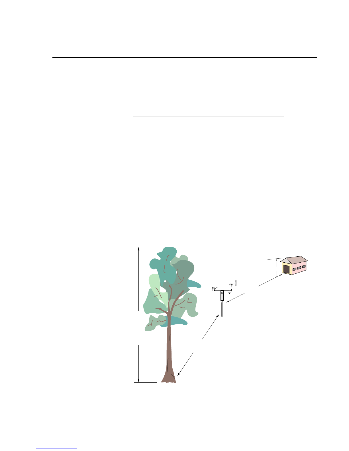
Wind sensors should be located over open level terrain, and at a distance of at
least ten times (EPA) the height of any nearby building, tree or other
obstruction, as illustrated in Figure 1.1-1.
1
, WMO (1983)2, and AASC (1985)3 publications.
10H
Logan, Utah
MADE IN USA
Height of tree (T)
10T
FIGURE 1.1-1. Effect of Structure on Wind Flow
H
1-1

Section 1. Preparation and Siting
1.1.2 Temperature and Relative Humidity
Sensors should be located over an open level area at least 9 m (29.5 ft) (EPA)
in diameter. The surface should be covered by short grass, or where grass does
not grow, the natural earth surface. Sensors should be located at a distance of
at least four times the height of any nearby obstruction and at least 30 m
(98.43 ft) (EPA) from large paved areas. Sensors should be protected from
thermal radiation, and adequately ventilated.
Situations to avoid include:
• large industrial heat sources
• rooftops
• steep slopes
• sheltered hollows
• high vegetation
• shaded areas
• swamps
• areas where snow drifts occur
• low places holding standing water after rains
1.1.3 Solar Radiation
Pyranometers should be located to avoid shadows on the sensor at any time.
Mounting it on the southern most (northern hemisphere) portion of the weather
station will minimize the chance of shading from other weather station
structures. Reflective surfaces and sources of artificial radiation should be
avoided.
1.2 Installation Tasks
1.2.1 Indoors
• Immediately upon receipt of your shipment…
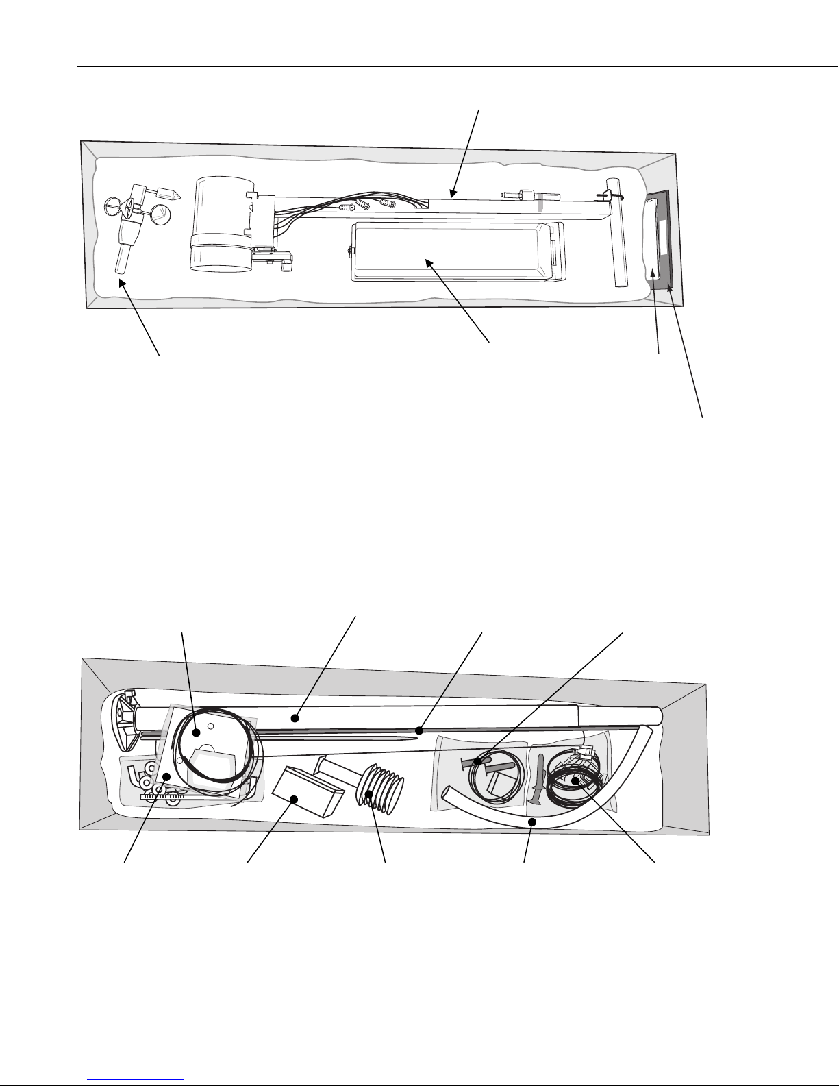
⇒ Weather station is packed in the shipping box in layers. See Figures
1.2-1A, 1.2-1B, 1.2-2, and 1.2-3.
⇒ Immediately upon receipt of your shipment…
Open shipping carton(s).
Set the large weather station carton down lengthwise on a floor or
table top. Position the box as shown in Figure 1.2-1A.
Cut the tape along the edge of the lower flap first. See Figure 1.21A.
Cut the tape around the remaining flaps BUT only cut one layer deep.
Lift up the cardboard flaps exposing the top layer of foam as shown
in Figure 1.2-1B.
1-2
⇒ Check contents against invoice and shipping checklist. Contact
Campbell Scientific immediately about any shortages.

Section 1. Preparation and Siting
THIS SIDE UP
Cut Lower Flap
Edge First
Top Packing
Foam Layer
Middle Packing
Foam Layer
Bottom Packing
Foam Layer
FIGURE 1.2-1A. Cut Flap Packing Tape
FIGURE 1.2-1B. Shipping Box Packaging
T107,
Top Layer
T107,
Bottom Layer
1-3
Section 1. Preparation and Siting
Crossarm with Rain, Solar, and
Temp/%RH Sensors
Manual
Wind Vane
Wind Set
Top Layer
Enclosure
Instruction
Instruction
Manual
Manual
Cardboard
Containing Wind Vane
FIGURE 1.2-2. T107 with the Met One 034B-ETM Wind Sensor, Top
Layer
Mounting Template Grounding Wire
and Enclosure Desiccant Packs
DESI PAK
Mounting Bolts
and Hardware
Enclosure
Battery
2-Piece Pole Grounding and
Lightning Rod
BATTERY
Temp/%RH
Bottom Layer
Gill Radiation
Shield
301-T
PVC Swept
Elbow Conduit
AC Transformer
and Cabling
Communication
Option Cabling
FIGURE 1.2-3. T107, Bottom Layer
1-4

1.2.2 Outdoors
Section 1. Preparation and Siting
⇒ Securely tape box shut if transporting entire station to another site. If
at the main site, remove any communication components that are
installed at the calling computer. Repackage remaining components
for transport to field site.
Solar panel and RF items (if any) will be packed in a separate box.
• Several days prior to the planned installation date…
⇒ Collect tools and site information (Section 1)
⇒ Install datalogger support software (Section 3)
• Locate suitable site (Section 1)
• Prepare concrete base (Section 2)
• T107 Installation:
⇒ Place instrumentation enclosure on the ET pole. Slide enclosure to the
1.3 Tools Required
Tools required to install and maintain a weather station are listed below.
1.3.1 Tools for Pole Installation
ET Pole
Shovel
Rake
Open end wrenches: 3/8", 7/16", 1/2", (2) 9/16"
Magnetic compass
6' Step ladder
Tape measure (12’ to 20’)
Claw hammer
Level (24” to 36”)
Hand saw
Materials for concrete form:
(4) 1" x 2" x 12" stakes
(2) 2" x 4" x 96" lumber
(12) 8p double-head nails
(8) 16p double-head nails
20 ft form wire
½ Yard concrete
Concrete trowel, edger
Electrical Fish tape or 20 feet of small diameter rope
Wheelbarrow
top of the pole and secure with correct orientation (Section 2.3).
1-5

Section 1. Preparation and Siting
1.3.2 Tools for Instrumentation and Maintenance
ET Pole
Lock and key for enclosure
Magnetic declination angle
Magnetic compass
Straight bit screwdrivers (small, medium, large)
Phillips-head screwdrivers (small, medium)
Small diagonal side-cutters
Needle-nose pliers
Wire strippers
Pocket knife
Calculator
Volt / Ohm Meter
Electrical Tape
Step ladder (6')
Station manuals
Station log and pen
Open end wrenches: 3/8", 7/16", 1/2", 9/16", 15/16"
Socket wrench and 7/16" deep well socket
Adjustable wrench
Pliers
Conduit and associated tools (as required)
Felt-tipped marking pen
Claw hammer
Pipe wrench (12")
1.4 Supplies for Power and Communications Options
AC Power
Wire, conduit, and junction boxes as needed (see Figure 2.1-1).
NOTE
User supplies valve box at base of station and weatherproof
enclosure for transformer. See Figure 2.1-1.
Phone Modem
Phone modem at the central computer.
Dedicated single twisted pair with shield phone line to the weather station
valve/junction box (see Figure 2.1-1).
Short-Haul Modem
Direct burial cable with a minimum of 2-twisted pairs with shield (minimum 5
conductors total) to travel from the weather station to the central computer
junction box. Direct burial armored cable may be required for rocky soils or
rodents (Anixter p/n F-02P22BPN (phone 847.677.2600)) or equivalent type
cable (see Figure 2.1-1).
RF450
Antenna for the T107 station (14205 Yagi antenna recommended). PS24
Power Supply and #18520 Hanger Kit if not using ac power (see Appendix B).
1-6
Section 1. Preparation and Siting
1.5 Determining True North for Wind Vane
Orientation
Magnetic declination, or other methods to find True North, should be determined
prior to installing the weather station. True North is usually found by reading a
magnetic compass and applying the correction for magnetic declination*; where
magnetic declination is the number of degrees between True North and Magnetic
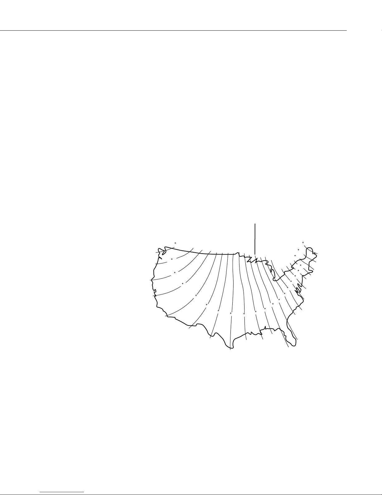
North. Magnetic declination for a specific site can be obtained from a USFA map,
local airport, or through a NOAA website (Section 1.5.1). A general map showing
magnetic declination for the contiguous United States is shown in Figure 1.5-1.
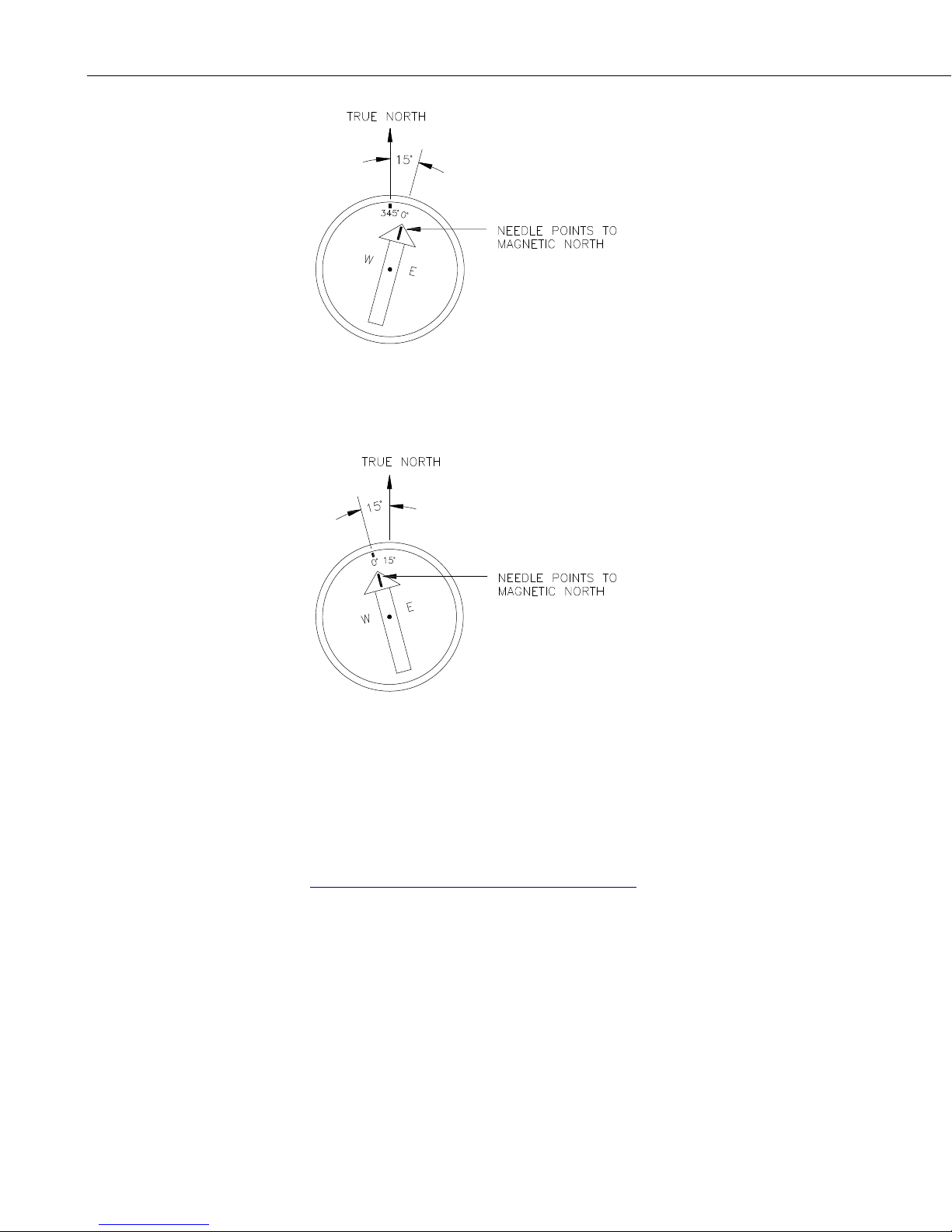
Declination angles east of True North are considered negative, and are subtracted
from 0 degrees to get True North as shown Figure 1.5-2. Declination angles west
of True North are considered positive, and are added to 0 degrees to get True
North as shown in Figure 1.5-3. For example, the declination for Logan, Utah is
12.4° East. True North is 360° - 12.4° = 347.6° as read on a compass.
* Other methods employ observations using the North Star or the sun, and
are discussed in the Quality Assurance Handbook for Air Pollution
Measurement Systems, Volume IV - Meteorological Measurements
4
.
Subtract declination from 360° Add declination to 0°
20 W
18 W
16 W
14 W
12 W
10 W
8 W
6 W
4 W
20 E
22 E
18 E
16 E
14 E
12 E
10 E
8 E
6 E
4 E
2 E
2 W
0
FIGURE 1.5-1. Magnetic Declination for the Contiguous United States
1-7
Section 1. Preparation and Siting
FIGURE 1.5-2. Declination Angles East of True North Are
Subtracted From 0 to Get True North
FIGURE 1.5-3. Declination Angles West of True North Are
Added to 0 to Get True North
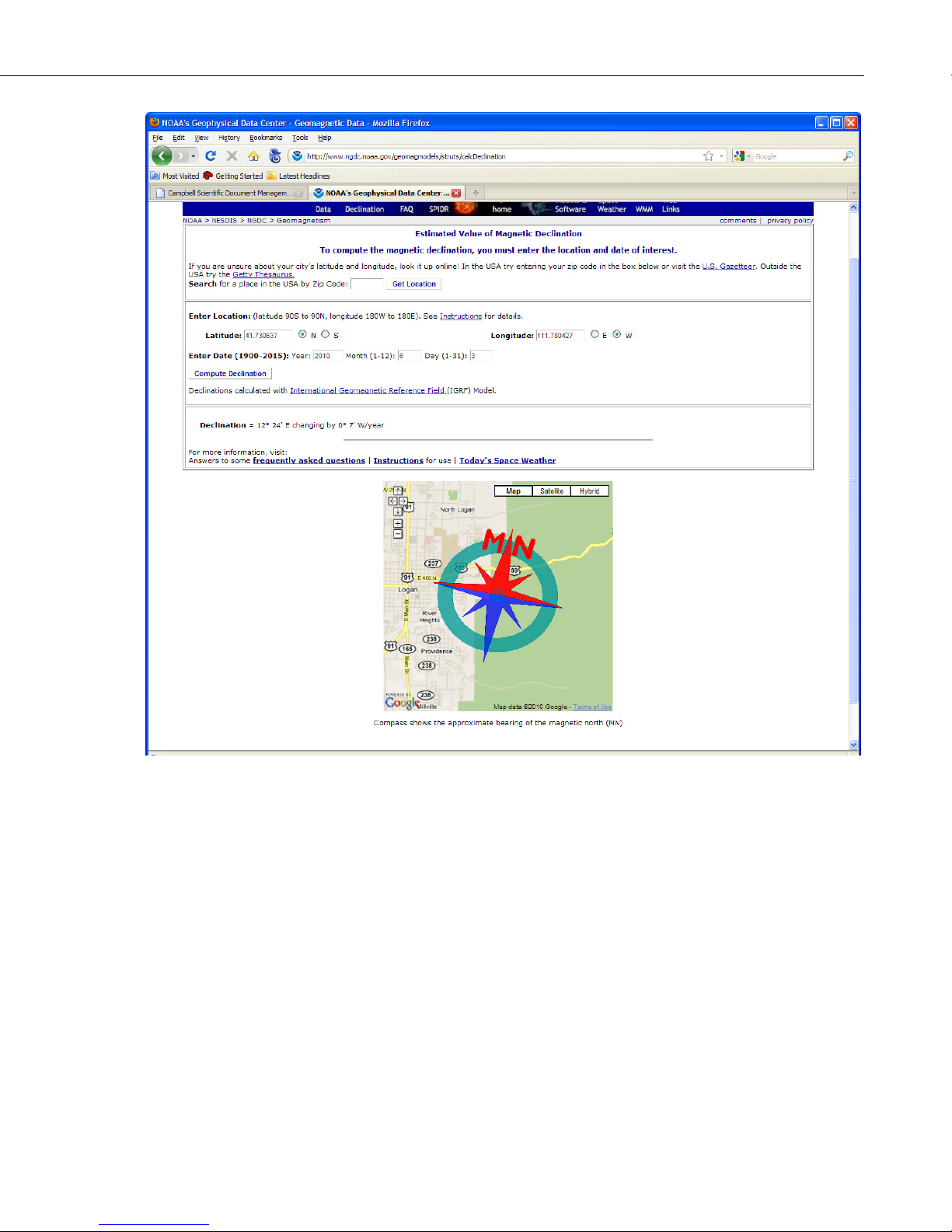
1.5.1 Web Calculator
Since magnetic declination fluctuates with time, it should be determined each
time the wind sensor orientation is adjusted. It can be accessed at
www.ngdc.noaa.gov/geomagmodels/Declination.jsp
Below is an example for Logan, UT.
1-8
Section 1. Preparation and Siting
References
A positive declination is east, while a negative declination is west. The
declination in this example is 12º 24′ or 12.4º. As shown in Figure 1.5-1, the
declination for Logan, UT is east, so True North for this site is 360 – 12.4, or
347.6 degrees.
1
EPA, (1987). On-Site Meteorological Program Guidance for Regulatory
Modeling Applications, EPA-450/4-87-013. Office of Air Quality Planning
and Standards, Research Triangle Park, North Carolina 27711.
2
WMO, (1983). Guide to Meteorological Instruments and Methods of
Observation. World Meteorological Organization No. 8, 5th edition, Geneva,
Switzerland.
3
The State Climatologist, (1985) Publication of the American Association of
State Climatologists: Height and Exposure Standards for Sensors on
Automated Weather Stations, v. 9, No. 4 October, 1985.
1-9

Section 1. Preparation and Siting
4
Systems, EPA Office of Research and Development, Research Triangle Park,
North Carolina 27711.
EPA, (1989). Quality Assurance Handbook for Air Pollution Measurement
1-10

Section 2. Hardware Installation
DANGER: Do not install near power lines. If any part of the tower comes in contact with
power lines you could be KILLED. Contact local utilities for the location of buried utility
lines before digging or driving grounding rods.
CAUTION: Do not fit the 3 meter ET Tower sections together until the appropriate time.
Once attached, they cannot be detached.
The ET Tower provides a support structure for mounting the T107 weather station
components. Figure 2.1-1 shows a typical ET Tower installation option. The tower is
designed to withstand winds of 100 mph. The lightning rod assembly is attached after the
instrumentation enclosure is installed.
100-240 VAC
50 or 60 Hz
Power Supply
Communications
Line
FIGURE 2.1-1. ET tower installation with currently-available AC power
User Supplied
Junction Box
24 VDC
Power
option
Valve Box
Direct Bury
Splices
ET Tower
Ground
Rod
Concrete
Base
NOTE
NOTE
User supplies valve box at base of station and weatherproof
enclosure for transformer. See Figure 2.1-1.
The AC power supply option at one time included a step-down
transformer instead of the power supply. Appendix E provides
information about using the step-down transformer.
2-1

Section 2. Hardware Installation
2.1 Base Foundation
2.1.1 Supplied Components
(3) 5/8 inch Anchor L-Bolts
(9) 5/8 inch Nuts
(1) Anchor Template
Refer to Section 1 for components supplied by installer and bring components.
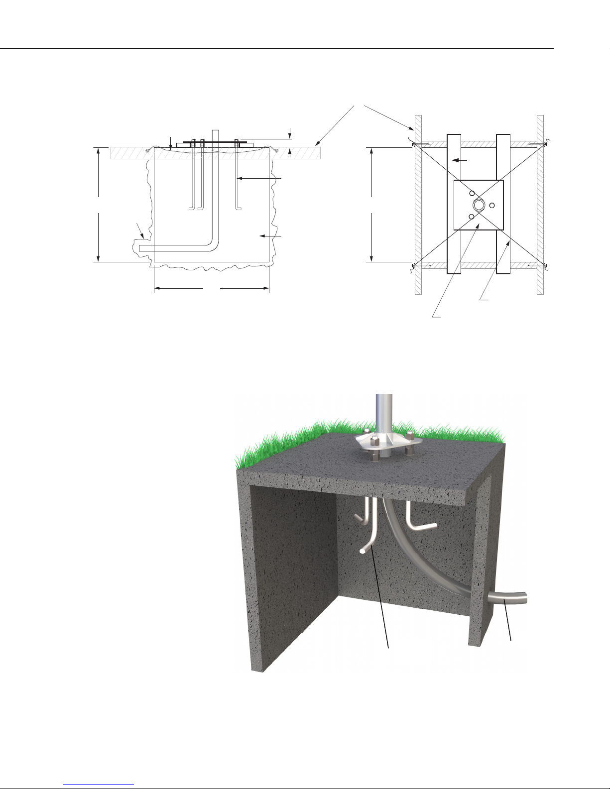
2.1.2 Installation
1. The ET Tower attaches to a user supplied concrete foundation constructed
as shown in Figure 2.1-2.
2. Construct the concrete form with 2" x 4" lumber and 16p nails.
3. Assemble the template and anchor bolts. There should be two nuts below
and one nut above the template on each bolt.
4. Clear an area large enough to set the form at the desired elevation.
5. Dig a hole 2 feet x 2 feet x 2 feet. Lighter soils may require a deeper hole.
About 20 inches below the top of the hole, gouge a small cavity in one
wall of the hole. The cavity should be about 4 inches deep and just large
enough in diameter to insert one end of the conduit. Make certain the
cavity "points" in the direction from which power and communications
cables will come. For example the cavity will “point” towards a valve box
if one is being used.
6. Center the form over the hole. Adjacent to the form, drive four stakes into
the soil. Secure the leveled form to the stakes with the 8p nails.
7. Cap the ends of the conduit with duct tape. Position the conduit and wire
into place by securing the wire to nails in the form.
8. Fill the hole and form with approximately ½ yard of concrete. Screed the
concrete level with the top of the form. Center the template assembly over
the conduit and press into the concrete. Put 2 x 4 spacers between the
template and the top of the form. The bottom of the bolt threads should be
about ½ inch above the concrete. The template must be level in two
dimensions. Use a trowel and edger to finish.
9. Wait 24 hours before removing the concrete form. Wait 7 days before
mounting the ET Tower.
2-2
Section 2. Hardware Installation
24"
SMALL
CAVITY
FORM WIRE
SIDE VIEW
24"
FORM
2"
ANCHOR BOLT
24"
CEMENT PAD
FIGURE 2.1-2. ET Tower Base Installation
TOP VIEW
NORTH
FORM WIRE
TEMPLATE
Anchor
Bolt
FIGURE 2.1-3. Cut-Away View Shows Anchor Bolt and Conduit
Placement in Cement Pad
Conduit
2-3

Section 2. Hardware Installation
2.1.3 AC Power Installation
a) The currently-available AC power option includes a 100 to 240 VAC to
24 VDC power supply (see note below). The power supply should be
mounted inside a user-supplied junction box according to local electrical
codes. Dangerous electrical accidents may be avoided by locating the
transformer remotely and burying a low voltage line to the station. The
low voltage will carry up to 500 feet on an 18 AWG power cable.
b) Shut off 110 VAC power at the main breaker. Connect the primary leads
of the power supply to the 100 to 240 VAC power source. Connect a twoconductor cable to the secondary terminals of the power supply. Route the
cable from the power supply to the ET Enclosure according to local
electrical codes.
c) Splice the incoming two-conductor cable to the power cable provided with
the station. Use the direct burial splice kit when splices are in a valve box
or buried.
d) Connect the power plug to the connector marked “Power” on the back of
the enclosure. See Figure 2.4-17.
NOTE
CAUTION
2.2 Tower/Pole
2.2.1 Supplied Components
2.2.2 Installation
The AC power supply option for older T107 stations included a
120 VAC to 16 VAC step-down transformer instead of the 100
to 240 VAC to 24 VDC power supply. Appendix E provides
information for installing an AC power system that includes the
step-down transformer.
The splice and wire nut must be completely immersed into
the silicon gel inside the splice tube to be waterproof.
(1) Upper Tower Section (Tapered)
(1) Lower Tower Section
(6) 5/8 inch Washers
(1) 12 foot 10 AWG Ground Cable
(1) White Tower Cap
(1) 20' communications cable (phone or short haul modem)
(1) 20' power cable (for AC option only)
Attach the tower to the base as shown in Figure 2.2-1.
1. Dig a hole close to the concrete base to access the lower conduit opening.
2. Remove the template. Slide the bottom and top half of the pole pieces
2-4
From the hole, trench to the power and communications sources. Remove
the duct tape from both ends of the conduit.
together. This is a permanent connection and cannot be taken apart once

Section 2. Hardware Installation
they are put together. If a little more force is necessary to put the two
halves together, then get a small block of scrap wood and a hammer. Set
the pole upright on a grassy area or have someone hold the pole
horizontally. Place a piece of scrap wood over the very end of the top
section of the pole and gently hammer on the scrap wood to fit the two
halves together. A 1.27 cm (1/2 inch) gap between the top and bottom
pole sections is acceptable. Lay the assembled pole on the ground next to
the concrete foundation.
3. Cut and save a 9 inch piece of 12 AWG ground wire from the 12 foot
length provided. This will be used later to attach the enclosure ground to
the lightning rod assembly (reference Figure 2.3-1).
4. Thread communication cable, power cable with connector ends of cable
out the top of tower, and grounding wire through the tower and conduit.
Electrical fish tape will help. Leave approximately two feet of the
supplied power and communication cable hanging out of the top of the
pole. Secure all wiring so it doesn’t slip back down through the pole.
NOTE
Solar panel and RF options will not have power or
communication cables.
5. Place the white tower cap over the tower end.
6. Raise the tower on a still day. Place a washer on top of the two nuts on
each foundation bolt. Taking great care not to damage cables between the
tower and conduit, raise the tower and lower it onto the conduit and
mounting bolts. Install a washer and nut on each bolt and hand tighten.
Check plumb of the tower by placing a level on the north and east sides of
the lower tower section. Adjust the topmost of the two lower nuts
(leveling nut) on each bolt as necessary. When plumb is established, lock
the leveling nut in place by tightening the lowest nut against it. Tighten
the three top nuts with the wrench.
2-5
Section 2. Hardware Installation
Nut
4 AWG Wire
Ground Rod
ET Tower
Leveling
Concrete
Foundation
Anchor Bolt
Swept Elbow Conduit
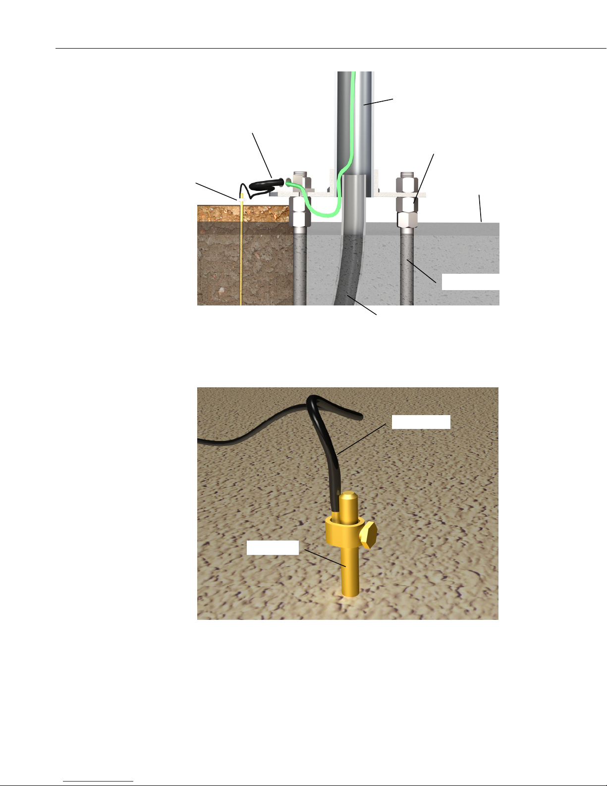
FIGURE 2.2-1. Transparent View Shows Raising and Grounding the
ET Tower
4 AWG Wire
Ground Rod
FIGURE 2.2-2. Close up of Ground Rod and 4 AWG Cable
2-6

2.2.3 Tower Grounding
2.2.3.1 Supplied Components
(1) 5 foot 4 AWG Ground Cable
(1) Copper Ground Lug, Bolt
(1) Ground Rod, Clamp
2.2.3.2 Grounding Procedure
Ground the tower as shown in Figures 2.2-1 and 2.2-2.
1. Place the ground rod clamp on the ground rod. Secure it about 3 inches
from the top. Do this before the rod is driven into the ground. Be careful
not to damage the clamp with the hammer
2. Taking care not to damage power or communications lines, drive the
ground rod close to the foundation using a fence post driver or sledge
hammer. Drive the rod at an angle if an impenetrable hardpan layer exists.
Soften hard clay soils with water if necessary.
3. Strip 1 inch of insulation from both ends of the 4 AWG ground cable.
Strip 1 inch of insulation from the lower end of the 12 AWG ground wire.
Loosen the lug's set screw and insert the 4 AWG and 12 AWG wire.
Tighten the set screw (Figure 2.2-2).
Section 2. Hardware Installation
4. Loosen the ground rod clamp. Insert the 4 AWG wire. Tighten the clamp
(Figure 2.2-2).
2-7
Section 2. Hardware Installation
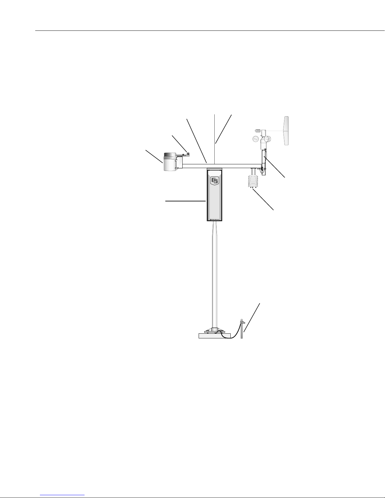
2.3 Enclosure
The weather station datalogger, power supply, sensor connection panel,
communications devices, and data retrieval peripherals are mounted in the ET
enclosure. Refer to Appendix C.1 for a labeled, exploded view of the
enclosure.
Pyranometer
Tipping Bucket
Rain Gage
ET Enclosure
Crossarm
Lightning
Rod
Met One 034B
Wind Set
Radiation
Logan, Utah
MADE IN USA
Shield
2-8
FIGURE 2.3-1. T107 Instrumentation Mounted on the ET Tower
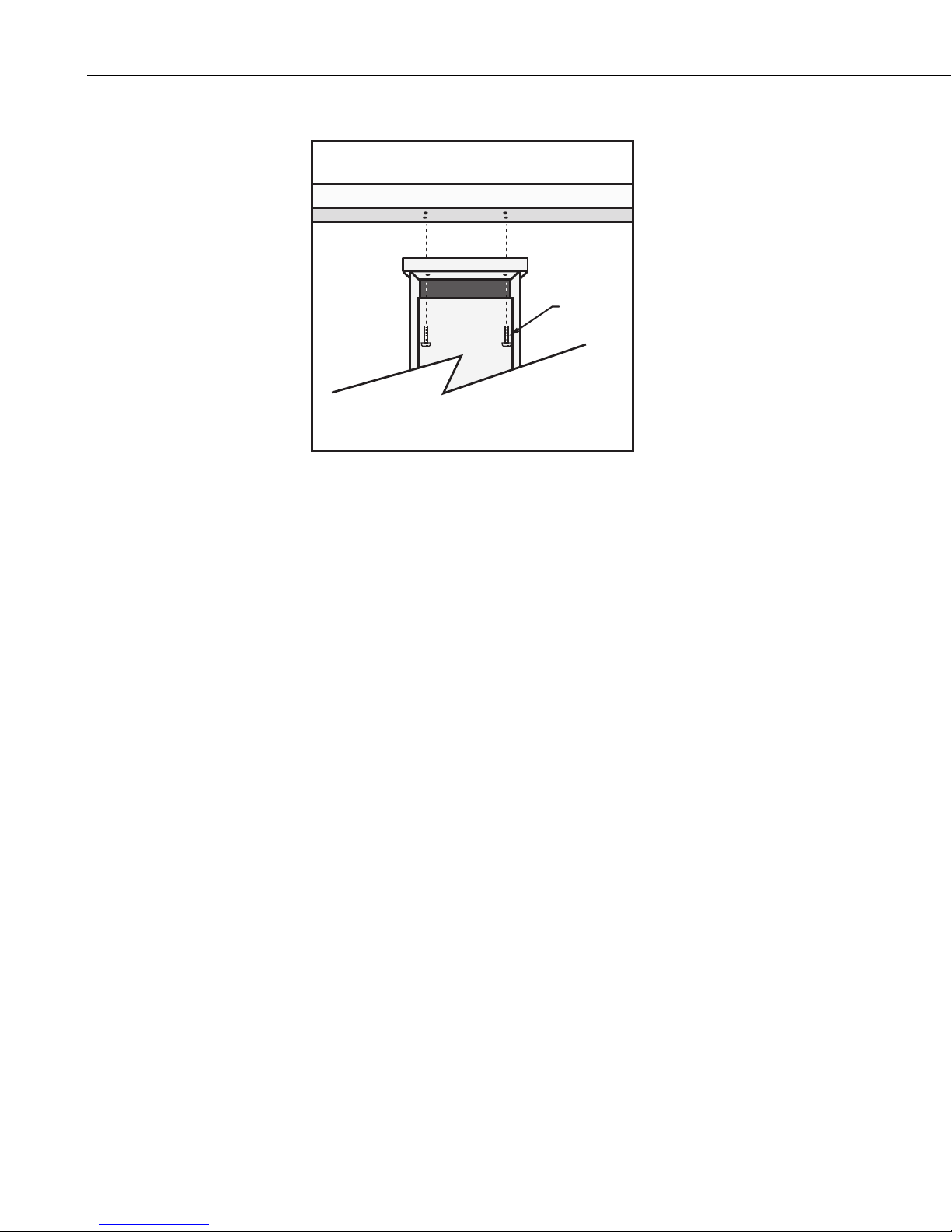
2.3.1 Enclosure Installation
1. Mount the ET enclosure on the ET Tower as shown in Figure 2.3-2.
a. Remove the front lid. Remove the connector cover from the back of
the ET enclosure by loosening the Phillips screw at the bottom of the
cover.
Ground
Rod
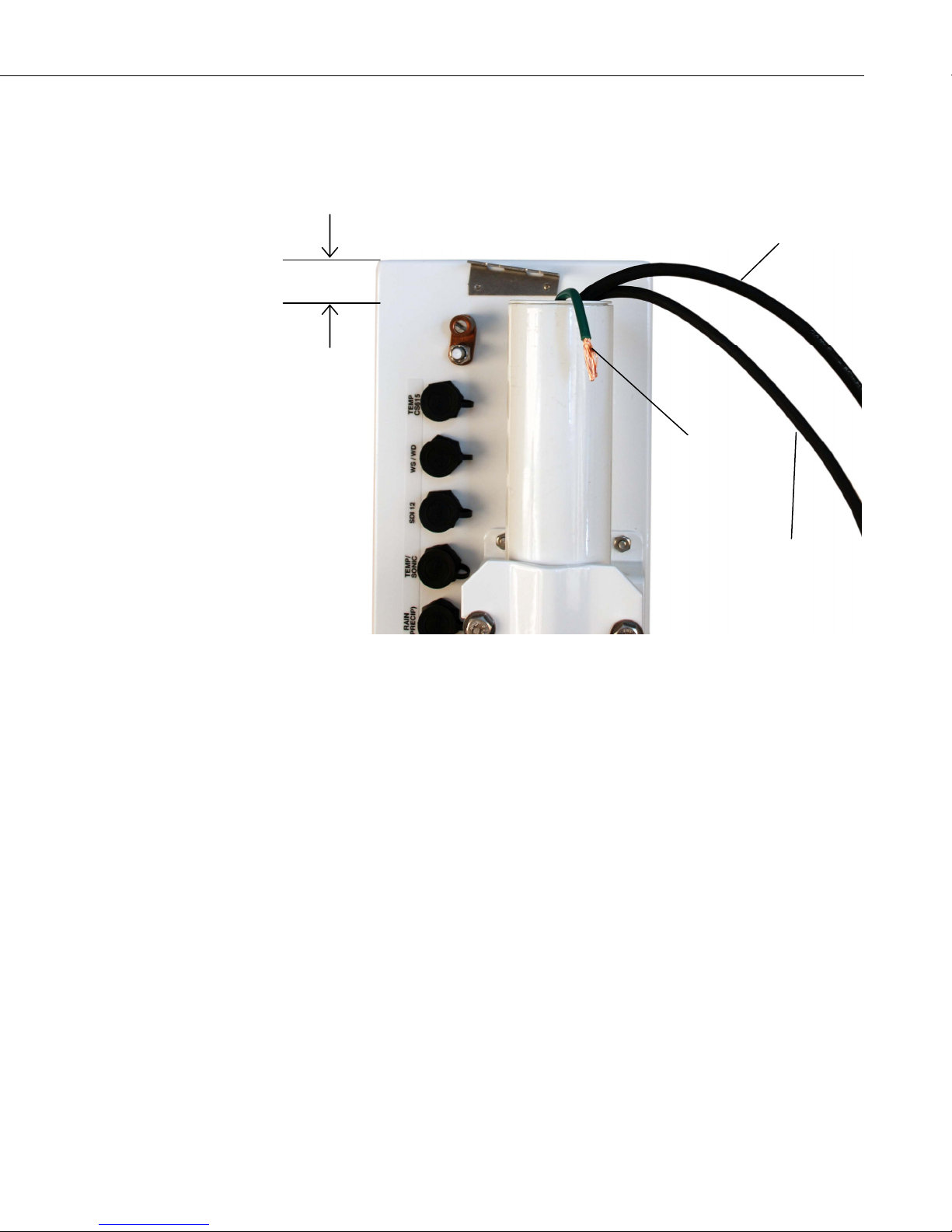
2 – 2.5 cm
Section 2. Hardware Installation
b. Loosen the mounting bracket bolts on the back of the enclosure wide
enough to slide over the pole. Slide the enclosure over the pole.
Position the enclosure so it faces east for northern latitudes or west
for southern latitudes. The top of the enclosure should be 2 – 2.5 cm
(3/4” to 1”) above the top of the pole (see Figure 2.3-2).
Power Cable
(if using AC
transformer)
Ground
Wire
FIGURE 2.3-2. Enclosure Spacing Above Pole
2.4 Crossarm and Sensor Installation
Refer to Appendix C.2 for a labeled, exploded view of the crossarm.
2.4.1 Components
(1) T107 Crossarm with Sensors (see Figure 2.3-1)
(1) Met One 034B or Gill WindSonic Wind Sensor
(1) White Mounting Shaft for 034B or Gill WindSonic
(1) Gill Radiation Shield
2.4.2 Crossarm Installation
Adjust the bolts at the base of the pole to vertically level the top section of the
mounting pole. Install the T107 Sensor Arm after the ET Enclosure is
mounted on the ET Tower. You may need to temporarily remove the
communications option. Mount the sensor arm as shown in Figure 2.4-1
without the wind sensor attached.
COM Cable
(if using phone or
short-haul modem)
2-9
Section 2. Hardware Installation
Screws
(4)
FIGURE 2.4-1. T107 Sensor Arm Mounting
1) Remove the front lid and the protective connector cover from the back of
the ET enclosure by loosening the one Phillips screw at the bottom of the
cover.
2) Place the sensor arm on top of the enclosure, lining up the four threaded
holes on the under side of the arm with the four holes in the top of the
enclosure. Attach the arm to the enclosure by inserting and tightening
four Phillips head screws. Adjust the position of the ET Enclosure so that
the crossarm is oriented along a due north to due south axis with the rain
gage and solar radiation sensor (pyranometer) on the south side for
northern latitudes and the reverse for southern latitudes.
2-10
 Loading...